Optical Imaging Lens Assembly
GAO; Xue ; et al.
U.S. patent application number 16/940567 was filed with the patent office on 2020-11-12 for optical imaging lens assembly. This patent application is currently assigned to Zhejiang Sunny Optical Co., Ltd.. The applicant listed for this patent is Zhejiang Sunny Optical Co., Ltd. Invention is credited to Xue GAO, Ming LI, Jianke WENREN.
| Application Number | 20200355893 16/940567 |
| Document ID | / |
| Family ID | 1000005005586 |
| Filed Date | 2020-11-12 |


View All Diagrams
| United States Patent Application | 20200355893 |
| Kind Code | A1 |
| GAO; Xue ; et al. | November 12, 2020 |
OPTICAL IMAGING LENS ASSEMBLY
Abstract
The present disclosure discloses an optical imaging lens assembly which includes sequentially from an object side to an image side along an optical axis, a first lens, a second lens, a third lens, a fourth lens, a fifth lens and a sixth lens. The first lens has a positive refractive power with a convex object-side surface; the second lens has a refractive power with a concave image-side surface; the third lens has a refractive power with a convex object-side surface; the fourth lens has a refractive power with a concave object-side surface; the fifth lens has a refractive power; and the sixth lens has a refractive power with a concave object-side surface. A maximum effective radius DT11 of the object-side surface of the first lens and a maximum effective radius DT61 of the object-side surface of the sixth lens satisfy 0.6<DT11/DT61<1.
| Inventors: | GAO; Xue; (Zhejiang Province, CN) ; LI; Ming; (Zhejiang Province, CN) ; WENREN; Jianke; (Zhejiang Province, CN) | ||||||||||
| Applicant: |
|
||||||||||
|---|---|---|---|---|---|---|---|---|---|---|---|
| Assignee: | Zhejiang Sunny Optical Co.,
Ltd. Zhejiang Province CN |
||||||||||
| Family ID: | 1000005005586 | ||||||||||
| Appl. No.: | 16/940567 | ||||||||||
| Filed: | July 28, 2020 |
Related U.S. Patent Documents
| Application Number | Filing Date | Patent Number | ||
|---|---|---|---|---|
| PCT/CN2019/077466 | Mar 8, 2019 | |||
| 16940567 | ||||
| Current U.S. Class: | 1/1 |
| Current CPC Class: | G02B 13/0045 20130101; G02B 27/0025 20130101; G02B 9/62 20130101 |
| International Class: | G02B 13/00 20060101 G02B013/00; G02B 9/62 20060101 G02B009/62; G02B 27/00 20060101 G02B027/00 |
Foreign Application Data
| Date | Code | Application Number |
|---|---|---|
| May 2, 2018 | CN | 201810411178.3 |
Claims
1. An optical imaging lens assembly, sequentially from an object side to an image side along an optical axis, comprising a first lens, a second lens, a third lens, a fourth lens, a fifth lens and a sixth lens, wherein, the first lens has a positive refractive power with a convex object-side surface; the second lens has a refractive power with a concave image-side surface; the third lens has a refractive power with a convex object-side surface; the fourth lens has a refractive power with a concave object-side surface; the fifth lens has a refractive power; and the sixth lens has a refractive power with a concave object-side surface; a maximum effective radius DT11 of the object-side surface of the first lens and a maximum effective radius DT61 of the object-side surface of the sixth lens satisfy 0.6<DT11/DT61<1.
2. The optical imaging lens assembly according to claim 1, wherein a total effective focal length f of the optical imaging lens assembly and half of a maximal field-of-view angle HFOV of the optical imaging lens assembly satisfy 1.6<f*TAN(HFOV)<2.4.
3. The optical imaging lens assembly according to claim 1, wherein a total effective focal length f of the optical imaging lens assembly, an effective focal length f1 of the first lens and half of a maximal field-of-view angle HFOV of the optical imaging lens assembly satisfy 4.5.ltoreq.f/f1/TAN(HFOV)<6.5.
4. The optical imaging lens assembly according to claim 1, wherein a total effective focal length f of the optical imaging lens assembly and a distance TTL along the optical axis from the object-side surface of the first lens to an imaging plane of the optical imaging lens assembly satisfy TTL/f<1.05.
5. The optical imaging lens assembly according to claim 4, wherein an effective focal length f1 of the first lens and the total focal length f of the optical imaging lens assembly satisfy 0.5<f1/f<1.
6. The optical imaging lens assembly according to claim 4, wherein the total focal length f of the optical imaging lens assembly, a radius of curvature R7 of the object-side surface of the fourth lens and a radius of curvature R8 of an image-side surface of the fourth lens satisfy |f/R7-f/R8|<2.5.
7. The optical imaging lens assembly according to claim 1, wherein an effective focal length f1 of the first lens and a sum .SIGMA.CT of center thicknesses along the optical axis of the first lens to the sixth lens satisfy 1<f1/.SIGMA.CT<2.
8. The optical imaging lens assembly according to claim 7, wherein a center thickness CT2 along the optical axis of the second lens, a center thickness CT3 along the optical axis of the third lens and a center thickness CT4 along the optical axis of the fourth lens satisfy (CT2+CT4)/CT3<1.
9. The optical imaging lens assembly according to claim 7, wherein 0.5<CT1/(T45+CT5+T56+CT6)<1.5, where CT1 is a center thickness along the optical axis of the first lens, T45 is a spaced interval along the optical axis between the fourth lens and the fifth lens, CT5 is a center thickness along the optical axis of the fifth lens, T56 is a spaced interval along the optical axis between the fifth lens and the sixth lens, and CT6 is a center distance along the optical axis of the sixth lens.
10. The optical imaging lens assembly according to claim 7, wherein a spaced interval T23 along the optical axis between the second lens and the third lens, a spaced interval T34 along the optical axis between the third lens and the fourth lens, a spaced interval T45 along the optical axis between the fourth lens and the fifth lens satisfy (T23+T45)/T34<0.4.
11. The optical imaging lens assembly according to claim 1, wherein a distance SAG41 along the optical axis from an intersection of the object-side surface of the fourth lens and the optical axis to a vertex of an effective radius of the object-side surface of the fourth lens and a spaced distance T34 along the optical axis between the third lens and the fourth lens satisfy |SAG41/T34|<0.5.
12. The optical imaging lens assembly according to claim 1, wherein a radius of curvature R1 of the object-side surface of the first lens, a radius of curvature R4 of the image-side surface of the second lens, a radius of curvature R5 of the object-side surface of the third lens and a radius of curvature R11 of the object-side surface of the sixth lens satisfy -1.5<(R5+R11)/(R1+R4)<0.5.
13. The optical imaging lens assembly according to claim 1, wherein an effective focal length f2 of the second lens, an effective focal length f3 of the third lens and an effective focal length f6 of the sixth lens satisfy -1<(1/f3+1/f6)*f2<1.5.
14. An optical imaging lens assembly, sequentially from an object side to an image side along an optical axis, comprising, a first lens, a second lens, a third lens, a fourth lens, a fifth lens and a sixth lens, wherein: the first lens has a positive refractive power with a convex object-side surface; the second lens has a refractive power with a concave image-side surface; the third lens has a refractive power with a convex object-side surface; the fourth lens has a refractive power with a concave object-side surface; the fifth lens has a refractive power; and the sixth lens has a refractive power with a concave object-side surface; a combined focal length f123 of the first lens, the second lens and the third lens and a combined focal length f456 of the fourth lens, the fifth lens and the sixth lens satisfy |f123/f456|<1.
15. The optical imaging lens assembly according to claim 14, wherein an effective focal length f1 of the first lens and a total effective focal length f of the optical imaging lens assembly satisfy 0.5<f1/f<1.
16. The optical imaging lens assembly according to claim 14, wherein a total focal length f of the optical imaging lens assembly, a radius of curvature R7 of the object-side surface of the fourth lens and a radius of curvature R8 of an image-side surface of the fourth lens satisfy |f/R7-f/R8|<2.5.
17. The optical imaging lens assembly according to claim 14, wherein an effective focal length f2 of the second lens, an effective focal length f3 of the third lens and an effective focal length f6 of the sixth lens satisfy -1<(1/f3+1/f6)*f2<1.5.
18. The optical imaging lens assembly according to claim 14, wherein an effective focal length f1 of the first lens and a sum .SIGMA.CT of center thicknesses along the optical axis of the first lens to the sixth lens satisfy 1<f1/.SIGMA.CT<2.
19. The optical imaging lens assembly according to claim 14, wherein a total effective focal length f of the optical imaging lens assembly and half of a maximal field-of-view angle HFOV of the optical imaging lens assembly satisfy 1.6<f*TAN(HFOV)<2.4.
20. The optical imaging lens assembly according to claim 14, wherein a total effective focal length f of the optical imaging lens assembly and a distance TTL along the optical axis from the object-side surface of the first lens to an imaging plane of the optical imaging lens assembly satisfy TTL/f<1.05.
Description
CROSS-REFERENCE TO RELATED APPLICATION
[0001] The present patent application is a continuation of International Application No. PCT/CN2019/077466, filed on Mar. 8, 2019, which claims the priority from Chinese Patent Application No. 201810411178.3, filed before the China National Intellectual Property Administration (CNIPA) on May 2, 2018. Both of the aforementioned patent applications are hereby incorporated by reference in their entireties.
TECHNICAL FIELD
[0002] The present disclosure relates to an optical imaging lens assembly, and specifically to an optical imaging lens assembly including six lenses.
BACKGROUND
[0003] With the rapid replacement of consumer electronic products, such as smart phones, portable computers and tablet devices, the market is increasingly demanding the quality of optical imaging lens assemblies for electronic products. The optical imaging lens assemblies are not only required to have basic performance, such as high resolution and high relative brightness, but also required to have long-focus characteristics. However, for the existing long-focus lens assembly, high imaging quality is usually achieved by increasing the number of lenses, but the size of the long-focus lens assembly will be larger, which cannot meet the requirements of ultra-thin and miniaturization of current electronic devices while satisfying the long-focus characteristics and high imaging quality.
SUMMARY
[0004] The present disclosure provides an optical imaging lens assembly which is applicable to portable electronic products and may at least solve or partially solve at least one of the technical problems mentioned above in the prior art.
[0005] The present disclosure provides an optical imaging lens assembly including, sequentially from an object side to an image side along an optical axis, a first lens, a second lens, a third lens, a fourth lens, a fifth lens and a sixth lens. The first lens may have a positive refractive power, of which an object-side surface may be a convex surface; the second lens has a positive or negative refractive power, of which an image-side surface may be a concave surface; the third lens has a positive or negative refractive power, of which an object-side surface may be a convex surface; the fourth lens has a positive or negative refractive power, of which an object-side surface may be a concave surface; the fifth lens has a positive or negative refractive power; and the sixth lens has a positive or negative refractive power, of which an object-side surface may be a concave surface.
[0006] In one implementation, a maximum effective radius DT11 of the object-side surface of the first lens and a maximum effective radius DT61 of the object-side surface of the sixth lens may satisfy 0.6<DT11/DT61<1.
[0007] In one implementation, a total effective focal length f of the optical imaging lens assembly and half of a maximal field-of-view angle HFOV of the optical imaging lens assembly may satisfy 1.6<f*TAN(HFOV)<2.4.
[0008] In one implementation, a total effective focal length f of the optical imaging lens assembly, an effective focal length f1 of the first lens and half of a maximal field-of-view angle HFOV of the optical imaging lens assembly may satisfy 4.5.ltoreq.f/f1/TAN(HFOV)<6.5.
[0009] In one implementation, a total effective focal length f of the optical imaging lens assembly and a distance TTL along the optical axis from the object-side surface of the first lens to an imaging plane of the optical imaging lens assembly may satisfy TTL/f<1.05.
[0010] In one implementation, an effective focal length f1 of the first lens and the total focal length f of the optical imaging lens assembly may satisfy 0.5<f1/f<1.
[0011] In one implementation, the total focal length f of the optical imaging lens assembly, a radius of curvature R7 of the object-side surface of the fourth lens and a radius of curvature R8 of an image-side surface of the fourth lens may satisfy |f/R7-f/R8|<2.5.
[0012] In one implementation, an effective focal length f1 of the first lens and a sum .SIGMA.CT of center thicknesses along the optical axis of the first lens to the sixth lens may satisfy 1<f1/.SIGMA.CT<2.
[0013] In one implementation, a center thickness CT2 along the optical axis of the second lens, a center thickness CT3 along the optical axis of the third lens and a center thickness CT4 along the optical axis of the fourth lens may satisfy (CT2+CT4)/CT3<1.
[0014] In one implementation, a center thickness CT1 along the optical axis of the first lens, a spaced interval T45 along the optical axis between the fourth lens and the fifth lens, a center thickness CT5 along the optical axis of the fifth lens, a spaced interval T56 along the optical axis between the fifth lens and the sixth lens, and a center distance CT6 along the optical axis of the sixth lens may satisfy 0.5<CT1/(T45+CT5+T56+CT6)<1.5.
[0015] In one implementation, a spaced interval T23 along the optical axis between the second lens and the third lens, a spaced interval T34 along the optical axis between the third lens and the fourth lens, a spaced interval T45 along the optical axis between the fourth lens and the fifth lens may satisfy (T23+T45)/T34<0.4.
[0016] In one implementation, a combined focal length f123 of the first lens, the second lens and the third lens, and a combined focal length f456 of the fourth lens, the fifth lens and the sixth lens may satisfy |f123/f456|<1.
[0017] In one implementation, a distance SAG41 along the optical axis from an intersection of the object-side surface of the fourth lens and the optical axis to a vertex of an effective radius of the object-side surface of the fourth lens and a spaced interval T34 along the optical axis between the third lens and the fourth lens may satisfy |SAG41/T34|<0.5.
[0018] In one implementation, a radius of curvature R1 of the object-side surface of the first lens, a radius of curvature R4 of the image-side surface of the second lens, a radius of curvature R5 of the object-side surface of the third lens and a radius of curvature R11 of the object-side surface of the sixth lens may satisfy -1.5<(R5+R11)/(R1+R4)<0.5.
[0019] In one implementation, an effective focal length f2 of the second lens, an effective focal length f3 of the third lens and an effective focal length f6 of the sixth lens may satisfy -1<(1/f3+1/f6)*f2<1.5.
[0020] The present disclosure employs six lenses, and the optical imaging lens assembly described above has at least one advantageous effect, such as long-focus characteristics, miniaturization, high image quality, low sensitivity, and the like, by properly disposing the refractive power, the surface shape, the center thickness of each lens and the spaced interval along the optical axis between the lenses.
BRIEF DESCRIPTION OF THE DRAWINGS
[0021] Other features, purpose and advantages of the present disclosure will become apparent through detailed description of the non-limiting implementations given in conjunction with the accompanying drawings. In the drawings:
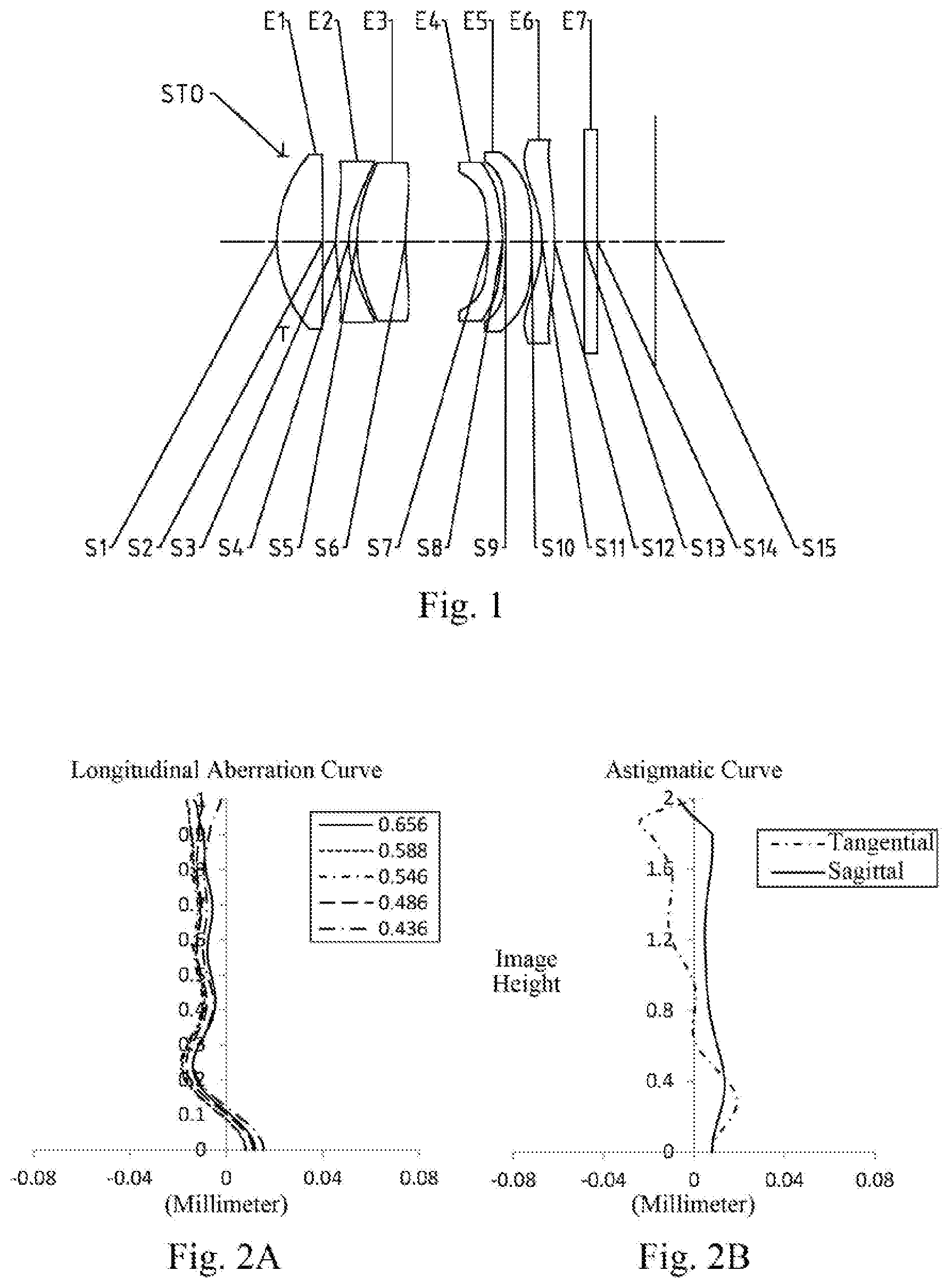
[0022] FIG. 1 is a schematic structural view of an optical imaging lens assembly according to embodiment 1 of the present disclosure;
[0023] FIGS. 2A-2D illustrate a longitudinal aberration curve, an astigmatic curve, a distortion curve and a lateral color curve of the optical imaging lens assembly according to embodiment 1, respectively;
[0024] FIG. 3 is a schematic structural view of an optical imaging lens assembly according to embodiment 2 of the present disclosure;
[0025] FIGS. 4A-4D illustrate a longitudinal aberration curve, an astigmatic curve, a distortion curve and a lateral color curve of the optical imaging lens assembly according to embodiment 2, respectively;
[0026] FIG. 5 is a schematic structural view of an optical imaging lens assembly according to embodiment 3 of the present disclosure;
[0027] FIGS. 6A-6D illustrate a longitudinal aberration curve, an astigmatic curve, a distortion curve and a lateral color curve of the optical imaging lens assembly according to embodiment 3, respectively;
[0028] FIG. 7 is a schematic structural view of an optical imaging lens assembly according to embodiment 4 of the present disclosure;
[0029] FIGS. 8A-8D illustrate a longitudinal aberration curve, an astigmatic curve, a distortion curve and a lateral color curve of the optical imaging lens assembly according to embodiment 4, respectively;
[0030] FIG. 9 is a schematic structural view of an optical imaging lens assembly according to embodiment 5 of the present disclosure;
[0031] FIGS. 10A-10D illustrate a longitudinal aberration curve, an astigmatic curve, a distortion curve and a lateral color curve of the optical imaging lens assembly according to embodiment 5, respectively;
[0032] FIG. 11 is a schematic structural view of an optical imaging lens assembly according to embodiment 6 of the present disclosure;
[0033] FIGS. 12A-12D illustrate a longitudinal aberration curve, an astigmatic curve, a distortion curve and a lateral color curve of the optical imaging lens assembly according to embodiment 6, respectively;
[0034] FIG. 13 is a schematic structural view of an optical imaging lens assembly according to embodiment 7 of the present disclosure;
[0035] FIGS. 14A-14D illustrate a longitudinal aberration curve, an astigmatic curve, a distortion curve and a lateral color curve of the optical imaging lens assembly according to embodiment 7, respectively;
[0036] FIG. 15 is a schematic structural view of an optical imaging lens assembly according to embodiment 8 of the present disclosure;
[0037] FIGS. 16A-16D illustrate a longitudinal aberration curve, an astigmatic curve, a distortion curve and a lateral color curve of the optical imaging lens assembly according to embodiment 8, respectively;
[0038] FIG. 17 is a schematic structural view of an optical imaging lens assembly according to embodiment 9 of the present disclosure; and
[0039] FIGS. 18A-18D illustrate a longitudinal aberration curve, an astigmatic curve, a distortion curve and a lateral color curve of the optical imaging lens assembly according to embodiment 9, respectively.
DETAILED DESCRIPTION OF EMBODIMENTS
[0040] For a better understanding of the present disclosure, various aspects of the present disclosure will be described in more detail with reference to the drawings. It should be understood that, these detailed descriptions are merely used for describing exemplary embodiments of the present disclosure, but not in any way for limiting the scope of the present disclosure. Throughout the specification, the same reference numerals designate the same elements. The expression "and/or" includes any and all combinations of one or more of the associated listed items.
[0041] It should be noted that, in the present specification, the expressions such as first, second and third are merely for distinguishing one feature from another feature without indicating any limitation on the features. Thus, a first lens discussed below could be referred to as a second lens or a third lens without departing from the teachings of the present disclosure.
[0042] In the accompanying drawings, for convenience of the description, thicknesses, sizes and shapes of lenses have been slightly exaggerated. Specifically, spherical or aspheric shapes shown in the accompanying drawings are shown as examples. That is, spherical or aspheric shapes are not limited to the spherical or aspheric shapes shown in the accompanying drawings. The accompanying drawings are merely examples, not strictly drawn to scale.
[0043] Herein, a paraxial region refers to a region near the optical axis. If a surface of a lens is a convex surface and the position of the convex is not defined, it indicates that the surface of the lens is convex at least in the paraxial region; and if a surface of a lens is a concave surface and the position of the concave is not defined, it indicates that the surface of the lens is concave at least in the paraxial region. The surface of each lens closest to the object side is referred to as an object-side surface, and the surface of each lens closest to the image side is referred to as an image-side surface.
[0044] It should be further understood that the terms "comprising," "including," "having", "containing" and/or "contain", when used in the specification, specify the presence of stated features, elements and/or components, but do not exclude the presence or addition of one or more other features, elements, components and/or combinations thereof. In addition, expressions, such as "at least one of," when preceding a list of features, modify the entire list of features rather than an individual element in the list. Further, the use of "may," when describing implementations of the present disclosure, refers to "one or more implementations of the present disclosure." Also, the term "exemplary" is intended to refer to an example or illustration.
[0045] Unless otherwise defined, all terms (including technical and scientific terms) used herein have the same meaning as commonly understood by those of ordinary skill in the art to which the present disclosure belongs. It will be further understood that terms, such as those defined in commonly used dictionaries, should be interpreted as having a meaning that is consistent with the meaning in the context of the relevant art and will not be interpreted in an idealized or overly formal sense, unless expressly so defined herein.
[0046] It should also be noted that, the embodiments in the present disclosure and the features in the embodiments may be combined with each other on a non-conflict basis. The present disclosure will be described in detail below with reference to the accompanying drawings and in combination with the embodiments. The features, principles, and other aspects of the present disclosure are described in detail below.
[0047] An optical imaging lens assembly according to exemplary implementations of the present disclosure may include, for example, six lenses, i.e., a first lens, a second lens, a third lens, a fourth lens, a fifth lens and sixth lens, each of which has refractive power. These six lenses are sequentially arranged from an object side to an image side along an optical axis, and there is an air gap existed between each adjacent lens.
[0048] In an exemplary implementation, the first lens may have a positive refractive power, of which an object-side surface may be a convex surface; the second lens has a positive or negative refractive power, of which an image-side surface may be a concave surface; the third lens has a positive or negative refractive power, of which an object-side surface may be a convex surface; the fourth lens has a positive or negative refractive power, of which an object-side surface may be a concave surface; the fifth lens has a positive or negative refractive power; and the sixth lens has a positive or negative refractive power, of which an object-side surface may be a concave surface.
[0049] In an exemplary implementation, the second lens may have a negative refractive power
[0050] In an exemplary implementation, an image-side surface of the third lens may be a concave surface.
[0051] In an exemplary implementation, an image-side surface of the fourth lens may be a convex surface.
[0052] In an exemplary implementation, the optical imaging lens assembly of the present disclosure may satisfy a conditional expression 1.6<f*TAN(HFOV)<2.4, wherein f is a total effective focal length of the optical imaging lens assembly, and HFOV is half of a maximal field-of-view angle of the optical imaging lens assembly. More specifically, f and HFOV may further satisfy 1.80<f*TAN(HFOV)<2.10, for example, 1.86.ltoreq.f*TAN(HFOV).ltoreq.2.08. By properly controlling the total effective focal length and maximal field-of-view angle of the optical imaging system, the optical refractive powers can be effectively and properly arranged, and chromatic aberration can be effectively corrected.
[0053] In an exemplary implementation, the optical imaging lens assembly of the present disclosure may satisfy a conditional expression 0.6<DT11/DT61<1, wherein DT11 is a maximum effective radius of the object-side surface of the first lens, and DT61 is a maximum effective radius of the object-side surface of the sixth lens. More specifically, DT11 and DT61 may further satisfy 0.70<DT11/DT61<0.90, for example, 0.74.ltoreq.DT11/DT61.ltoreq.0.87. By properly controlling the ratio of DT11 to DT61, the miniaturization of the optical system can be effectively maintained, and the utility of the optical system can be improved.
[0054] In an exemplary implementation, the optical imaging lens assembly of the present disclosure may satisfy a conditional expression TTL/f<1.05, wherein TTL is a distance along the optical axis from the object-side surface of the first lens to an imaging plane of the optical imaging lens assembly, and f is a total effective focal length of the optical imaging lens assembly. More specifically, TTL and f may further satisfy 0.95<TTL/f<1.00, for example, 0.97.ltoreq.TTL/f.ltoreq.0.99. By properly controlling the ratio of TTL to f, the imaging lens assembly may have long-focus characteristics while maintaining ultra-thin characteristics.
[0055] In an exemplary implementation, the optical imaging lens assembly of the present disclosure may satisfy a conditional expression 0.5<f1/f<1, wherein f1 is an effective focal length of the first lens, and f is the total focal length of the optical imaging lens assembly. More specifically, f1 and f may further satisfy 0.50<f1/f<0.70, for example, 0.52.ltoreq.f1/f.ltoreq.0.65. By properly controlling the ratio of f1 to f, the spherical aberration, coma, astigmatic and distortion of the system can be effectively offset.
[0056] In an exemplary implementation, the optical imaging lens assembly of the present disclosure may satisfy a conditional expression |SAG41/T34|<0.5, wherein SAG41 is a distance along the optical axis from an intersection of the object-side surface of the fourth lens and the optical axis to a vertex of an effective radius of the object-side surface of the fourth lens, and T34 is a spaced interval along the optical axis between the third lens and the fourth lens. More specifically, SAG41 and T34 may further satisfy 0.20<|SAG41/T34|<0.40, for example, 0.28.ltoreq.|SAG41/T34|.ltoreq.0.36. Properly controlling the ratio of SAG41 to T34 can effectively control the deflection of light and reduce the sensitivity of the system while reducing the size of the front end of the system.
[0057] In an exemplary implementation, the optical imaging lens assembly of the present disclosure may satisfy a conditional expression -1.5<(R5+R11)/(R1+R4)<0.5, wherein R1 is a radius of curvature of the object-side surface of the first lens, R4 is a radius of curvature of the image-side surface of the second lens, R5 is a radius of curvature of the object-side surface of the third lens, and R11 is a radius of curvature of the object-side surface of the sixth lens. More specifically, R1, R4, R5 and R11 may further satisfy -1.30<(R5+R11)/(R1+R4)<0.30, for example, -1.28.ltoreq.(R5+R11)/(R1+R4).ltoreq.0.24. By properly disposing the ratio of the sum of R1 and R4 to the sum of R5 and R11, the astigmatic of the system can be effectively reduced.
[0058] In an exemplary implementation, the optical imaging lens assembly of the present disclosure may satisfy a conditional expression -1<(1/f3+1/f6)*f2<1.5, wherein f2 is an effective focal length of the second lens, f3 is an effective focal length of the third lens, and f6 is an effective focal length of the sixth lens. More specifically, f2, f3 and f6 may further satisfy -0.70<(1/f3+1/f6)*f2<1.10, for example, -0.64.ltoreq.(1/f3+1/f6)*f2.ltoreq.1.06. By properly controlling the effective focal lengths of the second lens, the third lens, and the sixth lens, the distortion of the system can be effectively offset.
[0059] In an exemplary implementation, the optical imaging lens assembly of the present disclosure may satisfy a conditional expression (CT2+CT4)/CT3<1, wherein CT2 is a center thickness along the optical axis of the second lens, CT3 is a center thickness along the optical axis of the third lens and CT4 is a center thickness along the optical axis of the fourth lens. More specifically, CT2, CT3 and CT4 may further satisfy 0.40<(CT2+CT4)/CT3<0.70, for example, 0.44.ltoreq.(CT2+CT4)/CT3.ltoreq.0.63. By properly controlling the ratio of the sum of CT2 and CT4 to CT3, the coma and spherical aberration of the system can be effectively reduced.
[0060] In an exemplary implementation, the optical imaging lens assembly of the present disclosure may satisfy a conditional expression |f/R7-f/R8|<2.5, wherein f is a total focal length of the optical imaging lens assembly, R7 is a radius of curvature of the object-side surface of the fourth lens and R8 is a radius of curvature of an image-side surface of the fourth lens. More specifically, f, R7 and R8 may further satisfy 0.05.ltoreq.|f/R7-f/R8|.ltoreq.2.32. By properly controlling the radii of curvature of the object-side surface and image-side surface of the fourth lens and the total effective focal length of the system, the astigmatic and distortion of the system can be effectively reduced.
[0061] In an exemplary implementation, the optical imaging lens assembly of the present disclosure may satisfy a conditional expression |f123/f456|<1, wherein f123 is a combined focal length of the first lens, the second lens and the third lens, and f456 is a combined focal length of the fourth lens, the fifth lens and the sixth lens. More specifically, f123 and f456 may further satisfy 0.10<|f123/f456|<0.70, for example, 0.19.ltoreq.|f123/f456|.ltoreq.0.61. By properly controlling the ratio of f123 to f456, the optical refractive powers can be effectively and properly arranged, and chromatic aberration of the system can be effectively corrected.
[0062] In an exemplary implementation, the optical imaging lens assembly of the present disclosure may satisfy a conditional expression 0.5<CT1/(T45+CT5+T56+CT6)<1.5, wherein CT1 is a center thickness along the optical axis of the first lens, T45 is a spaced interval along the optical axis between the fourth lens and the fifth lens, CT5 is a center thickness along the optical axis of the fifth lens, T56 is a spaced interval along the optical axis between the fifth lens and the sixth lens, and CT6 is a center distance along the optical axis of the sixth lens. More specifically, CT1, T45, CT5, T56 and CT6 may further satisfy 0.60<CT1/(T45+CT5+T56+CT6)<1.30, for example, 0.68<CT1/(T45+CT5+T56+CT6).ltoreq.1.27. By properly controlling CT1, T45, CT5, T56 and CT6, the tolerance sensitivity of the optical imaging system can be reduced while reducing the size of the rear end of the optical imaging system, thereby improving the imaging quality.
[0063] In an exemplary implementation, the optical imaging lens assembly of the present disclosure may satisfy a conditional expression 1<f1/.SIGMA.CT<2, wherein f1 is an effective focal length of the first lens, and .SIGMA.CT is sum of center thicknesses along the optical axis of the first lens to the sixth lens. More specifically, .SIGMA.CT and f1 may further satisfy 1.24.ltoreq.f1/.SIGMA.CT.ltoreq.1.57. Satisfying the conditional expression 1<f1/.SIGMA.CT<2 is beneficial to ensure the miniaturization of the lens assembly. By properly controlling the distribution of the center thickness of each lens, the deflection of light may tend to ease, the system sensitivity may be reduced, and at the same time, the astigmatic, distortion and chromatic aberration of the system may be reduced.
[0064] In an exemplary implementation, the optical imaging lens assembly of the present disclosure may satisfy a conditional expression (T23+T45)/T34<0.4, wherein T23 is a spaced interval along the optical axis between the second lens and the third lens, T34 is a spaced interval along the optical axis between the third lens and the fourth lens, and T45 is a spaced interval along the optical axis between the fourth lens and the fifth lens. More specifically, T23, T34 and T45 may further satisfy 0<(T23+T45)/T34<0.30, for example, 0.1.ltoreq.(T23+T45)/T34.ltoreq.0.28. By properly controlling T23, T34 and T45, a good processing gap between the optical lenses can be ensured, and an appropriate deflection of light in the system can also be ensured.
[0065] In an exemplary implementation, the optical imaging lens assembly of the present disclosure may satisfy a conditional expression 4.5.ltoreq.f/f1/TAN(HFOV)<6.5, wherein, f is a total effective focal length of the optical imaging lens assembly, f1 is an effective focal length of the first lens, and HFOV is half of a maximal field-of-view angle of the optical imaging lens assembly. More specifically, f, f1 and HFOV may further satisfy 4.55.ltoreq.f/f1/TAN(HFOV).ltoreq.6.14. By controlling the total effective focal length of the optical imaging lens assembly, the effective focal length of the first lens, and half of the maximal field-of-view angle of the optical imaging system, the chromatic aberration of the optical system can be effectively reduced, the deflection angle of light at the front end of the optical system can be reduced, and the sensitivity can be reduced.
[0066] In an exemplary implementation, the optical imaging lens assembly of the present disclosure may further include at least one stop to improve the imaging quality of the optical imaging lens assembly. The stop may be disposed between the object side and the first lens. Alternatively, the optical imaging lens assembly described above may further include an optical filter for correcting chromatic aberration and/or a protective glass for protecting a photosensitive element on the imaging plane.
[0067] The optical imaging lens assembly according to the above implementations of the present disclosure may employ a plurality of lenses, such as six lenses as described above. By properly disposing the refractive power, the surface shape, the center thickness of each lens, and spaced distances along the optical axis between the lenses, the size and the sensitivity of the optical imaging lens assembly can be effectively reduced, and the processability of the optical imaging lens assembly can be improved, such that the optical imaging lens assembly is more beneficial for production processing and can be applied to portable electronic products. The optical imaging lens assembly configured as above also has advantageous effect such as long-focus, high resolution, high relative brightness and excellent imaging quality, etc.
[0068] In the implementations of the present disclosure, at least one of the surfaces of each lens is aspheric. The aspheric lens is characterized by a continuous change in curvature from the center of the lens to the periphery of the lens. Unlike a spherical lens having a constant curvature from the center of the lens to the periphery of the lens, the aspheric lens has a better radius of curvature characteristic, and has the advantages of improving distortion aberration and improving astigmatic aberration. By using an aspheric lens, the aberrations that occur during imaging can be eliminated as much as possible, and thus improving imaging quality.
[0069] However, it will be understood by those skilled in the art that the number of lenses constituting the optical imaging lens assembly can be varied to achieve the various results and advantages described in this specification without departing from the technical solution claimed by the present disclosure. For example, although the implementation are described by taking six lenses as an example, the optical imaging lens assembly is not limited to including six lenses. The optical imaging lens assembly may also include other numbers of lenses if desired. Specific embodiments applicable to the optical imaging lens assembly of the above implementations will be further described below with reference to the accompanying drawings.
Embodiment 1
[0070] An optical imaging lens assembly according to embodiment 1 of the present disclosure is described below with reference to FIG. 1 to FIG. 2D. FIG. 1 is a schematic structural view of the optical imaging lens assembly according to embodiment 1 of the present disclosure.
[0071] As shown in FIG. 1, the optical imaging lens assembly according to an exemplary implementation includes, sequentially from an object side to an image side along an optical axis: a stop STO, a first lens E1, a second lens E2, a third lens E3, a fourth lens E4, a fifth lens E5, a sixth lens E6, an optical filter E7 and an imaging plane S15.
[0072] The first lens E1 has a positive refractive power, an object-side surface S1 thereof is a convex surface, and an image-side surface S2 thereof is a convex surface. The second lens E2 has a negative refractive power, an object-side surface S3 thereof is a convex surface, and an image-side surface S4 thereof is a concave surface. The third lens E3 has a positive refractive power, an object-side surface S5 thereof is a convex surface, and an image-side surface S6 thereof is a concave surface. The fourth lens E4 has a positive refractive power, an object-side surface S7 thereof is a concave surface, and an image-side surface S8 thereof is a convex surface. The fifth lens E5 has a negative refractive power, an object-side surface S9 thereof is a concave surface, and an image-side surface S10 thereof is a concave surface. The sixth lens E6 has a negative refractive power, an object-side surface S11 thereof is a concave surface, and an image-side surface S12 thereof is a convex surface. The optical filter E7 has an object-side surface S13 and an image-side surface S14. Light from the object sequentially passes through the respective surfaces S1 to S14 and is finally imaged on the imaging plane S15.
[0073] Table 1 shows surface type, radius of curvature, thickness, material and conic coefficient of each lens of the optical imaging lens assembly in embodiment 1, wherein the units for the radius of curvature and the thickness are millimeter (mm).
TABLE-US-00001 TABLE 1 Material Surface Surface Radius of Thick- Refractive Abbe Conic number type curvature ness index number coefficient OBJ spherical infinite infinite STO spherical infinite -0.1000 S1 aspheric 2.1062 0.7235 1.53 56.0 0.4710 S2 aspheric -1171.8634 0.2133 -99.0000 S3 aspheric 2.6841 0.2000 1.61 26.6 -19.6446 S4 aspheric 1.2682 0.1316 -3.9870 S5 aspheric 2.1755 0.7697 1.53 56.0 -2.3129 S6 aspheric 4.8852 1.3133 -52.4168 S7 aspheric -3.1570 0.2269 1.53 56.0 5.8436 S8 aspheric -1.4944 0.0500 -15.9801 S9 aspheric -5.0756 0.4103 1.61 26.6 14.2325 S10 aspheric 226.0494 0.1582 99.0000 S11 aspheric -2.5295 0.2000 1.53 56.0 -4.7275 S12 aspheric -15.8143 0.4727 -99.0000 S13 spherical infinite 0.2100 1.52 64.2 S14 spherical infinite 0.9206 S15 spherical infinite
[0074] As can be seen from Table 1, the object-side surface and the image-side surface of any one of the first lens E1 to the sixth lens E6 are aspheric. In this embodiment, the surface shape x of each aspheric lens can be defined by using, but not limited to, the following aspheric formula:
x = c h 2 1 + 1 - ( k + 1 ) c 2 h 2 + A i h i ( 1 ) ##EQU00001##
[0075] Here, x is the sag--the axis-component of the displacement of the aspheric surface from the aspheric vertex, when the surface is at height h from the optical axis; c is the paraxial curvature of the aspheric surface, c=1/R (that is, the paraxial curvature c is reciprocal of the radius of curvature R in the above Table 1); k is the conic coefficient (given in the above Table 1); Ai is a correction coefficient for the i-th order of the aspheric surface. Table 2 below shows high-order coefficients A.sub.4, A.sub.6, A.sub.8, A.sub.10, A.sub.12, A.sub.16, A.sub.18 and A.sub.20 applicable to each aspheric surface S1-S12 in embodiment 1.
TABLE-US-00002 TABLE 2 Surface number A4 A6 A8 A10 A12 S1 -1.7205E-03 -4.7566E-02 1.3985E-01 -2.4609E-01 2.5964E-01 S2 -8.3283E-03 2.3740E-02 -2.1831E-02 -5.9105E-02 1.6434E-01 S3 -9.3808E-02 2.6467E-01 -7.6005E-01 1.2383E+00 -1.1873E+00 S4 -8.1530E-02 6.1018E-01 -2.0904E+00 4.1122E+00 -5.0163E+00 S5 -4.2601E-02 2.7733E-01 -8.6266E-01 1.5412E+00 -1.7007E+00 S6 5.7773E-03 -3.0013E-02 -5.5318E-02 1.8122E-01 -2.7366E-01 S7 1.2398E-01 1.1246E-01 -1.5924E+00 3.9443E+00 -6.5142E+00 S8 2.8608E-01 -1.8114E-01 -8.6469E-01 1.8411E+00 -2.4494E+00 S9 4.3829E-01 -1.3119E+00 2.9195E+00 -5.3486E+00 6.4876E+00 S10 -2.8454E-01 3.1519E-01 -1.2760E-01 -4.0243E-01 7.3189E-01 S11 -2.8504E-01 3.9817E-01 9.8816E-02 -7.8600E-01 9.2454E-01 S12 -1.6187E-01 2.7572E-01 -2.1379E-01 7.2464E-02 5.7430E-04 Surface number A14 A16 A18 A20 S1 -1.6735E-01 6.4381E-02 -1.3581E-02 1.2117E-03 S2 -1.7199E-01 9.2404E-02 -2.5305E-02 2.8034E-03 S3 6.6286E-01 -1.9940E-01 2.5195E-02 -1.0682E-04 S4 3.8478E+00 -1.8087E+00 4.7816E-01 -5.4739E-02 S5 1.1721E+00 -4.8838E-01 1.1206E-01 -1.0840E-02 S6 2.5470E-01 -1.4556E-01 4.5663E-02 -5.9208E-03 S7 7.0526E+00 -4.6611E+00 1.7046E+00 -2.6369E-01 S8 2.5994E+00 -1.8308E+00 7.0650E-01 -1.1222E-01 S9 -4.7833E+00 2.0421E+00 -4.6019E-01 4.1877E-02 S10 -5.6606E-01 2.3574E-01 -5.2097E-02 4.8616E-03 S11 -5.4274E-01 1.7718E-01 -3.0785E-02 2.2273E-03 S12 -7.5409E-03 2.1435E-03 -2.4594E-04 1.0195E-05
[0076] Table 3 shows effective focal lengths f1 to f6 of lenses, the total effective focal length f, a total optical length TTL (i.e., a distance along the optical axis from the center of the object-side surface S1 of the first lens E1 to the imaging plane S15), and half of a maximal field-of-view angle HFOV of the optical imaging lens assembly in embodiment 1.
TABLE-US-00003 TABLE 3 f1 (mm) 3.94 f2 (mm) -4.15 f3 (mm) 6.69 f4 (mm) 5.07 f5 (mm) -8.10 f6 (mm) -5.67 f (mm) 6.18 TIT (mm) 6.00 HFOV (.degree.) 17.7
[0077] FIG. 2A illustrates a longitudinal aberration curve of the optical imaging lens assembly according to embodiment 1, representing deviations of focal points converged by light of different wavelengths after passing through the optical imaging lens assembly. FIG. 2B illustrates an astigmatic curve of the optical imaging lens assembly according to embodiment 1, representing a curvature of a tangential plane and a curvature of a sagittal plane. FIG. 2C illustrates a distortion curve of the optical imaging lens assembly according to embodiment 1, representing amounts of distortion at different image heights. FIG. 2D illustrates a lateral color curve of the optical imaging lens assembly according to embodiment 1, representing deviations of different image heights on an imaging plane after light passes through the optical imaging lens assembly. It can be seen from FIG. 2A to FIG. 2D that the optical imaging lens assembly provided in embodiment 1 can achieve good image quality.
Embodiment 2
[0078] An optical imaging lens assembly according to embodiment 2 of the present disclosure is described below with reference to FIG. 3 to FIG. 4D. In this embodiment and the following embodiments, for the purpose of brevity, the description of parts similar to those in embodiment 1 will be omitted. FIG. 3 is a schematic structural view of the optical imaging lens assembly according to embodiment 2 of the present disclosure.
[0079] As shown in FIG. 3, the optical imaging lens assembly according to an exemplary implementation includes, sequentially from an object side to an image side along an optical axis: a stop STO, a first lens E1, a second lens E2, a third lens E3, a fourth lens E4, a fifth lens E5, a sixth lens E6, an optical filter E7 and an imaging plane S15.
[0080] The first lens E1 has a positive refractive power, an object-side surface S1 thereof is a convex surface, and an image-side surface S2 thereof is a concave surface. The second lens E2 has a negative refractive power, an object-side surface S3 thereof is a convex surface, and an image-side surface S4 thereof is a concave surface. The third lens E3 has a positive refractive power, an object-side surface S5 thereof is a convex surface, and an image-side surface S6 thereof is a concave surface. The fourth lens E4 has a positive refractive power, an object-side surface S7 thereof is a concave surface, and an image-side surface S8 thereof is a convex surface. The fifth lens E5 has a negative refractive power, an object-side surface S9 thereof is a concave surface, and an image-side surface S10 thereof is a convex surface. The sixth lens E6 has a negative refractive power, an object-side surface S11 thereof is a concave surface, and an image-side surface S12 thereof is a convex surface. The optical filter E7 has an object-side surface S13 and an image-side surface S14. Light from the object sequentially passes through the respective surfaces S1 to S14 and is finally imaged on the imaging plane S15.
[0081] Table 4 shows surface type, radius of curvature, thickness, material and conic coefficient of each lens of the optical imaging lens assembly in embodiment 2, wherein the units for the radius of curvature and the thickness are millimeter (mm). Table 5 shows high-order coefficients applicable to each aspheric surface in embodiment 2, wherein the surface type of each aspheric surface may be defined by the formula (1) given above in embodiment 1. Table 6 shows effective focal lengths f1 to f6 of lenses, the total effective focal length f, a total optical length TTL, and half of a maximal field-of-view angle HFOV of the optical imaging lens assembly in embodiment 2.
TABLE-US-00004 TABLE 4 Material Surface Surface Radius of Refractive Abbe Conic number type curvature Thickness index number coefficient OBJ spherical infinite infinite STO spherical infinite -0.1000 S1 aspheric 2.1014 0.7158 1.53 56.0 0.4689 S2 aspheric 251.2571 0.2098 -99.0000 S3 aspheric 2.8518 0.2000 1.61 26.6 -19.6319 S4 aspheric 1.3042 0.1250 -3.9836 S5 aspheric 2.1690 0.7894 1.53 56.0 -2.3107 S6 aspheric 5.0573 1.3067 -51.5894 S7 aspheric -3.1640 0.2267 1.53 56.0 5.8396 S8 aspheric -1.4942 0.0522 -15.6285 S9 aspheric -5.0918 0.4189 1.61 26.6 14.3403 S10 aspheric -1000.0000 0.1630 99.0000 S11 aspheric -2.4150 0.2000 1.53 56.0 -4.4190 S12 aspheric -10.9553 0.4672 -99.0000 S13 spherical infinite 0.2100 1.52 64.2 S14 spherical infinite 0.9151 S15 spherical infinite
TABLE-US-00005 TABLE 5 Surface number A4 A6 A8 A10 A12 S1 -5.4933E-03 -2.6665E-02 7.4853E-02 -1.2747E-01 1.2624E-01 S2 -6.9836E-03 1.4461E-02 6.1249E-03 -1.0389E-01 2.0573E-01 S3 -9.4330E-02 2.3599E-01 -6.2211E-01 9.4868E-01 -8.3945E-01 S4 -6.8275E-02 5.0621E-01 -1.7309E+00 3.4251E+00 -4.2149E+00 S5 -3.3549E-02 2.2641E-01 -7.3015E-01 1.3639E+00 -1.5760E+00 S6 4.8301E-03 -3.7926E-02 -9.4547E-03 8.0483E-02 -1.4163E-01 S7 1.1401E-01 1.0671E-01 -1.4164E+00 3.0918E+00 -4.4143E+00 S8 2.6949E-01 6.0845E-02 -1.9478E+00 4.2119E+00 -5.4601E+00 S9 4.3404E-01 -1.0776E+00 1.9483E+00 -3.2617E+00 3.7447E+00 S10 -3.0591E-01 4.2108E-01 -3.8040E-01 -1.6861E-02 3.4265E-01 S11 -2.9328E-01 4.6379E-01 -1.1625E-01 -4.2474E-01 5.8048E-01 S12 -1.3777E-01 2.4269E-01 -2.0034E-01 8.3992E-02 -1.7375E-02 Surface number A14 A16 A18 A20 S1 -7.3498E-02 2.4037E-02 -3.8869E-03 2.1536E-04 S2 -1.9443E-01 9.8895E-02 -2.5964E-02 2.7585E-03 S3 4.0518E-01 -8.1800E-02 -5.2275E-03 3.3002E-03 S4 3.2523E+00 -1.5295E+00 4.0233E-01 -4.5649E-02 S5 1.1304E+00 -4.8596E-01 1.1415E-01 -1.1237E-02 S6 1.4460E-01 -8.9219E-02 2.9731E-02 -4.0302E-03 S7 4.2430E+00 -2.5593E+00 8.7069E-01 -1.2650E-01 S8 4.9483E+00 -2.9501E+00 1.0073E+00 -1.4729E-01 S9 -2.5416E+00 9.4323E-01 -1.6624E-01 9.0052E-03 S10 -3.1042E-01 1.3247E-01 -2.8989E-02 2.6719E-03 S11 -3.4940E-01 1.1350E-01 -1.9388E-02 1.3707E-03 S12 1.9578E-03 -3.4503E-04 7.8705E-05 -6.6536E-06
TABLE-US-00006 TABLE 6 f1 (mm) 3.97 f2 (mm) -4.13 f3 (mm) 6.50 f4 (mm) 5.06 f5 (mm) -8.35 f6 (mm) -5.85 f (mm) 6.08 TTL (mm) 6.00 HFOV (.degree.) 18.0
[0082] FIG. 4A illustrates a longitudinal aberration curve of the optical imaging lens assembly according to embodiment 2, representing deviations of focal points converged by light of different wavelengths after passing through the optical imaging lens assembly. FIG. 4B illustrates an astigmatic curve of the optical imaging lens assembly according to embodiment 2, representing a curvature of a tangential plane and a curvature of a sagittal plane. FIG. 4C illustrates a distortion curve of the optical imaging lens assembly according to embodiment 2, representing amounts of distortion at different image heights. FIG. 4D illustrates a lateral color curve of the optical imaging lens assembly according to embodiment 2, representing deviations of different image heights on an imaging plane after light passes through the optical imaging lens assembly. It can be seen from FIG. 4A to FIG. 4D that the optical imaging lens assembly provided in embodiment 2 can achieve good image quality.
Embodiment 3
[0083] An optical imaging lens assembly according to embodiment 3 of the present disclosure is described below with reference to FIG. 5 to FIG. 6D. FIG. 5 is a schematic structural view of the optical imaging lens assembly according to embodiment 3 of the present disclosure.
[0084] As shown in FIG. 5, the optical imaging lens assembly according to an exemplary implementation includes, sequentially from an object side to an image side along an optical axis: a stop STO, a first lens E1, a second lens E2, a third lens E3, a fourth lens E4, a fifth lens E5, a sixth lens E6, an optical filter E7 and an imaging plane S15.
[0085] The first lens E1 has a positive refractive power, an object-side surface S1 thereof is a convex surface, and an image-side surface S2 thereof is a convex surface. The second lens E2 has a negative refractive power, an object-side surface S3 thereof is a convex surface, and an image-side surface S4 thereof is a concave surface. The third lens E3 has a positive refractive power, an object-side surface S5 thereof is a convex surface, and an image-side surface S6 thereof is a concave surface. The fourth lens E4 has a negative refractive power, an object-side surface S7 thereof is a concave surface, and an image-side surface S8 thereof is a convex surface. The fifth lens E5 has a positive refractive power, an object-side surface S9 thereof is a convex surface, and an image-side surface S10 thereof is a concave surface. The sixth lens E6 has a negative refractive power, an object-side surface S11 thereof is a concave surface, and an image-side surface S12 thereof is a concave surface. The optical filter E7 has an object-side surface S13 and an image-side surface S14. Light from the object sequentially passes through the respective surfaces S1 to S14 and is finally imaged on the imaging plane S15.
[0086] Table 7 shows surface type, radius of curvature, thickness, material and conic coefficient of each lens of the optical imaging lens assembly in embodiment 3, wherein the units for the radius of curvature and the thickness are millimeter (mm). Table 8 shows high-order coefficients applicable to each aspheric surface in embodiment 3, wherein the surface type of each aspheric surface may be defined by the formula (1) given above in embodiment 1. Table 9 shows effective focal lengths f1 to f6 of lenses, the total effective focal length f, a total optical length TTL, and half of a maximal field-of-view angle HFOV of the optical imaging lens assembly in embodiment 3.
TABLE-US-00007 TABLE 7 Material Conic Surface Surface Radius of Thick- Refractive Abbe coeffi- number type curvature ness index number cient OBJ spherical infinite infinite STO spherical infinite -0.1000 S1 aspheric 2.1229 0.7174 1.53 56.0 0.4677 S2 aspheric -471.1521 0.2063 -99.0000 S3 aspheric 3.0232 0.2000 1.61 26.6 -20.3839 S4 aspheric 1.2732 0.1168 -3.8910 S5 aspheric 2.0184 0.9046 1.53 56.0 -2.3329 S6 aspheric 5.2820 1.2799 -52.2950 S7 aspheric -3.1891 0.2000 1.53 56.0 5.9964 S8 aspheric -3.2783 0.1353 -18.6165 S9 aspheric 5.8282 0.3000 1.61 26.6 -99.0000 S10 aspheric 16.9852 0.1479 -89.6703 S11 aspheric -4.5222 0.2000 1.53 56.0 -5.5553 S12 aspheric 11.2153 0.4669 -83.6612 S13 spherical infinite 0.2100 1.52 64.2 S14 spherical infinite 0.9148 S15 spherical infinite
TABLE-US-00008 TABLE 8 Surface number A4 A6 A8 A10 A12 A14 A16 A18 A20 S1 -6.6986E-03 -2.5290E-02 8.2769E-02 -1.6818E-01 2.0896E-01 -1.6355E-01 7.8833E-02 -2.1431E-02 2.5205E-03 S2 -6.3042E-03 3.1756E-02 -8.5286E-02 1.2199E-01 -1.1439E-01 7.3554E-02 -3.0620E-02 7.1133E-03 -6.4710E-04 S3 -9.7117E-02 2.1923E-01 -5.7536E-01 1.0044E+00 -1.2161E+00 1.0223E+00 -5.6425E-01 1.8116E-01 -2.5309E-02 S4 -4.4370E-02 3.5605E-01 -1.3066E+00 3.1039E+00 -5.1406E+00 5.7191E+00 -3.9902E+00 1.5589E+00 -2.5833E-01 S5 -2.0935E-02 1.7334E-01 -7.1470E-01 1.9935E+00 -3.7639E+00 4.5450E+00 -3.3178E+00 1.3265E+00 -2.2217E-01 S6 2.1389E-04 -3.7098E-02 3.3441E-03 7.5947E-02 -1.9638E-01 2.6740E-01 -2.1330E-01 9.3102E-02 -1.7139E-02 S7 2.8154E-01 -1.1295E+00 2.2975E+00 -3.0167E+00 1.2889E+00 1.9937E+00 -3.3952E+00 2.0594E+00 -4.6750E-01 S8 5.9088E-01 -2.4013E+00 5.8994E+00 -9.8106E+00 1.0813E+01 -7.7821E+00 3.5269E+00 -9.1371E-01 1.0294E-01 S9 3.1769E-01 -1.3344E+00 2.6511E+00 -3.3105E+00 2.5262E+00 -1.1027E+00 2.2536E-01 -2.6145E-03 -4.1749E-03 S10 -9.4332E-02 -4.5138E-02 -1.7765E-01 8.3610E-01 -1.3739E+00 1.2005E+00 -5.9313E-01 1.5612E-01 -1.7000E-02 S11 -3.0859E-01 6.6574E-01 -8.5328E-01 8.6680E-01 -6.6078E-01 3.4181E-01 -1.0997E-01 1.9699E-02 -1.5007E-03 S12 -2.4415E-01 4.5418E-01 -5.1055E-01 3.7065E-01 -1.7514E-01 5.0009E-02 -7.0094E-03 1.3583E-04 4.5060E-05
TABLE-US-00009 TABLE 9 f1 (mm) 3.96 f2 (mm) -3.75 f3 (mm) 5.58 f4 (mm) -1001.23 f5 (mm) 14.34 f6 (mm) -6.01 f (mm) 6.08 TTL (mm) 6.00 HFOV (.degree.) 18.2
[0087] FIG. 6A illustrates a longitudinal aberration curve of the optical imaging lens assembly according to embodiment 3, representing deviations of focal points converged by light of different wavelengths after passing through the optical imaging lens assembly. FIG. 6B illustrates an astigmatic curve of the optical imaging lens assembly according to embodiment 3, representing a curvature of a tangential plane and a curvature of a sagittal plane. FIG. 6C illustrates a distortion curve of the optical imaging lens assembly according to embodiment 3, representing amounts of distortion at different image heights. FIG. 6D illustrates a lateral color curve of the optical imaging lens assembly according to embodiment 3, representing deviations of different image heights on an imaging plane after light passes through the optical imaging lens assembly. It can be seen from FIG. 6A to FIG. 6D that the optical imaging lens assembly provided in embodiment 3 can achieve good image quality.
Embodiment 4
[0088] An optical imaging lens assembly according to embodiment 4 of the present disclosure is described below with reference to FIG. 7 to FIG. 8D. FIG. 7 is a schematic structural view of the optical imaging lens assembly according to embodiment 4 of the present disclosure.
[0089] As shown in FIG. 7, the optical imaging lens assembly according to an exemplary implementation includes, sequentially from an object side to an image side along an optical axis: a stop STO, a first lens E1, a second lens E2, a third lens E3, a fourth lens E4, a fifth lens E5, a sixth lens E6, an optical filter E7 and an imaging plane S15.
[0090] The first lens E1 has a positive refractive power, an object-side surface S1 thereof is a convex surface, and an image-side surface S2 thereof is a convex surface. The second lens E2 has a negative refractive power, an object-side surface S3 thereof is a convex surface, and an image-side surface S4 thereof is a concave surface. The third lens E3 has a negative refractive power, an object-side surface S5 thereof is a convex surface, and an image-side surface S6 thereof is a concave surface. The fourth lens E4 has a positive refractive power, an object-side surface S7 thereof is a concave surface, and an image-side surface S8 thereof is a convex surface. The fifth lens E5 has a negative refractive power, an object-side surface S9 thereof is a concave surface, and an image-side surface S10 thereof is a convex surface. The sixth lens E6 has a negative refractive power, an object-side surface S11 thereof is a concave surface, and an image-side surface S12 thereof is a concave surface. The optical filter E7 has an object-side surface S13 and an image-side surface S14. Light from the object sequentially passes through the respective surfaces S1 to S14 and is finally imaged on the imaging plane S15.
[0091] Table 10 shows surface type, radius of curvature, thickness, material and conic coefficient of each lens of the optical imaging lens assembly in embodiment 4, wherein the units for the radius of curvature and the thickness are millimeter (mm). Table 11 shows high-order coefficients applicable to each aspheric surface in embodiment 4, wherein the surface type of each aspheric surface may be defined by the formula (1) given above in embodiment 1. Table 12 shows effective focal lengths f1 to f6 of lenses, the total effective focal length f, a total optical length TTL, and half of a maximal field-of-view angle HFOV of the optical imaging lens assembly in embodiment 4.
TABLE-US-00010 TABLE 10 Material Conic Surface Surface Radius of Thick- Refractive Abbe coeffi- number type curvature ness index number cient OBJ spherical infinite infinite STO spherical infinite -0.1000 S1 aspheric 2.0098 0.8859 1.53 56.0 0.4421 S2 aspheric -17.4620 0.0682 99.0000 S3 aspheric 3.1104 0.2000 1.61 26.6 -26.4405 S4 aspheric 1.5731 0.1593 -3.1641 S5 aspheric 3.1552 0.6865 1.53 56.0 0.3792 S6 aspheric 2.8993 1.2996 -21.6120 S7 aspheric -3.5032 0.2331 1.53 56.0 7.4154 S8 aspheric -1.5002 0.1293 -19.3453 S9 aspheric -6.2176 0.3000 1.61 26.6 19.0987 S10 aspheric -14.7306 0.0693 91.6655 S11 aspheric -4.3498 0.2000 1.53 56.0 -63.2884 S12 aspheric 7.6550 0.5542 20.7263 S13 spherical infinite 0.2100 1.52 64.2 S14 spherical infinite 1.0047 S15 spherical infinite
TABLE-US-00011 TABLE 11 Surface number A4 A6 A8 A10 A12 A14 A16 A18 A20 S1 -9.3490E-03 -3.6196E-02 1.2064E-01 -2.2522E-01 2.5293E-01 -1.7765E-01 7.6469E-02 -1.8524E-02 1.9409E-03 S2 -1.9266E-01 6.1942E-01 -1.2058E+00 1.5754E+00 -1.3890E+00 8.1366E-01 -3.0300E-01 6.4826E-02 -6.0456E-03 S3 -1.2226E-01 3.0680E-01 -9.1032E-01 1.7616E+00 -2.1348E+00 1.6293E+00 -7.6642E-01 2.0409E-01 -2.3616E-02 S4 1.6462E-01 -2.3784E-01 -8.8045E-01 3.7504E+00 -6.5020E+00 6.4634E+00 -3.8507E+00 1.2838E+00 -1.8411E-01 S5 1.3859E-01 -1.3025E-01 -6.8620E-01 2.3862E+00 -3.7588E+00 3.5466E+00 -2.0736E+00 6.9485E-01 -1.0145E-01 S6 7.1653E-02 -1.5298E-01 7.4639E-02 2.1847E-01 -5.4481E-01 5.8990E-01 -3.5516E-01 1.1436E-01 -1.5276E-02 S7 1.5881E-01 -5.9749E-02 -3.2684E-01 -1.2005E+00 5.4682E+00 -9.4387E+00 8.7040E+00 -4.2265E+00 8.4615E-01 S8 -2.1842E-02 1.4921E+00 -6.1066E+00 1.1997E+01 -1.4609E+01 1.1496E+01 -5.6341E+00 1.5475E+00 -1.8030E-01 S9 2.7609E-01 -2.8840E-01 -3.6545E-01 5.8284E-01 -5.0618E-02 -3.9860E-01 3.5625E-01 -1.4319E-01 2.4190E-02 S10 -2.7807E-01 6.4453E-01 -1.5454E+00 2.3317E+00 -2.2164E+00 1.3522E+00 -5.2618E-01 1.2034E-01 -1.2286E-02 S11 -1.6721E-01 -3.9015E-02 5.9769E-01 -7.3043E-01 3.9942E-01 -9.8818E-02 3.3773E-03 2.9451E-03 -3.9147E-04 S12 1.9602E-02 -4.4330E-01 1.2789E+00 -1.9690E+00 1.8458E+00 -1.0820E+00 3.8732E-01 -7.7301E-02 6.5780E-03
TABLE-US-00012 TABLE 12 f1 (mm) 3.43 f2 (mm) -5.46 f3 (mm) -1007.79 f4 (mm) 4.72 f5 (mm) -17.80 f6 (mm) -5.17 f (mm) 6.08 TTL (mm) 6.00 HFOV (.degree.) 17.0
[0092] FIG. 8A illustrates a longitudinal aberration curve of the optical imaging lens assembly according to embodiment 4, representing deviations of focal points converged by light of different wavelengths after passing through the optical imaging lens assembly. FIG. 8B illustrates an astigmatic curve of the optical imaging lens assembly according to embodiment 4, representing a curvature of a tangential plane and a curvature of a sagittal plane. FIG. 8C illustrates a distortion curve of the optical imaging lens assembly according to embodiment 4, representing amounts of distortion at different image heights. FIG. 8D illustrates a lateral color curve of the optical imaging lens assembly according to embodiment 4, representing deviations of different image heights on an imaging plane after light passes through the optical imaging lens assembly. It can be seen from FIG. 8A to FIG. 8D that the optical imaging lens assembly provided in embodiment 4 can achieve good image quality.
Embodiment 5
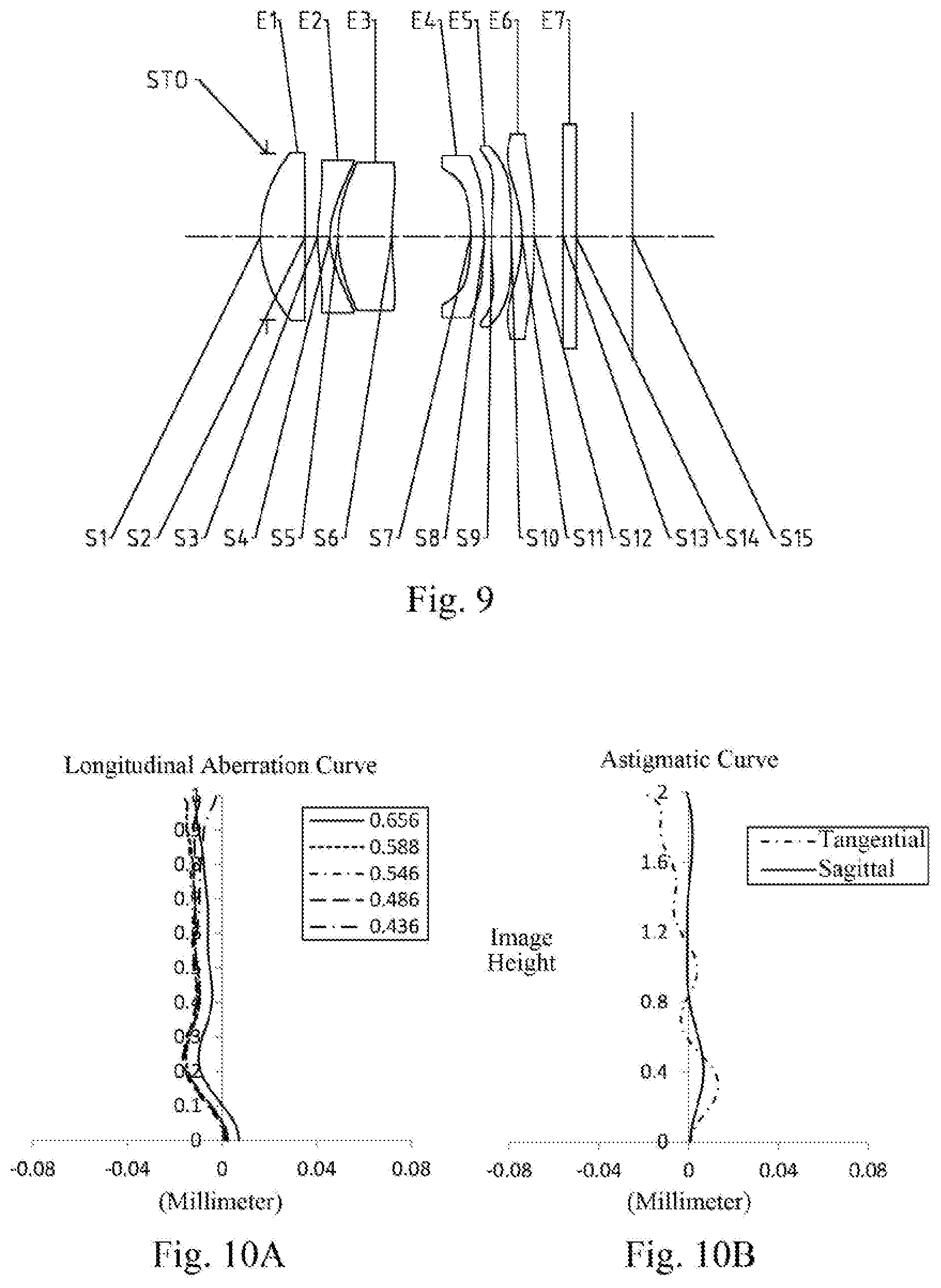
[0093] An optical imaging lens assembly according to embodiment 5 of the present disclosure is described below with reference to FIG. 9 to FIG. 10D. FIG. 9 is a schematic structural view of the optical imaging lens assembly according to embodiment 5 of the present disclosure.
[0094] As shown in FIG. 9, the optical imaging lens assembly according to an exemplary implementation includes, sequentially from an object side to an image side along an optical axis: a stop STO, a first lens E1, a second lens E2, a third lens E3, a fourth lens E4, a fifth lens E5, a sixth lens E6, an optical filter E7 and an imaging plane S15.
[0095] The first lens E1 has a positive refractive power, an object-side surface S1 thereof is a convex surface, and an image-side surface S2 thereof is a concave surface. The second lens E2 has a negative refractive power, an object-side surface S3 thereof is a convex surface, and an image-side surface S4 thereof is a concave surface. The third lens E3 has a positive refractive power, an object-side surface S5 thereof is a convex surface, and an image-side surface S6 thereof is a concave surface. The fourth lens E4 has a positive refractive power, an object-side surface S7 thereof is a concave surface, and an image-side surface S8 thereof is a convex surface. The fifth lens E5 has a positive refractive power, an object-side surface S9 thereof is a convex surface, and an image-side surface S10 thereof is a concave surface. The sixth lens E6 has a negative refractive power, an object-side surface S11 thereof is a concave surface, and an image-side surface S12 thereof is a convex surface. The optical filter E7 has an object-side surface S13 and an image-side surface S14. Light from the object sequentially passes through the respective surfaces S1 to S14 and is finally imaged on the imaging plane S15.
[0096] Table 13 shows surface type, radius of curvature, thickness, material and conic coefficient of each lens of the optical imaging lens assembly in embodiment 5, wherein the units for the radius of curvature and the thickness are millimeter (mm). Table 14 shows high-order coefficients applicable to each aspheric surface in embodiment 5, wherein the surface type of each aspheric surface may be defined by the formula (1) given above in embodiment 1. Table 15 shows effective focal lengths f1 to f6 of lenses, the total effective focal length f, a total optical length TTL, and half of a maximal field-of-view angle HFOV of the optical imaging lens assembly in embodiment 5.
TABLE-US-00013 TABLE 13 Sur- face Material Conic num- Surface Radius of Thick- Refractive Abbe coeffi- ber type curvature ness index number cient OBJ spherical infinite infinite STO spherical infinite -0.1000 S1 aspheric 2.1179 0.7201 1.53 56.0 0.4705 S2 aspheric 1483.6488 0.1993 99.0000 S3 aspheric 2.7483 0.2000 1.61 26.6 -19.9544 S4 aspheric 1.2463 0.1290 -3.9414 S5 aspheric 2.1001 0.8714 1.53 56.0 -2.2630 S6 aspheric 5.3237 1.2686 -56.2994 S7 aspheric -3.1826 0.2202 1.53 56.0 6.0675 S8 aspheric -2.5219 0.1155 -17.7174 S9 aspheric 13.6949 0.3181 1.61 26.6 -84.7599 S10 aspheric 17.4816 0.1681 88.0388 S11 aspheric -3.4015 0.2000 1.53 56.0 -4.5127 S12 aspheric -164.9617 0.4659 -99.0000 S13 spherical infinite 0.2100 1.52 64.2 S14 spherical infinite 0.9137 S15 spherical infinite
TABLE-US-00014 TABLE 14 Surface number A4 A6 A8 A10 A12 A14 A16 A18 A20 S1 -3.6878E-03 -3.8728E-02 1.2155E-01 -2.3343E-01 2.7286E-01 -1.9853E-01 8.8043E-02 -2.1886E-02 2.3504E-03 S2 -6.4552E-03 3.0095E-02 -7.6261E-02 9.2780E-02 -5.8713E-02 1.4925E-02 3.0873E-03 -2.7925E-03 5.0690E-04 S3 -9.2423E-02 2.2522E-01 -6.8595E-01 1.3504E+00 -1.7443E+00 1.4731E+00 -7.8226E-01 2.3642E-01 -3.0918E-02 S4 -5.7631E-02 4.6966E-01 -1.8621E+00 4.5578E+00 -7.2445E+00 7.3973E+00 -4.6542E+00 1.6372E+00 -2.4580E-01 S5 -2.9211E-02 2.4901E-01 -1.0541E+00 2.7778E+00 -4.6997E+00 5.0244E+00 -3.2623E+00 1.1714E+00 -1.7818E-01 S6 -2.8660E-04 -2.0075E-02 -9.9492E-02 3.6315E-01 -6.7455E-01 7.5227E-01 -5.0158E-01 1.8365E-01 -2.8419E-02 S7 2.0817E-01 -6.2925E-01 6.3644E-01 2.6025E-01 -2.8386E+00 5.1579E+00 -4.6331E+00 2.1586E+00 -4.1587E-01 S8 5.0978E-01 -1.7433E+00 3.8720E+00 -6.3323E+00 6.9789E+00 -4.9828E+00 2.2223E+00 -5.6418E-01 6.2170E-02 S9 2.8490E-01 -1.1013E+00 2.2953E+00 -3.2347E+00 2.9114E+00 -1.6146E+00 5.2162E-01 -8.6996E-02 5.4122E-03 S10 -1.3392E-01 4.8607E-02 -9.9244E-02 2.6358E-01 -4.1985E-01 3.8990E-01 -2.0783E-01 5.8462E-02 -6.6911E-03 S11 -2.6562E-01 4.5959E-01 -4.3956E-01 3.6315E-01 -2.5733E-01 1.3231E-01 -4.2949E-02 7.7563E-03 -5.9482E-04 S12 -1.9603E-01 2.9016E-01 -2.4041E-01 1.3254E-01 -6.0147E-02 2.3846E-02 -6.8312E-03 1.1358E-03 -8.1244E-05
TABLE-US-00015 TABLE 15 f1 (mm) 3.97 f2 (mm) -3.92 f3 (mm) 5.94 f4 (mm) 20.39 f5 (mm) 100.00 f6 (mm) -6.51 f (mm) 6.08 TTL (mm) 6.00 HFOV (.degree.) 18.0
[0097] FIG. 10A illustrates a longitudinal aberration curve of the optical imaging lens assembly according to embodiment 5, representing deviations of focal points converged by light of different wavelengths after passing through the optical imaging lens assembly. FIG. 10B illustrates an astigmatic curve of the optical imaging lens assembly according to embodiment 5, representing a curvature of a tangential plane and a curvature of a sagittal plane. FIG. 10C illustrates a distortion curve of the optical imaging lens assembly according to embodiment 5, representing amounts of distortion at different image heights. FIG. 10D illustrates a lateral color curve of the optical imaging lens assembly according to embodiment 5, representing deviations of different image heights on an imaging plane after light passes through the optical imaging lens assembly. It can be seen from FIG. 10A to FIG. 10D that the optical imaging lens assembly provided in embodiment 5 can achieve good image quality.
Embodiment 6
[0098] An optical imaging lens assembly according to embodiment 6 of the present disclosure is described below with reference to FIG. 11 to FIG. 12D. FIG. 11 is a schematic structural view of the optical imaging lens assembly according to embodiment 6 of the present disclosure.
[0099] As shown in FIG. 11, the optical imaging lens assembly according to an exemplary implementation includes, sequentially from an object side to an image side along an optical axis: a stop STO, a first lens E1, a second lens E2, a third lens E3, a fourth lens E4, a fifth lens E5, a sixth lens E6, an optical filter E7 and an imaging plane S15.
[0100] The first lens E1 has a positive refractive power, an object-side surface S1 thereof is a convex surface, and an image-side surface S2 thereof is a convex surface. The second lens E2 has a negative refractive power, an object-side surface S3 thereof is a convex surface, and an image-side surface S4 thereof is a concave surface. The third lens E3 has a positive refractive power, an object-side surface S5 thereof is a convex surface, and an image-side surface S6 thereof is a concave surface. The fourth lens E4 has a positive refractive power, an object-side surface S7 thereof is a concave surface, and an image-side surface S8 thereof is a convex surface. The fifth lens E5 has a negative refractive power, an object-side surface S9 thereof is a concave surface, and an image-side surface S10 thereof is a concave surface. The sixth lens E6 has a positive refractive power, an object-side surface S11 thereof is a concave surface, and an image-side surface S12 thereof is a convex surface. The optical filter E7 has an object-side surface S13 and an image-side surface S14. Light from the object sequentially passes through the respective surfaces S1 to S14 and is finally imaged on the imaging plane S15.
[0101] Table 16 shows surface type, radius of curvature, thickness, material and conic coefficient of each lens of the optical imaging lens assembly in embodiment 6, wherein the units for the radius of curvature and the thickness are millimeter (mm). Table 17 shows high-order coefficients applicable to each aspheric surface in embodiment 6, wherein the surface type of each aspheric surface may be defined by the formula (1) given above in embodiment 1. Table 18 shows effective focal lengths f1 to f6 of lenses, the total effective focal length f, a total optical length TTL, and half of a maximal field-of-view angle HFOV of the optical imaging lens assembly in embodiment 6.
TABLE-US-00016 TABLE 16 Material Conic Surface Surface Radius of Thick- Refractive Abbe coeffi- number type curvature ness index number cient OBJ spherical infinite infinite STO spherical infinite -0.1000 S1 aspheric 2.1134 0.7262 1.53 56.0 0.4738 S2 aspheric -971.5254 0.2023 99.0000 S3 aspheric 2.3939 0.2000 1.61 26.6 -18.8044 S4 aspheric 1.1957 0.1388 -3.9965 S5 aspheric 2.1671 0.9196 1.53 56.0 -2.2809 S6 aspheric 4.8615 1.2952 -49.0265 S7 aspheric -3.1867 0.2768 1.53 56.0 5.7932 S8 aspheric -1.5028 0.0682 -23.6824 S9 aspheric -5.3365 0.3579 1.61 26.6 15.1616 S10 aspheric 3.5997 0.1486 -99.0000 S11 aspheric -3.7898 0.2000 1.53 56.0 -1.4322 S12 aspheric -3.8321 0.4042 -91.7492 S13 spherical infinite 0.2100 1.52 64.2 S14 spherical infinite S15 spherical infinite
TABLE-US-00017 TABLE 17 Surface number A4 A6 A8 A10 A12 A14 A16 A18 A20 S1 -2.0049E-03 -4.5466E-02 1.4501E-01 -2.8788E-01 3.5407E-01 -2.7422E-01 1.3061E-01 -3.5107E-02 4.0922E-03 S2 -8.6527E-03 2.2551E-02 -4.1579E-02 3.2176E-02 2.4373E-03 -2.2906E-02 1.7233E-02 -5.8825E-03 8.5720E-04 S3 -6.3325E-02 5.6282E-02 -5.1178E-02 -1.2182E-01 3.8401E-01 -4.4585E-01 2.6071E-01 -7.4402E-02 7.9397E-03 S4 -4.3350E-02 2.0901E-01 -4.2662E-01 4.2005E-01 -2.4039E-01 2.9307E-01 -4.7503E-01 3.4847E-01 -8.9362E-02 S5 -2.5167E-02 7.9916E-02 -1.1341E-01 1.2669E-01 -3.3970E-01 8.0193E-01 -9.6540E-01 5.5550E-01 -1.2255E-01 S6 1.6399E-03 -3.7416E-02 4.2558E-03 3.6265E-02 -3.4151E-02 -1.9277E-03 1.6909E-02 -8.1753E-03 9.8372E-04 S7 1.0884E-01 1.3668E-01 -1.8279E+00 1.5410E+00 5.7797E+00 -1.6444E+01 1.8149E+01 -9.5501E+00 1.9790E+00 S8 1.8172E-01 1.8370E+00 -1.0026E+01 2.2065E+01 -2.7758E+01 2.1365E+01 -9.9306E+00 2.5595E+00 -2.8114E-01 S9 4.2450E-01 -5.3109E-01 -1.0037E-01 -1.0282E-01 2.0025E+00 -3.3954E+00 2.5486E+00 -9.3274E-01 1.3607E-01 S10 -3.1098E-01 2.5522E-01 -1.8107E-01 6.7452E-03 2.5792E-01 -3.7437E-01 2.4315E-01 -7.6603E-02 9.5144E-03 S11 -7.7703E-02 -6.9067E-01 2.3644E+00 -3.3411E+00 2.6627E+00 -1.2857E+00 3.7468E-01 -6.0901E-02 4.2515E-03 S12 -8.2185E-02 -1.9686E-01 9.5345E-01 -1.5238E+00 1.3137E+00 -6.7857E-01 2.1077E-01 -3.6331E-02 2.6672E-03
TABLE-US-00018 TABLE 18 f1 (mm) 3.95 f2 (mm) -4.16 f3 (mm) 6.55 f4 (mm) 5.04 f5 (mm) -3.46 f6 (mm) 997.53 f (mm) 6.08 TTL (mm) 6.00 HFOV (.degree.) 18.2
[0102] FIG. 12A illustrates a longitudinal aberration curve of the optical imaging lens assembly according to embodiment 6, representing deviations of focal points converged by light of different wavelengths after passing through the optical imaging lens assembly. FIG. 12B illustrates an astigmatic curve of the optical imaging lens assembly according to embodiment 6, representing a curvature of a tangential plane and a curvature of as sagittal plane. FIG. 12C illustrates a distortion curve of the optical imaging lens assembly according to embodiment 6, representing amounts of distortion at different image heights. FIG. 12D illustrates a lateral color curve of the optical imaging lens assembly according to embodiment 6, representing deviations of different image heights on an imaging plane after light passes through the optical imaging lens assembly. It can be seen from FIG. 12A to FIG. 12D that the optical imaging lens assembly provided in embodiment 6 can achieve good image quality.
Embodiment 7
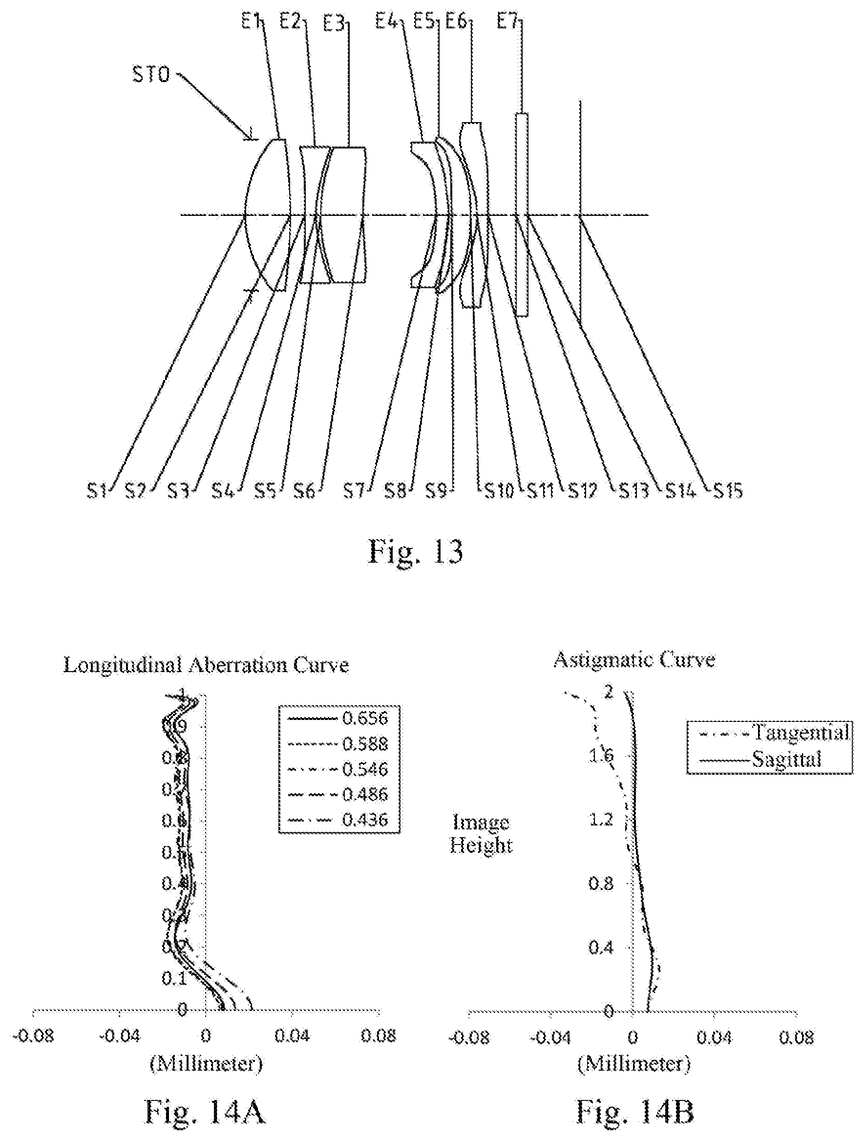
[0103] An optical imaging lens assembly according to embodiment 7 of the present disclosure is described below with reference to FIG. 13 to FIG. 14D. FIG. 13 is a schematic structural view of the optical imaging lens assembly according to embodiment 7 of the present disclosure.
[0104] As shown in FIG. 13, the optical imaging lens assembly according to an exemplary implementation includes, sequentially from an object side to an image side along an optical axis: a stop STO, a first lens E1, a second lens E2, a third lens E3, a fourth lens E4, a fifth lens E5, a sixth lens E6, an optical filter E7 and an imaging plane S15.
[0105] The first lens E1 has a positive refractive power, an object-side surface S1 thereof is a convex surface, and an image-side surface S2 thereof is a convex surface. The second lens E2 has a negative refractive power, an object-side surface S3 thereof is a concave surface, and an image-side surface S4 thereof is a concave surface. The third lens E3 has a positive refractive power, an object-side surface S5 thereof is a convex surface, and an image-side surface S6 thereof is a concave surface. The fourth lens E4 has a positive refractive power, an object-side surface S7 thereof is a concave surface, and an image-side surface S8 thereof is a convex surface. The fifth lens E5 has a positive refractive power, an object-side surface S9 thereof is a concave surface, and an image-side surface S10 thereof is a convex surface. The sixth lens E6 has a negative refractive power, an object-side surface S11 thereof is a concave surface, and an image-side surface S12 thereof is a concave surface. The optical filter E7 has an object-side surface S13 and an image-side surface S14. Light from the object sequentially passes through the respective surfaces S1 to S14 and is finally imaged on the imaging plane S15.
[0106] Table 19 shows surface type, radius of curvature, thickness, material and conic coefficient of each lens of the optical imaging lens assembly in embodiment 7, wherein the units for the radius of curvature and the thickness are millimeter (mm). Table 20 shows high-order coefficients applicable to each aspheric surface in embodiment 7, wherein the surface type of each aspheric surface may be defined by the formula (1) given above in embodiment 1. Table 21 shows effective focal lengths f1 to f6 of lenses, the total effective focal length f, a total optical length TTL, and half of a maximal field-of-view angle HFOV of the optical imaging lens assembly in embodiment 7.
TABLE-US-00019 TABLE 19 Sur- Material face Re- Abbe Conic num- Surface Radius of Thick- fractive num- coeffi- ber type curvature ness index ber cient OBJ spherical infinite infinite STO spherical infinite -0.1000 S1 aspheric 2.0903 0.8051 1.53 56.0 0.4918 S2 aspheric -7.3319 0.2601 -76.7750 S3 aspheric -1144.6615 0.2000 1.61 26.6 -99.0000 S4 aspheric 2.1186 0.0845 -4.5001 S5 aspheric 2.9131 0.7584 1.53 56.0 -2.1775 S6 aspheric 5.5995 1.3054 -55.1671 S7 aspheric -3.3793 0.2274 1.53 56.0 6.6958 S8 aspheric -1.5420 0.0500 -16.8144 S9 aspheric -5.5238 0.3431 1.61 26.6 16.0259 S10 aspheric -4.7759 0.1097 -88.9138 S11 aspheric -1.9117 0.2000 1.53 56.0 -6.7510 S12 aspheric 70.5480 0.4993 99.0000 S13 spherical infinite 0.2100 1.52 64.2 S14 spherical infinite 0.9471 S15 spherical infinite
TABLE-US-00020 TABLE 20 Surface number A4 A6 A8 A10 A12 A14 A16 A18 A20 S1 -1.1674E-03 -5.1337E-02 1.8088E-01 -3.8076E-01 4.9266E-01 -3.9992E-01 1.9858E-01 -5.5079E-02 6.5219E-03 S2 -1.1072E-02 5.7466E-02 -1.7319E-01 2.7329E-01 -2.5576E-01 1.4809E-01 -5.0768E-02 8.6420E-03 -3.9431E-04 S3 -9.8576E-02 5.3124E-01 -2.1092E+00 4.5149E+00 -5.8731E+00 4.8517E+00 -2.5088E+00 7.4405E-01 -9.6638E-02 S4 -1.4637E-01 1.2251E+00 -4.3874E+00 8.5402E+00 -1.0081E+01 7.5945E+00 -3.7040E+00 1.1097E+00 -1.5810E-01 SS -1.0722E-01 7.5272E-01 -2.1517E+00 3.1222E+00 -2.2496E+00 5.0607E-01 2.6054E-01 -1.4960E-01 1.6012E-02 S6 -1.4791E-02 7.1389E-04 2.4393E-02 -2.0195E-01 4.9662E-01 -6.4860E-01 4.7641E-01 -1.8604E-01 2.9993E-02 S7 1.2893E-01 -5.2903E-01 1.5612E+00 -5.1936E+00 1.2369E+01 -1.8603E+01 1.6288E+01 -7.5398E+00 1.4267E+00 S8 3.8108E-01 -6.6922E-01 -1.5632E+00 8.1157E+00 -1.4603E+01 1.4023E+01 -7.6095E+00 2.2069E+00 -2.6706E-01 S9 4.9741E-01 -1.0009E+00 -1.5428E-01 3.5366E+00 -6.4223E+00 5.8538E+00 -2.9860E+00 8.0639E-01 -8.9253E-02 S10 -5.4005E-01 1.8928E+00 -4.2329E+00 5.9661E+00 -5.6951E+00 3.6839E+00 -1.5253E+00 3.5803E-01 -3.5638E-02 S11 -5.2596E-01 2.0029E+00 -3.7023E+00 4.1142E+00 -2.9723E+00 1.4219E+00 -4.3413E-01 7.6278E-02 -5.8465E-03 S12 -1.4191E-01 4.9128E-01 -1.0109E+00 1.2400E+00 -9.7473E-01 4.9250E-01 -1.5417E-01 2.7244E-02 -2.0814E-03
TABLE-US-00021 TABLE 21 f1 (mm) 3.14 f2 (mm) -3.45 f3 (mm) 10.36 f4 (mm) 5.09 f5 (mm) 49.03 f6 (mm) -3.48 f (mm) 6.08 TTL (mm) 6.00 HFOV (.degree.) 17.5
[0107] FIG. 14A illustrates a longitudinal aberration curve of the optical imaging lens assembly according to embodiment 7, representing deviations of focal points converged by light of different wavelengths after passing through the optical imaging lens assembly. FIG. 14B illustrates an astigmatic curve of the optical imaging lens assembly according to embodiment 7, representing a curvature of a tangential plane and a curvature of a sagittal plane. FIG. 14C illustrates a distortion curve of the optical imaging lens assembly according to embodiment 7, representing amounts of distortion at different image heights. FIG. 14D illustrates a lateral color curve of the optical imaging lens assembly according to embodiment 7, representing deviations of different image heights on an imaging plane after light passes through the optical imaging lens assembly. It can be seen from FIG. 14A to FIG. 14D that the optical imaging lens assembly provided in embodiment 7 can achieve good image quality.
Embodiment 8
[0108] An optical imaging lens assembly according to embodiment 8 of the present disclosure is described below with reference to FIG. 15 to FIG. 16D. FIG. 15 is a schematic structural view of the optical imaging lens assembly according to embodiment 8 of the present disclosure.
[0109] As shown in FIG. 15, the optical imaging lens assembly according to an exemplary implementation includes, sequentially from an object side to an image side along an optical axis: a stop STO, a first lens E1, a second lens E2, a third lens E3, a fourth lens E4, a fifth lens E5, a sixth lens E6, an optical filter E7 and an imaging plane S15.
[0110] The first lens E1 has a positive refractive power, an object-side surface S1 thereof is a convex surface, and an image-side surface S2 thereof is a concave surface. The second lens E2 has a negative refractive power, an object-side surface S3 thereof is a convex surface, and an image-side surface S4 thereof is a concave surface. The third lens E3 has a positive refractive power, an object-side surface S5 thereof is a convex surface, and an image-side surface S6 thereof is a concave surface. The fourth lens E4 has a positive refractive power, an object-side surface S7 thereof is a concave surface, and an image-side surface S8 thereof is a convex surface. The fifth lens E5 has a negative refractive power, an object-side surface S9 thereof is a concave surface, and an image-side surface S10 thereof is a concave surface. The sixth lens E6 has a negative refractive power, an object-side surface S11 thereof is a concave surface, and an image-side surface S12 thereof is a convex surface. The optical filter E7 has an object-side surface S13 and an image-side surface S14. Light from the object sequentially passes through the respective surfaces S1 to S14 and is finally imaged on the imaging plane S15.
[0111] Table 22 shows surface type, radius of curvature, thickness, material and conic coefficient of each lens of the optical imaging lens assembly in embodiment 8, wherein the units for the radius of curvature and the thickness are millimeter (mm). Table 23 shows high-order coefficients applicable to each aspheric surface in embodiment 8, wherein the surface type of each aspheric surface may be defined by the formula (1) given above in embodiment 1. Table 24 shows effective focal lengths f1 to f6 of lenses, the total effective focal length f, a total optical length TTL, and half of a maximal field-of-view angle HFOV of the optical imaging lens assembly in embodiment 8.
TABLE-US-00022 TABLE 22 Sur- Conic face Material num- Surface Radius of Thick- Refractive Abbe coeffi- ber type curvature ness index number cient OBJ spherical infinite infinite STO spherical infinite -0.1000 S1 aspheric 2.1009 0.6982 1.53 56.0 0.4739 S2 aspheric 229.8968 0.2152 -99.0000 S3 aspheric 2.6039 0.2000 1.61 26.6 -19.4454 S4 aspheric 1.2572 0.1340 -4.0008 S5 aspheric 2.1977 0.7938 1.53 56.0 -2.3087 S6 aspheric 4.9777 1.3011 -53.7786 S7 aspheric -3.1604 0.2281 1.53 56.0 5.8710 S8 aspheric -1.4922 0.0500 -15.3674 S9 aspheric -5.0556 0.4050 1.61 26.6 14.3807 S10 aspheric 87.5545 0.1613 -99.0000 S11 aspheric -2.5182 0.2000 1.53 56.0 -4.3542 S12 aspheric -13.5908 0.4777 -99.0000 S13 spherical infinite 0.2100 1.52 64.2 S14 spherical infinite 0.9256 S15 spherical infinite
TABLE-US-00023 TABLE 23 Surface number A4 A6 A8 A10 A12 A14 A16 A18 A20 S1 -1.0880E-03 -5.0415E-02 1.5179E-01 -2.7399E-01 2.9716E-01 -1.9702E-01 7.7966E-02 -1.6903E-02 1.5458E-03 S2 -8.6087E-03 2.3644E-02 -1.8554E-02 -7.1157E-02 1.8757E-01 -1.9763E-01 1.0846E-01 -3.0584E-02 3.5105E-03 S3 -8.9603E-02 2.4470E-01 -7.0554E-01 1.1578E+00 -1.1275E+00 6.4869E-01 -2.0714E-01 3.0582E-02 -1.0203E-03 S4 -7.8660E-02 5.6680E-01 -1.9076E+00 3.7283E+00 -4.5748E+00 3.5772E+00 -1.7373E+00 4.8054E-01 -5.8171E-02 S5 -3.8270E-02 2.3867E-01 -7.0647E-01 1.1953E+00 -1.2488E+00 8.1683E-01 -3.2399E-01 7.0937E-02 -6.5595E-03 S6 5.3261E-03 -3.1448E-02 -4.7344E-02 1.6207E-01 -2.4763E-01 2.3333E-01 -1.3566E-01 4.3401E-02 -5.7373E-03 S7 1.2873E-01 3.3551E-02 -1.3183E+00 3.5326E+00 -6.2833E+00 7.1735E+00 -4.9138E+00 1.8436E+00 -2.9086E-01 S8 3.1946E-01 -5.4536E-01 6.2154E-01 -1.4441E+00 1.9908E+00 -1.1748E+00 1.3341E-01 1.3688E-01 -4.2033E-02 S9 4.4052E-01 -1.4795E+00 3.7274E+00 -7.2070E+00 8.9857E+00 -6.8366E+00 3.0554E+00 -7.3517E-01 7.3340E-02 S10 -2.8422E-01 2.8270E-01 -5.2358E-03 -6.1990E-01 9.5101E-01 -6.9533E-01 2.7895E-01 -5.9426E-02 5.3211E-03 S11 -2.6324E-01 3.0626E-01 2.7772E-01 -9.9551E-01 1.0831E+00 -6.2162E-01 2.0207E-01 -3.5280E-02 2.5796E-03 S12 -1.5201E-01 2.2908E-01 -1.3993E-01 5.4693E-03 3.8426E-02 -2.1096E-02 5.1117E-03 -6.0564E-04 2.8574E-05
TABLE-US-00024 TABLE 24 f1 (mm) 3.97 f2 (mm) -4.20 f3 (mm) 6.70 f4 (mm) 5.05 f5 (mm) -7.79 f6 (mm) -5.83 f (mm) 6.18 TTL (mm) 6.00 HFOV (.degree.) 18.5
[0112] FIG. 16A illustrates a longitudinal aberration curve of the optical imaging lens assembly according to embodiment 8, representing deviations of focal points converged by light of different wavelengths after passing through the optical imaging lens assembly. FIG. 16B illustrates an astigmatic curve of the optical imaging lens assembly according to embodiment 8, representing a curvature of a tangential plane and a curvature of a sagittal plane. FIG. 16C illustrates a distortion curve of the optical imaging lens assembly according to embodiment 8, representing amounts of distortion at different image heights. FIG. 16D illustrates a lateral color curve of the optical imaging lens assembly according to embodiment 8, representing deviations of different image heights on an imaging plane after light passes through the optical imaging lens assembly. It can be seen from FIG. 16A to FIG. 16D that the optical imaging lens assembly provided in embodiment 8 can achieve good image quality.
Embodiment 9
[0113] An optical imaging lens assembly according to embodiment 9 of the present disclosure is described below with reference to FIG. 17 to FIG. 18D. FIG. 17 is a schematic structural view of the optical imaging lens assembly according to embodiment 9 of the present disclosure.
[0114] As shown in FIG. 17, the optical imaging lens assembly according to an exemplary implementation includes, sequentially from an object side to an image side along an optical axis: a stop STO, a first lens E1, a second lens E2, a third lens E3, a fourth lens E4, a fifth lens E5, a sixth lens E6, an optical filter E7 and an imaging plane S15.
[0115] The first lens E1 has a positive refractive power, an object-side surface S1 thereof is a convex surface, and an image-side surface S2 thereof is a convex surface. The second lens E2 has a negative refractive power, an object-side surface S3 thereof is a convex surface, and an image-side surface S4 thereof is a concave surface. The third lens E3 has a positive refractive power, an object-side surface S5 thereof is a convex surface, and an image-side surface S6 thereof is a concave surface. The fourth lens E4 has a negative refractive power, an object-side surface S7 thereof is a concave surface, and an image-side surface S8 thereof is a convex surface. The fifth lens E5 has a positive refractive power, an object-side surface S9 thereof is a convex surface, and an image-side surface S10 thereof is a concave surface. The sixth lens E6 has a negative refractive power, an object-side surface S11 thereof is a concave surface, and an image-side surface S12 thereof is a concave surface. The optical filter E7 has an object-side surface S13 and an image-side surface S14. Light from the object sequentially passes through the respective surfaces S1 to S14 and is finally imaged on the imaging plane S15.
[0116] Table 25 shows surface type, radius of curvature, thickness, material and conic coefficient of each lens of the optical imaging lens assembly in embodiment 9, wherein the units for the radius of curvature and the thickness are millimeter (mm). Table 26 shows high-order coefficients applicable to each aspheric surface in embodiment 9, wherein the surface type of each aspheric surface may be defined by the formula (1) given above in embodiment 1. Table 27 shows effective focal lengths f1 to f6 of lenses, the total effective focal length f, a total optical length TTL, and half of a maximal field-of-view angle HFOV of the optical imaging lens assembly in embodiment 9.
TABLE-US-00025 TABLE 25 Material Conic Surface Surface Radius of Thick- Refractive Abbe coeffi- number type curvature ness index number cient OBJ spherical infinite infinite STO spherical infinite -0.1000 S1 aspheric 2.1197 0.6912 1.53 56.0 0.4536 S2 aspheric -107.9792 0.2047 99.0000 S3 aspheric 3.8319 0.2000 1.61 26.6 -19.2386 S4 aspheric 1.4262 0.1316 -3.7801 S5 aspheric 2.0333 0.8000 1.53 56.0 -2.3934 S6 aspheric 5.5172 1.3463 -38.9115 S7 aspheric -5.3432 0.2000 1.53 56.0 6.6275 S8 aspheric -1000.0000 0.2503 99.0000 S9 aspheric 3.4027 0.4481 1.61 26.6 -70.7158 S10 aspheric 7.4807 0.1126 -99.0000 S11 aspheric -6.5695 0.2000 1.53 56.0 0.5562 S12 aspheric 13.7096 0.3787 -92.1219 S13 spherical infinite 0.2100 1.52 64.2 S14 spherical infinite 0.8266 S15 spherical infinite
TABLE-US-00026 TABLE 26 Surface number A4 A6 A8 A10 A12 A14 A16 A18 A20 S1 -6.2740E-03 -2.9049E-02 1.0051E-01 -2.2100E-01 2.9702E-01 -2.5047E-01 1.2889E-01 -3.6942E-02 4.5238E-03 S2 -2.4153E-03 2.9590E-02 -1.0640E-01 1.6338E-01 -1.4482E-01 7.4027E-02 -1.6751E-02 -1.0751E-03 8.7701E-04 S3 -1.0259E-01 3.1608E-01 -9.5870E-01 1.8054E+00 -2.2376E+00 1.8494E+00 -9.7491E-01 2.9385E-01 -3.8265E-02 S4 -6.5833E-02 5.3611E-01 -1.9478E+00 4.3724E+00 -6.6585E+00 6.7852E+00 -4.3585E+00 1.5796E+00 -2.4483E-01 S5 -3.2808E-02 2.6236E-01 -9.6395E-01 2.3237E+00 -3.8880E+00 4.2661E+00 -2.8733E+00 1.0715E+00 -1.6887E-01 S6 -7.9845E-03 6.0826E-03 -1.1227E-01 3.5552E-01 -6.9251E-01 8.3408E-01 -6.0234E-01 2.3982E-01 -4.0459E-02 S7 3.6756E-02 -2.2912E-01 4.3409E-01 -9.1446E-01 1.2821E+00 -1.3079E+00 8.5225E-01 -2.8285E-01 3.2211E-02 S8 5.2419E-02 -2.2188E-01 5.4607E-01 -9.6446E-01 1.1400E+00 -9.6093E-01 5.4351E-01 -1.7464E-01 2.3303E-02 S9 9.9372E-02 -6.8507E-01 1.6339E+00 -3.0088E+00 3.7197E+00 -2.8442E+00 1.2524E+00 -2.8211E-01 2.3845E-02 S10 -1.9546E-01 1.1651E-02 1.8003E-01 -3.3942E-01 3.7407E-01 -2.6609E-01 1.1171E-01 -2.4543E-02 2.1622E-03 S11 -4.1249E-01 8.5005E-01 -7.6322E-01 4.0191E-01 -1.4829E-01 4.4046E-02 -1.0191E-02 1.4959E-03 -9.7780E-05 S12 -2.8656E-01 6.4718E-01 -7.0668E-01 4.5574E-01 -1.8518E-01 4.6294E-02 -6.4961E-03 4.1128E-04 -4.7988E-06
TABLE-US-00027 TABLE 27 f1 (mm) 3.90 f2 (mm) -3.83 f3 (mm) 5.58 f4 (mm) -10.06 f5 (mm) 9.78 f6 (mm) -8.29 f (mm) 6.08 TTL (mm) 6.00 HFOV (.degree.) 18.9
[0117] FIG. 18A illustrates a longitudinal aberration curve of the optical imaging lens assembly according to embodiment 9, representing deviations of focal points converged by light of different wavelengths after passing through the optical imaging lens assembly. FIG. 18B illustrates an astigmatic curve of the optical imaging lens assembly according to embodiment 9, representing a curvature of a tangential plane and a curvature of a sagittal plane. FIG. 18C illustrates a distortion curve of the optical imaging lens assembly according to embodiment 9, representing amounts of distortion at different image heights. FIG. 18D illustrates a lateral color curve of the optical imaging lens assembly according to embodiment 9, representing deviations of different image heights on an imaging plane after light passes through the optical imaging lens assembly. It can be seen from FIG. 18A to FIG. 18D that the optical imaging lens assembly provided in embodiment 9 can achieve good image quality.
[0118] In view of the above, embodiments 1 to 9 respectively satisfy the relationship shown in Table 28.
TABLE-US-00028 TABLE 28 Embodiment Formula 1 2 3 4 5 6 7 8 9 f*TAN(HFOV) 1.97 1.98 1.99 1.86 1.98 1.99 1.92 2.07 2.08 DT11/DT61 0.87 0.85 0.83 0.85 0.84 0.82 0.85 0.82 0.74 TTL/f 0.97 0.99 0.99 0.99 0.99 0.99 0.99 0.97 0.99 f1/f 0.64 0.65 0.65 0.56 0.65 0.65 0.52 0.64 0.64 |SAG41/T34| 0.35 0.36 0.35 0.33 0.36 0.35 0.34 0.28 0.35 (R5 + R11)/(R1 + R4) -0.10 -0.07 -0.74 -0.33 -0.39 -0.49 0.24 -0.10 -1.28 (1/f3 + 1/f6) .times. f2 0.11 0.07 -0.05 1.06 -0.06 -0.64 0.66 0.09 -0.22 (CT2 + CT4)/CT3 0.55 0.54 0.44 0.63 0.48 0.52 0.56 0.54 0.50 |f/R7-f/R8| 2.18 2.15 0.05 2.32 0.50 2.14 2.14 2.19 1.13 |f123/f456| 0.54 0.49 0.50 0.19 0.49 0.45 0.38 0.54 0.61 CT1/ 0.88 0.86 0.92 1.27 0.90 0.94 1.15 0.86 0.68 (T45 + CT5 + T56 + CT6) f1/.SIGMA.CT 1.56 1.55 1.57 1.37 1.57 1.47 1.24 1.57 1.54 (T23 + T45)/T34 0.14 0.14 0.20 0.22 0.19 0.16 0.10 0.14 0.28 f/f1/TAN(HFOV) 4.92 4.72 4.69 5.80 4.71 4.69 6.14 4.66 4.55
[0119] The present disclosure further provides an imaging apparatus, having an electronic photosensitive element which may be a photosensitive charge-coupled device (CCD) or complementary metal-oxide semiconductor (CMOS). The imaging apparatus may be an independent imaging device such as a digital camera, or may be an imaging module integrated in a mobile electronic device such as a mobile phone. The imaging apparatus is equipped with the optical imaging lens assembly described above.
[0120] The foregoing is only a description of the preferred embodiments of the present disclosure and the applied technical principles. It should be appreciated by those skilled in the art that the inventive scope of the present disclosure is not limited to the technical solutions formed by the particular combinations of the above technical features. The inventive scope should also cover other technical solutions formed by any combinations of the above technical features or equivalent features thereof without departing from the concept of the invention, such as, technical solutions formed by replacing the features as disclosed in the present disclosure with (but not limited to), technical features with similar functions.
* * * * *
D00000
D00001
D00002
D00003
D00004
D00005
D00006
D00007
D00008
D00009
D00010
D00011
D00012

D00013

D00014
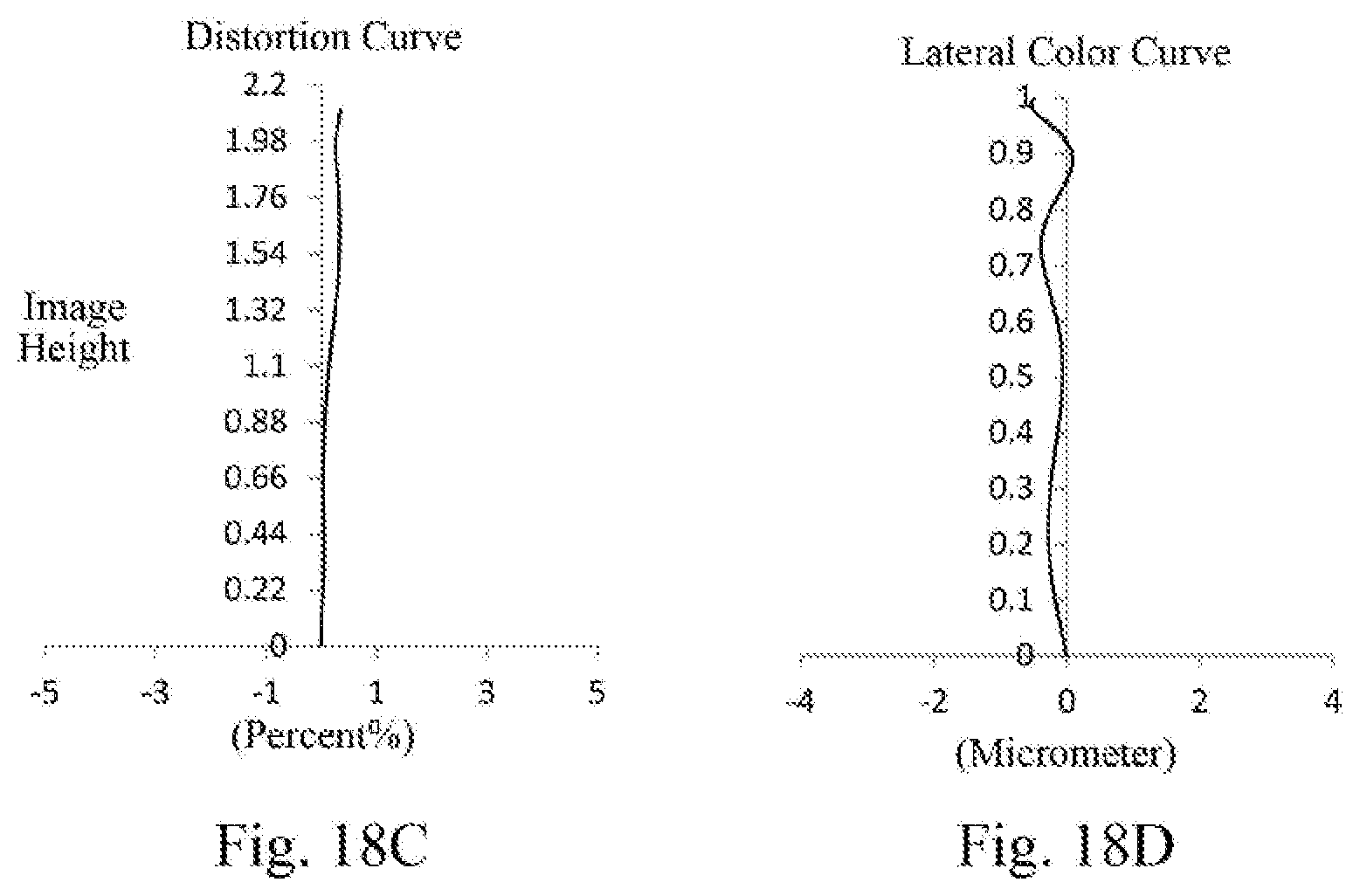

XML
uspto.report is an independent third-party trademark research tool that is not affiliated, endorsed, or sponsored by the United States Patent and Trademark Office (USPTO) or any other governmental organization. The information provided by uspto.report is based on publicly available data at the time of writing and is intended for informational purposes only.
While we strive to provide accurate and up-to-date information, we do not guarantee the accuracy, completeness, reliability, or suitability of the information displayed on this site. The use of this site is at your own risk. Any reliance you place on such information is therefore strictly at your own risk.
All official trademark data, including owner information, should be verified by visiting the official USPTO website at www.uspto.gov. This site is not intended to replace professional legal advice and should not be used as a substitute for consulting with a legal professional who is knowledgeable about trademark law.