Device Detecting Abnormality Of Secondary Battery, Abnormality Detection Method, And Program
TAKAHASHI; Kei ; et al.
U.S. patent application number 16/960375 was filed with the patent office on 2020-11-12 for device detecting abnormality of secondary battery, abnormality detection method, and program. The applicant listed for this patent is SEMICONDUCTOR ENERGY LABORATORY CO., LTD.. Invention is credited to Kei TAKAHASHI, Kouhei TOYOTAKA.
| Application Number | 20200355749 16/960375 |
| Document ID | / |
| Family ID | 1000005020191 |
| Filed Date | 2020-11-12 |


View All Diagrams
| United States Patent Application | 20200355749 |
| Kind Code | A1 |
| TAKAHASHI; Kei ; et al. | November 12, 2020 |
DEVICE DETECTING ABNORMALITY OF SECONDARY BATTERY, ABNORMALITY DETECTION METHOD, AND PROGRAM
Abstract
A secondary battery control system that conducts abnormality detection while predicting other parameters (internal resistance, SOC, and the like) with high accuracy is provided. A difference between an observation value (voltage) at a certain point in time and a voltage that is estimated using a prior-state variable is sensed. A threshold voltage is set in advance, and from the voltage difference that is sensed, a sudden abnormality, specifically a micro-short circuit or the like is detected. Furthermore, it is preferable that detection be performed by using a neural network to learn data on voltage difference in a time series and determine abnormality or normality.
| Inventors: | TAKAHASHI; Kei; (Isehara, Kanagawa, JP) ; TOYOTAKA; Kouhei; (Atsugi, Kanagawa, JP) | ||||||||||
| Applicant: |
|
||||||||||
|---|---|---|---|---|---|---|---|---|---|---|---|
| Family ID: | 1000005020191 | ||||||||||
| Appl. No.: | 16/960375 | ||||||||||
| Filed: | December 25, 2018 | ||||||||||
| PCT Filed: | December 25, 2018 | ||||||||||
| PCT NO: | PCT/IB2018/060597 | ||||||||||
| 371 Date: | July 7, 2020 |
| Current U.S. Class: | 1/1 |
| Current CPC Class: | G01R 31/367 20190101; H01M 10/0525 20130101; G01R 31/3842 20190101; H01M 10/48 20130101; G01R 19/16576 20130101 |
| International Class: | G01R 31/3842 20060101 G01R031/3842; H01M 10/0525 20060101 H01M010/0525; G01R 31/367 20060101 G01R031/367; G01R 19/165 20060101 G01R019/165 |
Foreign Application Data
| Date | Code | Application Number |
|---|---|---|
| Jan 11, 2018 | JP | 2018-002680 |
| Feb 2, 2018 | JP | 2018-017091 |
Claims
1. An abnormality detection device of a secondary battery comprising: a first sensing circuit configured to sense a voltage value of the secondary battery to be a first observation value; a second sensing means sensing circuit configured to sense a current value of the secondary battery to be a second observation value; a calculation unit calculating an estimated voltage value range using a regression model, and a determination unit finding a difference between the voltage value of the first observation value and the estimated voltage value obtained from a previous time and determining the secondary battery has an abnormality when the difference exceeds a certain threshold value range.
2. The abnormality detection device of a secondary battery according to claim 1, wherein the regression model is a Kalman filter on the basis of a state equation.
3. The abnormality detection device of a secondary battery according to claim 1, wherein the determination unit comprises one or a plurality of comparators.
4. The abnormality detection device of a secondary battery according to claim 1, further comprising a neural network structure portion inputting the difference between the voltage value of the first observation value and the estimated voltage value obtained from a previous time.
5. The abnormality detection device of a secondary battery according to claim 1, wherein the secondary battery is a lithium-ion secondary battery.
6. The abnormality detection device of a secondary battery according to of claim 1, wherein the secondary battery is an all-solid-state battery.
7. An abnormality detection method determining whether a secondary battery has an abnormality, comprising: a prior-estimation prediction step outputting an estimated voltage value using a regression model, and a filtering step calculating a post-state estimation value and a post error covariance matrix.
8. The abnormality detection method according to claim 7, wherein the regression model is a Kalman filter on the basis of a state equation.
9. A non-transitory computer readable medium storing a program, the program being for making a computer which comprises: a calculation unit calculating an estimated voltage value using a regression model, and a determination unit finding a difference between a voltage value of the observation value and the estimated voltage value obtained from a previous time determining a secondary battery has an abnormality when the difference exceeds a certain threshold value range.
10. The non-transitory computer readable medium storing the program according to claim 9, wherein the regression model is a Kalman filter on the basis of a state equation.
11. A state estimation method of a secondary battery estimating a charging state of the secondary battery, wherein data on an observation value is obtained from the secondary battery, wherein a prior-state estimation value is calculated using a regression model, wherein a forecast error voltage Vd which is a difference between the observation value and the prior-state estimation value is calculated, wherein whether data is noise is determined on the basis of whether or not data of the forecast error voltage Vd exceeds a threshold value set in advance, wherein instead of data that is determined as noise, a mean value of k data before abnormality sensing is input to the regression model after which correction is performed, and wherein abnormality detection is continued even after noise sensing.
12. The state estimation method of a secondary battery according to claim 11, wherein the regression model is a Kalman filter on the basis of a state equation.
13. The state estimation method of a secondary battery according to claim 11, wherein noise is generated when a micro-short circuit of the secondary battery occurs.
14. A charging state estimation device of a secondary battery estimating a charging state of the secondary battery, comprising: a first sensing circuit configured to sense a voltage value of the secondary battery that is to be a first observation value, a calculation unit calculating an estimated voltage value using a regression model, and a determination unit finding a difference between the voltage value of the first observation value and the estimated voltage value obtained from a previous time and determining the secondary battery has an abnormality when the difference exceeds a certain threshold value range, wherein the determination unit comprises one or a plurality of comparators, a multiplexer, and a delay circuit.
15. The charging state estimation device of a secondary battery according to claim 14, wherein the regression model is a Kalman filter on the basis of a state equation.
16. The charging state estimation device of a secondary battery according to claim 14, wherein the determination unit comprises one or a plurality of comparators.
17. The charging state estimation device of a secondary battery according to claim 14, further comprising a second sensing circuit configured to sense a current value of the secondary battery to be a second observation value.
Description
TECHNICAL FIELD
[0001] One embodiment of the present invention relates to an object, a method, or a manufacturing method. Alternatively, the present invention relates to a process, a machine, manufacture, or a composition (a composition of matter). One embodiment of the present invention relates to a manufacturing method of a semiconductor device, a display device, a light-emitting device, a power storage device, a lighting device, or an electronic device. In addition, one embodiment of the present invention relates to a method of controlling charge of a power storage device, a method of estimating the state of a power storage device, and a method of detecting abnormality of a power storage device. In particular, one embodiment of the present invention relates to a charge system of a power storage device, a state estimation system of a power storage device, and an abnormality detection system of a power storage device.
[0002] Note that in this specification, a power storage device refers to every element and device having a function of storing power. For example, the power storage device includes a storage battery (also referred to as secondary battery) such as a lithium-ion secondary battery, a lithium-ion capacitor, a nickel hydrogen battery, an all-solid-state battery, and an electric double layer capacitor.
[0003] One embodiment of the present invention relates to an abnormality detection system of a power storage device and a state estimation device of a power storage device using a neural network. One embodiment of the present invention relates to vehicles using a neural network. One embodiment of the present invention relates to an electronic device using a neural network. One embodiment of the present invention is not limited to vehicles, and is related to a state estimation system and an abnormality detection system that can be applied to a power storage device for storing electric power obtained from power generation facilities such as a solar power generation panel provided in a structure body.
BACKGROUND ART
[0004] In recent years, a variety of power storage devices such as lithium-ion secondary batteries, lithium-ion capacitors, and air batteries have been actively developed. In particular, demand for lithium-ion secondary batteries with high energy density have rapidly grown with the development of the semiconductor industry for portable information terminals such as mobile phones, smartphones, tablets, or laptop computers; game machines; portable music players; digital cameras; medical equipment; next-generation clean energy vehicles such as hybrid electric vehicles (HEVs), electric vehicles (EVs), and plug-in hybrid electric vehicles (PHEVs); electric bikes; or the like, and lithium-ion secondary batteries have become essential as rechargeable energy supply sources for the modem information society.
[0005] Electric vehicles are vehicles in which only an electric motor is used for a driving portion, and there are also hybrid vehicles having both an internal-combustion engine such as an engine and an electric motor. A plurality of secondary batteries used in vehicles are provided as a battery pack, and a plurality of the battery packs are provided on the lower portion of a vehicle.
[0006] The secondary battery used in an electric vehicle, a hybrid electric vehicle or an electric bike degrades due to the number of charging, depth of discharge, charge current, charging environment (temperature change), or the like. The degradation also depends on the usage of the user; and charging temperatures, frequency of quick charging, charging amount from regenerative braking, charging timing with a regenerative brake, and the like might be related to the degradation. An abnormality such as a short circuit may occur in the secondary battery used in an electric vehicle or a hybrid electric vehicle due to degradation over time or the like.
[0007] Having a high reliability is desirable for the secondary battery used for an electric vehicle, a hybrid electric vehicle, or an electric bike because it is assumed to be used for a long time.
[0008] In the design capacity (DC) of a lithium-ion secondary battery, the proportion of the remaining capacity (RC) in the full charge capacity (FCC), that is, the state of charge (SOC), is not set to use all of the design capacity from 0% to 100%, and a margin of 5% (or 10%), not 0%, is provided to prevent overdischarge. In addition, to prevent overcharge, a margin of approximately 5% (or 10%), not 100%, is provided; accordingly, a design capacity within a range of 5% to 95% (or within a range of 10% to 90%) is said to be used. In practice, a design capacity of 5% to 95% (or within a range of 10% to 90%) is used by setting the voltage range of an upper limit voltage V.sub.max and a lower limit voltage V.sub.min using a BMS (Battery Management System) connected to a secondary battery.
[0009] Degradation in a secondary battery occurs due to usage, change over time, or change in temperature. The secondary battery is managed by accurately determining the state of the inside of the secondary battery, particularly the SOC (state of charge). By accurately determining the SOC, the voltage range of the upper limit voltage V.sub.max and the lower limit voltage V.sub.min can be widened. Conventionally, the SOC is estimated by a coulomb counting method.
[0010] Patent Document 1 shows an example where a neural network is used for calculation of the remaining capacity of a secondary battery.
REFERENCE
Patent Document
[0011] [Patent Document 1] United States Published Patent Application No. 2006/0181245
SUMMARY OF THE INVENTION
Problems to be Solved by the Invention
[0012] An object is to secure safety by sensing abnormality in a secondary battery, for example, sensing a phenomenon that lowers the safety of the secondary battery early and warning users or changing the operating conditions of the secondary battery.
[0013] In a conventional abnormality detection of a secondary battery, when the secondary battery degrades and errors occur, corrections are required; however, corrections by feedback are not made and are insufficient, hence the accuracy is low. An object is to increase the accuracy of abnormality detection of a secondary battery.
[0014] In the case where a large noise is generated in a secondary battery, when monitoring the internal resistance, SOC, and the like of the secondary battery, an error of the numerical value of the SOC to be estimated later occurs due to the noise data that is input. An object is to provide a control system of a secondary battery that ideally predicts other parameters (internal resistance, SOC, and the like) with high accuracy while performing abnormality detection.
Means For Solving the Problems
[0015] In a lithium-ion battery, only parameters of a current, a voltage, and a temperature can he measured, and it is difficult to measure the internal resistance and the SOC (state of charge) directly. Therefore, arithmetic processing using a regression model (regression method) such as a regression analysis, a Kalman filter, and a multiple regression analysis is performed to estimate the internal resistance and the SOC.
[0016] A Kalman filter is a kind of infinite impulse response filter. A multiple regression analysis is a multivariate analysis and uses a plurality of independent variables in a regression analysis. Examples of the multiple regression analysis include a least-squares method. The regression analysis requires a large number of observation values of time series, whereas the Kalman filter has an advantage of being able to obtain an optimal correction coefficient successively as long as there is an accumulation of data to some extent. Moreover, the Kalman filter can be applied to transient time series.
[0017] As a method of estimating the internal resistance and the SOC of the secondary battery, a non-linear Kalman filter (specifically an unscented Kalman filter (also referred to as UKF)) can be used. In addition, an extended Kalman filter (also referred to as EKF) can be used.
[0018] Estimating the internal resistance and the SOC of the secondary battery using a Kalman filter is known, and it is difficult to sense sudden abnormalities, specifically a micro-short circuit and the like, using only this method. When estimating the internal resistance and the SOC of the secondary battery, a post-state estimation value is treated as an output; however, in this invention, a state estimation value is not directly used, and sudden abnormalities can be sensed by using a difference between an observation value and a prior-state estimation value.
[0019] In order to achieve the above objects, in the abnormality detection device, the abnormality detection system, and the abnormality detection method of a secondary battery disclosed in this specification, the following means is used.
[0020] Using a Kalman filter, a difference between an observation value (voltage) at a certain point in time and a voltage that is estimated using a prior-state variable is sensed. A threshold voltage is set in advance, and a sudden abnormality, specifically a micro-short circuit, is sensed using the sensed voltage difference. An abnormality in a secondary battery can be detected early by sensing a micro-short circuit or the like.
[0021] A micro-short circuit refers to a minute short circuit in a secondary battery and a phenomenon in which a short circuit of a positive electrode and a negative electrode of the secondary battery does not make charging and discharging impossible, and a small amount of short-circuit current flows through a minute short circuit portion. A cause of a micro-short circuit is a plurality of charging and discharging; an uneven distribution of positive electrode active materials leads to local concentration of current in part of the positive electrode and the negative electrode; and then part of a separator stops functioning or a by-product is generated by a side reaction, which is thought to generate a micro short-circuit.
[0022] A thinner separator to make a secondary battery smaller and quick electric power supply at a high voltage are desired for an ideal secondary battery, both of which have configurations that allow a micro-short circuit to occur in a secondary battery easily. Moreover, repetition of micro-short circuits may cause abnormal heating in a secondary battery, and may lead to serious accidents such as a fire.
[0023] Thus, an abnormality detection system, a secondary battery control system, or a secondary battery charging system is configured for early sensing and preventing serious accidents from happening in the case where a micro-short circuit occurs. A micro-short circuit is an abnormality particular to a secondary battery, and thus far, a method or a system of paying attention to the micro-short circuit and sensing the micro-short circuit has not existed. The present inventors build a system that finds and calculates a value that changes greatly when a micro-short occurs. In addition, correction by feedback is provided using an AI (Artificial Intelligence) system (neural network) to perform sensing of an abnormality in a secondary battery.
[0024] A measurement model for performing sensing of an abnormality in a secondary battery is described below. Here, the model is a model of an abnormality detection system of a secondary battery, and output from the system is determined by calculation according to the steps for inputting to the system that have been established in advance or performing a simulation. A method (for example, a neural network, a hidden Markov model, a polynomial function approximation, or the like) for determining an optimal output with respect to an input of the system by means such as regression and learning is used as a model. These models are examples, and are not limited.
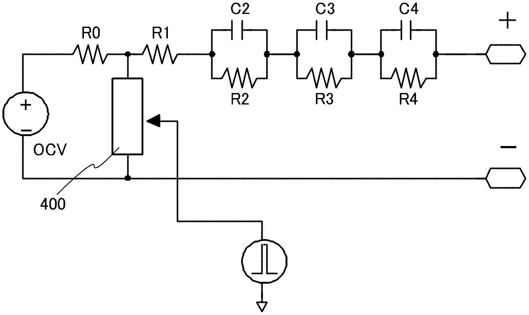
[0025] In a prior-estimate prediction step, a model and an input value are used, and in a post-estimate step (also referred to as a filtering step), an observation value is used.
x(k+1)=Ax(k)+bu(k)+bv(k) Equation 1
[0026] The above equation is a state e ration. that expresses the transition of the system.
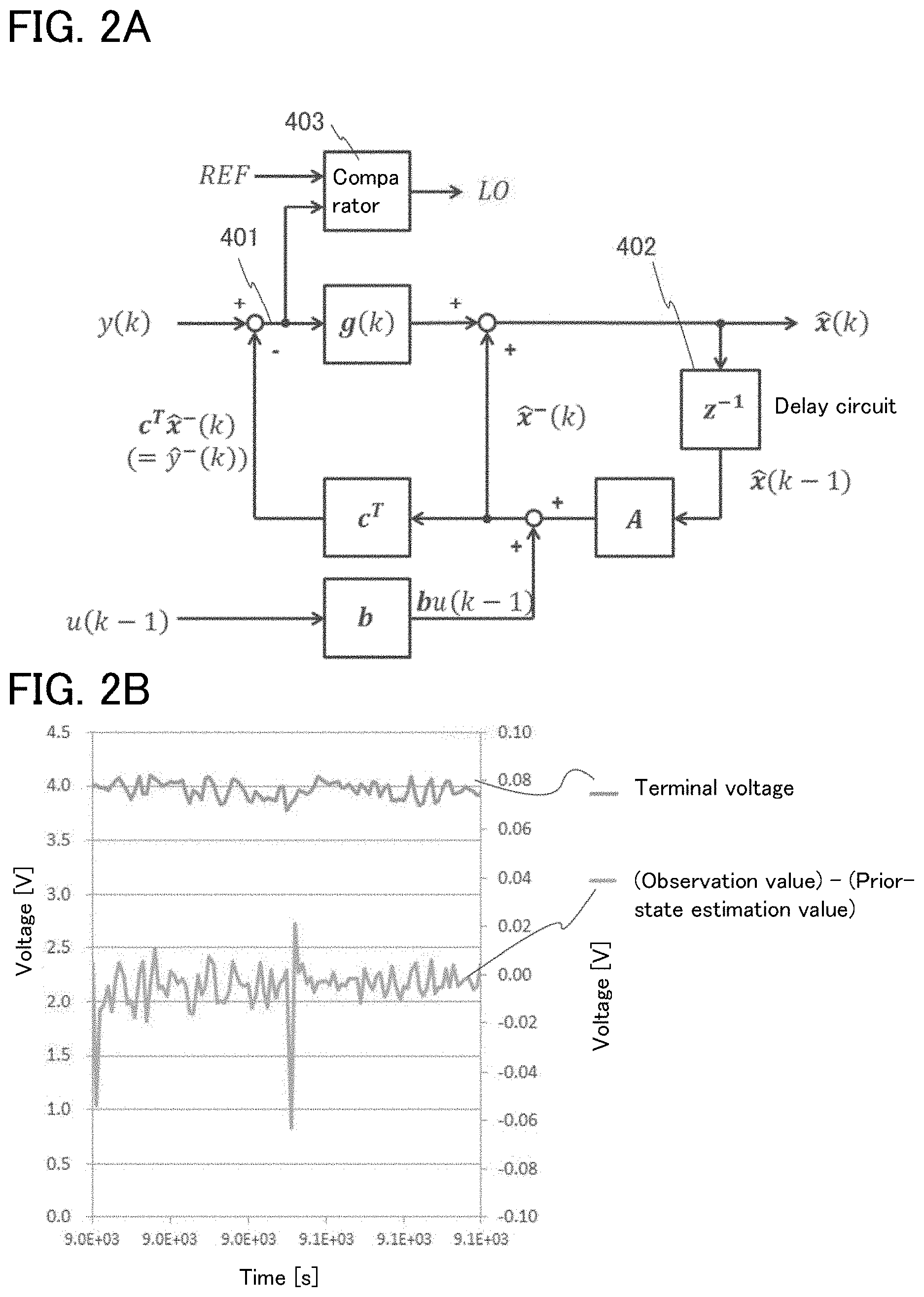
[0027] The relationship between an observation value y(k) and x(k) in a point in tune (time k) is represented by the following.
y(k)=c.sup.Tx(k)+w(k) Equation 2
[0028] c.sup.T is an observation model that has a function of linear mapping a state space into an observation space. w(k) represents an observation noise. The above equation is an observation equation.
[0029] The state equation and the observation equation are collectively called state space.
[0030] The prior-state estimation value (on the left) can be expressed by the following equation.
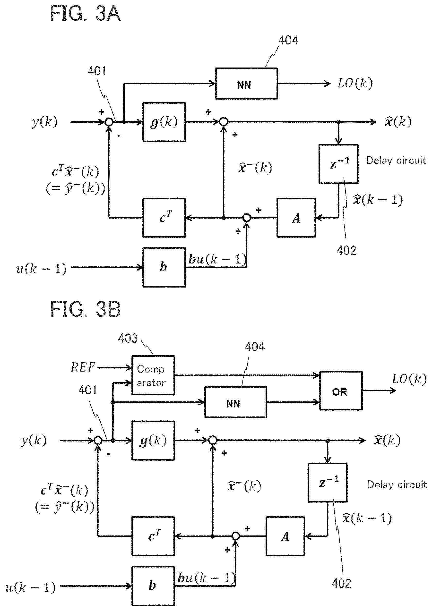
{circumflex over (x)}.sup.-(k)=A{circumflex over (x)}(k-1)+bu(k-1) Equation 3
[0031] Note that k is an integer of 0, 1, 2, or the like, and k represents time. u(k) is an input signal and is a combined current value in the case of a secondary battery, and x(k) expresses a state variable.
[0032] In addition, a prior error covariance (P.sup.-(k) on the left represents an inverse matrix of a covariance matrix) can be expressed by the following equation.
P.sup.-(k)=AP(k-1)A.sup.T+.sigma..sub..nu..sup.2bb.sup.T Equation 4
[0033] In the prior-estimate prediction step, the prior-state estimation value and a prior covariance matrix of a state are calculated in accordance with the state equation. A prior-state estimation value and a prior covariance matrix at time k+1 are calculated in accordance with a post-state estimation value and a post covariance matrix of a state at time k.
[0034] An estimation value and an actual measurement of the voltage (the observation value) are compared, and a Kalman gain which is a weight coefficient of a difference is calculated using a Kalman filter, after which the estimation value is corrected. The Kalman gain g(k) used in the filtering step can be expressed by the following equation.
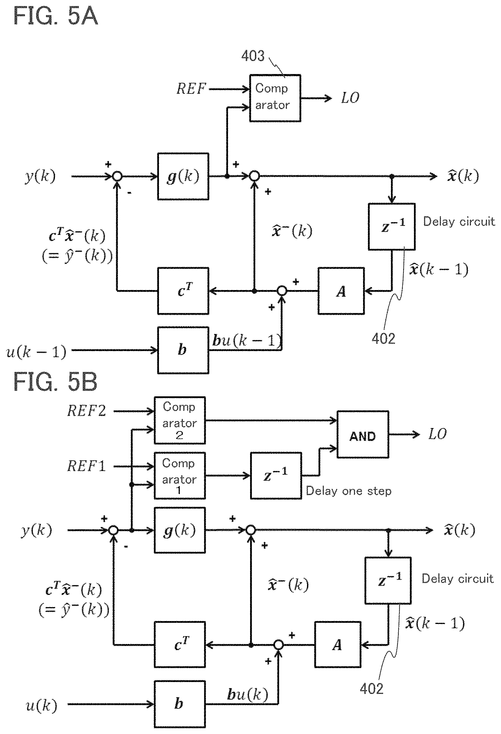
g ( k ) = P - ( k ) c c T P - ( k ) c + .sigma. .omega. 2 [ Equation 5 ] ##EQU00001##
[0035] A post-state estimation value (on the left) used in the filtering step can be expressed by the following equation.
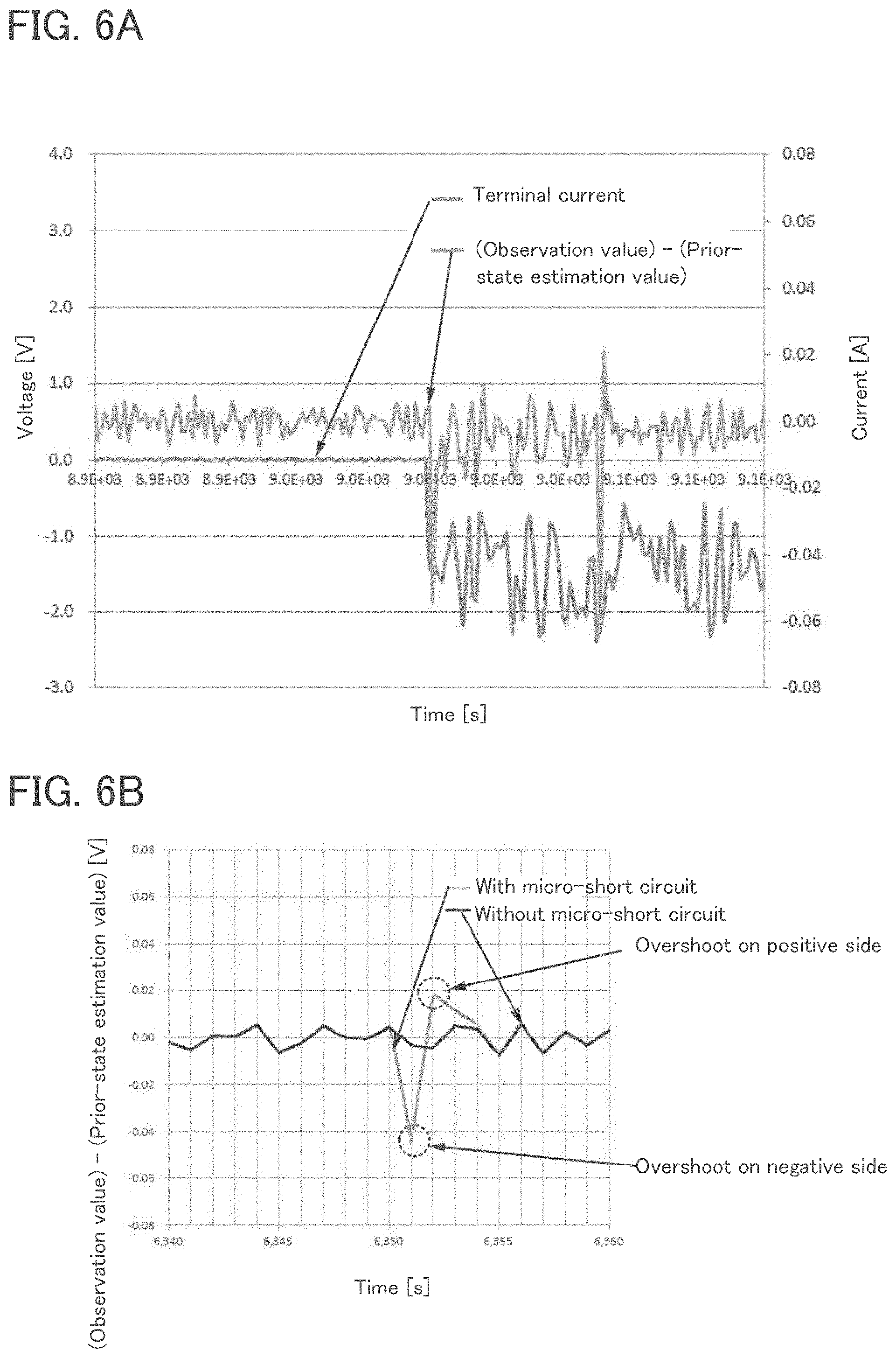
{circumflex over (x)}(k)={circumflex over (x)}.sup.-(k)+g(k)(y(k)-c.sup.T{circumflex over (x)}.sup.-(k)) Equation 6
[0036] A post error covariance matrix P(k) used in the filtering step can be expressed by the following equation.
P(k)=(I-g(k)c.sup.T)P.sup.-(k).sub..nu. Equation 7
[0037] With the above measurement model of sensing an abnormality that occur in a secondary battery, the value obtained from the equation below, that is, a difference (voltage difference) between an observation value (voltage) at a certain point in time and a voltage that is estimated using a prior-state variable is monitored, and abnormality is sensed by regarding a large change in behavior of the value as an occurrence of abnormality such as a micro-short circuit.
y(k)-c.sup.T{circumflex over (x)}.sup.-(k) Equation 8
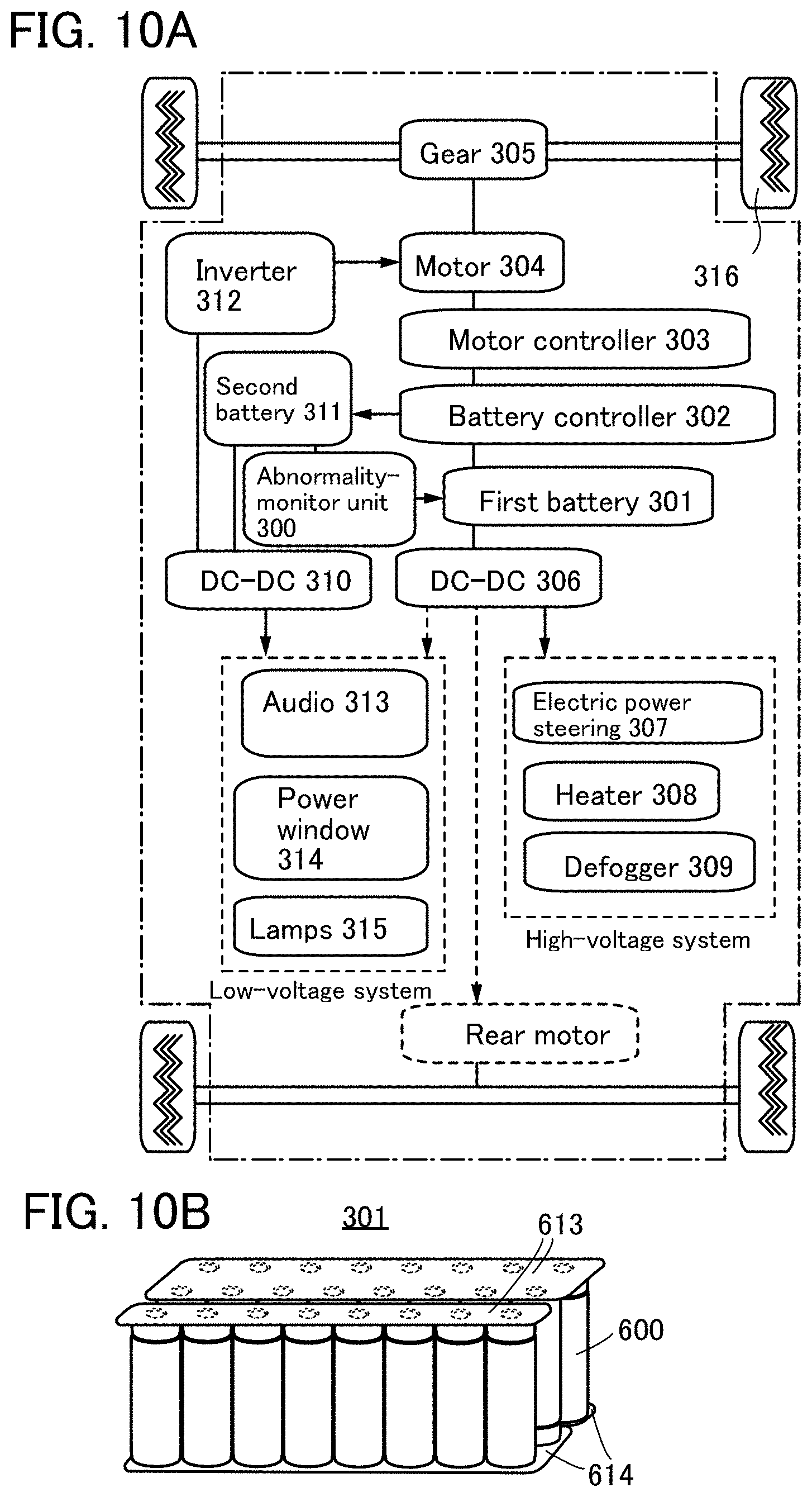
[0038] In the case where a comparator or the like outputs a signal when the value of voltage difference obtained from the equation above exceeds a certain threshold value and an abnormality is sensed, a signal for displaying that notifies the outside with an abnormality signal is output to a display or a signal for warning with a buzzer or the like is output to a speaker. In this specification, the terms "sensing" and "detection" are used separately. "Detection" refers to a case where an abnormality data is sensed, and when the abnormality data is correct, notification to the outside, that is, a signal is output to other circuits. "Sensing" is defined as only picking up abnormality data including noise (abnormality data that is incorrect). Therefore, "sensing" is part of but does not equate to "detection", and "detection" at least includes notifying (outputting a signal) to other circuits.
[0039] When a charging state is switched to a discharging state, or when a discharging state is switched to a charging state, the voltage difference changes greatly and noise is generated. The generation of this noise does not lead to an abnormality in a secondary battery, and thus a plurality of comparators can be provided to remove this noise.
[0040] A structure disclosed in this specification is an abnormality detection device including a first sensing means that senses a voltage value of a secondary battery that is to be a first observation value; a second sensing means that senses a current value of the secondary battery that is to be a second observation value; a calculation unit that calculates a prior-state estimation value (estimated voltage value) using a Kalman filter on the basis of a state equation; and a determination unit that finds a difference between the voltage value of the first observation value and the estimated voltage value obtained from a previous time and determines that the secondary battery has an abnormality (micro-short circuit) when the difference exceeds a certain threshold value range.
[0041] In the above structure, the determination unit includes one or a plurality of comparators. By using a plurality of comparators, noise can be removed and errors in abnormality sensing can be reduced.
[0042] It is preferable that detection be performed by learning data on voltage difference in a time series using a neural network and determining abnormality or normality. The above structure includes a neural network structure portion that inputs a difference between the voltage value of the first observation value and the estimated voltage value obtained from the previous time.
[0043] Another structure disclosed in this specification is an abnormality detection method determining whether a secondary battery has an abnormality, and includes a prior-estimate prediction step outputting an estimated voltage value using a Kalman filter on the basis of a state equation and a filtering step calculating a post-state estimation value and a post error covariance matrix.
[0044] Another structure disclosed in this specification is a program that makes a computer function as a calculation unit that calculates a prior-state estimation value (estimated voltage value) using a Kalman filter on the basis of a state equation and a determination unit that finds a difference between a voltage value of the observation value and the estimated voltage value obtained from a previous time and determines that the secondary battery has an abnormality when the difference exceeds a certain threshold value range.
[0045] An abnormality detection system of a secondary battery can be formed using the above abnormality detection device, the above method, and a computer that executes the above program. Examples of the computer includes a control device of an electric vehicle, a smartphone, and a laptop personal computer, and the computer includes a control unit, a memory unit, and an input/output unit. The control unit includes a CPU (or an MPU or an MCU (Micro Controller Unit)) or the like. The control unit can also use a GPU (Graphics Processing Unit). A chip in which a CPU and a GPU are integrated is sometimes called an APU (Accelerated Processing Unit), and this APU chip can also be used. An IC with an AI system (also referred to as an inference chip) can be used. The IC with an AI system is referred to as a circuit performing neural network calculation (a microprocessor) in some cases.
[0046] The memory unit includes a RAM, a ROM, an HDD, or the like. The input/output unit includes an operation portion, a display portion, a communication portion, and the like. The program is not limited to being stored in the memory unit of a computer, and may be stored in a storage medium that the computer can read and the computer reads and executes the program. Examples of a storage medium that the computer can read include a disc such as a CD-ROM, a magnetic tape, a USB memory, and a flash memory. Furthermore, the above program may be stored in a device that is connected to a connection line such as the Internet, a LAN (Local Area Network), or a wireless LAN, and the computer may read the program from the connection line and executes the program.
[0047] Another structure disclosed in this specification is an abnormality detection system that detects a micro-short circuit. The abnormality detection system includes a first sensing means that senses a voltage value of a secondary battery that is to be a first observation value; a second sensing means that senses a current value of the secondary battery that is to be a second observation value; a calculation unit that calculates a prior-state estimation value (estimated voltage value) using a Kalman filter on the basis of a state equation; and a determination unit that finds a difference between the voltage value of the first observation value and the estimated voltage value obtained from a previous time and determines that the secondary battery has an abnormality (micro-short circuit) when the difference exceeds a certain threshold value range. The abnormality detection system detects data derived from the micro-short circuit.
[0048] The abnormality detection system of a secondary battery disclosed in this specification always or periodically monitors the secondary battery. The sampling cycle (and the calculation cycle) can be set as appropriate. The abnormality detection system of a secondary battery disclosed in this specification can also be called a secondary battery monitoring system. Furthermore, when sensing of an abnormality in a secondary battery such as an external surface temperature or an external deformity using a temperature sensor, a camera, a gas sensor, or the like are included in the abnormality detection system for a secondary battery, an abnormality can be sensed more certainly.
[0049] A forecast error determined as an abnormality is not input to a Kalman filter and a forecast error determined as a normality is input instead. The accuracy of the estimation can be increased by calculating the internal resistance and the SOC of a secondary battery without using an abnormal value.
[0050] Another structure disclosed in this specification is a state estimation method of a secondary battery that estimates a charging state of a secondary battery. In the state estimation method of a secondary battery, data on an observation value is obtained from the secondary battery; a prior-state estimation value is calculated using a regression model; a forecast error voltage Vd which is a difference between the observation value and the prior-state estimation value is calculated; whether data is noise is determined on the basis of whether or not data of the forecast error voltage Vd exceeds a threshold value set in advance; instead of data that is determined as noise, a mean value of k data before abnormality sensing is input to the regression model after which correction is performed; and abnormality detection is continued even after noise sensing.
[0051] A micro-short circuit problem occurs during charging. For example, in the case where only one battery is employed, current is controlled by a charger; thus the perceived current value does not change during a micro-short circuit, and a change in voltage is observed. However, in the case of parallel batteries, the change in voltage becomes small and sensing becomes difficult. Moreover, this change in voltage is within the range of upper and lower limit voltages of battery use, and hence a special detecting mechanism is required. Furthermore, regarding current, in parallel batteries, the internal resistance decreases when a micro-short circuit occurs; hence the amount of current that flows into a healthy battery becomes relatively small and a large amount of current flows into an abnormal battery, which is dangerous. However, it is difficult to detect an abnormality because a controlled value of current is maintained in the whole battery pack. In the case of a structure of a typical battery pack, it is common to monitor the voltage of each set of series; however, monitoring the current of all the batteries is difficult in terms of costs and the complexity of the wirings.
[0052] As shown in the flow chart in FIG. 14, when a value is found to be small when compared with a signal REF using a comparator, that is, when the value obtained in Equation 8<REF, an abnormality such as a micro-short circuit is deemed to have occurred, and after sensing this abnormality, forecast error data is created; for example, the mean of normal forecast errors of previous one to four steps is put into the Kalman filter. The SOC can be accurately found even after detecting abnormality. An advantage of the Kalman filter is that the remaining capacity can be forecast with high accuracy, and even if the initial remaining capacity is unknown, the remaining capacity can be forecast.
[0053] Hitherto, there is a problem where an error in estimation value occurs before or after a micro-short circuit occurs, and it varies from the actual capacity value. The accuracy of the estimation results can be increased by removing data derived from the occurrence of a micro-short circuit and inputting a normal value.
[0054] Thus, data that is the basis of the abnormality detection is not used for prediction after the abnormality detection, whereby a secondary battery can be used until a micro-short circuit occurs again after the abnormality detection.
[0055] A prediction method for predicting the charging state of a secondary battery is described below. After abnormality sensing in a secondary battery is carried out, the steps for prediction continue to be repeatedly carried out. In the prediction, a method (for example, a neural network, a hidden Markov model, a polynomial function approximation, or the like) for determining an optimal output with respect to a system input by means such as regression and learning is used. To perform learning, it is preferable to use a large amount of data and analysis for learning; hence the learning may be conducted at a site such as a workstation or an appliance server, and in that case one or more servers are used and data accumulation and analysis are performed automatically or semi-automatically in coordination with an operator. In the case where storage and analysis of a large amount of data have finished and results have been obtained, by integrating the results into a system, specifically a program or a memory such as an IC chip, abnormality sensing and prediction of a charging state can be conducted without using a server.
[0056] In the case where power is wirelessly supplied to charge a secondary battery, the abnormality detection system of a secondary battery disclosed in this specification can be used. Methods for wirelessly transmitting power of several watts or more in a distance of several tens of centimeters or less include an electromagnetic induction method and a magnetic resonance method. The electromagnetic induction method includes a Qi (dice) standard. The magnetic resonance method includes a WiPower standard. Power from a power-transmitting device is received by a receiving coil, and an abnormality detection device is provided between the receiving coil and the secondary battery. In the case where the abnormality detection device detects an abnormality, instruction of stopping power from the power-transmitting device using a connection function wireless LAN or Blue tooth (registered trademark)) is performed.
[0057] An embodiment described below in this specification includes use of a dedicated computer or a general-purpose computer including a variety of kinds of computer hardware or software. A computer-readable recording medium can be used and mounted on the embodiment described below in this specification. The recording medium may include a RAM, a ROM, an optical disk, a magnetic disk, or any other storage media that can be accessed by a computer. Algorithms, components, flows, programs, and the like presented as examples in an embodiment described below in this specification can be implemented in software or implemented in a combination of hardware and software.
Effect of the Invention
[0058] By monitoring the value of the above Equation 8 (voltage difference), an easy and highly accurate abnormality sensing of a secondary battery is made possible. Furthermore, performing abnormality sensing of a secondary battery with input of correction by feedback using a neural network enables abnormality sensing of a secondary battery with a higher accuracy.
[0059] Moreover, not only abnormality detection of one secondary battery but also abnormality detection of a plurality of secondary batteries connected in series can be performed.
[0060] A secondary battery is not limited to a lithium-ion secondary battery using an electrolyte solution, and an all-solid-state battery using a solid electrolyte, a sodium-ion secondary battery, a potassium-ion secondary battery, and the like can be used. A potassium-ion secondary battery has a weak ability in attracting solvents compared with lithium or sodium, and ion can move freely in the electrolyte solution. When the kind or size of the secondary battery is changed, the threshold value is set as appropriate in accordance with the secondary battery. Since a micro-short circuit can also occur in an all solid-state battery, the abnormality detection system disclosed in this specification is useful.
[0061] The abnormality detection system disclosed in this specification is useful because it can be mounted on an IC chip or the like, and can be incorporated in part of a system of a vehicle. The abnormality detection system can be an IC chip in which other functional circuits (Random Access Memory (RAM), GPU (Graphics Processing Unit), PMU (Power Management Unit), and the like) are integrated.
[0062] The abnormality detection system disclosed in this specification can shorten the timing of sensing and can achieve abnormality sensing in real time. Furthermore, abnormality sensing can be achieved regardless of the state of the secondary battery such as charging or discharging.
[0063] Moreover, a secondary battery control system that detects an abnormality in a secondary battery in real time, removes noise used for abnormality detection, and predicts other parameters (internal resistance, SOC, and the like) with high accuracy can be achieved.
BRIEF DESCRIPTION OF THE DRAWINGS
[0064] FIG. 1 An equivalent circuit model illustrating one embodiment of the present invention.
[0065] FIG. 2 FIG. 2(A) is a functional block diagram illustrating one embodiment of the present invention, and FIG. 2(B) is a diagram illustrating the relationship between voltage difference and time.
[0066] FIG. 3 Functional block diagrams illustrating one embodiment of the present invention.
[0067] FIG. 4 Functional block diagrams illustrating one embodiment of the present invention.
[0068] FIG. 5 Functional block diagrams illustrating one embodiment of the present invention.
[0069] FIG. 6 Functional block diagrams illustrating one embodiment of the present invention.
[0070] FIG. 7 A functional block diagram illustrating one embodiment of the present invention.
[0071] FIG. 8 A graph showing a simulation result using a measurement model illustrating one embodiment of the present invention.
[0072] FIG. 9 A graph showing a simulation result using a measurement model illustrating one embodiment of the present invention.
[0073] FIG. 10 A block diagram of an electric vehicle and a perspective view of a secondary battery illustrating one embodiment of the present invention.
[0074] FIG. 11 Diagrams illustrating examples of a moving body.
[0075] FIG. 12 Perspective diagrams illustrating an example of a secondary battery.
[0076] FIG. 13 Cross-sectional views and a perspective view illustrating an example of a secondary battery.
[0077] FIG. 14 A flow chart illustrating one embodiment of the present invention.
[0078] FIG. 15 Diagrams showing an equivalent circuit model illustrating one embodiment of the present invention.
[0079] FIG. 16 A system diagram illustrating one embodiment of the present invention.
[0080] FIG. 17 A system diagram illustrating one embodiment of the present invention.
[0081] FIG. 18 A flow chart showing one embodiment of the present invention.
MODE FOR CARRYING OUT THE INVENTION
[0082] Hereinafter, embodiments of the present invention will be described in detail using the drawings. Note that the present invention is not limited to the description below, and it is easily understood by those skilled in the art that modes and details of the present invention can be modified in various ways. In addition, the present invention should not be construed as being limited to the description in the following embodiments.
(Embodiment 1)
[0083] FIG. 1 is an example of an equivalent circuit model of a battery (also referred to as a battery model) used in abnormality sensing. R0 shown in FIG. 1 represents a series resistance component, and R1, R2, R3, and R4 represent resistance. C2, C3, and C4 represent capacity.
[0084] A numerical simulation of the battery model is conducted by applying a pulse signal at regular time intervals to a micro-short circuit model 400 in FIG. 1 to generate a pseudo-micro-short circuit. In this embodiment, the numerical simulation is used for describing; however, in actuality, the voltage of a battery with abnormality is monitored.
[0085] OCV shown in FIG. 1 is an abbreviation for Open Circuit Voltage, and it is a voltage difference between a positive electrode and a negative electrode when a sufficient time has passed after a battery is separated from an external circuit, and the electrochemical reaction inside the battery becomes a state of equilibrium.
[0086] FIG. 2(A) is a diagram illustrating an example of a functional block, and can be referred to as an estimation logic.
[0087] In FIG. 2(A), a delay circuit 402 is a circuit for using a state estimation value at time k in an estimation at time (k+1). In FIG. 2(A), A and b represent matrices that can be obtained from the model. C.sup.T represents an observed coefficient vector. Z.sup.-1 represents a delay circuit.
[0088] In FIG. 2(A), the portion shown by a reference numeral 401 is a portion denoting a difference (voltage difference) between an observation value (voltage) and a voltage that is estimated using a prior-state variable. When the voltage difference changes steeply, a micro-short circuit can be regarded as having occurred, thus whether the battery is abnormal is determined by inputting the value of voltage difference to a comparator 403 and comparing the voltage difference with the threshold value that is provided by a reference voltage (REF) in the comparator 403. The lower value in a comparison between the two values input to the comparator 403 is represented by an output LO. REF may be changed more than once within a period of one step and comparison at multiple levels may be performed.
[0089] FIG. 2(B) illustrates a graph of the relationship between a terminal voltage of a secondary battery, a voltage difference, and time. The horizontal axis represents time and the vertical axis represents voltage. Since the change in the value of the terminal voltage is not very significant, It is difficult to identify the timing at which a micro-short circuit occurs. On the other hand, as shown in FIG. 2(B), a steep change is shown in the voltage difference (a voltage difference between an observation value and a prior-state estimation value) at the center, and it matches the timing at which a micro-short circuit occurs. Therefore, the timing at which a micro-short circuit occurs can be determined by monitoring the voltage difference.
[0090] Furthermore, an SOC estimation value can also be output by using an estimation logic illustrated in FIG. 2(A) that is made partly common by employing the same input data. The SOC estimation value can be output without increasing the size of the circuit.
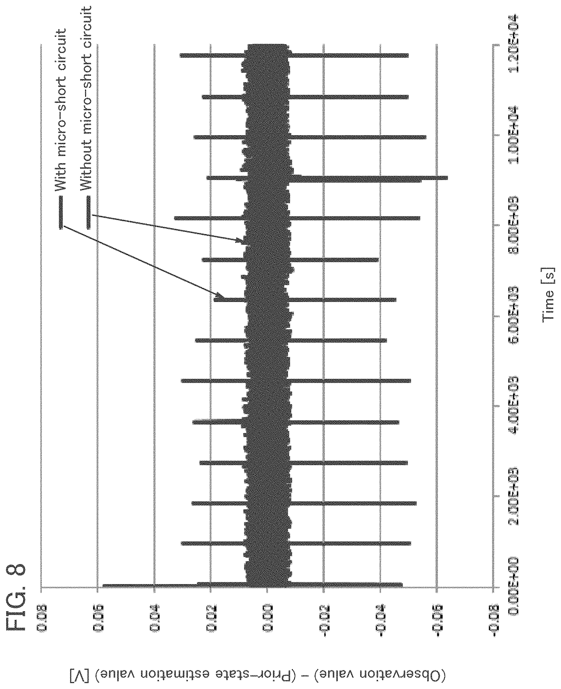
(Embodiment 2)
[0091] In this embodiment, a structure that further uses a neural network (NN) to increase accuracy is described below.
[0092] FIG. 3 is a diagram illustrating an example of a functional block. The difference from Embodiment 1 is that FIG. 3 includes a neural network unit 404. NN in FIG. 3(A) denotes a neural network unit, and its output is LO(k).
[0093] In FIG. 3(A), the portion denoted by the reference numeral 401 is a portion denoting a difference (voltage difference) between an observation value (voltage) and a voltage that is estimated using a prior-state variable, and the value of this voltage difference is input to the neural network unit 404 to determine whether there is an abnormality by comparing with learning data. The accuracy can be further increased by accumulating data input to the neural network unit 404 and making the data part of the learning data.
[0094] FIG. 3(B) is one of the other variations. In the functional block illustrated in FIG. 3(B), the value of voltage difference is input to both the comparator and the neural network (NN), and OR of the output from both of them is selected. In addition, AND may be selected instead of OR.
[0095] FIG. 4(A) is one of the other variations. In the functional block illustrated in FIG. 4(A), the output of the comparator is input to the neural network (NN), and abnormality is determined using the value that is output.
[0096] FIG. 4(B) is one of the other variations. In the functional block illustrated in FIG. 4(B), the output of the comparator is input to the neural network (NN), and abnormality is determined using the value derived from selecting AND of the comparator and the neural network (NN).
[0097] FIG. 5(A) is one of the other variations. In the functional block illustrated in FIG. 5(A), abnormality is sensed using data that has passed through a Kalman gain g(k).
(Embodiment 3)
[0098] In this embodiment, a structure in which accuracy is increased by further using an additional comparator is described below.
[0099] The relationship of the elapsed time and the value of voltage difference was investigated, and it was found that there is an error different from the error when a micro-short circuit occurs. The present inventors have found that an error occurs when switching between charge and discharge in a secondary battery. As illustrated in FIG. 6(A), the terminal current changes at the timing of discharge.
[0100] During the switching between charge and discharge, an overshoot on the positive side is not observed. In contrast, as illustrated in FIG. 6(B), when a micro-short circuit occurs, overshoots occur both on the positive side and the negative side. The overshoot on the positive side is due to corrections of forecast error being reflected in the next step. The overshoot occurs on the negative side first, after which the overshoot occurs on the positive side. Due to this difference, in the case where an overshoot occurs only on the positive side, the case is deemed as an error and it is determined that a micro-short circuit has not occurred.
[0101] Two comparators are provided as shown in FIG. 5(B); an overshoot value on the negative side (REF1) is input to Comparator 1, an overshoot value on the positive side (REF2) is input to Comparator 2, and an AND calculation of an output of the comparator in a previous one step and an output of the comparator in the present is performed using a delay circuit.
[0102] With such a structure, noise in situations such as switching between charge and discharge is removed, and the accuracy of abnormality sensing of micro-short circuits can be increased.
[0103] This embodiment can be freely combined with any of the other embodiments.
(Embodiment 4)
[0104] In this embodiment, an example in which the present invention is applied to an electric vehicle (EV) is described using FIG. 10
[0105] FIG. 10(A) illustrates an example of a block diagram of an electric vehicle.
[0106] In an electric vehicle, a first battery 301 as a secondary battery for main driving and a second battery 311 which supplies electric power to an inverter 312 starting a motor 304 are provided. In this embodiment, an abnormality-monitor unit 300 driven by power supply from the second battery 311 monitors a plurality of secondary batteries constituting the first battery 301 collectively.
[0107] The first battery 301 supplies electric power to in-vehicle parts for 42 V (for a high-voltage system) and the second battery 311 supplies electric power to in-vehicle parts for 14 V (for a low-voltage system). Lead batteries are usually used for the second battery 311 due to cost advantage. Lead batteries have disadvantages compared with lithium-ion secondary batteries in that they have a larger amount of self-discharge and are more likely to degrade due to a phenomenon called sulfation. An advantage of using a lithium-ion secondary battery for the second battery 311 is eliminating the need for maintenance however, if it is used over a long time, for example three years or longer, abnormalities that cannot be determined at the time of manufacturing the battery may occur. In particular, when the second battery 311 that starts the inverter becomes inoperative, the motor cannot be started even when the first battery 301 has remaining capacity; thus, in order to prevent this, in the case where the second battery 311 is a lead storage battery, the second battery is supplied with power from the first battery to constantly maintain a fully-charged state.
[0108] In this embodiment, an example in which a lithium-ion secondary battery is used for both the first battery 301 and the second battery 311 is described. A lead battery or an all-solid-state battery can be used for the second battery 311.
[0109] An example of a cylindrical secondary battery is described with reference to FIG. 12(A) and FIG. 12(B). A cylindrical secondary battery 600 includes, as illustrated in FIG. 12(A), a positive electrode cap (battery lid) 601 on the top surface and a battery can (outer can) 602 on the side and bottom surfaces. The positive electrode cap and the battery can (outer can) 602 are insulated by a gasket (insulating packing) 610.
[0110] FIG. 12(B) illustrates a schematic cross-sectional view of the cylindrical secondary battery. Inside the battery can 602 having a hollow cylindrical shape, a battery element in which a belt-like positive electrode 604 and a belt-like negative electrode 606 are wound with a separator 605 located therebetween is provided. Although not illustrated, the battery element is wound around a center pin. One end of the battery can 602 is closed and the other end thereof is opened. For the battery can 602, a metal having corrosion resistance to an electrolyte solution, such as nickel, aluminum, or titanium, an alloy of such a metal, or an alloy of such a metal and another metal (e.g., stainless steel or the like) can be used. The battery can 602 is preferably covered with nickel, aluminum, or the like to prevent corrosion due to an electrolyte solution. Inside the battery can 602, the battery element in which the positive electrode, the negative electrode, and the separator are wound is interposed between a pair of insulating plates 608 and 609 that face each other. Furthermore, a nonaqueous electrolyte solution (not illustrated) is injected inside the battery can 602 provided with the battery element. The secondary battery is composed of a positive electrode containing an active material such as lithium cobalt oxide (LiCoO.sub.2) or lithium iron phosphate (LiFePO.sub.4), a negative electrode composed of a carbon material such as graphite capable of occluding and releasing lithium ions, a nonaqueous electrolytic solution in which an electrolyte composed of a lithium salt such as LiBF.sub.4 or LiPF.sub.6 is dissolved in an organic solvent such as ethylene carbonate or diethyl carbonate, and the like.
[0111] Since the positive electrode and the negative electrode of the cylindrical secondary battery are wound, active materials are preferably formed on both sides of the current collectors. A positive electrode terminal (positive electrode current collector lead) 603 is connected to the positive electrode 604, and a negative electrode terminal (negative electrode current collector lead) 607 is connected to the negative electrode 606. For both the positive electrode terminal 603 and the negative electrode terminal 607, a metal material such as aluminum can be used. The positive electrode terminal 603 and the negative electrode terminal 607 are resistance-welded to a safety valve mechanism 612 and the bottom of the battery can 602, respectively. The safety valve mechanism 612 is electrically connected to the positive electrode cap 601 through a PTC (Positive Temperature Coefficient) element 611. The safety valve mechanism 612 cuts off the electrical connection between the positive electrode cap 601 and the positive electrode 604 when the increased internal pressure of the battery exceeds a predetermined threshold value. In addition, the PTC element 611 is a thermally sensitive resistor whose resistance increases in the case where temperature rises, and limits the amount of current by increasing the resistance to prevent abnormal heat generation. Barium titanate (BaTiO.sub.3)-based semiconductor ceramic or the like can be used for the PTC element.
[0112] A lithium-ion secondary battery using an electrolyte solution includes a positive electrode, a negative electrode, a separator, an electrolyte solution, and an exterior body. Note that in a lithium-ion secondary battery, the anode (positive electrode) and the cathode (negative electrode) are interchanged in charging and discharging, and the oxidation reaction and the reduction reaction are interchanged; thus, an electrode with a high reaction potential is called the positive electrode and an electrode with a low reaction potential is called the negative electrode. For this reason, in this specification, the positive electrode is referred to as a "positive electrode" or a "+ electrode (plus electrode)" and the negative electrode is referred to as a "negative electrode" or a "- electrode (minus electrode)" in any of the case where charging is performed, the case where discharging is performed, the case where a reverse pulse current is made to flow, and the case where charging current is made to flow. The use of terms such as anode (positive electrode) and cathode (negative electrode) related to oxidation reaction and reduction reaction might cause confusion because the anode and the cathode are reversed in charging and in discharging. Thus, the terms anode (positive electrode) and cathode (negative electrode) are not used in this specification. If the term anode (positive electrode) or cathode (negative electrode) is used, it should be clearly mentioned whether the anode or the cathode is charging or discharging, and corresponds to which of the positive electrode (plus electrode) or the negative electrode (minus electrode).
[0113] A charger is connected to two terminals illustrated in FIG. 12(C), and a storage battery 1400 is charged. In FIG. 12(C), 1406 denotes an electrolyte solution and 1408 denotes a separator. As the charge of the storage battery 1400 proceeds, a potential difference between electrodes increases. The positive direction in FIG. 12(C) is the direction which a current flows from a terminal outside the storage battery 1400 to a positive electrode 1402; from the positive electrode 1402 to a negative electrode 1404 in the storage battery 1400; and from the negative electrode to a terminal outside the storage battery 1400. In other words, the direction in which a charge current flows is regarded as the direction of a current.
[0114] In this embodiment, an example of a lithium-ion secondary battery is shown; however, it is not limited to a lithium-ion secondary battery and a material including an element A, an element X, and oxygen can be used as a positive electrode material for the secondary battery. The element A is preferably one or more selected from the Group 1 elements and the Group 2 elements. As a Group 1 element, for example, an alkali metal such as lithium, sodium, or potassium can be used. As a Group 2 element, for example, calcium, beryllium, magnesium, or the like can be used. As the element X, for example, one or more selected from metal elements, silicon, and phosphorus can be used. The element X is preferably one or more selected from cobalt, nickel, manganese, iron, and vanadium. Typical examples include lithium-cobalt composite oxide (LiCoO.sub.2) and lithium iron phosphate (LiFePO.sub.4).
[0115] The negative electrode includes a negative electrode active material layer and a negative electrode current collector. In addition, the negative electrode active material layer may contain a conductive additive and a binder.
[0116] For the negative electrode active material, an element that enables charge-discharge reaction by alloying and dealloying reactions with lithium can be used. For example, a material containing at least one of silicon, tin, gallium, aluminum, germanium, lead, antimony, bismuth, silver, zinc, cadmium, indium, and the like can be used. Such elements have higher capacity than carbon, and silicon in particular has a high theoretical capacity of 4200 mAh/g.
[0117] In addition, the secondary battery preferably includes a separator. As the separator, for example, a fiber containing cellulose such as paper; nonwoven fabric; a glass fiber; ceramics; a synthetic fiber using nylon (polyamide), vinylon (polyvinyl alcohol-based fiber), polyester, acrylic, polyolefin, or polyurethane; or the like can be used.
[0118] Regenerative energy generated by rolling of tires 316 is transmitted to a motor 304 through a gear 305 and a motor controller 303 and a battery controller 302 charges the second battery 311 or the first battery 301.
[0119] The first battery 301 is mainly used for driving the motor 304 and supplies electric power to in-vehicle parts for 42 V (such as an electric power steering 307, a heater 308, and a defogger 309) through a DC-DC circuit 306. Even in the case where there is a rear motor for the rear wheels, the first battery 301 is used to drive the rear motor.
[0120] The second battery 311 supplies electric power to car parts for 14V (such as an audio 313, a power window 314, and lamps 315) through a DC-DC circuit 310.
[0121] The first battery 301 is composed of a module set including a plurality of secondary batteries. For example, a cylindrical secondary battery 600 illustrated in FIG. 12(A) is used. As illustrated in FIG. 10(B), the cylindrical secondary battery 600 may be interposed between a conductive plate 613 and a conductive plate 614 to form a module. In FIG. 10(B), switches are not illustrated between the secondary batteries. A plurality of secondary batteries 600 may be connected in parallel, connected in series, or connected in series after connecting in parallel. By forming a module including the plurality of secondary batteries 600, large power can be extracted.
[0122] In order to cut off electric power from the plurality of secondary batteries, the secondary batteries in the vehicle include a service plug or a circuit breaker which can cut off a high voltage without the use of equipment; these are provided in the first battery 301. For example, in the case where 48 battery modules which each include two to ten cells are connected directly, a service plug or a circuit breaker is placed between the 24th module and the 25th module.
[0123] FIG. 11 illustrates examples of vehicles each using the abnormality detection system of a secondary battery of one embodiment of the present invention. A secondary battery 8024 of an automobile 8400 illustrated in FIG. 11(A) not only drives an electric motor 8406 but also can supply electric power to a light-emitting device such as a headlight 8401 or a room light (not illustrated). For the secondary battery 8024 in the automobile 8400, the cylindrical secondary batteries 600 illustrated in FIG. 10(B) that are interposed between the conductive plate 613 and the conductive plate 614 to form a module can be used.
[0124] An automobile 8500 illustrated in FIG. 11(B) can be charged when the secondary battery included in the automobile 8500 is supplied with electric power from external charging equipment by a plug-in system, a contactless power feeding system, or the like. FIG. 11(B) illustrates a state in which the secondary battery 8024 incorporated in the automobile 8500 is charged with a ground-based charging apparatus 8021 through a cable 8022. Charging may be performed as appropriate by a given method such as CHAdeMO (registered trademark) or Combined Charging System as a charging method, the standard of a connector, or the like. The charging apparatus 8021 may be a charging station provided in a commercial facility or a power source in a house. For example, with a plug-in technique, the secondary battery 8024 incorporated in the automobile 8500 can be charged by power supply from the outside. Charging can be performed by converting AC power into DC power through a converter such as an AC-DC converter.
[0125] Furthermore, although not illustrated, a power-receiving device can be incorporated in the vehicle, and the vehicle can be charged by being supplied with power from an above-ground power transmitting device in a contactless manner. In the case of this contactless power feeding system, by incorporating a power-transmitting device in a road or an exterior wall, charging is not limited to while the vehicle is stopped but also can be performed while the vehicle is running. In addition, this contactless power feeding system may be utilized to transmit and receive power between vehicles. Furthermore, a solar cell may be provided in the exterior of the vehicle to charge the secondary battery while the vehicle is stopped or while the vehicle is running. For supply of power in such a contactless manner, an electromagnetic induction method or a magnetic resonance method can be used.
[0126] FIG. 11(C) is an example of a motorcycle using the secondary battery of one embodiment of the present invention. A scooter 8600 illustrated in FIG. 11(C) includes a secondary battery 8602, side mirrors 8601, and a direction indicator light 8603. The secondary battery 8602 can supply electricity to the direction indicator light 8603.
[0127] Furthermore, in the scooter 8600 illustrated in FIG. 11(C), the secondary battery 8602 can be held in an under-seat storage 8604. The secondary battery 8602 can be stored in the under-seat storage 8604 even when the under-seat storage 8604 is small.
[0128] For the secondary battery 8602, an all-solid-state battery can be used. The secondary battery 8602 is composed of a plurality of laminated secondary batteries. FIG. 13(D) illustrates an example of a laminated secondary battery that uses an all-solid-state battery.
[0129] A laminated secondary battery 500 illustrated in FIG. 13(D) includes a positive electrode lead electrode 510 and a negative electrode lead electrode 511.
[0130] A procedure for manufacturing the laminated secondary battery will be briefly described. First, a positive electrode and a negative electrode are prepared. The positive electrode includes a positive electrode current collector, and a positive electrode active material layer is formed on a surface of the positive electrode current collector. In addition, the positive electrode includes a region where the positive electrode current collector is partly exposed (hereinafter, such a region is referred to as a tab region). The negative electrode includes a negative electrode current collector, and a negative electrode active material layer is formed on a surface of the negative electrode current collector. In addition, the negative electrode includes a region where the negative electrode current collector is partly exposed, that is, a tab region.
[0131] Then, the negative electrode, a solid electrolyte layer, and the positive electrode are stacked. An example of using five sets of negative electrodes and four sets of positive electrodes is described here. Next, the tab regions of the positive electrodes are bonded to each other, and the positive electrode lead electrode 510 is bonded to the tab region of the positive electrode on the outermost surface. Ultrasonic welding or the like may be used for the bonding, for example. In a similar manner, the tab regions of the negative electrodes are bonded to each other, and the tab region of the negative electrode on the outermost surface is bonded to the negative electrode lead electrode 511.
[0132] Then, the negative electrode, the solid electrolyte layer, and the positive electrode are provided over an exterior body. The solid electrolyte layer may be a material layer containing a solid component with lithium-ion conductivity (e.g., ceramic or the like). As the solid electrolyte layer, for example, a sheet is formed using slurry made from ceramic powder or glass powder. Note that ceramic is defined as a metal or non-metal material of an inorganic compound such as an oxide, a carbide, a nitride, and a boride. Glass is defined as an amorphous material having a glass transition phenomenon, and microcrystalline glass may be called ceramic glass. Ceramic glass, which has crystallinity, can be identified by X-ray diffraction. For the solid electrolyte, an oxide solid electrolyte, a sulfide solid electrolyte, and the like can be used. Each of the positive electrode active material layer and the negative electrode active material layer contains a solid electrolyte and may include a conductive additive. The conductive additive can be any material with electron conductivity such as a carbon material and a metal material.
[0133] For an oxide solid electrolyte used as a positive electrode active material, Li.sub.3PO.sub.4, Li.sub.3BO.sub.3, Li.sub.4SiO.sub.4, Li.sub.4GeO.sub.4, LiNbO.sub.3, LiVO.sub.2, LiTiO.sub.3, LiZrO.sub.3, and the like can be used. Composite compounds thereof such as Li.sub.3BO.sub.3--Li.sub.4SiO.sub.4 can also be used. At least part of the surface of the solid electrolyte may be covered with a coat layer with a thickness of 1 nm or more to 20 nm or less, and as a material of the coat layer, an oxide with lithium-ion conductivity is used.
[0134] Examples of an oxide solid electrolyte used as a negative electrode active material include Nb.sub.2O.sub.5, Li.sub.4Ti.sub.5O.sub.12, and SiO. In this specification and the like, SiO refers to, for example, silicon monoxide. Note that SiO may refer to a material with a higher silicon content than SiO.sub.2, and may be expressed as SiO.sub.x. Here, x preferably has an approximate value of 1. For example, x is preferably more than or equal to 0.2 and less than or equal to 1.5, further preferably more than or equal to 0.3 and less than or equal to 1.2.
[0135] Examples of a sulfide solid electrolyte used as a positive electrode active material include a material containing Li and S, such as Li.sub.7P.sub.3S.sub.11, Li.sub.2S--SiS.sub.2, and Li.sub.2S--P.sub.2S.sub.5.
[0136] Next, the exterior body is bent. Then, the outer portions of the exterior body are bonded. For the exterior body, a laminated film in which metal foil and an organic resin film are stacked such as aluminum foil or stainless steel foil is used; and for the bonding, thermocompression is used, for example. In this manner, the laminated secondary battery 500 illustrated in FIG. 13(D) can be manufactured. Although an example in which one laminated film is used for the bonding is described, two laminated films may be stacked and sealed with the outer edges thereof attached to each other.
[0137] FIG. 13(A) is a conceptual view of a solid-state battery including a solid electrolyte layer 83 between a positive electrode 81 and a negative electrode 82. The solid-state battery include a thin-film-type all-solid-state battery and a bulk-type all-solid-state battery. The thin-film-type all-solid-state battery is obtained by stacking thin films, and the bulk-type all-solid-state battery is obtained by depositing microscopic particles.
[0138] FIG. 13(B) illustrates an example of the bulk-type all-solid-state battery including a particle-state positive electrode active material 87 in the vicinity of the positive electrode 81 and a particle-state negative electrode active material 88 in the vicinity of the negative electrode 82; and the solid-state electrolyte layer 83 is positioned to fill the gaps in between. More than one kind of particles is filled between the positive electrode 81 and the negative electrode 82 with pressure pressing so that gaps are eliminated.
[0139] FIG. 13(C) illustrates an example of a thin-film-type all-solid-state battery. Films of the thin-film-type all-solid-state battery are deposited by a gas phase method (a vacuum evaporation method, a thermal spraying method, a pulsed laser deposition method, an ion plating method, a cold spray method, an aerosol deposition method, and a sputtering method). FIG. 13(C) illustrates an example of fabricating a lithium-ion storage battery in a manner that wiring electrodes 85 and 86 are formed on a substrate 84, the positive electrode 81 is formed on the wiring electrode 85, the solid electrolyte layer 83 is formed on the positive electrode 81, the negative electrode 82 is formed on the solid electrolyte layer 83 and the wiring electrode 86. Examples of the substrate 84 include a ceramic substrate, a glass substrate, a plastic substrate, and a metal substrate.
[0140] This embodiment can be combined with the description of the other embodiments as appropriate.
(Embodiment 5)
[0141] An example of a method for estimating the SOC of a secondary battery is illustrated in FIG. 14. FIG. 14 is a flow chart, and after an abnormality such as a micro-short circuit is detected, forecast error data is created; for example, the mean of normal forecast errors of previous one to four steps is put into the Kalman filter. The SOC can be accurately found even after sensing abnormality.
[0142] When the value of voltage difference obtained from the equation above exceeds a certain threshold value, a comparator or the like outputs a signal, and an abnormality is detected. An abnormality is determined by performing comparison with a voltage signal REF which is a threshold value that is input to the comparator. Data on the timing at which the abnormality is detected is not used in the estimation later, and instead, the mean value of the previous steps is input to an estimation algorithm. When the value of voltage difference obtained from the above Equation 8 falls below the voltage signal REF, it is replaced by the mean value of the previous steps. Therefore, when the value of voltage difference obtained from the above Equation 8 falls below the voltage signal REF that is input to the comparator, the voltage difference is not put into the Kalman filter loop. Instead, a mean value is input to the estimation algorithm, whereby estimation of SOC or the like can be performed with high accuracy even when an abnormality occurs. When data on the timing at which an abnormality such as a micro-short circuit is detected is not used, and instead, the mean value of the previous steps is input to an estimation algorithm, the value of voltage difference obtained in the above Equation 8 approximates to data in the case where a micro-short circuit does not occur.
[0143] FIG. 16 illustrates a specific system diagram for executing the flow chart shown in FIG. 14. In FIG. 16, a charging state estimation device of a secondary battery includes at least the comparator 403, a delay circuit, an AND circuit 405, and a multiplexer 407. A clock signal CLK is input to the AND circuit. A reference signal REF is input to the comparator 403. FIG. 16 is an example and is not particularly limited. The charging state estimation device of a secondary battery that estimates the charging state of the secondary battery includes a sensing means that senses a voltage value of the secondary battery that is to be a first observation value; a calculation unit that calculates an estimated voltage value using a regression model; and a determination unit that finds a difference between the voltage value of the first observation value and the estimated voltage value obtained from a previous time and determines that the secondary battery has an abnormality when the difference exceeds a certain threshold value range. The determination unit includes one or a plurality of comparators, a multiplexer, and a delay circuit. MUX in FIG. 16 denotes a multiplexer. The charging state estimation device of a secondary battery may further include a second sensing means that senses a current value of the secondary battery that is to be a second observation value. In FIG. 16, an FIR (Finite Impulse Response) filter is used. FIG. 17 illustrates an example of a different system diagram. In FIG. 17, an IIR (Infinite Impulse Response) filter is used. In FIG. 17, N represents infinite time which is a value that is sufficiently large in time k.
[0144] Even when data of abnormality that is sensed is not input to the Kalman filter loop, by accurately calculating and reflecting the current that is lost due to a micro-short circuit during abnormality sensing, the value of SOC can be more accurate. FIG. 18 illustrates a flow chart. As shown in FIG. 18, when a value that is small compared with the signal REF in a comparator is output as LO, that is, the value obtained in Equation 8<REF, an abnormality such as a micro-short circuit is deemed to have occurred, and this abnormality is detected
[0145] The data of abnormality that is sensed is a forecast error voltage, and I.sub.micro, which is a current when a micro-short circuit occurs, is obtained using a state equation. This is described below using an equivalent circuit model illustrated in FIG. 15(A) and FIG. 15(B). In FIG. 15(A) and FIG. 15(B), OCV denotes a potential difference during discharge, and V.sub.0, V.sub.1, V.sub.2, and V.sub.3 denote the voltage at each point.
x(k)=[SOC(k)V.sub.1(k)V.sub.2(k)V.sub.3(k)R.sub.0(k)].sup.T Equation 9
[0146] The above equation expresses the state variable x(k) in a circuit in FIG. 15(A). FIG. 15(A) illustrates an equivalent circuit model corresponding to the state before a micro-short circuit occurs.
[0147] In addition, u(k) denotes a current I.sub.BAT(k). u(k) is an input signal, and in the case of a secondary battery, u(k) is a current value.
b = [ T S FCC T S C 1 T S C 2 T S C 3 0 ] T [ Equation 10 ] ##EQU00002##
[0148] b is a constant that composes a state equation, and T.sub.S is a sampling period.
x ( k + 1 ) = [ 1 0 0 0 0 0 1 - T S C 1 R 1 0 0 0 0 0 1 - T S C 2 R 2 0 0 0 0 0 1 - T S C 3 R 3 0 0 0 0 0 0 ] x ( k ) + [ T S FCC T S C 1 T S C 2 T S C 3 0 ] u ( k ) [ Equation 11 ] ##EQU00003##
[0149] The above equation is a state equation of a Kalman filter. Note that the resistances R.sub.1, R.sub.2, and R.sub.3, capacities C.sub.1, C.sub.2, and C.sub.3, and a full-charge capacity FCC in the above equation may be expanded and be included in the state variable x(k).
[0150] Next, a state when a micro-short circuit occurs is regarded as an equivalent circuit model illustrated in FIG. 15(B), and calculation procedures are described below.
V.sub.0(k+1)=R.sub.0(k).times.I.sub.0 Equation 12
[0151] The equation above is a relational equation in the case where the time when a micro-short circuit occurs is represented by k+1. In addition, the current at each point can be expressed by the following.
I.sub.1=I.sub.2=I.sub.3=I.sub.BAT(k) Equation 13
[0152] The voltage V.sub.1 applied to the resistance R.sub.1 and the capacity C.sub.1 is expressed by the following equation.
V 1 ( k + 1 ) = ( 1 - T S C 1 R 1 ) .times. V 1 ( k ) + I BAT ( k ) C 1 [ Equation 14 ] ##EQU00004##
[0153] The voltage V.sub.2 applied to the resistance R.sub.2 and the capacity C.sub.2 is expressed by the following equation.
V 2 ( k + 1 ) = ( 1 - T S C 2 R 2 ) .times. V 2 ( k ) + I BAT ( k ) C 2 [ Equation 15 ] ##EQU00005##
[0154] The voltage V.sub.3 applied to the resistance R.sub.3 and the capacity C.sub.3 is expressed by the following equation.
V 3 ( k + 1 ) = ( 1 - T S C 3 R 3 ) .times. V 3 ( k ) + I BAT ( k ) C 3 [ Equation 16 ] ##EQU00006##
[0155] In the case where in the above equations, a numerical value shown below is significantly smaller than 1 or accuracy is not substantially required, the value shown below may be 1.
1 - T S C N R N [ Equation 17 ] ##EQU00007##
[0156] In the case where the above equation is 1, the amount of calculation can be reduced.
I micro = I 1 - I 0 = I BAT ( k ) - V 0 ( k + 1 ) R 0 ( k ) = I BAT ( k ) - V IN - { V 1 ( k + 1 ) + V 2 ( k + 1 ) + V 3 ( k + 1 ) + V ocv ( k ) } R 0 ( k ) [ Equation 18 ] ##EQU00008##
[0157] A current when a micro-short circuit occurs (I.sub.micro) can be found by calculating the above equation. As shown in the above equation, the current when a micro-short circuit occurs is calculated by using a voltage V.sub.IN including R.sub.0, which is estimated in the previous one step, OCV and the forecast error voltage, and an observation value of the current I.sub.BAT. R.sub.0(k) is a covariance of the forecast error
SOC ( k ' ) = SOC ( k ) - T S .times. I micro FCC [ Equation 19 ] ##EQU00009##
[0158] SOC(k) in the above equation corresponds to SOC data inside the Kalman filter at the prior-estimate prediction step. The current when a micro-short circuit occurs can be reflected in the SOC inside the Kalman filter by replacing the value on the left side in the equation above with the SOC data inside the Kalman filter just before the filtering step.
[0159] For the estimation processing that performs calculation of the SOC, in transferring a program that can execute the above equation to a microcomputer or a microprocessor, the SOC can be calculated.
[0160] This embodiment can be combined with the other embodiments as appropriate.
EXAMPLE 1
[0161] FIG. 7 illustrates an example of a functional block that performs calculation of the Kalman filter. Except for not having a comparator, FIG. 7 is the same as Embodiment 1. A value of voltage difference denoted by a reference numeral 401 in FIG. 7 is important in the case where a micro-short circuit occurs, and abnormality sensing of a secondary battery is performed by monitoring this value.
[0162] A simulation is conducted using data where a pseudo-current that generates a micro-short circuit periodically is created.
[0163] FIG. 8 shows the simulation results; the horizontal axis represents time and the vertical axis represents voltage difference, specifically a difference (voltage difference) between an observation value (voltage) and a voltage that is estimated using a prior-state variable.
[0164] In FIG. 8, data in which overshoots are observed periodically on the positive side and on the negative side is data with a micro-short circuit. Data in which an overshoot is observed only on the negative side is data without a micro-short circuit, and is a comparative example. The point where an overshoot is observed only on the negative side corresponds to the point where a voltage changes when switching from charge to discharge. In the comparative example in FIG. 8, the point where overshoots are observed only on the negative side is -0.0213 V, hence when a value larger than this value, for example, when -0.03 V is set as the threshold value, the value can be regarded as an error of margin and be prevented from being sensed as an abnormality.
[0165] Note that in FIG. 9, data in FIG. 8 is edited, and the vertical axis is split into left and right for easy viewing. Data used for verification in FIG. 8 is data in which waveforms of a micro-short circuit are input regularly, and although in FIG. 8 the micro-short circuit is generated 13 times, in an actual secondary battery, micro-short circuits occur randomly, and the sizes of the peaks change depending on the state of usage (charge or discharge) of the secondary battery. In any case, when a micro-short circuit is sensed, the degradation of the secondary battery is accelerated or the secondary battery becomes unusable; hence, notifying users of a warning of sensing is useful. Although the cause of the occurrence of a micro-short circuit has not been identified yet, there is a theory that this is due to entry of metal powder at manufacture, and even though an abnormality is not sensed right after manufacture, it is possible that in repeating charge and discharge the abnormal portion (conductive portion) is formed and grown, leading to the occurrence of the micro-short circuit. When a secondary battery in which a micro-short circuit has occurred is charged and discharged, degradation progresses rapidly, and the secondary battery may suddenly become unusable. Thus, the method of the present invention capable of sensing a micro-short circuit is useful.
[0166] In a Kalman filter, input values of a battery are input to a battery equivalent circuit model and output values are compared; when there is a difference, a Kalman gain is applied to the difference and feedback is given, after which the battery equivalent circuit model is corrected so that the error becomes minimum. This is repeated in succession.
[0167] Note that the Kalman filter is a system in which data is matched in succession, and the errors near the beginning in FIG. 8 and FIG. 9 can be ignored.
[0168] In the value of voltage difference denoted by the reference numeral 401 in FIG. 7, -0.0631 V is set as the minimum value and +0.0324 V is set as the maximum value. In addition, a peak point that is close to 0 in a point at which a micro-short circuit is generated is -0.0386 V on the negative side and +0.0186 V on the positive side. Hence, in order to sense all micro-short circuits, the sensing may be performed using a comparator or the like with the threshold value set at -0.0386 V on the negative side and +0.0186 V on the positive side. Since these values vary depending on the secondary battery that is used, simulation is performed as appropriate in advance using the characteristics data of the secondary battery that is used, and the threshold value may be determined on the basis of the results.
[0169] Note that the simulation results in FIG. 8 and FIG. 9 are obtained by using LTspice (Simulation program with integrated circuit emphasis), which is a circuit simulator provided by Analog Devices.
REFERENCE NUMERALS
[0170] 1 comparator, 2 comparator, 81: positive electrode, 82: negative electrode, 83: solid electrolyte layer, 84: substrate, 85: wiring electrode, 86: wiring electrode, 87: positive electrode active material, 88: negative electrode active material, 300: abnormality-monitor unit, 301: battery, 302: battery controller, 303: motor controller, 304: motor, 305: gear, 306: DC-DC circuit, 307: electric power steering, 308: heater, 309: defogger, 310: DC-DC circuit, 311: battery, 312: inverter, 313: audio, 314: power window, 315: lamps, 316: tire, 400: micro-short circuit model, 401: reference numeral, 402: delay circuit, 403: comparator, 404: neural network unit, 405: AND circuit, 407: multiplexer, 600: secondary battery, 601: positive electrode cap, 602: battery can, 603: positive electrode terminal, 604: positive electrode, 605: separator, 606: negative electrode, 607: negative electrode terminal, 608: insulating plate, 609: insulating plate, 611: PTC element, 612: safety valve mechanism, 613: conductive plate, 614: conductive plate, 1400: storage battery, 1402: positive electrode, 1404: negative electrode, 8021: charging apparatus, 8022: cable, 8024: secondary battery, 8400: automobile, 8401: headlight, 8406: electric motor, 8500: automobile, 8600: scooter, 8601: side mirror, 8602: secondary battery, 8603: direction indicator light, 8604: under-seat storage
* * * * *
D00000
D00001
D00002
D00003
D00004
D00005
D00006
D00007
D00008
D00009
D00010
D00011
D00012
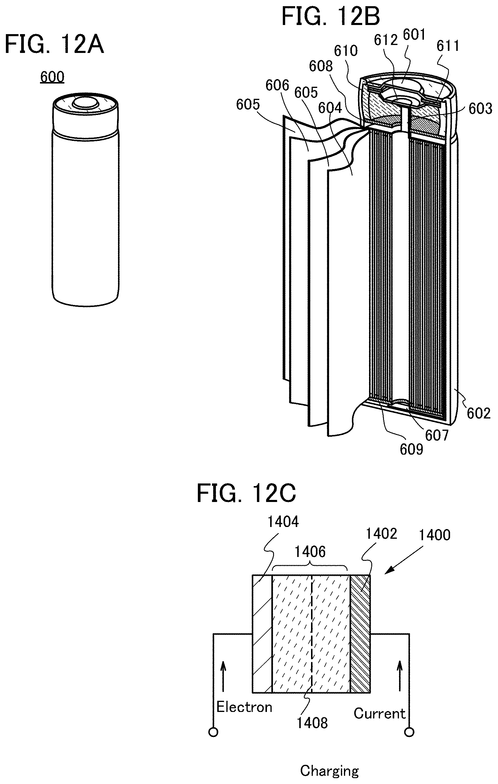
D00013

D00014
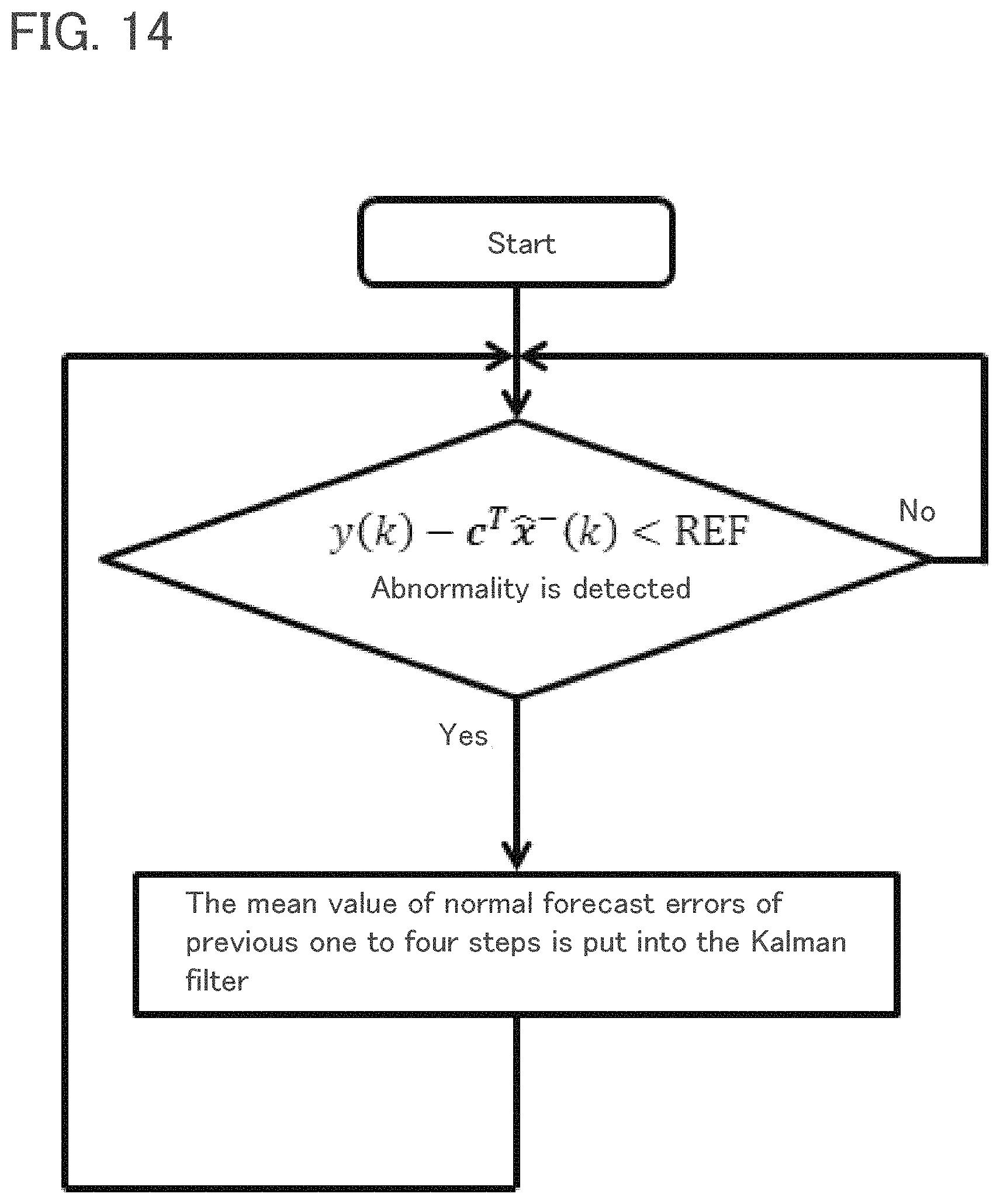
D00015
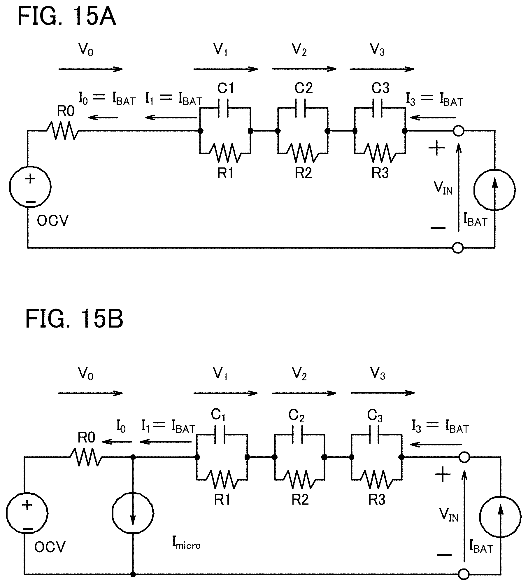
D00016
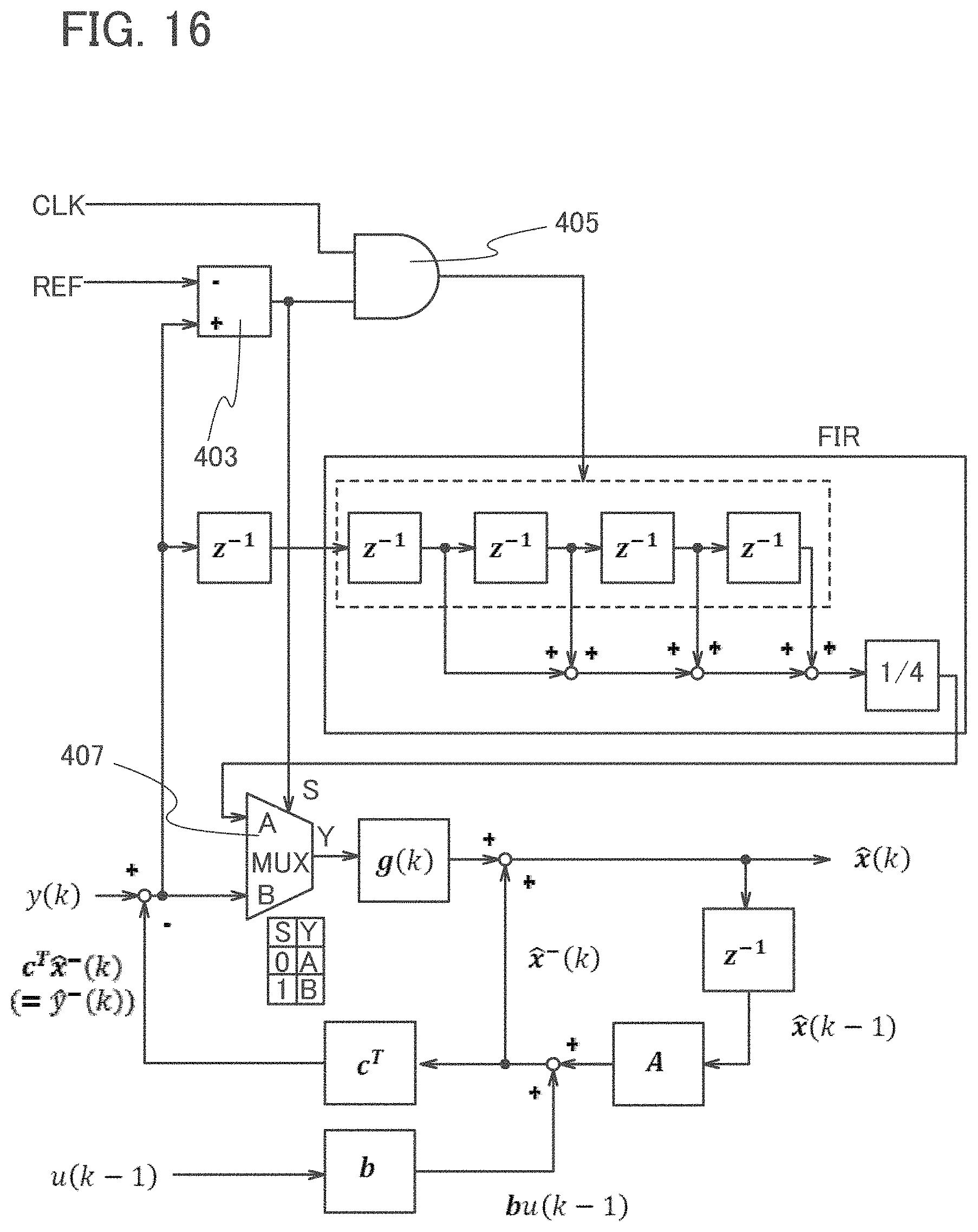
D00017
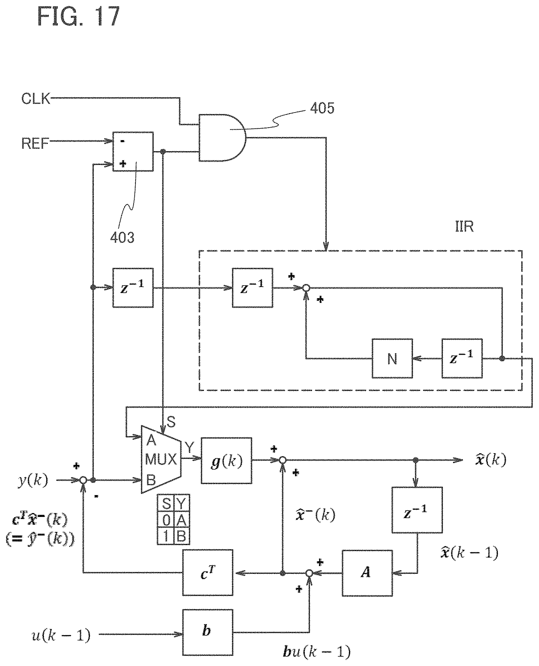
D00018


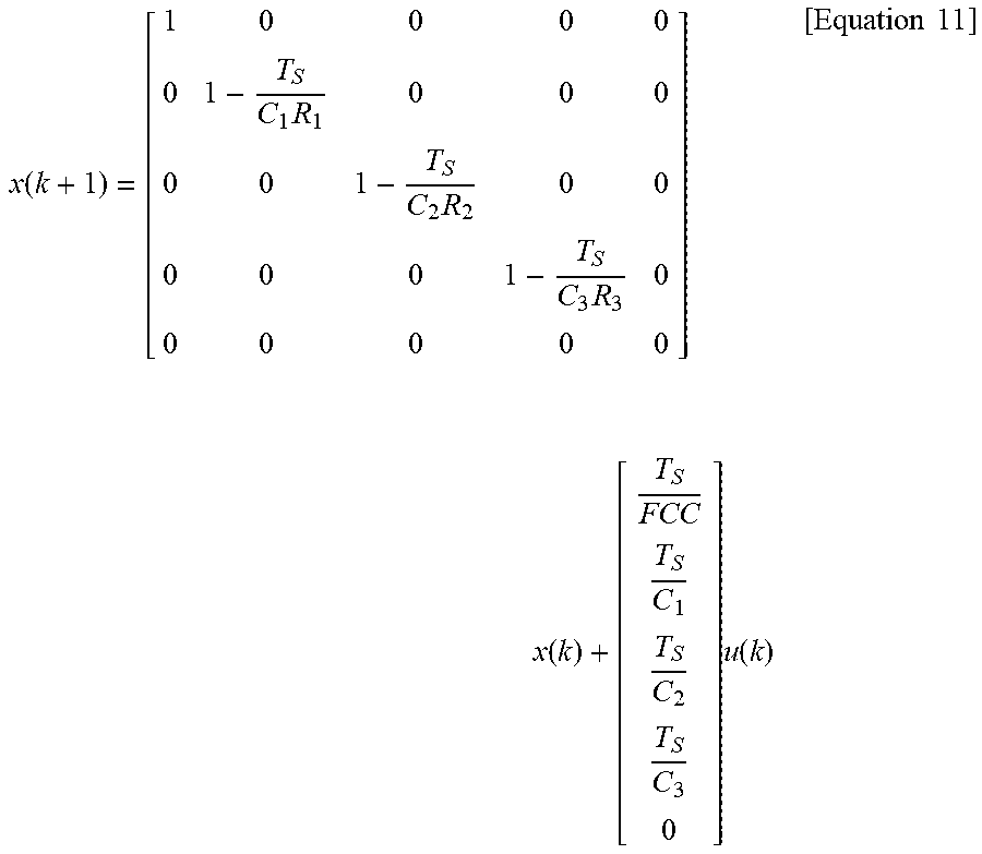


XML
uspto.report is an independent third-party trademark research tool that is not affiliated, endorsed, or sponsored by the United States Patent and Trademark Office (USPTO) or any other governmental organization. The information provided by uspto.report is based on publicly available data at the time of writing and is intended for informational purposes only.
While we strive to provide accurate and up-to-date information, we do not guarantee the accuracy, completeness, reliability, or suitability of the information displayed on this site. The use of this site is at your own risk. Any reliance you place on such information is therefore strictly at your own risk.
All official trademark data, including owner information, should be verified by visiting the official USPTO website at www.uspto.gov. This site is not intended to replace professional legal advice and should not be used as a substitute for consulting with a legal professional who is knowledgeable about trademark law.