Air Conditioning Device
Liang; Chih-Chuan ; et al.
U.S. patent application number 16/819179 was filed with the patent office on 2020-11-12 for air conditioning device. This patent application is currently assigned to Chizentek Inc.. The applicant listed for this patent is Chizentek Inc.. Invention is credited to Chih-Chuan Liang, Wen-Hung Lo.
| Application Number | 20200355385 16/819179 |
| Document ID | / |
| Family ID | 1000004988372 |
| Filed Date | 2020-11-12 |


| United States Patent Application | 20200355385 |
| Kind Code | A1 |
| Liang; Chih-Chuan ; et al. | November 12, 2020 |
AIR CONDITIONING DEVICE
Abstract
An air conditioning device is provided. The air conditioning device includes a power supplier, a compressor driver, a fan driver, a temperature sensor, a vibration sensor, and an operation processing controller. The power supplier has an input end receiving an input power source and generates a first operating power source and a second operating power source according to the input power source. The compressor driver operates according to the first operating power source to generate a first drive signal to drive a compressor. The fan driver operates according to the first operating power source to generate a second drive signal to drive a fan. The vibration sensor detects vibration information of the air conditioning device. The operation processing controller operates according to the second operating power source and controls the power supplier according to the vibration information to determine whether to cut off supply of the first operating power source to ensure safe operation of the air conditioning device.
| Inventors: | Liang; Chih-Chuan; (Hsinchu City, TW) ; Lo; Wen-Hung; (New Taipei City, TW) | ||||||||||
| Applicant: |
|
||||||||||
|---|---|---|---|---|---|---|---|---|---|---|---|
| Assignee: | Chizentek Inc. Hsinchu County TW |
||||||||||
| Family ID: | 1000004988372 | ||||||||||
| Appl. No.: | 16/819179 | ||||||||||
| Filed: | March 16, 2020 |
Related U.S. Patent Documents
| Application Number | Filing Date | Patent Number | ||
|---|---|---|---|---|
| 62818111 | Mar 14, 2019 | |||
| Current U.S. Class: | 1/1 |
| Current CPC Class: | F24F 11/38 20180101; F25B 2700/2116 20130101; F25B 2700/151 20130101; F24F 11/64 20180101; F25B 49/022 20130101; F24F 11/88 20180101; F25B 2700/21151 20130101; F24F 11/89 20180101; F25B 2700/21152 20130101 |
| International Class: | F24F 11/38 20060101 F24F011/38; F24F 11/89 20060101 F24F011/89; F24F 11/88 20060101 F24F011/88; F25B 49/02 20060101 F25B049/02 |
Claims
1. An air conditioning device, configured to control an air conditioner, comprising: a power supplier, comprising an input end receiving an input power source and generating a first operating power source and a second operating power source according to the input power source; a compressor driver, operating according to the first operating power source to generate a first drive signal to drive a compressor; a fan driver, operating according to the first operating power source to generate a second drive signal to drive a fan; a vibration sensor, detecting vibration information of the air conditioner; a temperature sensor, detecting a plurality of pieces of temperature information of the air conditioner; a current sensor, detecting current information of the compressor and the fan; a voltage sensor, detecting voltage information in the air conditioning device; and an operation processing controller, coupled to the power supplier, the compressor driver, the fan driver, the vibration sensor, the temperature sensor, the current sensor, and the voltage sensor, operating according to the second operating power source, controlling the power supplier according to the vibration information, the temperature information, the current information, and the voltage information to determine whether to cut off supply of the first operating power source or to stop operation of the compressor and the fan.
2. The air conditioning device according to claim 1, wherein the operation processing controller generates a control command via a protection circuit as hardware or by executing software.
3. The air conditioning device according to claim 1, wherein the compressor driver transmits abnormality information to the operation processing controller, and the operation processing controller generates a control command according to the abnormality information.
4. The air conditioning device according to claim 3, wherein the abnormality information comprises temperature information of the compressor driver and current information of the compressor driver.
5. The air conditioning device according to claim 1, wherein the fan driver transmits abnormality information to the operation processing controller, and the operation processing controller generates a control command according to the abnormality information.
6. The air conditioning device according to claim 5, wherein the abnormality information comprises temperature information of the fan and current information of the fan.
7. The air conditioning device according to claim 1, wherein the plurality of pieces of temperature information comprise a suction end temperature of the compressor, a discharge end temperature of the compressor, an ambient temperature of 1the air conditioner, and a condenser temperature of the air conditioner.
Description
CROSS-REFERENCE TO RELATED APPLICATION
[0001] This application claims the priority benefit of U.S. provisional application Ser. No. 62/818,111, filed on Mar. 14, 2019. The entirety of the above-mentioned patent application is hereby incorporated by reference herein and made a part of this specification.
BACKGROUND
Technical Field
[0002] The disclosure relates to an air conditioning device, and in particular, to a protection mechanism of an air conditioning device.
Description of Related Art
[0003] In today's society, air conditioning devices have become commonly used devices. The air conditioning devices can be configured to regulate the temperature, humidity and airflow distribution of air. Air in the environment may thereby be maintained in a comfortable state. Based on the characteristic that the air conditioning devices need to work for a long time, electrical and mechanical equipment of the air conditioning devices may fail due to environmental factors and/or deterioration of components. Therefore, it is a very important subject to monitor the air conditioning devices in real time and to maintain a certain degree of appropriateness of the air conditioning devices.
SUMMARY
[0004] The disclosure is directed to provide a protection mechanism with different reaction rates for an air conditioning device so as to effectively maintain a rate of appropriateness of the air conditioning device.
[0005] According to the embodiments of the disclosure, an air conditioning device is configured to control an air conditioner. The air conditioning device includes a power supplier, a compressor driver, a fan driver, a vibration sensor, a temperature sensor, a current sensor, a voltage sensor, and an operation processing controller. The power supplier has an input end receiving an input power source and generates a first operating power source and a second operating power source according to the input power source. The compressor driver operates according to the first operating power source to generate a first drive signal to drive a compressor. The fan driver operates according to the first operating power source to generate a second drive signal to drive a fan. The vibration sensor detects vibration information of the air conditioner. The temperature sensor detects a plurality of pieces of temperature information of the air conditioner. The current sensor detects current information of the compressor and the fan. The voltage sensor detects voltage information in the air conditioning device. The operation processing controller is coupled to the power supplier, the compressor driver, the fan driver, the temperature sensor, the current sensor, the voltage sensor, and the vibration sensor, operates according to the second operating power source, and controls the power supplier according to the vibration information, the temperature information, the current information, and the voltage information to determine whether to cut off supply of the first operating power source or stop operation of the compressor and the fan.
BRIEF DESCRIPTION OF THE DRAWINGS
[0006] The accompanying drawings are included to provide a further understanding of the disclosure, and are incorporated in and constitute a part of this specification. The accompanying drawings illustrate embodiments of the disclosure and, together with the description, serve to explain the principles of the disclosure.
[0007] FIG. 1 is a schematic diagram of an air conditioning device according to an embodiment of the disclosure.
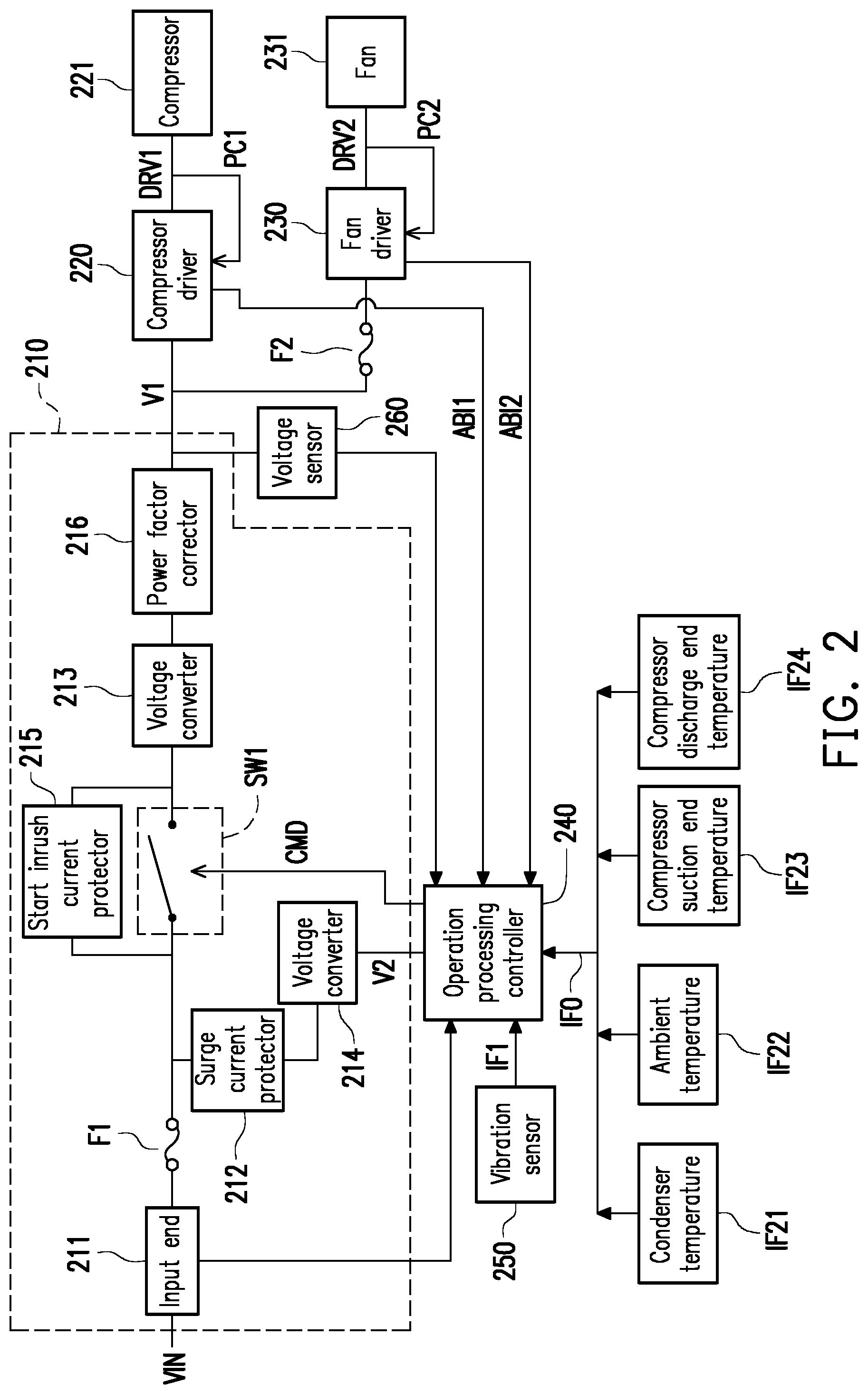
[0008] FIG. 2 is a schematic diagram of an air conditioning device according to another embodiment of the disclosure.
[0009] FIG. 3 is a start timing sequence diagram of multiple protection actions of the air conditioning device according to the embodiments of the disclosure.
DESCRIPTION OF THE EMBODIMENTS
[0010] Exemplary embodiments of the disclosure are described in detail, and examples of the exemplary embodiments are shown in the accompanying drawings. Whenever possible, the same component symbols are used in the drawings and descriptions to indicate the same or similar parts.
[0011] Please refer to FIG. 1, FIG. 1 is a schematic diagram of an air conditioning device according to an embodiment of the disclosure. An air conditioning device 100 includes a power supplier 110, a compressor driver 120, a fan driver 130, a vibration sensor 150, and an operation processing controller 140. The power supplier 110 has an input end receiving an input power source VIN. The power supplier 110 generates a first operating power source V1 and a second operating power source V2 according to the input power source VIN. The compressor driver 120 and the fan driver 130 are coupled to the power supplier 110 to receive the first operating power source V1 and operates according to the first operating power source V1. Based on the first operating power source V1, the compressor driver 120 is configured to generate a drive signal DRV1 to drive a compressor 121, and the fan driver 130 is configured to generate a drive signal DRV2 to drive a fan 131.
[0012] The vibration sensor 150 is disposed on the air conditioning device 100. The vibration sensor 150 detects vibration information IF of the air conditioning device 100. The operation processing controller 140 is coupled to the power supplier 110 and the vibration sensor 150. The operation processing controller 140 receives the second operating power source V2 and operates according to the second operating power source V2. Based on the second operating power source V2, the operation processing controller 140 receives the vibration information IF and controls the power supplier 110 according to the vibration information IF to determine whether to cut off the supply of the first operating power source V1 of the power supplier 110. In the present embodiment, the level of the first operating power source V1 is greater than the level of the second operating power source V2.
[0013] Specifically, the vibration sensor 150 is configured to sense a vibration state that occurs when the air conditioning device 100 operates. The vibration information IF generated by the vibration sensor 150 can indicate the magnitude of position offset of the air conditioning device 100 caused by vibration. In addition, the operation processing controller 140 can determine whether an absolute value of a peak value of the position offset of the air conditioning device 100 is greater than a pre-determined threshold value according to the vibration information IF, and the operation processing controller 140 can inform the power supplier 110 that the supply of the first operating power source V1 needs to be cut off at this time through a generated control command CMD when the absolute value of the position offset of the air conditioning device 100 is greater than the above-mentioned threshold value. On the contrary, if the absolute value of the peak value of the position offset of the air conditioning device 100 is not greater than the above-mentioned threshold value, the power supplier 110 may continue to supply the first operating power source V1.
[0014] Incidentally, in the present embodiment, the operation processing controller 140 may perform interpretation of the vibration information IF by executing software and generates the corresponding control command CMD through a software execution result. That is, in the present embodiment, when the air conditioning device 100 vibrates excessively, the operation processing controller 140 may start a protection action in several mini-seconds (ms) through the software and cut off the supply of the first operating power source V1 of the power supplier 110 via the control command CMD. Alternatively, in other embodiments, the operation processing controller 140 may not cut off the supply of the first operating power source V1 of the power supplier 110 and directly send a command to stop the operation of the fan 131 and the compressor 121.
[0015] The air conditioning device 100 of the embodiment of the disclosure further includes a voltage sensor 170, a temperature sensor 180, and a current sensor 160. The voltage sensor 170, the temperature sensor 180, and the current sensor 160 are coupled to the operation processing controller 140. The voltage sensor 170, the temperature sensor 180, and the current sensor 160 provide detected voltage information, temperature information, and current information to the operation processing controller 140 respectively as a basis for how the operation processing controller 140 starts a protection mechanism. Herein, the voltage sensor 170 and the current sensor 160 can detect voltage and current states of one or more electronic components in an air conditioner and generate voltage information and current information by detecting whether the voltage and current states are abnormal or not. The temperature sensor 180 may be disposed at one or more locations inside the air conditioner and generates temperature information by detecting a temperature state of each part when the air conditioner works.
[0016] Referring to FIG. 2 next, FIG. 2 is a schematic diagram of an air conditioning device according to another embodiment of the disclosure. An air conditioning device 200 includes a power supplier 210, a compressor driver 220, a fan driver 230, a vibration sensor 250, an operation processing controller 240, a voltage sensor 260, and a fuse F2. In the present embodiment, the power supplier 210 includes an input end 211, a fuse F1, a surge current protector 212, voltage converters 213 and 214, a switch SW1, a start inrush current protector 215, and a power factor corrector 216. The input end 211 is configured to receive an input power source VIN. The fuse Fl is coupled in series between the input end 211 and the surge current protector 212. The surge current protector 212 is configured to reduce a surge current generated on the input power source VIN. The voltage converter 214 receives the input power source VIN via the surge current protector 212 and performs a voltage conversion action for the input power source VIN to generate a second operating power source V2. In the present embodiment, the voltage converter 214 may be an AC to DC voltage converter.
[0017] The switch SW1 is coupled onto a path in which the power supplier 210 outputs a first operating power source V1. The switch SW1 may be turned on or off in accordance with a control command CMD transmitted by the operation processing controller 240. The start inrush current protector 215 is connected to two ends of the switch SW1 in a cross-over mode and configured to reduce an inrush current generated by the air conditioning device 200 in the starting process. The voltage converter 213 is coupled to an output end of the start inrush current protector 215 and performs a voltage conversion action for the input power source VIN to generate the first operating power source V1 when the switch SW1 is turned on. Herein, the level of the first operating power source V1 is greater than the level of the second operating power source V2.
[0018] In addition, the power factor corrector 216 is coupled to an output end providing the first operating power source V1 so as to perform a power factor correction action of the first operating power source V1.
[0019] In another aspect, the power supplier 210 provides the first operating power source V1 to the compressor driver 220 and the fan driver 230. The compressor driver 220 and the fan driver 230 generate drive signals DRV1 and DRV2 respectively based on the first operating power source V1 and make the drive signals DRV1 and DRV2 drive a compressor 221 and a fan 231 respectively. In the present embodiment, the fuse F2 is disposed in the power supplier 210 and the fan driver 230.
[0020] It is worth mentioning that in the present embodiment, when a peak current provided by the drive signal DRV1 is excessively high, the compressor 221 may feed back a peak current protection signal PC1 to the compressor driver 220 and make the compressor driver 220 cut off the supply of the drive signal DRV1. Similarly, when a peak current provided by the drive signal DRV2 is excessively high, the fan 231 may feed back a peak current protection signal PC2 to the fan driver 230 and make the fan driver 230 cut off the supply of the drive signal DRV2.
[0021] Here, the protection actions performed by the compressor driver 220 and the fan driver 230 are performed by means of hardware circuits. Accordingly, the protection actions performed by the compressor driver 220 and the fan driver 230 may be accomplished in several micro-seconds (us).
[0022] In another aspect, the fuse F1 and the fuse F2 may be fused respectively when an overcurrent phenomenon occurs in the input power source VIN and the first operating power source V1. When the overcurrent phenomenon occurs in the input power source VIN, the fuse F1 may be fused to stop the receiving of the input power source VIN. When the overcurrent phenomenon occurs in the first operating voltage V1, the fuse F2 may be fused to prevent the fan driver 230 from receiving the first operating power source V1, and the purpose of circuit protection is achieved. Here, the fusing action of the fuse F1 and the fuse F2 may be completed in several seconds, which is another form of hardware protection action.
[0023] In the present embodiment, the compressor driver 220 and the fan driver 230 are coupled to the operation processing controller 240. The compressor driver 220 and the fan driver 230 transmit abnormality information ABI1 and ABI2 to the operation processing controller 240 respectively. The abnormality information ABI1 includes abnormality information of temperature information of the compressor driver 220 and current information of the compressor driver 220. The abnormality information ABI2 includes abnormality information of temperature information of the fan driver 230 and current information of the fan driver 230.
[0024] The operation processing controller 240 may generate a control command CMD based on the abnormality information ABI1 and ABI2 by executing software. When an abnormality occurs in at least one of the compressor driver 220, the fan driver 230, the compressor 221, and the fan 231, the switch SW1 is turned off by the control command CMD. By turning off the switch SW1, the supply of the first operating power source V1 may be stopped, and the appropriateness state of hardware components is maintained.
[0025] In another aspect, the operation processing controller 240 may additionally receive temperature information IFO such as a condenser temperature IF21, an ambient temperature IF22, a compressor input end temperature IF23, and a compressor output end temperature IF24. The operation processing controller 240 also receives vibration information IF1 of the air conditioning device 200 through the vibration sensor 250. The operation processing controller 240 may perform operation on the abnormality information ABI1 and ABI2, the temperature information IFO, and the vibration information IF1 by executing software, thereby generating the control command CMD.
[0026] In the present embodiment, the voltage sensor 260 may be coupled to an end point where the power supplier 210 generates the first operating power source V1 and senses the level of the first operating power source V1 to transmit a sensed result to the operation processing controller 240. The operation processing controller 240 may also generate a control command according to whether an overvoltage phenomenon occurs in the level of the first operating power source V1.
[0027] The above-mentioned operation processing controller 240 may be a processor with operational capability.
[0028] Referring to FIG. 2 and FIG. 3 hereinafter, FIG. 3 is a start timing sequence diagram of multiple protection actions of the air conditioning device according to the embodiments of the disclosure. In time intervals T1 and T3, protection actions are performed by hardware in the air conditioning device. In a time interval T2, a protection action is started by software executed by the operation processing controller. Herein, the protection actions performed by the compressor driver 220 and the fan driver 230 according to peak current protection signals PCI and PC2 fed back by the compressor 221 and the fan 231 respectively may occur at time T11 in the time interval T1. The protection action performed by the surge current protector 212 may then occur at time T12 relatively later than time T11 in the time interval T1. In addition, at time T21 in the time interval T2, the operation processing controller 240 may make determination based on the current information transmitted by the compressor driver 220 and the fan driver 230 and start a protection mechanism when an average current of at least one of the drive signals DRV1 and DRV2 is greater than a pre-determined threshold value. Next, at time T22 in the time interval T2, the operation processing controller 240 may make determination and determine whether to start the protection mechanism according to the temperature information transmitted by the compressor driver 220 and the fan driver 230 and the temperature information IFO received by the operation processing controller 240. At time T23 in the time interval T2, the operation processing controller 240 may start the protection mechanism according to the vibration information IF1 generated by the vibration sensor 250. In the present embodiment, the time T21, T22, and T23 may occur sequentially.
[0029] The fuses disposed in the compressor 221, the fan 231 and, the power supplier 210 may be fused at time T31 to T33 respectively in the time interval T3 when an abnormality phenomenon (overcurrent) occurs, and the protection mechanism is started.
[0030] It can be seen from the above descriptions that in the air conditioning device according to the embodiments of the disclosure, the protection mechanism with multiple different rates is provided. The air conditioning device may be effectively prevented from being damaged due to at least one of a plurality of different reasons such as over-temperature, overcurrent, and vibration, and the working appropriateness of the air conditioning device is effectively maintained.
[0031] Finally, it should be noted that the foregoing embodiments are merely used for describing the technical solutions of the disclosure, but are not intended to limit the disclosure.
[0032] Although the disclosure is described in detail with reference to the foregoing embodiments, a person of ordinary skill in the art should understand that, modifications may still be made to the technical solutions in the foregoing embodiments, or equivalent replacements may be made to some or all of the technical features; and such modifications or replacements will not cause the essence of corresponding technical solutions to depart from the scope of the technical solutions in the embodiments of the disclosure.
* * * * *
D00000
D00001
D00002
D00003
XML
uspto.report is an independent third-party trademark research tool that is not affiliated, endorsed, or sponsored by the United States Patent and Trademark Office (USPTO) or any other governmental organization. The information provided by uspto.report is based on publicly available data at the time of writing and is intended for informational purposes only.
While we strive to provide accurate and up-to-date information, we do not guarantee the accuracy, completeness, reliability, or suitability of the information displayed on this site. The use of this site is at your own risk. Any reliance you place on such information is therefore strictly at your own risk.
All official trademark data, including owner information, should be verified by visiting the official USPTO website at www.uspto.gov. This site is not intended to replace professional legal advice and should not be used as a substitute for consulting with a legal professional who is knowledgeable about trademark law.