Exhaust Gas Purification Apparatus And Exhaust Gas Purification Method Using Same
Eom; Yong Seok ; et al.
U.S. patent application number 16/079051 was filed with the patent office on 2020-11-12 for exhaust gas purification apparatus and exhaust gas purification method using same. This patent application is currently assigned to Korea Electric Power Corporation. The applicant listed for this patent is Korea Electric Power Corporation. Invention is credited to Yong Seok Eom, Kwang Beom Hur, Jun Han Kim, Joong Won Lee, Jung Bin Lee.
| Application Number | 20200355103 16/079051 |
| Document ID | / |
| Family ID | 1000004988483 |
| Filed Date | 2020-11-12 |

| United States Patent Application | 20200355103 |
| Kind Code | A1 |
| Eom; Yong Seok ; et al. | November 12, 2020 |
EXHAUST GAS PURIFICATION APPARATUS AND EXHAUST GAS PURIFICATION METHOD USING SAME
Abstract
The present invention relates to an exhaust gas purification apparatus and an exhaust gas purification method using the same. According to a specific embodiment., the exhaust gas purification apparatus comprises: a diesel oxidation catalyst (DOC) unit for convening nitrogen oxides (NO.sub.8), contained in an exhaust gas introduced therein through a gas inlet portion, into nitrogen dioxide (NO.sub.2); a composite diesel particulate filter (DPF) unit connected to the rear end of the DOC unit through an inflow line and removing harmful components including particulate substances and nitrogen oxides from the exhaust gas discharged from the DOC unit and introduced therein; and a circulation line disposed in the inflow line so as to introduce the exhaust gas discharged from the DOC unit into the gas inlet portion.
| Inventors: | Eom; Yong Seok; (Daejeon, KR) ; Lee; Jung Bin; (Daejeon, KR) ; Kim; Jun Han; (Daejeon, KR) ; Lee; Joong Won; (Daejeon, KR) ; Hur; Kwang Beom; (Daejeon, KR) | ||||||||||
| Applicant: |
|
||||||||||
|---|---|---|---|---|---|---|---|---|---|---|---|
| Assignee: | Korea Electric Power
Corporation Naju-si, Jeollanam-do KR |
||||||||||
| Family ID: | 1000004988483 | ||||||||||
| Appl. No.: | 16/079051 | ||||||||||
| Filed: | November 29, 2016 | ||||||||||
| PCT Filed: | November 29, 2016 | ||||||||||
| PCT NO: | PCT/KR2016/013831 | ||||||||||
| 371 Date: | August 22, 2018 |
| Current U.S. Class: | 1/1 |
| Current CPC Class: | F01N 3/106 20130101; F01N 3/2066 20130101; F01N 2610/02 20130101; F01N 2570/14 20130101; B01D 2255/1021 20130101; F01N 3/035 20130101; B01D 53/9418 20130101; F01N 9/002 20130101 |
| International Class: | F01N 3/035 20060101 F01N003/035; F01N 3/20 20060101 F01N003/20 |
Foreign Application Data
| Date | Code | Application Number |
|---|---|---|
| Sep 23, 2016 | KR | 10-2106-0122396 |
Claims
1. An exhaust gas purification apparatus, comprising: a diesel oxidation catalyst (DOC) unit which is configured to convert nitrogen oxides (NOx) contained in exhaust gas input through a gas inlet into NO.sub.2; a composite diesel particulate filter (DPP) unit which is connected to a rear end of the DOC unit via an input line, and configured to remove harmful components including particulate muter (PM) and NOx due to the input of exhaust gas discharged from the DOC unit; and a circulation line configured to input the exhaust gas discharged from the DOC unit to the gas inlet.
2. The exhaust gas purification apparatus according to claim 1, wherein the composite DPF unit comprises one or more supports among silicon carbide (SiC), cordierite (2MgO 2Al.sub.2O.sub.3 5SiO.sub.2), aluminum titanate (Al.sub.2TiO.sub.5) and needle-like mullite (Al.sub.2SiO.sub.5).
3. The exhaust gas purification apparatus according to claim 1, wherein the composite DPF unit further comprises a selective catalytic reduction (SCR) layer.
4. The exhaust gas purification apparatus according, to claim 3, wherein the SCR layer is prepared by supporting an active ingredient and a promoter on a support containing a titanium dioxide-zirconia compound, and the active ingredient includes a rare earth element-vanadate compound, and the promoter includes a transition metal oxide.
5. The exhaust gas purification apparatus according to claim 4, wherein the support contains the titanium dioxide and zirconia at a molar ratio of about 1:0.8 to about 1:1.5.
6. The exhaust was purification apparatus according to claim 4, wherein the SCR layer comprises about 80 wt % to about 90 wt % of the support, about 1 wt % to about 13 wt % of the active ingredient and about 1 wt % to about 15 wt % of the promoter with respect to a total weight thereof.
7. The exhaust gas purification apparatus according to claim 1, wherein the composite DPF unit does not include a heat source, and is configured to remove a harmful component by NO.sub.2 in the input exhaust gas.
8. The exhaust gas purification apparatus according to claim 1, wherein the exhaust gas input to the composite DPI unit has a NO.sub.2 conversion rate of about 0.2 or more, defined by Equation 1 below: NO.sub.2 conversion rate=NO.sub.2 mass/NOx mass in exhaust gas [Equation 1]
9. The exhaust gas purification apparatus according to claim 8, further comprising: a concentration measuring unit configured to measure a NOx concentration of the exhaust gas in the input line, wherein information on the NOx concentration measured at the concentration measuring unit is transmitted to a control unit electrically connected with the concentration measuring unit, and when the exhaust gas NO.sub.2 conversion rate deduced using the measured NOx concentration is less than about 0.2, the control unit is provided at the circulation line, and configured to control a circulation valve electrically connected therewith such that the exhaust gas is input to the gas inlet.
10. The exhaust gas purification apparatus according to claim 1, wherein the DOC unit is prepared by supporting about 3 g/ft.sup.3 to about 7 g/ft.sup.3 of platinum on a porous alumina support,
11. A method for purifying exhaust gas, comprising: converting nitrogen oxides (NOx) in exhaust gas into NO.sub.2 by inputting exhaust gas to a diesel oxidation catalyst (DOC) unit through a gas inlet; and removing harmful components including particulate matter (PM) and NOx in the exhaust gas by inputting the exhaust gas to a composite diesel particulate filter (DPF) unit via an input line, wherein the exhaust gas discharged from the DOC unit is input to the gas inlet through a circulation line provided at the input line.
12. The method according to claim 11, wherein the composite DPF unit does not include a heat source and is configured to remove a harmful component by the input exhaust gas.
13. The method according to claim 11, wherein the exhaust gas input to the composite DPF unit has a NO.sub.2 conversion rate of about 0.2 or more, defined by Equation 1 below: NO.sub.2 conversion rate=NO.sub.2 mass/NOx mass in exhaust gas [Equation 1]
14. The method according, to claim 13, wherein a concentration measuring unit configured to measure a NOx concentration of the exhaust gas is further provided at the input line, information on the NOx concentration measured at the concentration measuring unit is transmitted to a control unit electrically connected with the concentration measuring unit, and when the exhaust gas NO.sub.2 conversion rate deduced using the measured NOx concentration is less than about 0.2, the control unit is provided at the circulation line, and configured to control a circulation valve connected therewith such that the exhaust as is input to the gas inlet.
Description
TECHNICAL FIELD
[0001] The present invention relates to an exhaust gas purification apparatus and a method for purifying exhaust gas using the same,
BACKGROUND ART
[0002] Diesel exhaust gas discharged from a diesel engine contains hydrocarbons, nitrogen oxides (NOx) and particulate matter (PM). As an apparatus for treating such diesel exhaust gas, an apparatus consisting of a diesel particulate filter (DPF) involved in active regeneration of PM stacked on a filter using an external heat source (a burner, an electric heater, etc.) after capturing PM in the diesel exhaust gas using the filter, and selective catalytic reduction (SCR) which causes a reaction between a reducing agent (urea) and NOx over a catalyst to remove NOx at the rear of the DPF has been developed,
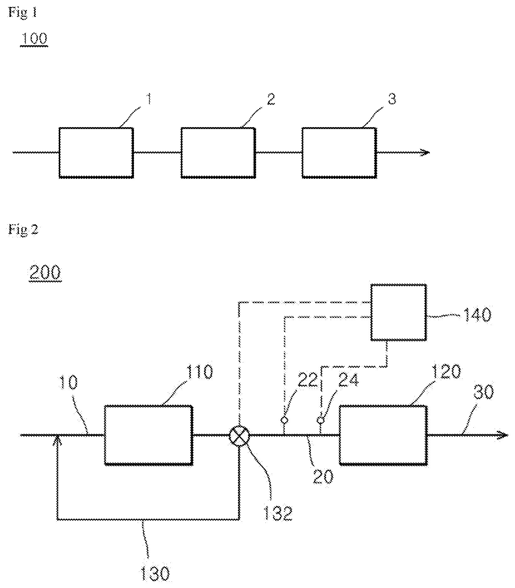
[0003] FIG. 1 illustrates a conventional exhaust gas purification apparatus. Referring to FIG. 1, an exhaust gas purification apparatus 100 sequentially includes a diesel oxidation catalyst unit 1, a DPF unit 2 and an SCR unit 3. The diesel oxidation catalyst (DOC) is included upstream of the DPF to remove PM by oxidation by removing hydrocarbons and converting nitric oxide (NO) among NOx into nitrogen dioxide (NO.sub.2). A method for performing passive regeneration of PM in the DPF without an external heat source has also been developed. In this case, to convert NO into nitrogen dioxide (NO.sub.2), expensive precious metal catalysts such as platinum (Pt) and palladium (Pd) are generally used, and to improve a conversion rate, a large amount of the precious metal catalysts has to be used. In addition, in order to smoothly oxidize PM, since a NO.sub.2 proportion among total NOx has to be increased, it is necessary to include a means for reducing an amount of a precious metal catalyst used and for increasing a NO.sub.2 conversion rate.
[0004] In addition, among, catalysts in the SCR installed a rear of the DPF, a metal oxide-based catalyst and a V.sub.2O.sub.5--WO.sub.3/TiO.sub.2-based catalyst have low NOx removal activity and very hydrothermal stability at 500.degree. C. or higher, and therefore, in active regeneration in the DPF, the catalysts are irreversibly damaged over time. Particularly, a system consisting of DOC-DPF-SCR unit processes has a complicated process and a high hack pressure, resulting in a decrease in engine efficiency, and therefore it is difficult to perform operational control and to stably operate the entire system.
[0005] The prior art relating to the present invention is disclosed in Korean Unexamined Patent Application Publication No. 2016-4032504 (published on Mar. 24, 2016, Title of the Invention: Apparatus for treating exhaust gas discharged from marine diesel engine).
DISCLOSURE
Technical Problem
[0006] An object of the present invention is to provide an exhaust gas purification apparatus having, excellent energy efficiency and economic feasibility during operation thereof.
[0007] Another object of the present invention is to provide an exhaust gas purification apparatus having excellent efficiency in processing a pollutant contained in diesel exhaust gas.
[0008] Still another object of the present invention is to provide an exhaust gas purification apparatus which enables passive regeneration of a composite DPF.
[0009] Yet another object of the present invention is to provide an exhaust gas purification apparatus which is able to reduce an amount of catalysts used in a diesel gas purifier.
[0010] Yet another object of the present invention is to provide an exhaust gas purification apparatus which enables compactness and a smaller size.
[0011] Yet another object of the present invention is to provide a method for purifying exhaust gas using the exhaust gas purification apparatus.
Technical Solution
[0012] One aspect of the present invention relates to an exhaust gas purification apparatus. In one exemplary embodiment, the exhaust gas purification apparatus includes a DOC unit which is configured to convert NOx contained in exhaust gas input through a gas inlet into NO.sub.2; a composite DPF unit which is connected to a rear end of the DOC unit via an input line, and removes harmful components including PM and NOx due to input of exhaust gas discharged from the DOC unit; and a circulation line which is provided at the input line and configured to input the exhaust gas discharged from the DOC unit to a gas inlet.
[0013] In one exemplary embodiment, the composite DPF unit may include one or more supports among silicon carbide (SIC), cordierite (2MgO 2Al.sub.2O.sub.3 5SiO.sub.2), aluminum titanate (Al.sub.2TiO.sub.5) and needle-like mullite (Al.sub.2SiO.sub.5).
[0014] In one exemplary embodiment, the composite DPF unit may further include a selective catalytic reduction (SCR) layer.
[0015] In one exemplary embodiment, the SCR layer may be prepared by supporting an active ingredient and a promoter in a support containing a titanium dioxide-zirconia compound, the active ingredient may include a rare earth element-vanadate compound, and the promoter may include a transition metal oxide.
[0016] In one exemplary embodiment, the support may contain the titanium dioxide and zirconia at a molar ratio of about 1:0.8 to about 1:1.5.
[0017] In one exemplary embodiment, with respect to the total weight of the SCR layer, about 80 wt % to about 90 wt % of a support, about 1 wt % to about 13 wt % of an active ingredient and about 1 wt % to about 15 wt % of a promoter may be included.
[0018] In one exemplary embodiment, the composite DPF unit may not include a heat source, and may remove a harmful component by. NO.sub.2 in the input exhaust gas.
[0019] In one exemplary embodiment, the exhaust gas input into the composite DPF unit may have a NO.sub.2 conversion rate of about 0.2 or more, defined by Equation 1 below:
NO.sub.2 conversion rate=NO.sub.2 mass/NOx mass in exhaust gas [Equation 1]
[0020] In one exemplary embodiment, at the input line, a concentration measuring unit configured to measure a NOx concentration of the exhaust gas in the input line may be further provided, and information on the NOx concentration measured at the concentration measuring unit may be transmitted to a control unit electrically connected with the concentration measuring unit, and when the exhaust gas NO.sub.2 conversion rate deduced using the measured NOx concentration is less than about 0.2, the control unit may be provided at the circulation line, and configured to control a circulation valve electrically connected therewith such that the exhaust gas is input to the gas inlet.
[0021] In one exemplary embodiment, in the DOC unit, about 3 g/ft.sup.3 to about 7 g/ft.sup.3 of platinum may be supported on a porous alumina support.
[0022] Another aspect of the present invention relates to a method for purifying exhaust gas using the exhaust gas purification apparatus. In one exemplary embodiment, the method for purifying exhaust gas includes: converting NOx in exhaust gas into NO.sub.2 by inputting exhaust gas to a DOC unit through a gas inlet: and removing harmful components including PM and NOx in the exhaust gas by inputting the exhaust gas to a composite DPF unit via an input line, wherein the exhaust gas discharged from the DOC unit is input to the gas inlet through a circulation line provided at the input line.
[0023] In one exemplary embodiment, the composite DPF unit may not include a heal source, and may be configured to remove a harmful component by the input exhaust gas.
[0024] In one exemplary embodiment, the exhaust gas input to the composite DPF unit may have a NO.sub.2 conversion rate of about 0.2 or more, defined by Equation 1 below:
NO.sub.2 conversion rate=NO.sub.2 mass/NOx mass in exhaust gas [Equation 1]
[0025] In one exemplary embodiment, at the input line, a concentration measuring unit configured to measure a NOx concentration in the exhaust gas is further provided, and information on the NOx concentration measured at the concentration measuring unit may be transmitted to a control unit electrically connected with the concentration measuring unit. When the exhaust gas NO.sub.2 conversion rate deduced using the measured NOx concentration is less than about 0.2, the control unit may be provided at the circulation line, and configured to control a circulation valve electrically connected therewith such that the exhaust gas is input to the gas inlet.
Advantageous Effects
[0026] Due to integration of a DPF unit and an SCR unit and exclusion of a heat source such as a heater essentially included in a conventional DPF unit, an exhaust gas purification apparatus of the present invention removes a harmful component including PM by passive regeneration occurring due to exhaust gas containing a high concentration of NO.sub.2 without regeneration in the DPF by a heat source, and therefore, the exhaust gas purification apparatus can have excellent energy efficiency and economic feasibility during operation thereof, and excellent efficiency in processing a pollutant contained in diesel exhaust gas. reduce the amount of a catalyst used in a diesel gas purifier, and can be manufactured to be compact and smaller.
DESCRIPTION OF DRAWINGS
[0027] FIG. 1 illustrates a conventional exhaust gas purification apparatus.
[0028] FIG. 2 illustrates an exhaust gas purification apparatus according to an exemplary embodiment of the present invention.
BEST MODEL
[0029] In the description of the present invention, when a detailed description on the related known technology or configurations is determined to unnecessarily obscure the subject matter of the present invention, the detailed description will be omitted.
[0030] Moreover, the terms to be described below are defined in consideration of functions in an embodiment of the present invention, and may vary according to a user, the intention or custom of an operator, Therefore, the definitions should be based on the contents spanning the entire specification.
Exhaust Gas Purification Apparatus
[0031] One aspect of the present invention relates to an exhaust gas purification apparatus. FIG. 2 illustrates an exhaust gas purification apparatus according to an exemplary embodiment of the present invention. Referring to FIG. 2, an exhaust gas purification apparatus 200 includes a DOC unit 110 configured to convert NOx contained in the exhaust gas input through a gas inlet 10 into NO.sub.2; a composite DPF unit 120 which is connected to a rear end of the DOC unit 110 via an input line 20, and configured to remove harmful components including PM and NOx due to the input of the exhaust gas discharged from the DOC unit 110; and a circulation line 130 which is provided at the input line 20 and configured to input the exhaust gas discharged from the DOC unit 110 to the gas inlet 10.
DOC Unit
[0032] The DOC unit 110 is configured to convert (or oxidize) nitrogen monoxide (NO) among NOx in the exhaust gas into NO.sub.2. In one exemplary embodiment, in the DOC unit 110, about 3 g/ft.sup.3 to about 7 g/ft.sup.3 of platinum may be supported on a porous alumina support. For example, the DOC unit 110 may be formed in a honeycomb shape in which about 4 g/ft.sup.3 to about 6 g/ft.sup.3 of platinum is supported on the porous alumina (Al.sub.2O.sub.3) support having a thickness of about 2 nm to about 4 nm. According, to the amount of the supported catalyst, about 10% of NO among NOx generally contained in the diesel engine exhaust gas may be converted into NO.sub.2. In the present invention, the DOC unit 110 may minimize an amount of the supported catalyst and enhance a NO.sub.2 conversion rate, thereby exhibiting an excellent effect of reducing costs,
Composite DPF Unit
[0033] The composite DPF unit 120 is connected to a rear end of the DOC unit 110 via the input line 20, and configured to remove harmful components including PM and NOx due to the input of the exhaust gas discharged from the DOC unit 110. In one exemplary embodiment, in the composite DPF unit, the gas purified by removing the harmful component in the composite DPF unit may be discharged outside through an outlet 30.
[0034] In one exemplary embodiment, the composite DPF unit 120 may include one or more supports among silicon carbide (SiC), cordierite (2MgO 2Al.sub.2O.sub.3 5SiO.sub.2), aluminum titanate (Al.sub.2TiO.sub.5) and needle-like mullite (Al.sub.2SiO.sub.5). When such a type of support is included, the composite DPF unit 120 may have an excellent effect of removing NOx and PM. For example, the composite DPF unit 120 may include one or more selected from silicon carbide (SiC), cordierite (2MgO 2Al.sub.2O.sub.35SiO.sub.2), aluminum titanate (Al.sub.2TiO.sub.5) and needle-like mullite (Al.sub.2SiO.sub.5) as a support and have a honeycomb shape with a pore size of about 10 .mu.m to about 30 .mu.m. The "size" used herein is defined as "maximum length."
[0035] Referring to FIG. 2, a reducing agent inlet 24 may be further included upstream of the composite DPF unit such that a reducing agent is input therethrough. In one exemplary embodiment, the reducing agent is input to the composite DPF unit 120 through the reducing agent inlet 24 to have a reaction with. NOx in the exhaust gas such that the NOx is converted into nitrogen and moisture and removed, The reducing agent may include urea.
[0036] In one exemplary embodiment, the composite DPF unit 120 may further include an SCR layer.
[0037] In the SCR layer, an active ingredient and a promoter may be supported on a support containing a titanium dioxide-zirconia compound, the active ingredient may include a rare earth element-vanadate compound, and the promoter may include a transition metal oxide.
[0038] When the titanium dioxide-zirconia compound is applied as the support, a binary oxide (T--O--Zr) structure is formed such that a surface acid point is increased, and transformation of titanium dioxide front an anatase structure to a rutile structure is prevented at a high temperature, and therefore excellent catalytic activity may be obtained even at a high temperature.
[0039] In one exemplary embodiment, the support may contain the titanium dioxide (TiO.sub.2) and zirconia (ZrO.sub.2) at a molar ratio of about 1:0.8 to about 1:1.5. In this molar ratio range, excellent physical strength and thermal stability of the SCR layer, and excellent efficiency in removing the harmful components including NOx and PM may be achieved. For example, a molar ratio of the titanium dioxide and the zirconia may be about 1.1.
[0040] In one exemplary embodiment, the support may be included at about 80 wt % to about 90 wt % based on the total weight of the SCR layer. When the support is included in the above weight range, it easily supports the active ingredient, and has an increased specific surface area, excellent reactivity and a high NOx conversion rate at a high temperature. For example, the support may be included at about 80, 81. 82, 83, 84, 85, 86, 87, 88, 89 or 90 wt %.
[0041] The active ingredient may increase catalyst activity and enhance the NOx-to-NO.sub.2 conversion rate at a high temperature. In one exemplary embodiment, the active ingredient may include vanadate or a rare earth element-vanadate compound.
[0042] In one exemplary embodiment, the rare earth element-vanadate compound may include one or more rare earth elements including scandium, yttrium, and lanthanides including lanthanum (La) to lutetium (Lu). For example, as the rare earth element-vanadate compound, one or more compounds selected from terbium-vanadate (TbVO.sub.4), erbium-vanadate (ErVO.sub.4), cerium-vanadate (CeVO.sub.4), lanthanum-vanadate (LaVO.sub.4), gadolinium-vanadate (GdVO.sub.4), praseodymium-vanadate. (PrVO.sub.4), neodymium-vanadate (NdVO.sub.4), promethium-vanadate (PmVO.sub.4), samarium-vanadate (SmVO.sub.4), europium-vanadate (EuVO.sub.4), dysprosium-vanadate (DyVO.sub.4), holmium-vanadate (HoVO.sub.4), thulium-vanadate (TmVO.sub.4), ytterbium-vanadate (YbVO.sub.4) and lutetium-vanadate (LuVO.sub.4) may be included. When the rare earth element-vanadate compound is applied, excellent efficiency in enhancing catalytic activity is achieved, and thus the NOx-to-NO.sub.2 conversion rate may be enhanced at a high temperature. In one exemplary embodiment, as the rare earth element-vanadate compound, one or more compounds selected from cerium-vanadate (CeVO.sub.4) and terbium-vanadate (TbVO.sub.4) may be included.
[0043] In one exemplary embodiment, the active ingredient may be contained at about 1 wt % to about 13 wt % based on the total weight of the SCR layer. When the active ingredient is contained in the above range, excellent SCR efficiency may be achieved. For example, the active ingredient may be contained at about 1, 2, 3, 4, 5, 6, 7, 8, 9, 10, 11, 12 or 13 wt %.
[0044] In one exemplary embodiment, the rare earth element-vanadate compound may contain vanadate and a rare earth element at a weight ratio of about 1:1 to about 1:5. In this range, excellent efficiency in removing NOx it exhaust gas may be achieved,
[0045] The promoter may be contained to improve physical strength, such as durability of an active material, and SCR efficiency. In one exemplary embodiment, the promoter may include a transition metal oxide. In one exemplary embodiment, as the transition metal oxide, one or more of molybdenum oxide (MoO.sub.3) and mugs ten oxide (WO.sub.3) may be included.
[0046] In one exemplary embodiment, the promoter may be contained at about 1 wt % to about 15 wt % based on the total weight of the SCR layer. When the promoter is contained in this range, excellent SCR efficiency may be achieved. For example, the promoter may be contained at about 1, 2, 3, 4, 5, 6, 7, 8, 9, 10, 11, 12, 13, 14 or 15 wt %.
[0047] In one exemplary embodiment, the exhaust gas input to the composite DPF unit 120 may have a NO.sub.2 conversion rate of about 0.2 or more, defined by Equation 1 below:
NO.sub.2 conversion rate=NO.sub.2 mass/NOx mass in exhaust gas [Equation 1]
[0048] When the conversion rate is about 0.2 or more, the composite DPF unit 120 may have excellent efficiency in removing harmful components including PM and NOx. For example, the conversion rate of the exhaust gas input to the composite DPF unit 120 may be about 0.5 or more. In another example, the conversion rate may be about 0.5 to about 1. In still another example, the conversion rate may be about 0.5 to 0.9. For example, the conversion rate may be about 0.2, 0.25, 0.3.0.35, 0.4, 0.45, 0.5, 0,55, 0.6, 0.65, 0,7, 0.75, 0.8, 0.85 or 0.9.
Circulation Line
[0049] In one exemplary embodiment, at the input line 20 according to an exemplary embodiment of the present invention, a circulation line 130 configured to input the exhaust gas discharged from the DOC unit 110 through the gas inlet is provided. Referring to FIG. 2, a rear of the DOC unit 110, a concentration measuring unit 120 configured to measure the concentration of NOx such as NO and NO.sub.2 in the exhaust gas may be further included,
[0050] For example, using the NOx concentration measured at the concentration measuring unit 120, the NO.sub.2 conversion rate may be deduced according to Equation 1.
[0051] Referring to FIG. 2, the exhaust gas purification apparatus 200 may further include a control unit 140 electrically connected with a circulation valve 132, the concentration measuring unit 22, the reducing agent inlet 24 and a back-pressure valve (not shown) and controlling them. For example, information on a NOx concentration in the exhaust gas measured at the concentration measuring unit 22 is transmitted to the control unit 140, such that the circulation valve 132 may be controlled by the control unit 140 and a flow rate may be controlled. According to the conversion rate (NO.sub.2/NOx) according to Equation 1, the exhaust gas discharged from the DOC unit may be input to the gas inlet by controlling the circulation valve 132 provided at the circulation line 130,
[0052] In one exemplary embodiment, at the input line 20, the concentration measuring unit 22 configured to measure the concentration of NOx in the exhaust gas is further provided, information on the NOx concentration measured at the concentration measuring unit 22 is transmitted to the control unit 140 electrically connected with the concentration measuring unit 22. When the exhaust gas NO.sub.2 conversion rate deduced in the control unit 140 using the measured NOx concentration is about less than 0.2, the control unit 140 may be provided at the input line 20, and configured to control the circulation valve 132 electrically connected with the control unit 140 such that the exhaust gas is input to the gas inlet 10, For example, when the conversion rate is about less than 0.5, the exhaust gas may be input to the gas inlet 10. When the exhaust gas is input through the gas inlet as described above, the NO.sub.2 content in the exhaust gas discharged from the DOC unit may be increased, and passive regeneration in the composite DPF unit may be easily realized.
[0053] Due to integration of a DPF unit and an SCR unit and exclusion of a heat source such as a heater essentially included in a conventional DPF unit, the exhaust gas purification apparatus of the present invention may enable oxidative removal (or regeneration) using a high concentration of nitrogen dioxide in exhaust gas without regeneration in a composite DPF caused by a heat source. Therefore, the exhaust gas purification apparatus can have excellent energy efficiency and economic feasibility during operation thereof, and excellent efficiency in processing a pollutant contained in diesel exhaust gas, reduce the amount of a catalyst used in a diesel gas purifier, and can be manufactured to be compact and smaller.
Method for Purifying Exhaust Gas Using Exhaust Gas Purification Apparatus
[0054] Another aspect of the present invention relates to a method for purifying exhaust gas using the exhaust gas purification apparatus. In one exemplary embodiment, the method for purifying exhaust gas includes: converting NOx in exhaust gas into NO.sub.2 by inputting exhaust gas to a DOC unit through a gas inlet; and removing harmful components including PM and NOx in the exhaust gas, by inputting the exhaust gas to a composite DPF unit via an input line, wherein the exhaust gas discharged from the DOC unit is input to the gas inlet through a circulation line provided at the input line.
[0055] In one exemplary embodiment, the composite DPF unit may not include a heat source and can be configured to remove harmful components by the input exhaust gas.
[0056] In one exemplary embodiment, the exhaust gas input to the composite DPI unit may have a NO.sub.2 conversion rate of about 0.2 or more, defined by Equation 1 below:
NO.sub.2 conversion rate=NO.sub.2 mass/NOx mass in exhaust gas [Equation 1]
[0057] When the conversion rate is 0.2 or more, excellent efficiency in removing harmful components including PM and NOx in the composite DPF unit may be obtained. For example, the conversion rate of the exhaust gas input to the composite DPF unit may be about 0,5 or more. in another example, the conversion rate may be about 0.5 to about 1. In still another example, the conversion rate may be about 0.5 to 0.9. For example, the conversion rate may be about 0.2, 0.25, 0.3, 0.35, 0.4, 0.45, 0.5, 0.55, 0.6, 0.65, 0.7, 0.75, 0.8, 0.85 or 0.9.
[0058] In one exemplary embodiment, at the input line, a concentration measuring unit configured to measure the concentration of NOx in the exhaust gas may be further provided, information on the NOx concentration measured at the concentration measuring unit may be transmitted to the control unit electrically connected with the concentration measuring unit, and when the exhaust: gas NO.sub.2 conversion rate deduced using the measured NOx concentration is about less than 0.2, the control unit may be provided at the circulation line, and configured to control a circulation valve electrically connected therewith such that the exhaust gas is input to the gas inlet.
Mode for Invention
[0059] Hereinafter, configurations and actions of the present invention will be described in further detail with reference to exemplary examples of the present invention. However, these examples are merely provided as preferable examples, and it is to be understood that the present invention is not limited to the following examples in any way.
[0060] Hereinafter, configurations and actions of the present invention will be described in further detail with reference to exemplary examples of the present invention. However, these examples are merely provided as preferable examples, and it is to be understood that the present invention is not limited to the following examples in any way.
PREPARATION EXAMPLE 1
[0061] A honeycomb-shaped support was manufactured by applying titanium dioxide (TiO.sub.2) as a support of an SCR layer.
PREPARATION EXAMPLE 2
[0062] A support was manufactured by the same method as described in Preparation Example 1, except that titanium dioxide (TiO.sub.2) and zirconia (ZrO.sub.2) were applied at a molar ratio of 1:0.1.
PREPARATION EXAMPLE 3
[0063] A support was manufactured by the same method as described in Preparation Example 1, except that titanium dioxide (TiO.sub.2) and zirconia (ZrO.sub.2) were applied at a molar ratio of 1:0.5.
PREPARATION EXAMPLE 4
[0064] A support was manufactured by the same method as described in Preparation Example 1, except that titanium dioxide (TiO.sub.2) and zirconia (ZrO.sub.2) were applied at a molar ratio of 1:1.
PREPARATION EXAMPLE 5
[0065] A support wits manufactured by the same method as described in Preparation Example 1, except that only zirconia (ZrO.sub.2) was applied.
[0066] Specific surface areas (m.sup.2/g) of the supports manufactured according to Preparation Examples 1 to 5, which were measured by a BET method, are shown in Table 1.
TABLE-US-00001 TABLE 1 Specific surface area Classification (m.sup.2/g @400.degree. C.) Preparation Example 1 83 Preparation Example 2 152 Preparation Example 3 182 Preparation Example 4 234 Preparation Example 5 196
[0067] Referring to Table 1, it ran be seen that the support containing titanium dioxide (TiO.sub.2) and zirconia (ZrO.sub.2) in a molar ratio of 1:1 has the highest specific surface area.
EXAMPLES AND COMPARATIVE EXAMPLES
[0068] SCR preparation: Components used in the preparation of SCR included in the composite DPF unit of the present invention are as follows.
[0069] (a) Support; The support manufactured by Preparation Example 4 was used.
[0070] (b) Active material: (b1) Cerium-vanadate (CeVO.sub.4; containing cerium:vanadate=2.5:1 weight ratio) was used. (b2) Terbium-vanadate (TbVO.sub.4; containing terbium:vanadate=2.5:1 weight ratio) was used.
[0071] (c) Promoter: (c1) Tungsten oxide (WO.sub.3) was used. (c2) Molybdenum oxide (MoO.sub.3) was used.
Example 1
[0072] SCR was prepared by stepwise supporting the active material and the promoter on the content of the support shown in Table 1 below by impregnation, drying the resulting support at 100 and plasticizing the support at 500.degree. C. for 2 to 3 hours.
Examples 2 to 12
[0073] SCR was prepared by the same method as described in Example 1, except that a support, an active material and a promoter Were applied according to the components and contents shown in Table 2.
Comparative Examples 1 to 5
[0074] SCR was prepared by the smile method as described in Example 1, except that a support, an active material and a promoter were applied according to the components and contents shown in Table 2.
TABLE-US-00002 TABLE 2 Classification (b) (c) (units: wt %) (a) (b1) (b2) (c1) (c2) Example 1 90 3 -- 7 -- Example 2 85 5 -- 10 -- Example 3 80 7 -- 13 -- Example 4 90 3 -- -- 7 Example 5 85 5 -- -- 10 Example 6 80 7 -- -- 13 Example 7 90 -- 3 7 -- Example 8 85 -- 5 10 -- Example 9 80 -- 7 13 -- Example 10 90 -- 3 -- 7 Example 11 85 -- 5 -- 10 Example 12 80 -- 7 -- 13 Comparative 100 -- -- -- -- Example 1 Comparative 95 5 -- -- -- Example 2 Comparative 95 -- -- 5 -- Example 3 Comparative 95 -- 5 -- -- Example 4 Comparative 95 -- -- -- 5 Example 5
[0075] Catalytic activity test: 1 g of each of the SCRs prepared according to Examples 1 to 12 and Comparative Examples 1 to 5 was input to a fixed-bed reactor, NOx-to-NO.sub.2 conversion rates (NO.sub.2 mass/NOx mass in simulated exhaust gas) were compared by temperature using an FT-IR device under a condition of a space velocity of 50,000/hr with simulated exhaust gas (1,000 ppm of NOx, 500 ppm of sulfur oxide, 5% oxygen, 5% moisture, the molar ratio of ammonia/NOx=1.2), and the result is shown in Table 3 below.
[0076] In addition, a catalytic activity test was performed on SCR prepared using the support, the active component and the promoter component of each of Examples 1 to 12 by hydrothermal treatment at 620.degree. C. under a condition of 10% humidity for 24 hours, and the result is shown in Table 3 below.
TABLE-US-00003 TABLE 3 300.degree. C. 400.degree. C. 500.degree. C. Classification Aged Aged Aged (units: wt %) fresh (620.degree. C.) fresh (620.degree. C.) fresh (620.degree. C.) Example 1 93 91 94 92 89 88 Example 2 95 97 99 98 97 92 Example 3 91 92 89 86 87 85 Example 4 89 88 91 89 87 85 Example 5 90 88 91 87 84 84 Example 6 87 90 89 90 81 79 Example 7 84 83 85 84 82 80 Example 8 90 89 92 90 85 81 Example 9 85 83 88 89 83 81 Example 10 83 85 85 86 81 79 Example 11 82 84 87 85 79 76 Example 12 81 80 82 81 77 76 Comparative 48 -- 30 -- 18 -- Example 1 Comparative 63 -- 61 -- 42 -- Example 2 Comparative 56 -- 53 -- 34 -- Example 3 Comparative 58 -- 54 -- 35 -- Example 4 Comparative 54 -- 51 -- 29 -- Example 5
[0077] Referring to Table 3, compared to Comparative Examples 1 to 5 to which the active component and the promoter among the SCR components of the present invention were not applied, in Examples 1 to 12 according to the present invention, it can be seen that catalytic activity was not decreased at a high temperature of 500 .degree. C., and a conversion rate was excellent. It can also be seen that, even when a SCR catalyst was prepared by hydrothermal treatment at 620.degree. C. under a condition of 10% humidity for 24 hours, it still has excellent catalytic activity.
Example 13
[0078] Rear of a 500-kW diesel engine, an exhaust gas purification apparatus 200 was installed as shown in FIG. 2. Exhaust gas having 1,080 to 1,400 ppm of NOx, 9.0 to 24.5 mg/Nm.sup.3 of PM and a molar ratio of ammonia/NOx=0.7 to 0.9 was used, A DOC unit 110 was prepared by supporting 5 g/ft.sup.3 of platinum (Pt) on a honeycomb-shaped porous alumina support having a thickness of 2 to 4 mm, and a composite DPF unit 120 was prepared by forming an SCR layer having the composition of Preparation Example 4 on a honeycomb-shaped support (aluminum titanate) having a pore size of 10 .mu.m to 30 .mu.m
[0079] Exhaust gas (1,080 to 1,400 ppm of NOx, 9.0 to 24.5 mg/Nm.sup.3 of PM, the molar ratio of ammonia/NOx=0.7 to 0.9) was input to the DOC unit 1.10 through a gas inlet 10 and NOx in the exhaust gas was converted into NO.sub.2 to discharge the exhaust gas through an input line 20.
[0080] Here, information on the concentration of NOx in the exhaust gas, which was measured at a concentration measuring unit 22 included a rear of the DOC unit 110 was transmitted to a control unit 140 electrically connected with the concentration measuring unit 22. Since the conversion rate of NO.sub.2 in the exhaust gas deduced in the control unit (NO.sub.2 mass/NOx mass in exhaust gas) was measured at 0.09, the exhaust gas discharged from the DOC unit 110 was input to the gas inlet 10 by controlling a circulation valve 132 electrically connected with the control unit 140, and then treated by inputting the exhaust gas to the DOC unit 110.
[0081] Afterward, a NO.sub.2 conversion rate deduced in the control unit 140 by measuring the exhaust gas discharged from the DOC unit 110 at the concentration measuring unit 22 was 0.2. The exhaust gas was input to the composite DPF unit 120 through the input line 20, and a reducing agent (urea) was input to the composite DPF unit 120 through a reducing agent inlet 24 to remove harmful components including PM and NOx in the exhaust gas, and discharge the purified exhaust gas through an outlet 30.
Examples 14 to 21
[0082] Exhaust gas was purified by the same method as described in Example 13, except that a NO.sub.2 conversion rate was adjusted as shown in Table 4 by controlling a circulation valve 132 provided at a circulation line 130.
Comparative Example 6
[0083] Exhaust gas was purified by the same method as described in Example 13, except that the exhaust gas was sequentially input to a DOC unit and a composite DPF unit using an exhaust gas purification apparatus without a circulation line 130.
[0084] A result obtained by measuring a PM removal rate (%) and a NOx removal rate (%) of the exhaust gas purified using each of the exhaust gas purification apparatus of Examples 13 to 21 and Comparative Example 6 is shown in Table 4 below.
TABLE-US-00004 TABLE 4 Conversion rate PM removal rate NOx removal rate Classification (NO.sub.2/NOx) (%) (%) Example 13 0.2 51 83 Example 14 0.3 63 85 Example 15 0.4 76 89 Example 16 0.5 100 98 Example 17 0.6 100 93 Example 18 0.7 100 91 Example 19 0.8 100 90 Example 20 0.9 100 89 Example 21 1.0 100 87 Comparative 0.1 42 81 Example 6
[0085] Referring to Table 4, it can be seen that, compared to Comparative Example 6 in which no circulation line was applied, Examples 13 to 21 in which the NO.sub.2 conversion rate was enhanced by applying the circulation line according to the present lineation exhibited excellent efficiency in removing harmful components including PM and NOx.
[0086] It will be understood by those skilled in the art that simple chances or modifications may be easily made, and are considered to be included in the scope of the present invention.
* * * * *
D00000
D00001
XML
uspto.report is an independent third-party trademark research tool that is not affiliated, endorsed, or sponsored by the United States Patent and Trademark Office (USPTO) or any other governmental organization. The information provided by uspto.report is based on publicly available data at the time of writing and is intended for informational purposes only.
While we strive to provide accurate and up-to-date information, we do not guarantee the accuracy, completeness, reliability, or suitability of the information displayed on this site. The use of this site is at your own risk. Any reliance you place on such information is therefore strictly at your own risk.
All official trademark data, including owner information, should be verified by visiting the official USPTO website at www.uspto.gov. This site is not intended to replace professional legal advice and should not be used as a substitute for consulting with a legal professional who is knowledgeable about trademark law.