Modular Pipe Brace Assembly
Hansort; Marinus
U.S. patent application number 16/852713 was filed with the patent office on 2020-11-12 for modular pipe brace assembly. The applicant listed for this patent is Midwest Concrete & Masonry Supply, Inc.. Invention is credited to Marinus Hansort.
| Application Number | 20200354980 16/852713 |
| Document ID | / |
| Family ID | 1000004813637 |
| Filed Date | 2020-11-12 |


| United States Patent Application | 20200354980 |
| Kind Code | A1 |
| Hansort; Marinus | November 12, 2020 |
MODULAR PIPE BRACE ASSEMBLY
Abstract
A modular pipe brace assembly is provided for supporting a concrete wall panel, where the modular pipe brace assembly has a plurality of brace sections that each have a pipe with one of at least two standard lengths and a connection plate attached to each end of the pipe. At least two of the plurality of brace sections are attached together in longitudinal alignment by engaging the connection plates to define a pipe assembly with a desired length. An adjustable shoe assembly is attached to each end of the pipe assembly and is configured to engage a ground anchor or a concrete wall panel. The plurality of brace sections may, for example, include a low-load brace section that has a low-load capacity pipe and a high-load brace section that has a high-load capacity pipe.
| Inventors: | Hansort; Marinus; (St. Pete Beach, FL) | ||||||||||
| Applicant: |
|
||||||||||
|---|---|---|---|---|---|---|---|---|---|---|---|
| Family ID: | 1000004813637 | ||||||||||
| Appl. No.: | 16/852713 | ||||||||||
| Filed: | April 20, 2020 |
Related U.S. Patent Documents
| Application Number | Filing Date | Patent Number | ||
|---|---|---|---|---|
| 62843617 | May 6, 2019 | |||
| Current U.S. Class: | 1/1 |
| Current CPC Class: | E04G 21/26 20130101; E04G 17/14 20130101 |
| International Class: | E04G 17/14 20060101 E04G017/14; E04G 21/26 20060101 E04G021/26 |
Claims
1. A modular pipe brace assembly for supporting a concrete wall panel, the modular pipe brace assembly comprising: a plurality of brace sections that each have a pipe with one of at least two standard lengths and a connection plate attached to each end of the pipe; wherein at least two of the plurality of brace sections are attached together in longitudinal alignment by engaging the connection plates to define a pipe assembly with a desired length; and a pair of adjustable shoe assemblies attached to opposing ends of the pipe assembly and configured to engage a ground anchor or a concrete wall panel.
2. The modular pipe brace assembly of claim 1, wherein each of the pair of adjustable shoe assemblies comprises a mounting plate that is attached to the connection plate at the end of the pipe assembly.
3. The modular pipe brace assembly of claim 2, wherein the adjustable shoe assembly comprises a threaded rod operably engaged with the mounting plate and a shoe attached to an end of the threaded rod, and wherein upon rotation of the threaded rod, the shoe is longitudinally displaced relative to the mounting plate.
4. The modular pipe brace assembly of claim 1, wherein the pipe assembly is configured to be disassembled and reassembled with another one of the plurality of brace sections in longitudinal alignment with each other to define a second pipe assembly with a second desired length that is longer than the desired length of the pipe assembly.
5. The modular pipe brace assembly of claim 1, wherein the plurality of brace sections comprise a low-load brace section having a low-load pipe and a high-load brace section having a high-load pipe.
6. The modular pipe brace assembly of claim 5, wherein the low-load pipe has a smaller diameter than the high-load pipe.
7. The modular pipe brace assembly of claim 5, wherein the high-load pipe has a longer length than the low-load pipe.
8. A modular pipe brace assembly for supporting a concrete wall panel, said modular pipe brace assembly comprising: a plurality of low-load brace sections that each have a low-load pipe; a high-load brace section having a high-load pipe; and wherein at least one of the low-load brace sections is attached to an end of the high-load brace section with the high-load pipe disposed in longitudinal alignment with the at least one of the low-load brace sections to define a pipe assembly with a desired bracing length.
9. The modular pipe brace assembly of claim 8, further comprising an adjustable shoe assembly attached to each end of the pipe assembly and is configured to engage a ground anchor or a concrete wall panel.
10. The modular pipe brace assembly of claim 9, wherein the adjustable shoe assembly has a mounting plate that is attached to a connection plate at each end of the pipe assembly.
11. The modular pipe brace assembly of claim 8, wherein the plurality of low-load brace sections have a standard length.
12. The modular pipe brace assembly of claim 11, wherein the high-load pipe has a longer length than the standard length of the plurality of low-load brace sections.
13. The modular pipe brace assembly of claim 8, wherein the pipe assembly comprises two of the plurality of low-load brace sections attached to opposing ends of the high-load brace section.
14. The modular pipe brace assembly of claim 8, wherein the high-load brace section comprises a multi-connection plate attached to each end of the high-load pipe, and wherein the multi-connection plate comprises a first connection feature configured to engage a shoe assembly, a second connection feature configured to engage one of the plurality of low-load brace sections, and a third connection feature configured to engage a second high-load brace section.
15. The modular pipe brace assembly of claim 14, wherein the first, second, and third connection features each comprise a different hole in the multi-connection plate that is configured to engage the shoe assembly, low-load brace section, and second high-load brace section.
16. A modular pipe brace assembly for supporting a concrete wall panel, said modular pipe brace assembly comprising: a plurality of brace sections comprising a long pipe brace and a short pipe brace; wherein the short pipe brace has a connection plate attached to each end thereof; wherein the long pipe brace has a multi-connection plate attached to each end thereof that is configured to attach to the connection plate of the short pipe brace or another long pipe brace; wherein the long and short pipe braces are attached together in longitudinal alignment by engaging the respective connection plate and multi-connection plate to provide a rigid pipe assembly; and a pair of shoe assemblies attached to ends of the rigid pipe assembly, wherein at least one of the pair of shoe assemblies has an adjustable length.
17. The modular pipe brace assembly of claim 16, wherein the short pipe brace has a smaller diameter than the long pipe brace.
18. The modular pipe brace assembly of claim 16, wherein the long pipe brace has a higher load capacity than the short pipe brace.
19. The modular pipe brace assembly of claim 16, wherein the multi-connection plates each comprise a first connection feature configured to engage one of the pair of shoe assemblies, a second connection feature configured to engage the connection plate of the short pipe brace, and a third connection feature configured to engage another long pipe brace.
20. The modular pipe brace assembly of claim 16, wherein pair of the shoe assemblies each have a mounting plate that is attached to the connection plate at the short pipe brace and attached to the multi-connection plate at the long pipe brace.
Description
CROSS-REFERENCE TO RELATED APPLICATION
[0001] This application claims benefit and priority under 35 U.S.C. .sctn. 119(e) of U.S. provisional application Ser. No. 62/843,617, filed May 6, 2019, which is hereby incorporated by reference in its entirety.
TECHNICAL FIELD
[0002] The present disclosure generally relates to a brace used to support wall panels and forms, such as during the construction of tilt-up and precast concrete wall panels.
BACKGROUND
[0003] It is common during construction to temporarily brace precast concrete structures, such as wall panels or forms or the like, in an upright or vertical orientation with wall braces that extend at an angle from the ground to an elevated portion of the wall. For example, concrete wall panels may be formed on a flat surface and subsequently lifted or tilted up to an upright or vertical orientation, such as with precast or tilt-up wall panels. The upright wall panels may be supported with wall braces that engage an upper location on the wall panels and a stable location on the ground, such as at an earth anchor or a ground anchor cast in or otherwise embedded in a concrete floor structure. Once enough structural components are secured to the braced wall panel for it to be sufficiently supported, the wall braces may be removed.
SUMMARY
[0004] The present disclosure provides a modular pipe brace assembly that is used to support a concrete wall panel in an upright or vertical orientation. The modular pipe brace assembly includes at least one standard length brace section that is selected to provide the desired overall bracing length. To reduce the high inventory levels of traditional wall braces that are necessary for diverse construction projects, the modular pipe brace assembly disclosed herein provides brace sections that each have a pipe with one of at least two standard lengths, such as 10 foot brace sections and 40 foot brace sections. These standard length brace sections may be assembled to provide the desired overall bracing length, such as 52 feet, 62 feet, 82 feet or other length combinations, while also providing the needed increased load capacity for longer brace extensions. For example, the longer standard length brace sections may include a higher load capacity than shorter standard length brace sections, such as due to the longer standard length brace sections having a larger diameter. Accordingly, the modular pipe brace assembly may provide brace sections that each have a pipe with one of at least two standard load capacities. To facilitate brace section engagement, the longer standard length or higher-load capacity brace sections may be configured to attach to multiple different standard brace sections, such as to a shorter brace section or another longer brace section, in addition to being capable of attaching to a shoe assembly. Once a project is complete, the pipe brace assembly may be disassembled and later reassembled, such as in a different configuration and overall length to accommodate a different project or otherwise support a different wall panel.
[0005] According to one aspect of the present disclosure, a modular pipe brace assembly is provided for supporting a concrete wall panel, where the modular pipe brace assembly has a plurality of brace sections that each have a pipe with one of at least two standard lengths and a connection plate attached to each end of the pipe. At least two of the plurality of brace sections are attached together in longitudinal alignment by engaging the connection plates to define a pipe assembly with a desired length. An adjustable shoe assembly is attached to each end of the pipe assembly and is configured to engage a ground anchor or a concrete wall panel. The plurality of brace sections may, for example, include a low-load brace section that has a low-load capacity pipe and a high-load brace section that has a high-load capacity pipe.
[0006] According to another aspect of the present disclosure, a modular pipe brace assembly for supporting a concrete wall panel includes a plurality of low-load brace sections that each have a low-load pipe and a high-load brace section that has a high-load pipe. At least one of the low-load brace sections is attached to an end of the high-load brace section with the high-load pipe disposed in longitudinal alignment with the at least one low-load pipe to define a pipe assembly with a desired bracing length. The plurality of low-load brace sections may have a standard length, and the high-load brace section may have a longer length than the standard length of the plurality of low-load brace sections. Moreover, the high-load brace section may have a multi-connection plate attached to each end of the high-load pipe, where the multi-connection plate is configured to engage a shoe assembly, the plurality of low-load brace sections, and another high-load brace section.
[0007] According to yet another aspect of the present disclosure, a modular pipe brace assembly for supporting a concrete wall panel includes a plurality of brace sections that each comprise a long pipe brace or a short pipe brace. The short pipe brace has a connection plate attached to each end and the long pipe brace has a multi-connection plate attached to each end that is configured to attach to the connection plate of the short pipe brace or another long pipe brace. At least two of the brace sections are attached together in longitudinal alignment by engaging the adjoining connection plates to provide a rigid pipe assembly. Also, a shoe assembly is attached to each end of the rigid pipe assembly, where the shoe assembly has an adjustable length.
[0008] According to a further aspect of the present disclosure, a modular pipe brace assembly for supporting a concrete wall panel includes a plurality of brace sections that each comprise (i) a low-load brace section having a low-load pipe with a connection plate attached to each end of the low-load pipe or (ii) a high-load brace section having a high-load pipe and a multi-connection plate attached to each end of the high-load pipe. The multi-connection plate is configured to attach to the connection plate of a low-load brace section or another high-load brace section. At least two of the plurality of brace sections are attached together in longitudinal alignment by engaging the adjoining connection plates to provide a rigid pipe assembly with a desired bracing length.
[0009] These and other objects, advantages, purposes, and features of the present disclosure will become apparent upon review of the following specification in conjunction with the drawings.
BRIEF DESCRIPTION OF THE DRAWINGS
[0010] FIG. 1 is a perspective view of several wall panels supported by pipe braces connected to ground anchors;
[0011] FIG. 2 is a perspective view of several configurations of modular pipe brace assemblies attached together in different desired lengths;
[0012] FIG. 3 is an elevational view of the pipe brace assembly shown in FIG. 2 that is assembled with a single brace section;
[0013] FIG. 3A is an enlarged view taken at section A of FIG. 3, showing a connection plate of the brace section attached to a shoe assembly;
[0014] FIG. 3B is an enlarged view taken at section B of FIG. 3, showing another connection plate of the brace section attached to another shoe assembly;
[0015] FIG. 3C is an enlarged view taken at section C of FIG. 3, showing a shoe portion of the shoe assembly;
[0016] FIG. 4 is an elevational view of another pipe brace assembly shown in FIG. 2;
[0017] FIG. 4A is an enlarged view taken at section A of FIG. 4, showing a connection plate of a brace section attached to a shoe assembly;
[0018] FIG. 4B is an enlarged view taken at section B of FIG. 4, showing the attached connection plates of different sized brace sections;
[0019] FIG. 5 is an elevational view of another pipe brace assembly shown in FIG. 2;
[0020] FIG. 5A is an enlarged view taken at section A of FIG. 5, showing the attached connection plates of the brace sections;
[0021] FIG. 6 is an elevational view of the shorter pipe brace section shown in FIG. 4;
[0022] FIG. 6A is an end view of the pipe brace section shown in FIG. 6, showing a face of the connection plate;
[0023] FIG. 6B is a side view of the connection plate shown in FIG. 6A;
[0024] FIG. 6C is a cross-sectional end view of the pipe brace section shown in FIG. 6, taken at section line C-C;
[0025] FIG. 7 is an elevational view of the longer pipe brace section shown in FIG. 4;
[0026] FIG. 7A is an end view of the pipe brace section shown in FIG. 7, showing a face of the connection plate;
[0027] FIG. 7B is a side view of the connection plate shown in FIG. 7A;
[0028] FIG. 7C is a cross-sectional view of the pipe brace section shown in FIG. 7, taken at section line C-C;
[0029] FIG. 8 is an elevational view of a portion of a shoe assembly, showing a threaded rod and a mounting plate;
[0030] FIG. 8A is an end view of the portion of the shoe assembly shown in FIG. 8;
[0031] FIG. 9 is a perspective view of several configurations of additional modular pipe brace assemblies in accordance with the present disclosure;
[0032] FIG. 9A is an enlarged view taken at section A of FIG. 9, showing a connection plate of a brace section attached to a shoe assembly;
[0033] FIG. 9B is an enlarged view taken at section B of FIG. 9, showing the attached connection plates of different sized brace sections;
[0034] FIG. 9C is an enlarged view taken at section C of FIG. 9, showing the attached connection plates of the brace sections;
[0035] FIG. 10 is an elevational view of the longer pipe brace section shown in FIG. 9, shown without an intermediate portion thereof;
[0036] FIG. 10A is a cross-sectional view of the pipe brace section shown in FIG. 10, taken at section line A-A;
[0037] FIG. 11 is an end view of an additional connection plate of a pipe brace section;
[0038] FIG. 12 is an end view of an additional connection plate of a pipe brace section;
[0039] FIG. 13 is an end view of an additional connection plate of a pipe brace section; and
[0040] FIG. 14 is an end view of an additional connection plate of a pipe brace section.
DETAILED DESCRIPTION
[0041] Referring now to the drawings and the illustrative embodiments depicted therein, wall braces, such as shown, for example, in FIG. 1, generally extend at an angle from the floor or ground G to an elevated portion of a wall panel P to temporarily support the wall panel in a desired upright or vertical position, such as during construction of an associated building or structure or the like. The upper ends of the wall braces may be temporarily attached to the wall panel, such as with fasteners or the like, to secure the upper ends of the wall braces to the panel before or after lifting and positioning the wall panel and before or after securing or attaching the lower ends of the wall braces to the ground. The lower ends of the wall braces may be temporarily attached to a ground anchor, such as at an earth anchor that has a helical or threaded shape to engage the ground. Each wall brace may have its own dedicated ground connection or multiple wall braces may be connected at a single ground anchor, such as shown in FIG. 1.
[0042] In addition to the potential ground anchor location or locations, the size, shape, weight, and type of wall panel may dictate the desired bracing location or locations on the wall panel and may also contribute to the corresponding desired load capacity of the wall brace. For example, the wall panels may be concrete precast panels with internal reinforcements and/or insulation, such as a sandwich panel arrangement, and may also include inserted anchors for attaching panel lifting devices and engaging the wall braces. Also, the wall panels may be designed for various uses in construction, such as cladding walls, load-bearing walls, shear walls, or formwork for cast-in place concrete. In view of the variety of wall panels, the desired length and loading capacity for wall braces used with different wall panel installations and construction projects may vary significantly.
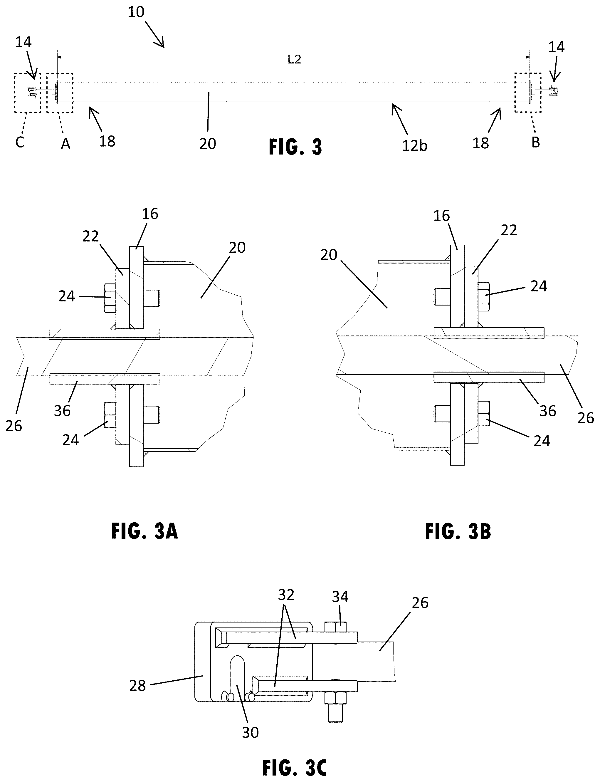
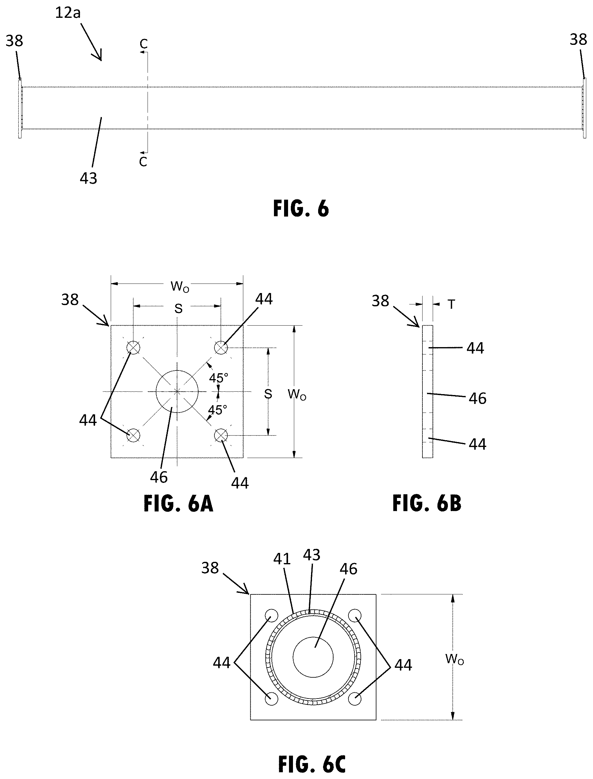
[0043] A modular pipe brace assembly 10, such as shown in FIG. 2, provides various length and load capacity solutions for temporarily supporting several differently sized, shaped, weighted, and types of concrete wall panels in an upright or vertical orientation. To provide the various lengths, generally at least two brace sections are attached together in longitudinal alignment by engaging the adjoining ends of the brace sections to define a pipe assembly with a desired length. The brace sections are attached in a removable manner, such as with removable bolts, so that the brace sections may be reassembled in a different configuration, such as with another one of the brace sections, to provide a different pipe assembly for a different use. Also, for shorter bracing lengths, a single brace section may be utilized. To reduce the inventory levels associated with traditional wall braces, the modular pipe brace assembly 10 may include at least one standard length brace section that has a commonly used bracing length. As shown in FIG. 2, the modular pipe brace assembly 10 includes two different brace sections 12a, 12b that each have a standard length L1 and L2. As illustrated in FIG. 2, the first standard length L1 is a 10 foot brace section 12a and the second standard length L2 is a 40 foot brace section 12b. In additional examples, the standard lengths may vary, such as 20, 30, or 60 foot brace sections.
[0044] As shown in FIG. 2, assembling the exemplary standard length brace sections 12a, 12b with shoe assemblies 14 at each end provides a 50 foot pipe assembly (with a total length of 52 feet when considering the shoe assemblies 14), a 60 foot pipe assembly (with a total length of 62 feet when considering the shoe assemblies 14), and a 80 foot pipe assembly (with a total length of 82 feet when considering the shoe assemblies 14). It is also contemplated that any of the pipe assemblies shown in FIG. 2 may be extended by adding one or two of the shorter brace sections to the ends, so as to provide 70 or 90 foot pipe assemblies. The longer, 40 foot brace sections 12b may also be used individually on a pipe brace, as also shown in FIG. 2, and the shorter 10 foot pipe sections 12a may also be used individually or attached together for shorter bracing lengths, such as for pipe assemblies with desired 10, 20, or 30 foot spans. It is contemplated that different standard lengths may be provided from those illustrated, and it is understood that more than one or two standard lengths of brace sections may be used with the pipe brace assembly.
[0045] The standard length brace sections 12a, 12b may be assembled to provide the desired overall bracing length, while also providing the needed increased load capacity for longer brace extensions. For example, the longer standard length brace sections 12b may include a higher load capacity than shorter standard length brace sections 12a, as there are often higher load requirements when the elevation of the bracing locations increases. Also, as the overall length of a wall brace increases, the central portion of the wall brace often has the highest loading requirement or bending strength requirement along the length of the wall brace. Thus, the modular pipe brace assembly 10 may provide brace sections that each have a pipe with one of at least two load capacities, where the high-load brace section 12b may have a longer length than the standard length of the low-load brace section 12a and where the high-load brace section 12b is disposed at the central portion of the bracing length.
[0046] The pipe assembly or single pipe sections may engage with the wall panel and the floor or ground anchor by using a shoe assembly that is attached to each end of the pipe assembly. As shown in FIG. 2, the shoe assemblies 14 may add to the overall length of the modular pipe brace assembly 10, such as to add a foot to each end of the pipe assembly and provide the exemplary illustrated overall lengths of 42 feet, 52 feet, 62 feet, and 82 feet (not illustrated to scale). The shoe assemblies 14 may also have an adjustable length from approximately negligible or 1 inch of extension beyond the end of the pipe assembly to approximately 32 inches or 30 to 35 inches of extension beyond the end of the pipe assembly. It is understood that additional examples of the shoe assemblies may be configured to extend further that the ranges described herein.
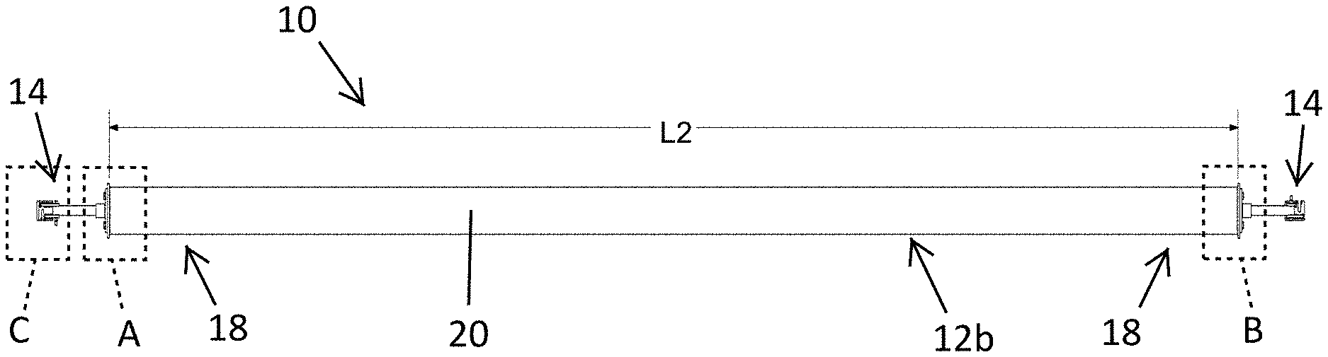
[0047] As shown in FIG. 3, the pipe brace assembly 10 provides a single brace section 12b that is approximately 40 feet long and has shoe assemblies 14 attached to opposing ends of the brace section 12b. To facilitate engagement of the brace section to the shoe assemblies 14, the brace section 12b has a connection plate 16 that is attached to the opposing ends 18 of a pipe 20 that extends along the substantial entire length of the brace section 12b. The connection plate 16 is attached to the end of the pipe 20 in generally perpendicular planar alignment relative to the length of the pipe 20. The shoe assembly 14 has a mounting plate 22 that is removably attached to and against the connection plate 16 of the brace section 12b, such as with the bolts 24 shown in FIGS. 3A-3B that extend through the mounting plate 22 and the connection plate 16 to dispose the ends of the bolts 24 within a hollow interior of the pipe 20 of the brace section 12b. The bolts 24 hold the shoe assembly 14 to the brace section 12b by threadably engaging threads formed in holes 25 that extend through the connection plate 16. It is also contemplated that in other example that welded nuts or other conceivable thread connectors may be provided on the connection plate to engage bolts.
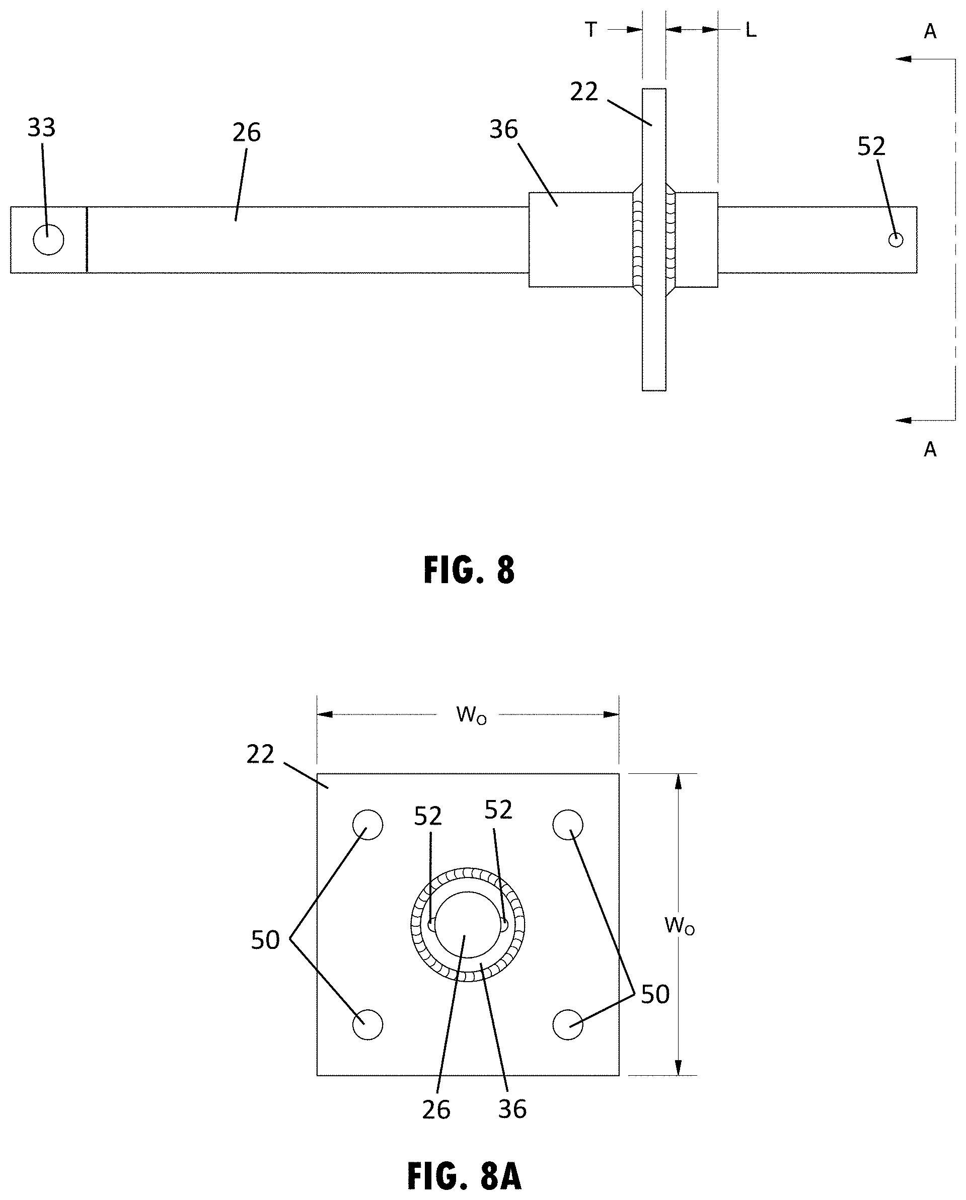
[0048] The shoe assembly 14 may also have a threaded rod 26 and a shoe 28 pivotally attached to an end of the rod 26, such as shown in FIG. 3C. The shoe 28 shown in FIG. 3C has a slot 30 in the base of the shoe 28 for engaging a post, fastener, or other protrusion extending from or part of a ground anchor or slab anchor. Also, the shoe 28 may have arms 32 that extend from the base at a spacing from each other to receive the end of the threaded rod 26 between the arms 32. To provide pivotal motion of the shoe 28 relative to the threaded rod 26, a fastener, such as a bolt 34 as shown in FIG. 3C, may connect between the arms 32 and extend through a transverse hole 33 (FIG. 8) formed in the end of the rod 26 that is disposed transverse to the length of the rod 26.
[0049] As also shown in FIGS. 3A and 3B, the threaded rod 26 operably engages the mounting plate 22 by extending though a threaded central aperture disposing within a barrel 36 that is fixed to the mounting plate 22 of the shoe assembly 14 at a central and longitudinally disposed location relative to the pipe 20. The threaded rod 26 is permitted to rotate and cause longitudinal translation or displacement of the shoe 28 relative to the brace section 12b by rotation of the threaded rod 26 relative to the mounting plate 22. As such, the effective length of the shoe assemblies 14 may be adjusted, such as to adjust the length from approximately negligible or 1 inch of extension beyond the end of the pipe assembly to approximately 32 inches or 30 to 35 inches of extension beyond the end of the pipe assembly. The range of adjustability of the shoe assembly is based, at least in part, on the strength and diameter of the rod 26 and the threaded engagement with the mounting plate 22, such that it is contemplated that the range of adjustability may be greater or less than 35 inches in other examples of the shoe assembly.
[0050] As shown in FIGS. 4-4B, the pipe brace assembly 10 provides two different brace sections 12a, 12b attached to each other in longitudinal alignment by engaging the connection plate 16 of the 40 foot brace section 12b with the connection plate 38 of the shorter, 10 foot brace section 12a. When the central axes of the brace sections are aligned and the ends are abutting, the brace sections 12a, 12b, such as shown in FIG. 4B, are temporarily attached together with bolts 24 that extend through an outer flange of the smaller connection plate 38 and into the threaded holes 25 (FIG. 7A) of the larger connection plate 16. Although temporary, the bolted attachment of brace sections provides a rigid and stable connection for the pipe assembly. At the end of the pipe assembly provided by the end of the shorter, 10 foot brace section 12a, a shoe assembly 14 may be attached to the outer flange of the smaller connection plate 38, such as shown in FIG. 4A with bolts 24 and nuts 40 that clamp the mounting plate 22 of the shoe assembly 14 to the connection plate 38 of the brace section 12a. It is contemplated that the smaller connection plate of a shorter brace section in other examples may include threaded holes similar to those provided in the larger connection plate 16 shown in FIG. 4B.
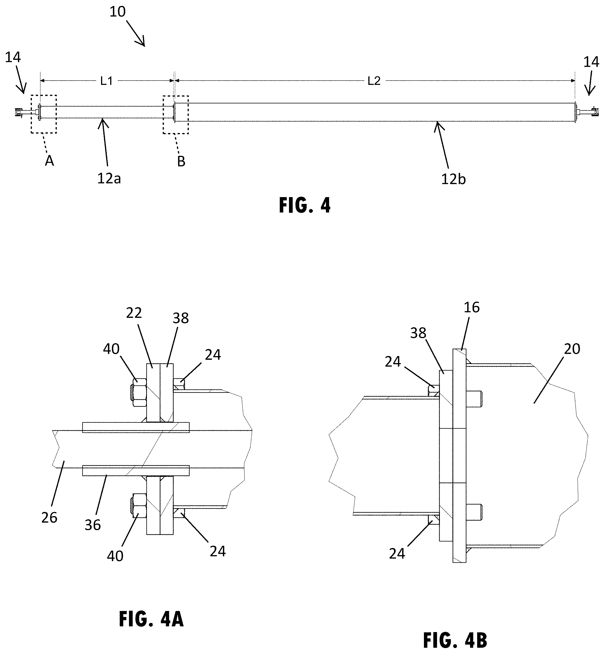
[0051] Furthermore, as shown in FIG. 5, the pipe brace assembly 10 provides the use of two longer brace sections 12b disposed in longitudinal alignment and attached to each other, so as to provide an 80 foot pipe assembly. The brace sections 12b are temporarily or removably attached together when the central axes of the brace sections 12b are aligned by engaging the connection plates 16 together by using a second set of holes 42 in the connection plate 16 (FIG. 7A) that extend through the outer flange of the connection plates 16 at an outer radial spacing from the threaded holes 25. Thus, to facilitate the assembly of various pipe brace assemblies using different types of brace sections, one of the brace sections, such as the longer standard length or higher-load capacity brace sections 12b, may be configured to attach to multiple different brace sections, such as to a shorter brace section 12a (FIG. 4), a longer brace section 12b (FIG. 5), or a shoe assembly 14 (FIG. 3), among other conceivable brace sections.
[0052] As shown in greater detail in FIGS. 6-6C, the pipe brace section 12a has a pipe 43 with a circular transverse cross-sectional shape. The circular cross-sectional shape of the pipe 20 has a diameter of 8 inches, which is larger than the diameter of the pipe of the shorter pipe brace section 12a. The ends of the pipe 43 are cut perpendicular to the length of the pipe 43 and attached via welding to the square-shaped connection plate 38, where the weld 41 is provided around the circumference of the pipe 43. The holes 44 in the connection plate 38 that receive fasteners for securing the pipe brace section 12a to other pipe brace sections or the foot assembly may be formed in the corners of the outer flange of the connection plate 38, such as shown in FIG. 6C outside the circumference of the pipe 43. The connection plate 38 may also include a central hole 46 that can receive the threaded rod 26 of the shoe assembly 14, such as when the threaded rod 26 is retracted to provide the shoe assembly 14 with a shorter or intermediate length, such as shown in FIG. 4A. Accordingly, the multiple holes provided in the connection plate 38 allows shorter pipe brace section 12a to connect to a longer brace section 12b, another shorter brace section 12a, or a shoe assembly 14, among other conceivable brace sections.
[0053] As shown in FIGS. 6A-6C, the dimensions of the exemplary connection plate 38 include an outer width W.sub.O of 8 inches between each of the opposing outer sides to provide a square shape. Also, the thickness T of the connection plate 38 is 0.625 inches. The holes 44 in the connection plate 38 are disposed at an equal distance from the central hole 46 at a 45 degree angle from the liner extent of the outer sides of the connection plate. As a result, the spacing S between the holes 44 is 5.3 inches. It is contemplated that other dimensions and configurations may be provided in additional examples of the connection plate.
[0054] The longer pipe brace section 12b, as shown in greater detail in FIGS. 7-7C, also includes a pipe 20 that has a circular transverse cross-sectional shape and a larger diameter than the pipe 43 of the shorter pipe brace section 12a so as to provide a higher load capacity. Such a higher load capacity may also be provided with an increase in the gauge of the pipe wall or with the type of material used, such as a higher strength steel (e.g., advanced high strength steel) or aluminum alloy. The ends of the pipe 20 are cut perpendicular to the length of the pipe 20 and attached via welding to the square-shaped connection plate 16, where the weld is provided around the circumference of the pipe 20. The connection plate 16 has two sets of peripheral holes 25, 42 that receive fasteners for securing the pipe brace section 12b to other pipe brace sections or the foot assembly. The outer holes 42 formed in the corners of the outer flange of the connection plate 16, such as shown in FIG. 6C, are provided radially outside the circumference of the pipe 20 to engage another one of the longer pipe brace sections 12b (FIG. 5A). The connection plate 16 also includes inner holes 25 inside the circumference of the pipe 20 that may threadably engage bolts 24 that attach the smaller pipe brace section 12a (FIG. 4B) or the shoe assembly 14 (FIGS. 3A and 3B). Further, similar to the smaller connection plate 48, a central hole 46 may be provided in the connection plate, as shown in FIGS. 7A-7C that may receive the threaded rod of the shoe assembly, such as when the threaded rod is retracted to provide the shoe assembly with a shorter or intermediate length (FIG. 3A). Accordingly, the multiple types of holes provided in the connection plate 16 allows the longer pipe brace section 12b to connect to a shorter brace section 12a, another longer brace section 12b, or a shoe assembly 14, among other conceivable brace sections.
[0055] As shown in FIGS. 7A-7C, the dimensions of the exemplary connection plate 16 include an outer width W.sub.O of 10 inches between each of the opposing outer sides to provide a square shape. Also, the thickness T of the connection plate 38 is 0.625 inches. The holes 25, 42 in the connection plate 38 are each disposed at a distance from the central hole 46 at a 45 degree angle from the liner extent of the outer sides of the connection plate. As a result, the spacing S.sub.O between the outer holes 42 is 8 inches and the space Si between the inner holes 25 is 5.3 inches. Again, it is contemplated that other dimensions and configurations may be provided in additional examples of the connection plate.
[0056] As shown again in FIGS. 8 and 8A, the shoe assembly 14 is provided with the threaded rod 26 that is operably engaged with the mounting plate 22 by extending though a threaded barrel 36 that is fixed to the mounting plate 22. The mounting plate 22 has a square shape in this illustrated example (FIG. 8A) and has holes 50 that are configured to align with the holes 44 (FIG. 6A) in the connection plate 38 of the shorter brace section 12a and the inner holes 25 (FIG. 7A) on the connection plate 16 of the longer brace section 12b. As also shown in FIG. 8, the end of the threaded rod 26 that engages the shoe 28 (FIG. 3C) has a transverse hole 33 for receiving the fastener that engages the shoe 28. The other end of the threaded rod 26 includes a lateral protrusions 52 that act as a stop to limit the extendable length of the shoe assembly 14, as extending beyond the protrusions 52 would disengage the threaded rod 26 from the mounting plate 22. Thus, to adjust the length of the shoe assemblies 14, the threaded rod 26 is permitted to rotate relative to the mounting plate 22 to longitudinally displace or translate the shoe relative to the corresponding pipe assembly.
[0057] As further shown in FIGS. 8 and 8A, the dimensions of the mounting plate 22 of the exemplary shoe assembly 14 include an outer width W.sub.O of 8 inches between each of the opposing outer sides to provide a square shape. Also, the thickness T of the mounting plate 22 is 0.625 inches. The length L of the inner portion of the threaded barrel 36 that extends into the engaged pipe extension is 1.375 inches. Again, it is contemplated that other dimensions and configurations may be provided in additional examples of the shoe assembly.
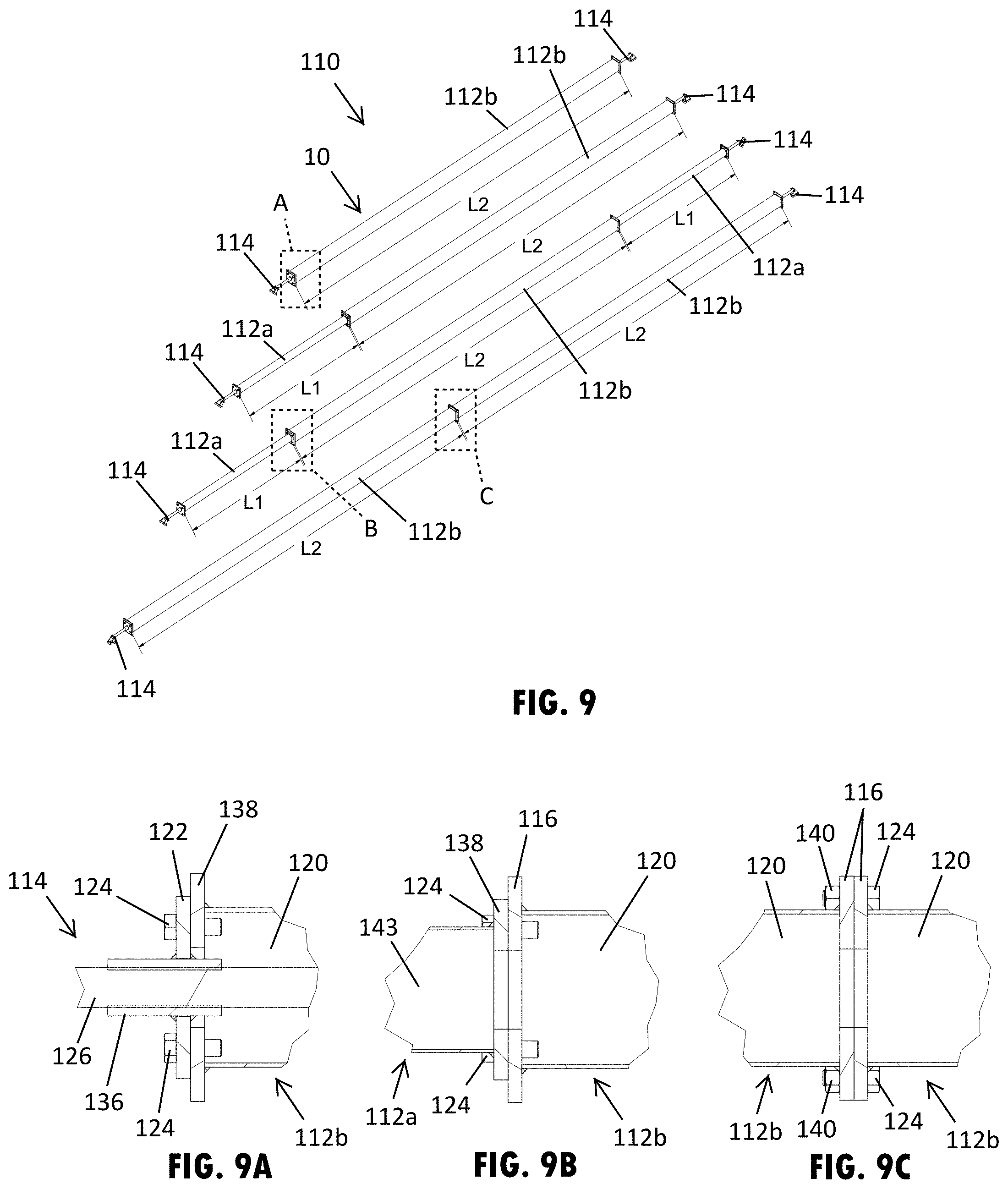
[0058] Referring now to FIGS. 9-10A, another example of the pipe brace assembly 110 also provides various length and load capacity solutions for temporarily supporting several differently sized, shaped, weighted, and types of concrete wall panels in an upright or vertical orientation. The pipe brace assembly 110 is substantially similar to the example shown in FIG. 2, as the modular pipe brace assembly 110 includes two different brace sections 112a, 112b that each have a standard length L1 and L2. As illustrated in FIG. 10, the first standard length L1 is a 10 foot brace section 112a and the second standard length L2 is a 40 foot brace section 112b. In additional examples, the standard lengths may vary, such as 20, 30, or 60 foot brace sections.
[0059] As shown in FIG. 9, assembling the exemplary standard length brace sections 112a, 112b with shoe assemblies 114 at each end provides a 50 foot pipe assembly (with a total length of 52 feet when considering the shoe assemblies 114), a 60 foot pipe assembly (with a total length of 62 feet when considering the shoe assemblies 114), and a 80 foot pipe assembly (with a total length of 82 feet when considering the shoe assemblies 114). However, different from the exemplary brace section 12b shown in FIG. 7, the longer pipe brace section 112b, as shown in greater detail in FIGS. 10 and 10A, includes a pipe 120 that has a square transverse cross-sectional shape. The square cross-sectional shape of the pipe 120 has a diameter of 7 inches parallel to the sides of the pipe 120, which is larger than the diameter of the pipe of the shorter pipe brace section 112a.
[0060] As shown in FIGS. 10 and 10A, the ends of the square pipe 120 are cut perpendicular to the length of the square pipe 120 and attached via welding to the square-shaped connection plate 116, where the weld 141 is provided substantially around the circumference of the pipe 120. The connection plate 116 has two sets of outer peripheral holes 142, 125 that receive fasteners for securing the pipe brace section 112b to other pipe brace sections (FIGS. 9B and 9C) or the foot assembly 114 (FIG. 9A). Further, a central hole 146 is shown in the connection plate 116 that may receive the threaded rod of the shoe assembly 114, such as when the threaded rod is retracted to provide the shoe assembly with a shorter or intermediate length (FIG. 9A).
[0061] As further shown in FIGS. 10 and 10A, the dimensions of the exemplary connection plate 116 include an outer width W.sub.O of 10 inches between each of the opposing outer sides to provide a square shape. Also, the thickness T of the connection plate 116 is 1.25 inches. The holes 125, 142 in the connection plate 116 are each disposed at a distance from the central hole 146 at a 45 degree angle from the liner extent of the outer sides of the connection plate, such as to be disposed inside and outside the corners of the pipe 120. Again, it is contemplated that other dimensions and configurations may be provided in additional examples of the connection plate.
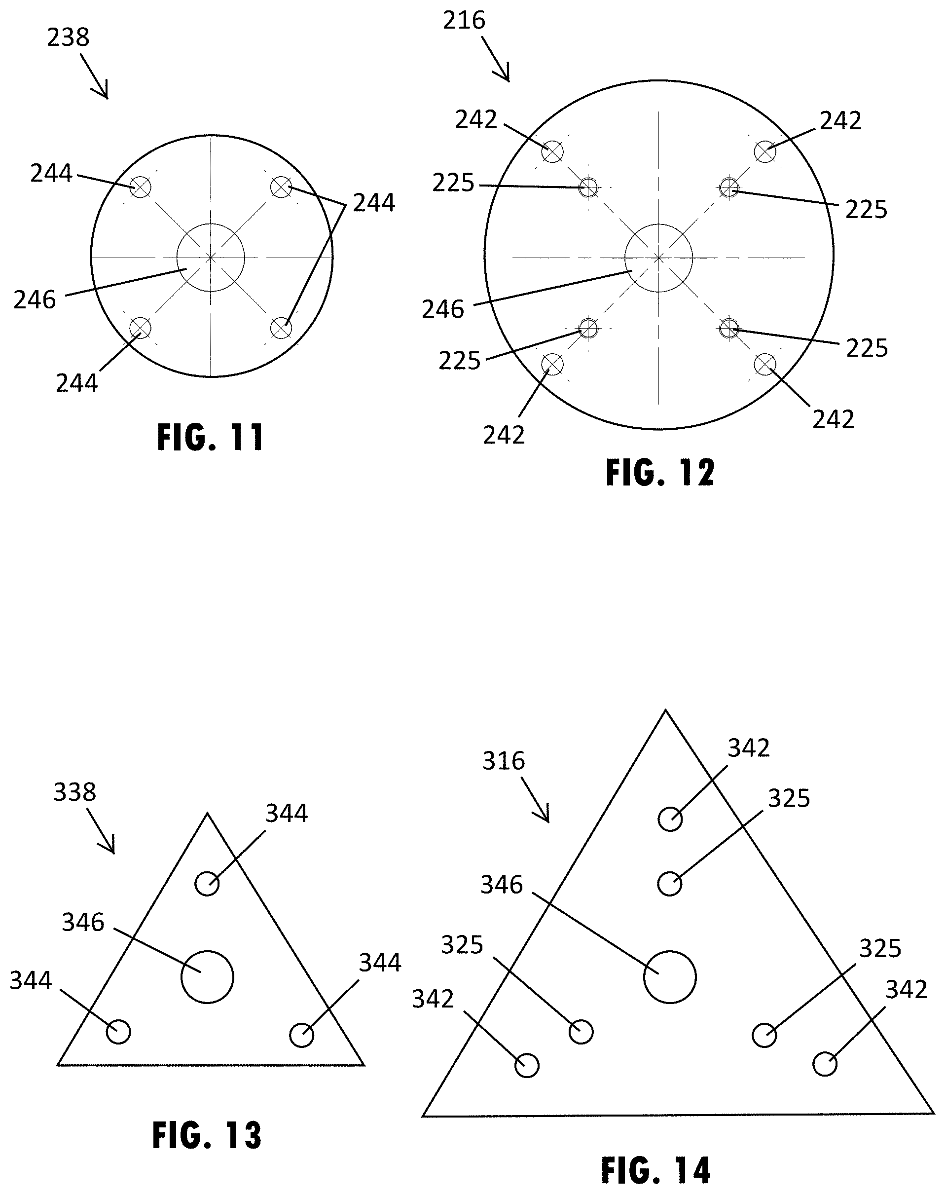
[0062] Furthermore, one or more of the mounting and connection plates used with a modular pipe brace assembly may also have a different shape from those shown in FIGS. 2-10A, such as the additional exemplary shapes shown in FIGS. 11-14. Specifically, FIGS. 11 and 12 show a circular shaped, smaller connection plate 238 for a shorter brace section and a circular shaped, larger connection plate 216 for a longer brace section. Similar to the examples shown and described above, the connection plates 238, 216 have multiple holes for temporarily attaching to different brace sections or foot assemblies. The smaller connection plate 238 has four perimeter holes 244 that are disposed at the outer flange of the corresponding brace section, such that fasteners that engage the holes 244 are disposed outside the hollow interior of the pipe of the corresponding brace section. The larger connection plate 216 has two sets of outer peripheral holes 242, 225 that receive fasteners for securing the pipe brace section to other pipe brace sections or the foot assembly. Further, a central hole 246 is shown in each connection plate 238, 216 that may receive the threaded rod of a shoe assembly, such as when the threaded rod is retracted to provide the shoe assembly with a shorter or intermediate length. Since the holes in the connection plates 238, 216 shown in FIGS. 11 and 12 are located at the same or substantially similar positions to the connection plates shown in the embodiments above, these connection plates 238, 216 may be attached to the other illustrated connection plates 38, 16, 138, 116.
[0063] Also, FIGS. 13 and 14 show triangular shaped connection plates that may be integrated with the modular pipe brace assembly. As shown in FIG. 13, a smaller connection plate 338 is provided for a shorter brace section and a larger connection plate 316 is provided for a longer brace section. Again, similar to the examples shown and described above, the connection plates 338, 316 have multiple holes for temporarily attaching to different brace sections or foot assemblies. However, the smaller connection plate 338 has three perimeter holes that are disposed at the outer flange of the corresponding brace section, such that fasteners that engage the holes are disposed outside the hollow interior of the pipe of the corresponding brace section. The connection plate 316 has two sets of outer peripheral holes 342, 325 that each have three holes for receiving fasteners for securing the pipe brace section to other pipe brace sections or the foot assembly. Further, a central hole 346 is shown in each connection plate 338, 316 that may receive the threaded rod of a shoe assembly, such as when the threaded rod is retracted to provide the shoe assembly with a shorter or intermediate length.
[0064] The modular pipe brace assembly disclosed herein may be used with multiple and various types of construction projects and applications by assembling the different brace sections in desired bracing lengths. The cross-sectional geometry, material type selections, and material thickness within the cross-sectional profile of the components of the pipe brace assembly may be configured for such a particular use and the desired loading and performance characteristics of the pipe brace assembly as generally understood.
[0065] For purposes of this disclosure, the terms "upper," "lower," "right," "left," "rear," "front," "vertical," "horizontal," "inner," "outer," "inner-facing," "outer-facing," and derivatives thereof shall relate to the pipe assemblies as oriented in FIG. 1. However, it is to be understood that the invention may assume various alternative orientations, except where expressly specified to the contrary. It is also to be understood that the specific devices and processes illustrated in the attached drawings, and described in this specification are simply exemplary embodiments of the inventive concepts defined in the appended claims. Hence, specific dimensions and other physical characteristics relating to the embodiments disclosed herein are not to be considered as limiting, unless the claims expressly state otherwise.
[0066] Changes and modifications in the specifically described embodiments may be carried out without departing from the principles of the present invention, which is intended to be limited only by the scope of the appended claims as interpreted according to the principles of patent law. The disclosure has been described in an illustrative manner, and it is to be understood that the terminology which has been used is intended to be in the nature of words of description rather than of limitation. Many modifications and variations of the present disclosure are possible in light of the above teachings, and the disclosure may be practiced otherwise than as specifically described.
* * * * *
D00000
D00001
D00002
D00003
D00004
D00005
D00006
D00007
D00008
D00009
D00010
XML
uspto.report is an independent third-party trademark research tool that is not affiliated, endorsed, or sponsored by the United States Patent and Trademark Office (USPTO) or any other governmental organization. The information provided by uspto.report is based on publicly available data at the time of writing and is intended for informational purposes only.
While we strive to provide accurate and up-to-date information, we do not guarantee the accuracy, completeness, reliability, or suitability of the information displayed on this site. The use of this site is at your own risk. Any reliance you place on such information is therefore strictly at your own risk.
All official trademark data, including owner information, should be verified by visiting the official USPTO website at www.uspto.gov. This site is not intended to replace professional legal advice and should not be used as a substitute for consulting with a legal professional who is knowledgeable about trademark law.