Shovel And Shovel Management System
NISHI; Takashi
U.S. patent application number 16/941924 was filed with the patent office on 2020-11-12 for shovel and shovel management system. The applicant listed for this patent is SUMITOMO CONSTRUCTION MACHINERY CO., LTD.. Invention is credited to Takashi NISHI.
| Application Number | 20200354921 16/941924 |
| Document ID | / |
| Family ID | 1000005015827 |
| Filed Date | 2020-11-12 |


View All Diagrams
| United States Patent Application | 20200354921 |
| Kind Code | A1 |
| NISHI; Takashi | November 12, 2020 |
SHOVEL AND SHOVEL MANAGEMENT SYSTEM
Abstract
A shovel includes a lower traveling body, an upper turning body turnably mounted on the lower traveling body, an attachment attached to the upper turning body, and a hardware processor on the upper turning body and configured to execute automatic control. The hardware processor is configured to stop the automatic control when information on the movement of the shovel or information on the state of a nearby machine shows an unusual tendency.
| Inventors: | NISHI; Takashi; (Chiba, JP) | ||||||||||
| Applicant: |
|
||||||||||
|---|---|---|---|---|---|---|---|---|---|---|---|
| Family ID: | 1000005015827 | ||||||||||
| Appl. No.: | 16/941924 | ||||||||||
| Filed: | July 29, 2020 |
Related U.S. Patent Documents
| Application Number | Filing Date | Patent Number | ||
|---|---|---|---|---|
| PCT/JP2019/003201 | Jan 30, 2019 | |||
| 16941924 | ||||
| Current U.S. Class: | 1/1 |
| Current CPC Class: | E02F 3/32 20130101; E02F 3/439 20130101; E02F 9/2285 20130101; E02F 9/123 20130101; E02F 9/2004 20130101 |
| International Class: | E02F 3/43 20060101 E02F003/43; E02F 3/32 20060101 E02F003/32; E02F 9/12 20060101 E02F009/12; E02F 9/22 20060101 E02F009/22; E02F 9/20 20060101 E02F009/20 |
Foreign Application Data
| Date | Code | Application Number |
|---|---|---|
| Jan 30, 2018 | JP | 2018-013970 |
Claims
1. A shovel comprising: a lower traveling body; an upper turning body turnably mounted on the lower traveling body; an attachment attached to the upper turning body; and a hardware processor on the upper turning body and configured to execute automatic control, wherein the hardware processor is configured to stop the automatic control when information on a movement of the shovel or information on a state of a nearby machine shows an unusual tendency.
2. The shovel as claimed in claim 1, wherein the information on the movement of the shovel is information on an operation of an operating apparatus mounted on the upper turning body, and the hardware processor is further configured to determine that the information on the movement of the shovel shows the unusual tendency when the operating apparatus is rapidly operated.
3. The shovel as claimed in claim 1, wherein the automatic control is automatic straight facing control or automatic complex turning control, the information on the movement of the shovel is information on an operation of an operating apparatus mounted on the upper turning body, and the hardware processor is configured to determine that the information on the movement of the shovel shows the unusual tendency when an operation to turn the upper turning body in a direction opposite to a direction of turning performed by the automatic control.
4. The shovel as claimed in claim 1, further comprising: a switch related to the automatic control, wherein the hardware processor is further configured to execute the automatic control when the switch is operated.
5. The shovel as claimed in claim 1, wherein the automatic control is control to move a working part along an intended trajectory.
6. The shovel as claimed in claim 5, wherein the intended trajectory is generated based on an output of a space recognition device.
7. The shovel as claimed in claim 1, wherein a first operation signal output by an operating signal generating part of an operating lever is input to the hardware processor, and a second operation signal is output to a solenoid valve controlling a pilot pressure of a control valve, based on the input first operation signal.
8. The shovel as claimed in claim 1, wherein the hardware processor is configured to stop the automatic control when an operator performs an arm opening operation out of reflex or when the operator performs a boom lowering operation out of reflex.
9. A shovel comprising: a lower traveling body; an upper turning body turnably mounted on the lower traveling body; an attachment attached to the upper turning body; a space recognition device attached to the upper turning body; a body tilt sensor configured to detect a tilt of the upper turning body; and a hardware processor on the upper turning body and configured to execute automatic control, wherein the hardware processor is configured to stop the automatic control based on an output of the body tilt sensor or the space recognition device.
10. The shovel as claimed in claim 9, wherein the automatic control is control to move a working part along an intended trajectory.
11. The shovel as claimed in claim 10, wherein the intended trajectory is generated based on the output of the space recognition device.
12. The shovel as claimed in claim 10, wherein the intended trajectory is a trajectory related to a movement of an excavation attachment in work of loading a bed of a dump truck with soil.
13. The shovel as claimed in claim 9, wherein a first operation signal output by an operating signal generating part of an operating lever is input to the hardware processor, and a second operation signal is output to a solenoid valve controlling a pilot pressure of a control valve, based on the input first operation signal.
14. The shovel as claimed in claim 9, wherein the hardware processor is configured to stop the automatic control when an operator performs an arm opening operation out of reflex or when the operator performs a boom lowering operation out of reflex.
15. The shovel as claimed in claim 9, wherein the hardware processor is configured to perform feedback control based on a turning angle.
16. A shovel management system comprising: a shovel configured to store at least one of a time of a stoppage of automatic control executed by the shovel, a location of the stoppage, an attitude of the shovel at the time of the stoppage, and a peripheral image at the time of the stoppage, and transmit the stored at least one of the time, the location, the attitude, and the peripheral image; and a management apparatus configured to receive the at least one of the time, the location, the attitude, and the peripheral image, and output at least one of the received attitude and peripheral image when the management apparatus receives the at least one of the attitude and the peripheral image.
Description
CROSS-REFERENCE TO RELATED APPLICATIONS
[0001] This application is a continuation application filed under 35 U.S.C. 111(a) claiming benefit under 35 U.S.C. 120 and 365(c) of PCT International Application No. PCT/JP2019/003201, filed on Jan. 30, 2019 and designating the U.S., which claims priority to Japanese patent application No. 2018-013970, filed on Jan. 30, 2018. The entire contents of the foregoing applications are incorporated herein by reference.
BACKGROUND
Technical Field
[0002] The present disclosure relates to shovels and shovel management systems.
Description of Related Art
[0003] An excavator that enables selective use of a manual control mode and an automatic control mode has been known, where the manual control mode causes only an arm to operate in response to the operation of an aim operating lever and the automatic control mode causes not only the arm but also a boom and a bucket to operate in response to the operation of the arm operating lever. This excavator can automatically move the attachment such that the bucket moves along an inclined surface having a preset inclination angle in the automatic control mode. Specifically, this excavator can move the leading edge of the bucket in a straight line by automatically operating the boom and the bucket in response to the operation of the arm operating lever.
SUMMARY
[0004] According to an aspect of the present invention, a shovel includes a lower traveling body, an upper turning body turnably mounted on the lower traveling body, an attachment attached to the upper turning body, and a hardware processor on the upper turning body and configured to execute automatic control. The hardware processor is configured to stop the automatic control when information on the movement of the shovel or information on the state of a nearby machine shows an unusual tendency.
BRIEF DESCRIPTION OF THE DRAWINGS
[0005] FIG. 1 is a side view of a shovel according to an embodiment of the present invention;
[0006] FIG. 2 is a diagram illustrating an example configuration of the basic system of the shovel of FIG. 1;
[0007] FIG. 3 is a diagram illustrating an example configuration of a hydraulic system installed in the shovel of FIG. 1;
[0008] FIG. 4 is a block diagram illustrating an example of the relationship between functional elements associated with the execution of automatic control in a controller;
[0009] FIG. 5 is a block diagram illustrating an example configuration of the functional element that calculates various command values;
[0010] FIG. 6 is a diagram illustrating the state of the hydraulic system when an arm opening operation has been performed during automatic excavation control in the shovel where an emergency stop function is disabled;
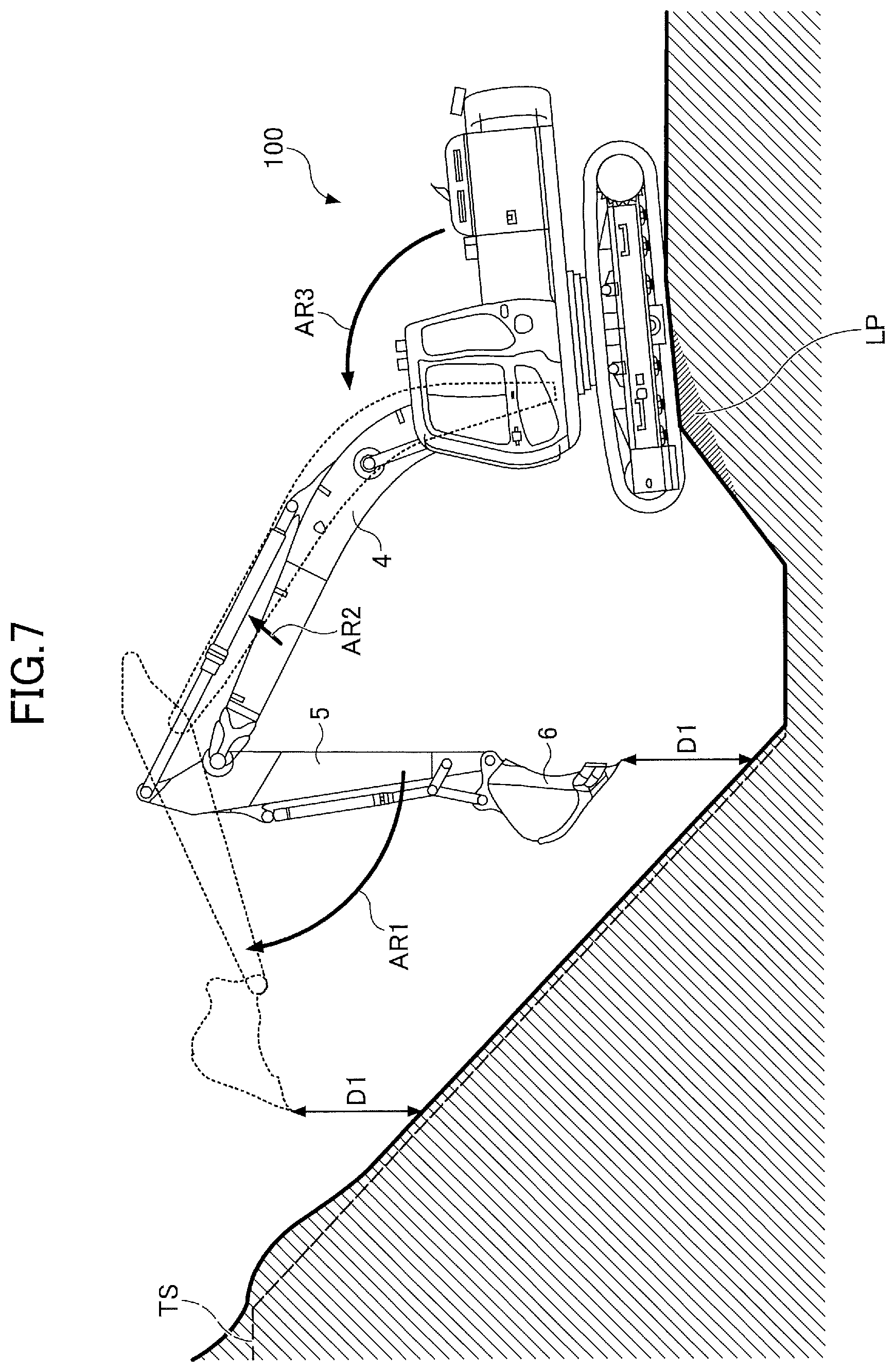
[0011] FIG. 7 is a diagram illustrating the movement of an excavation attachment when an arm opening operation has been performed during the automatic excavation control in the shovel where the emergency stop function is disabled;
[0012] FIG. 8 is a diagram illustrating the state of the hydraulic system when an aim opening operation has been performed during the automatic excavation control in the shovel where the emergency stop function is enabled;
[0013] FIG. 9 is a diagram illustrating the movement of the excavation attachment when an aim opening operation has been performed during the automatic excavation control in the shovel where the emergency stop function is enabled;
[0014] FIG. 10 is a diagram illustrating the state of the hydraulic system when a bool lowering operation has been performed during the automatic excavation control in the shovel where the emergency stop function is enabled;
[0015] FIG. 11 is a diagram illustrating the movement of the excavation attachment when a boom lowering operation has been performed during the automatic excavation control in the shovel where the emergency stop function is enabled;
[0016] FIG. 12 is a block diagram illustrating another example of the relationship between the functional elements associated with the execution of automatic control in the controller;
[0017] FIG. 13 is a block diagram illustrating another example configuration of the functional element that calculates various command values;
[0018] FIG. 14 is a plan view of a work site, illustrating the movement of the excavation attachment when a turning operation is performed during automatic complex turning control;
[0019] FIG. 15 is a diagram illustrating the movement of the excavation attachment when a counterclockwise turning operation is performed during the clockwise turning of an upper turning body in the shovel where the emergency stop function is enabled;
[0020] FIG. 16 is a diagram illustrating an example configuration of an electric operation system; and
[0021] FIG. 17 is a schematic diagram illustrating an example configuration of a shovel management system.
DETAILED DESCRIPTION
[0022] Normally, the excavator is used in various operating environments. Therefore, the operating environment around the excavator may change to an operating environment different from the expected operating environment even when the automatic control mode is in operation. In this case, the above-described excavator continues operation in the automatic control mode even when the operating environment changes. For example, when the operator operates the arm operating lever with the intention to open the arm to press the bucket against an upward inclined surface in an emergency during the automatic control mode, the excavator may automatically raise the boom in accordance with the opening of the arm to move the bucket along the upward inclined surface. In this case, the operator may be unable to press the bucket against the upward inclined surface as intended.
[0023] Therefore, even during automatic control, it is desirable to cause a shovel to perform operation different from the operation of the automatic control when the operating environment of the shovel changes to an operating environment different from the expected operating environment.
[0024] According to an aspect of the present invention, it is possible to cause a shovel to perform operation different from the operation of automatic control when the operating environment of the shovel changes to an operating environment different from the expected operating environment even during the automatic control.
[0025] FIG. 1 is a side view of a shovel 100 serving as an excavator according to an embodiment of the present invention. An upper turning body 3 is turnably mounted on a lower traveling body 1 of the shovel 100 via a turning mechanism 2. A boom 4 is attached to the upper turning body 3. An arm 5 is attached to the distal end of the boom 4, and a bucket 6 serving as an end attachment is attached to the distal end of the arm 5.
[0026] The boom 4, the arm 5, and the bucket 6 form an excavation attachment that is an example of an attachment. The boom 4 is driven by a boom cylinder 7, the arm 5 is driven by an arm cylinder 8, and the bucket 6 is driven by a bucket cylinder 9.
[0027] Specifically, the boom cylinder 7 is driven in response to tilting of a boom operating lever, the arm cylinder 8 is driven in response to tilting of an arm operating lever, and the bucket cylinder 9 is driven in response to tilting of a bucket operating lever. Likewise, a right side traveling hydraulic motor 1R (see FIG. 2) is driven in response to tilting of a right side travel lever, a left side traveling hydraulic motor 1L (see FIG. 2) is driven in response to tilting of a left travel lever, and a turning hydraulic motor 2A (see FIG. 2) is driven in response to tilting of a turning operating lever. Thus, a corresponding actuator is driven in response to the operation of each lever, so that control of the shovel 100 through an operator's manual operation (hereinafter "manual control") is performed.
[0028] Furthermore, a boom angle sensor S1 is attached to the boom 4, an arm angle sensor S2 is attached to the arm 5, and a bucket angle sensor S3 is attached to the bucket 6.
[0029] The boom angle sensor S1 is configured to detect the rotation angle of the boom 4. According to this embodiment, the boom angle sensor S1 is an acceleration sensor and can detect the rotation angle of the boom 4 relative to the upper turning body 3 (hereinafter, "boom angle"). For example, the boom angle is smallest when the boom 4 is lowest and increases as the boom 4 is raised.
[0030] The arm angle sensor S2 is configured to detect the rotation angle of the arm 5. According to this embodiment, the arm angle sensor S2 is an acceleration sensor and can detect the rotation angle of the arm 5 relative to the boom 4 (hereinafter, "arm angle"). For example, the arm angle is smallest when the arm 5 is most closed and increases as the arm 5 is opened.
[0031] The bucket angle sensor S3 is configured to detect the rotation angle of the bucket 6. According to this embodiment, the bucket angle sensor S3 is an acceleration sensor and can detect the rotation angle of the bucket 6 relative to the arm 5 (hereinafter, "bucket angle"). For example, the bucket angle is smallest when the bucket 6 is most closed and increases as the bucket 6 is opened.
[0032] Each of the boom angle sensor S1, the arm angle sensor S2, and the bucket angle sensor S3 may alternatively be a potentiometer using a variable resistor, a stroke sensor that detects the stroke amount of a corresponding hydraulic cylinder, a rotary encoder that detects a rotation angle about a link pin, an inertial measurement unit, a gyroscope, a combination of an acceleration sensor and a gyroscope, or the like.
[0033] A cabin 10 that is a cab is provided and a power source such as an engine 11 is mounted on the upper turning body 3. A controller 30, a display device 40, an input device 42, an audio output device 43, a storage device 47, an emergency stop switch 48, a body tilt sensor S4, a turning angular velocity sensor S5, an image capturing device S6, a communications device T1, and a positioning device P1 are attached to the upper turning body 3.
[0034] The controller 30 is configured to operate as a control device to control the driving of the shovel 100. According to this embodiment, the controller 30 is constituted of a computer including a CPU, a RAM, a ROM, etc. Various functions provided by the controller 30 are implemented by the CPU executing programs stored in the ROM, for example. The various functions include, for example, a machine guidance function to guide (give directions to) an operator in manually operating the shovel 100 and a machine control function to automatically assist the operator in manually operating the shovel 100. A machine guidance device 50 included in the controller 30 is configured to be able to execute the machine guidance function and the machine control function.
[0035] The display device 40 is configured to display various kinds of information. The display device 40 may be connected to the controller 30 via a communications network such as a CAN or may be connected to the controller 30 via a dedicated line.
[0036] The input device 42 is so configured as to enable the operator to input various kinds of information to the controller 30. The input device 42 includes, for example, at least one of a touchscreen, a knob switch, a membrane switch, etc., provided in the cabin 10.
[0037] The audio output device 43 is configured to output audio information. The audio output device 43 may be, for example, an in-vehicle loudspeaker connected to the controller 30 or an alarm such as a buzzer. According to this embodiment, the audio output device 43 outputs various kinds of audio information in response to a command from the controller 30.
[0038] The storage device 47 is configured to store various kinds of information. Examples of the storage device 47 include a nonvolatile storage medium such as a semiconductor memory. The storage device 47 may store the output information of various devices while the shovel 100 is in operation and may store information obtained through various devices before the shovel 100 starts to operate. The storage device 47 may store, for example, data on an intended work surface obtained through the communications device T1, etc. The intended work surface may be set by the operator of the shovel 100 or may be set by a work manager or the like. The emergency stop switch 48 is configured to operate as a switch for stopping the movement of the shovel 100. The emergency stop switch 48 is, for example, a switch installed at such a position as to be operable by the operator seated in an operator seat in the cabin 10. According to this embodiment, the emergency stop switch 48 is a foot switch installed at the operator's feet in the cabin 10. When operated by the operator, the emergency stop switch 48 outputs a command to an engine control unit to stop the engine 11. The emergency stop switch 48 may also be a hand switch installed around the operator seat.
[0039] The body tilt sensor S4 is configured to detect the inclination of the upper turning body 3. According to this embodiment, the body tilt sensor S4 is an acceleration sensor that detects the inclination of the upper turning body 3 relative to a virtual horizontal plane. The body tilt sensor S4 may be a combination of an acceleration sensor and a gyroscope or may be an inertial measurement unit or the like. The body tilt sensor S4 detects, for example, the upper turning body 3's tilt angle about its longitudinal axis (roll angle) and tilt angle about its lateral axis (pitch angle). For example, the longitudinal axis and the lateral axis of the upper turning body 3 cross each other at right angles at the shovel center point that is a point on the turning axis of the shovel 100.
[0040] The image capturing device S6 is configured to capture an image of an area surrounding the shovel 100. According to this embodiment, the image capturing device S6 includes a front camera S6F that captures an image of a space in front of the shovel 100, a left camera S6L that captures an image of a space to the left of the shovel 100, a right camera S6R that captures an image of a space to the right of the shovel 100, and a back camera S6B that captures an image of a space behind the shovel 100.
[0041] The image capturing device S6 is, for example, a monocular camera including an imaging device such as a CCD or a CMOS, and outputs captured images to the display device 40. The image capturing device S6 may also be configured to operate as a space recognition device S7. The space recognition device S7 is configured to be able to detect an object present in a three-dimensional space around the shovel 100. The object is, for example, at least one of a person, an animal, a shovel, a machine, a building, etc. The space recognition device S7 may also be configured to be able to calculate the distance between the space recognition device S7 or the shovel 100 and an object detected by the space recognition device S7. The space recognition device S7 may be an ultrasonic sensor, a millimeter wave radar, a monocular camera, a stereo camera, a LIDAR, a distance image sensor, an infrared sensor, or the like.
[0042] The front camera S6F is attached to, for example, the ceiling of the cabin 10, namely, the inside of the cabin 10. The front camera S6F may alternatively be attached to the roof of the cabin 10, namely, the outside of the cabin 10. The left camera S6L is attached to the left end of the upper surface of the upper turning body 3. The right camera S6R is attached to the right end of the upper surface of the upper turning body 3. The back camera S6B is attached to the back end of the upper surface of the upper turning body 3. The communications device T1 is configured to control communications with external apparatuses outside the shovel 100. According to this embodiment, the communications device T1 controls communications with external apparatuses via at least one of a satellite communications network, a cellular phone network, a short-range radio communications network, the Internet, etc.
[0043] The positioning device P1 is configured to be able to measure the position of the upper turning body 3. The positioning device P1 may also be configured to measure the orientation of the upper turning body 3. The positioning device P1 is, for example, a GNSS compass, and detects the position and orientation of the upper turning body 3 to output detection values to the controller 30. Therefore, the positioning device P1 can also operate as an orientation detector to detect the orientation of the upper turning body 3. The orientation detector may be an azimuth sensor attached to the upper turning body 3. Furthermore, the position and orientation of the upper turning body 3 may be measured with the turning angular velocity sensor S5.
[0044] The turning angular velocity sensor S5 is configured to detect the turning angular velocity of the upper turning body 3. The turning angular velocity sensor S5 may also be configured to be able to detect or calculate the turning angle of the upper turning body 3. According to this embodiment, the turning angular velocity sensor S5 is a gyroscope. The turning angular velocity sensor S5 may also be a resolver, a rotary encoder, an inertial measurement unit, or the like.
[0045] FIG. 2 is a block diagram illustrating an example configuration of the basic system of the shovel 100, in which a mechanical power transmission line, a hydraulic oil line, a pilot line, and an electric control line are indicated by a double line, a solid line, a dashed line, and a dotted line, respectively.
[0046] The basic system of the shovel 100 mainly includes the engine 11, a regulator 13, a main pump 14, a pilot pump 15, a control valve 17, an operating apparatus 26, a discharge pressure sensor 28, an operating pressure sensor 29, the controller 30, a proportional valve 31, and a shuttle valve 32.
[0047] The engine 11 is a drive source of the shovel 100. According to this embodiment, the engine 11 is a diesel engine that so operates as to maintain a predetermined rotational speed. The output shaft of the engine 11 is coupled to the respective input shafts of the main pump 14 and the pilot pump 15.
[0048] The main pump 14 is configured to supply hydraulic oil to the control valve 17 via a hydraulic oil line. According to this embodiment, the main pump 14 is a swash plate variable displacement hydraulic pump.
[0049] The regulator 13 is configured to control the discharge quantity of the main pump 14. According to this embodiment, the regulator 13 controls the discharge quantity of the main pump 14 by adjusting the swash plate tilt angle of the main pump 14 in response to a command from the controller 30. For example, the controller 30 receives the outputs of the discharge pressure sensor 28, the operating pressure sensor 29, etc., and outputs a command to the regulator 13 to vary the discharge quantity of the main pump 14 on an as-needed basis.
[0050] The pilot pump 15 is configured to supply hydraulic oil to various hydraulic control apparatuses including the operating apparatus 26 and the proportional valve 31 via a pilot line. According to this embodiment, the pilot pump 15 is a fixed displacement hydraulic pump. The pilot pump 15, however, may be omitted. In this case, the function carried by the pilot pump 15 may be implemented by the main pump 14. That is, the main pump 14 may have the function of supplying hydraulic oil to the operating apparatus 26, the proportional valve 31, etc., after reducing the pressure of the hydraulic oil with a throttle or the like, apart from the function of supplying hydraulic oil to the control valve 17.
[0051] The control valve 17 is a hydraulic control device that controls a hydraulic system in the shovel 100.
[0052] According to this embodiment, the control valve 17 includes control valves 171 through 176. The control valve 17 can selectively supply hydraulic oil discharged by the main pump 14 to one or more hydraulic actuators through the control valves 171 through 176. The control valves 171 through 176 control the flow rate of hydraulic oil flowing from the main pump 14 to hydraulic actuators and the flow rate of hydraulic oil flowing from hydraulic actuators to a hydraulic oil tank. The hydraulic actuators include the boom cylinder 7, the arm cylinder 8, the bucket cylinder 9, the left side traveling hydraulic motor 1L, the right side traveling hydraulic motor 1R, and the turning hydraulic motor 2A. The turning hydraulic motor 2A may alternatively be a turning electric motor serving as an electric actuator.
[0053] The operating apparatus 26 is an apparatus that the operator uses to operate actuators. The actuators include at least one of a hydraulic actuator and an electric actuator. According to this embodiment, the operating apparatus 26 supplies hydraulic oil discharged by the pilot pump 15 to a pilot port of a corresponding control valve in the control valve 17 via a pilot line. The pressure of hydraulic oil supplied to each pilot port (pilot pressure) is, in principle, a pressure commensurate with the direction of operation and the amount of operation of the operating apparatus 26 for a corresponding hydraulic actuator. At least one of the operating apparatus 26 is configured to be able to supply hydraulic oil discharged by the pilot pump 15 to a pilot port of a corresponding control valve in the control valve 17 via a pilot line and the shuttle valve 32.
[0054] The discharge pressure sensor 28 is configured to detect the discharge pressure of the main pump 14. According to this embodiment, the discharge pressure sensor 28 outputs the detected value to the controller 30.
[0055] The operating pressure sensor 29 is configured to detect the details of the operator's operation using the operating apparatus 26. According to this embodiment, the operating pressure sensor 29 detects the direction of operation and the amount of operation of the operating apparatus 26 corresponding to each actuator in the form of pressure and outputs the detected value to the controller 30 as operational data. The operation details of the operating apparatus 26 may be detected using a sensor other than an operating pressure sensor.
[0056] The proportional valve 31 is placed in a conduit connecting the pilot pump 15 and the shuttle valve 32, and is configured to be able to change the flow area of the conduit. According to this embodiment, the proportional valve 31 is a solenoid valve that operates in response to a control command output by the controller 30. The proportional valve 31 operates as a control valve for machine control. Therefore, the controller 30 can supply hydraulic oil discharged by the pilot pump 15 to a pilot port of a corresponding control valve in the control valve 17 via the proportional valve 31 and the shuttle valve 32, independent of the operator's operation of the operating apparatus 26.
[0057] The shuttle valve 32 includes two inlet ports and one outlet port. Of the two inlet ports, one is connected to the operating apparatus 26 and the other is connected to the proportional valve 31. The outlet port is connected to a pilot port of a corresponding control valve in the control valve 17. Therefore, the shuttle valve 32 can cause the higher one of a pilot pressure generated by the operating apparatus 26 and a pilot pressure generated by the proportional valve 31 to act on a pilot port of a corresponding control valve.
[0058] According to this configuration, the controller 30 can operate a hydraulic actuator corresponding to a specific operating apparatus 26 even when no operation is performed on the specific operating apparatus 26.
[0059] Next, the machine guidance device 50 included in the controller 30 is described. The machine guidance device 50 is configured to execute the machine guidance function, for example. According to this embodiment, the machine guidance device 50, for example, notifies the operator of work information such as the distance between the intended work surface and the working part of the attachment. Data on the intended work surface are prestored in, for example, the storage device 47. The data on the intended work surface are expressed in, for example, a reference coordinate system. The reference coordinate system is, for example, the world geodetic system. The operator may set any point at a construction site as a reference point and set the intended work surface based on the relative positional relationship between each point of the intended work surface and the reference point. The working part of the attachment is, for example, the teeth tips of the bucket 6, the back surface of the bucket 6, or the like. The machine guidance device 50 provides guidance on operating the shovel 100 by notifying the operator of the work information via at least one of the display device 40, the audio output device 43, etc.
[0060] The machine guidance device 50 may execute the machine control function to automatically assist the operator in manually operating the shovel 100. For example, when the operator is manually performing operation for excavation, the machine guidance device 50 may automatically operate at least one of the boom 4, the arm 5, and the bucket 6 such that the distance between the intended work surface and the position of the leading edge of the bucket 6 is maintained at a predetermined value.
[0061] The machine guidance device 50, which is incorporated into the controller 30 according to this embodiment, may be a control device provided separately from the controller 30. In this case, for example, like the controller 30, the machine guidance device 50 is constituted of a computer including a CPU, a RAM, a ROM, etc. The CPU executes programs stored in the ROM or the like to implement various functions provided by the machine guidance device 50. The machine guidance device 50 and the controller 30 are connected by a communications network such as a CAN to be able to communicate with each other.
[0062] Specifically, the machine guidance device 50 obtains information from at least one of the boom angle sensor S1, the arm angle sensor S2, the bucket angle sensor S3, the body tilt sensor S4, the turning angular velocity sensor S5, the image capturing device S6, the positioning device P1, the communications device T1, the input device 42, etc. Then, the machine guidance device 50, for example, calculates the distance between the bucket 6 and the intended work surface based on the obtained information, and notifies the operator of the shovel 100 of the size of the distance between the bucket 6 and the intended work surface through at least one of audio and light (image display).
[0063] To make it possible to execute the machine control function that automatically assists in manual operation, the machine guidance device 50 includes a position calculating part 51, a distance calculating part 52, an information communicating part 53, and an automatic control part 54.
[0064] The position calculating part 51 is configured to calculate the position of a target. According to this embodiment, the position calculating part 51 calculates the coordinate point of the working part of the attachment in the reference coordinate system. Specifically, the position calculating part 51 calculates the coordinate point of the teeth tips of the bucket 6 from the respective rotation angles of the boom 4, the arm 5, and the bucket 6. The position calculating part 51 may calculate not only the coordinate point of the center of the teeth tips of the bucket 6 but also the coordinate point of the left end of the teeth tips of the bucket 6 and the coordinate point of the right end of the teeth tips of the bucket 6. In this case, the output of the body tilt sensor S4 may be used.
[0065] The distance calculating part 52 is configured to calculate the distance between two targets. According to this embodiment, the distance calculating part 52 calculates the vertical distance between the teeth tips of the bucket 6 and the intended work surface. The distance calculating part 52 may calculate the distance (for example, the vertical distance) between the intended work surface and the coordinate point of each of the left end and the right end of the teeth tips of the bucket 6 so that the machine guidance device 50 can determine whether the shovel 100 is facing straight to the intended work surface.
[0066] The information communicating part 53 is configured to communicate various kinds of information to the operator of the shovel 100. According to this embodiment, the information communicating part 53 notifies the operator of the shovel 100 of the size of each of the various distances calculated by the distance calculating part 52. Specifically, the information communicating part 53 notifies the operator of the shovel 100 of the size of the vertical distance between the teeth tips of the bucket 6 and the intended work surface, using visual information and aural information.
[0067] For example, the information communicating part 53 may notify the operator of the size of the vertical distance between the teeth tips of the bucket 6 and the intended work surface, using intermittent sounds through the audio output device 43. In this case, the information communicating part 53 may reduce the interval between intermittent sounds as the vertical distance decreases. The information communicating part 53 may use a continuous sound and may represent variations in the size of the vertical distance by changing the pitch, loudness, or the like of the sound. Furthermore, when the teeth tips of the bucket 6 are positioned lower than the intended work surface, the information communicating part 53 may issue an alarm. The alarm is, for example, a continuous sound significantly louder than the intermittent sounds.
[0068] The information communicating part 53 may display the size of the vertical distance between the teeth tips of the bucket 6 and the intended work surface on the display device 40 as work information. For example, the display device 40 displays the work information received from the information communicating part 53 on a screen, together with image data received from the image capturing device S6. The information communicating part 53 may notify the operator of the size of the vertical distance, using, for example, an image of an analog meter, an image of a bar graph indicator, or the like.
[0069] The automatic control part 54 is configured to assist the operator in manually operating the shovel 100 by automatically moving actuators. For example, the automatic control part 54 may automatically extend or retract at least one of the boom cylinder 7, the arm cylinder 8, and the bucket cylinder 9 such that the distance between the intended work surface and the teeth tips of the bucket 6 is maintained at a predetermined value, while the operator is manually performing an arm closing operation. In this case, for example, by only operating the arm operating lever in a closing direction, the operator can close the arm 5 while keeping the distance between the intended work surface and the teeth tips of the bucket 6. This automatic control may be executed in response to the depression of a predetermined switch that is included in the input device 42. That is, the automatic control part 54 may switch the operating mode of the shovel 100 from a manual control mode to an automatic control mode in response to the pressing of a predetermined switch. The manual control mode means an operating mode in which manual control is performed. The automatic control mode means an operating mode in which automatic control is performed. The predetermined switch is, for example, a machine control switch (hereinafter, "MC switch 42A"), and may be placed at the handle of an operating lever. In this case, the operator may switch the operating mode of the shovel 100 from the automatic control mode to the manual control mode by re-pressing the MC switch 42A or may switch the operating mode of the shovel 100 from the automatic control mode to the manual control mode by pressing a machine control stop switch (hereinafter, "MC stop switch 42B") that is a switch different from the MC switch 42A. The MC stop switch 42B may be placed next to the MC switch 42A or may be placed at the handle of another operating lever. Alternatively, the MC stop switch 42B may be omitted.
[0070] Such automatic control may be performed while the MC switch 42A is being pressed. In this case, the operator can close the arm 5 while maintaining the distance between the intended work surface and the teeth tips of the bucket 6 by only operating the arm operating lever in the arm closing direction while pressing the MC switch 42A at the handle of the arm operating lever, for example. This is because the boom cylinder 7 and the bucket cylinder 9 automatically follow and move in response to the aim closing operation caused by the arm cylinder 8. Furthermore, the operator can stop the automatic control by only moving a finger out of contact with the MC switch 42A. In the following, control to automatically operate the excavation attachment while maintaining the distance between the intended work surface and the teeth tips of the bucket 6 is referred to "automatic excavation control" that is one of automatic control processes (machine control functions).
[0071] The automatic control part 54 may automatically rotate the turning hydraulic motor 2A to cause the upper turning body 3 to face straight to the intended work surface when a predetermined switch such as the MC switch 42A is pressed. In this case, the operator can cause the upper turning body 3 to face straight to the intended work surface by only pressing the predetermined switch or by only operating the turning operating lever while pressing the predetermined switch. Alternatively, by only pressing the predetermined switch, the operator can cause the upper turning body 3 to face straight to the intended work surface and start the machine control function, namely, get the shovel 100 ready to perform automatic control. Hereinafter, control to cause the upper turning body 3 to face straight to the intended work surface is referred to as "automatic straight facing control" that is one of automatic control processes (machine control functions). According to the automatic straight facing control, the machine guidance device 50 determines that the shovel 100 is facing straight to the intended work surface, for example, when the left end vertical distance between the coordinate point of the left end of the teeth tips of the bucket 6 and the intended work surface is equal to the right end vertical distance between the coordinate point of the right end of the teeth tips of the bucket 6 and the intended work surface. The machine guidance device 50, however, may also determine that the shovel 100 is facing straight to the intended work surface when the difference between the left end vertical distance and the right end vertical distance is less than or equal to a predetermined value instead of when the left end vertical distance and the right end vertical distance are not equal, namely, instead of when the difference is zero.
[0072] The automatic control part 54 may also be configured to automatically perform boom raising and turning or boom lowering and turning in response to the pressing of a predetermined switch such as the MC switch 42A. In this case, by only pressing the predetermined switch or by only operating the turning operating lever while pressing the predetermined switch, the operator can start boom raising and turning or boom lowering and turning. Hereinafter, control to automatically start boom raising and turning or boom lowering and turning is referred to as "automatic complex turning control" that is one of automatic control processes (machine control functions).
[0073] According to this embodiment, the automatic control part 54 can individually and automatically operate actuators by individually and automatically controlling pilot pressures acting on control valves corresponding to the actuators. For example, according to the automatic straight facing control, the automatic control part 54 may operate the turning hydraulic motor 2A based on the difference between the left end vertical distance and the right end vertical distance. Specifically, when the turning operating lever is operated with the predetermined switch being pressed, the automatic control part 54 determines whether the turning operating lever is operated in a direction to cause the upper turning body 3 to face straight to the intended work surface. For example, when the turning operating lever is so operated as to turn the upper turning body 3 in a direction to increase the vertical distance between the teeth tips of the bucket 6 and the intended work surface (upward slope), the automatic control part 54 does not perform the automatic straight facing control. When the turning operating lever is so operated as to turn the upper turning body 3 in a direction to decrease the vertical distance between the teeth tips of the bucket 6 and the intended work surface (upward slope), the automatic control part 54 performs the automatic straight facing control. As a result, it is possible to operate the turning hydraulic motor 2A such that the difference between the left end vertical distance and the right end vertical distance is reduced. Thereafter, when the difference becomes less than or equal to a predetermined value or zero, the automatic control part 54 stops the turning hydraulic motor 2A. The automatic control part 54 may also set a turning angle that causes the difference to be less than or equal to a predetermined value or zero as a target angle and perform turning angle control such that the angular difference between the target angle and a current turning angle (detected value) is zero. In this case, the turning angle is, for example, the angle of the longitudinal axis of the upper turning body 3 to a predetermined reference direction.
[0074] The automatic control part 54 may also be configured to stop automatic control when a predetermined condition is satisfied. "When a predetermined condition is satisfied" may include "when information on the movement of the shovel 100 shows an unusual tendency." Hereinafter, a function to stop automatic control when a predetermined condition is satisfied is referred to as "emergency stop function."
[0075] The "information on the movement of the shovel 100" is, for example, "information on operation on the operating apparatus 26." For example, the automatic control part 54 may be configured to determine that the "information on the movement of the shovel 100 shows an unusual tendency" when the operating apparatus 26 is rapidly operated. The "information on the movement of the shovel 100" may also be "information on operation on the turning operating lever mounted on the upper turning body 3". In this case, the automatic control part 54 may be configured to determine that the "information on the movement of the shovel 100 shows an unusual tendency," for example, when an operation to turn the upper turning body 3 in a direction opposite to that of turning performed by the automatic straight facing control or the automatic complex turning control as automatic control. The automatic control part 54 may also be configured to stop automatic control in response to determining that the "information on the movement of the shovel 100 shows an unusual tendency."
[0076] "When a predetermined condition is satisfied" may also include "when the shovel 100 is more unstable" such as "when the tilt of the upper turning body 3 is in a predetermined state." "When the tilt of the upper turning body 3 is in a predetermined state" includes, for example, "when the pitch angle of the upper turning body 3 is a predetermined angle," "when the absolute value of the changing speed (change rate) of the pitch angle is more than or equal to a predetermined value," and "when the amount of change of the pitch angle is more than or equal to a predetermined value." The same is true for the roll angle. In this case, the automatic control part 54 may also be configured to stop automatic control based on the output of the body tilt sensor S4. Specifically, in response to detecting that the pitch angle of the upper turning body 3 is a predetermined angle based on the output of the body tilt sensor S4, the automatic control part 54 may stop automatic control and switch the operating mode of the shovel 100 from the automatic control mode to the manual control mode.
[0077] Furthermore, "when a predetermined condition is satisfied" may also include "when the emergency stop switch 48, which is a foot switch installed at the operator's feet, is stepped on."
[0078] Next, an example configuration of a hydraulic system installed in the shovel 100 is described with reference to FIG. 3. FIG. 3 illustrates an example configuration of the hydraulic system installed in the shovel 100 of FIG. 1. In FIG. 3, a mechanical power transmission line, a hydraulic oil line, a pilot line, and an electric control line are indicated by a double line, a solid line, a dashed line, and a dotted line, respectively, the same as in FIG. 2.
[0079] The hydraulic system circulates hydraulic oil from a left main pump 14L driven by the engine 11 to the hydraulic oil tank via a left center bypass conduit 40L or a left parallel conduit 42L, and circulates hydraulic oil from a right main pump 14R driven by the engine 11 to the hydraulic oil tank via a right center bypass conduit 40R or a right parallel conduit 42R. The left main pump 14L and the right main pump 14R correspond to the main pump 14 of FIG. 2.
[0080] The left center bypass conduit 40L is a hydraulic oil line that passes through the control valves 171 and 173 and control valves 175L and 176L placed in the control valve 17. The right center bypass conduit 40R is a hydraulic oil line that passes through the control valves 172 and 174 and control valves 175R and 176R placed in the control valve 17. The control valves 175L and 175R correspond to the control valve 175 of FIG. 2. The control valves 176L and 176R correspond to the control valve 176 of FIG. 2.
[0081] The control valve 171 is a spool valve that switches the flow of hydraulic oil in order to supply hydraulic oil discharged by the left main pump 14L to the left side traveling hydraulic motor 1L and to discharge hydraulic oil discharged by the left side traveling hydraulic motor 1L to the hydraulic oil tank.
[0082] The control valve 172 is a spool valve that switches the flow of hydraulic oil in order to supply hydraulic oil discharged by the right main pump 14R to the right side traveling hydraulic motor 1R and to discharge hydraulic oil discharged by the right side traveling hydraulic motor 1R to the hydraulic oil tank.
[0083] The control valve 173 is a spool valve that switches the flow of hydraulic oil in order to supply hydraulic oil discharged by the left main pump 14L to the turning hydraulic motor 2A and to discharge hydraulic oil discharged by the turning hydraulic motor 2A to the hydraulic oil tank.
[0084] The control valve 174 is a spool valve that switches the flow of hydraulic oil in order to supply hydraulic oil discharged by the right main pump 14R to the bucket cylinder 9 and to discharge hydraulic oil in the bucket cylinder 9 to the hydraulic oil tank.
[0085] The control valve 175L is a spool valve that switches the flow of hydraulic oil in order to supply hydraulic oil discharged by the left main pump 14L to the boom cylinder 7.
[0086] The control valve 175R is a spool valve that switches the flow of hydraulic oil in order to supply hydraulic oil discharged by the right main pump 14R to the boom cylinder 7 and to discharge hydraulic oil in the boom cylinder 7 to the hydraulic oil tank.
[0087] The control valve 176L is a spool valve that switches the flow of hydraulic oil in order to supply hydraulic oil discharged by the left main pump 14L to the arm cylinder 8 and to discharge hydraulic oil in the arm cylinder 8 to the hydraulic oil tank.
[0088] The control valve 176R is a spool valve that switches the flow of hydraulic oil in order to supply hydraulic oil discharged by the right main pump 14R to the arm cylinder 8 and to discharge hydraulic oil in the arm cylinder 8 to the hydraulic oil tank.
[0089] The left parallel conduit 42L is a hydraulic oil line parallel to the left center bypass conduit 40L. When the flow of hydraulic oil through the left center bypass conduit 40L is restricted or blocked by any of the control valves 171, 173 and 175L, the left parallel conduit 42L can supply hydraulic oil to a control valve further downstream. The right parallel conduit 42R is a hydraulic oil line parallel to the right center bypass conduit 40R. When the flow of hydraulic oil through the right center bypass conduit 40R is restricted or blocked by any of the control valves 172, 174 and 175R, the right parallel conduit 42R can supply hydraulic oil to a control valve further downstream.
[0090] A left regulator 13L is configured to be able to control the discharge quantity of the left main pump 14L. According to this embodiment, the left regulator 13L controls the discharge quantity of the left main pump 14L, for example, by adjusting the swash plate tilt angle of the left main pump 14L in accordance with the discharge pressure of the left main pump 14L. A right regulator 13R is configured to be able to control the discharge quantity of the right main pump 14R. According to this embodiment, the right regulator 13R controls the discharge quantity of the right main pump 14R, for example, by adjusting the swash plate tilt angle of the right main pump 14R in accordance with the discharge pressure of the right main pump 14R. The left regulator 13L and the right regulator 13R correspond to the regulator 13 of FIG. 2. The left regulator 13L, for example, reduces the discharge quantity of the left main pump 14L by adjusting its swash plate tilt angle, according as the discharge pressure of the left main pump 14L increases. The same is the case with the right regulator 13R. This is for preventing the absorbed power of the main pump 14 expressed by the product of the discharge pressure and the discharge quantity from exceeding the output power of the engine 11.
[0091] A discharge pressure sensor 28L, which is an example of the discharge pressure sensor 28, detects the discharge pressure of the left main pump 14L, and outputs the detected value to the controller 30. The same is the case with a discharge pressure sensor 28R.
[0092] Here, negative control adopted in the hydraulic system of FIG. 3 is described.
[0093] A left throttle 18L is placed between the most downstream control valve 176L and the hydraulic oil tank in the left center bypass conduit 40L. The flow of hydraulic oil discharged by the left main pump 14L is restricted by the left throttle 18L. The left throttle 18L generates a control pressure for controlling the left regulator 13L. A left control pressure sensor 19L is a sensor for detecting the control pressure, and outputs the detected value to the controller 30. A right throttle 18R is placed between the most downstream control valve 176R and the hydraulic oil tank in the right center bypass conduit 40R. The flow of hydraulic oil discharged by the right main pump 14R is restricted by the right throttle 18R. The right throttle 18R generates a control pressure for controlling the right regulator 13R. A right control pressure sensor 19R is a sensor for detecting the control pressure, and outputs the detected value to the controller 30.
[0094] The controller 30 controls the discharge quantity of the left main pump 14L by adjusting the swash plate tilt angle of the left main pump 14L in accordance with the control pressure. The controller 30 decreases the discharge quantity of the left main pump 14L as the control pressure increases, and increases the discharge quantity of the left main pump 14L as the control pressure decreases. The discharge quantity of the right main pump 14R is controlled in the same manner.
[0095] Specifically, as illustrated in FIG. 3, in a standby state where none of the hydraulic actuators is operated in the shovel 100, hydraulic oil discharged by the left main pump 14L arrives at the left throttle 18L through the left center bypass conduit 40L. The flow of hydraulic oil discharged by the left main pump 14L increases the control pressure generated upstream of the left throttle 18L. As a result, the controller 30 decreases the discharge quantity of the left main pump 14L to a minimum allowable discharge quantity to reduce pressure loss (pumping loss) during the passage of the discharged hydraulic oil through the left center bypass conduit 40L. In contrast, when a hydraulic actuator is operated, hydraulic oil discharged by the left main pump 14L flows into the operated hydraulic actuator via a control valve corresponding to the operated hydraulic actuator. The flow of hydraulic oil discharged by the left main pump 14L that arrives at the left throttle 18L is reduced in amount or lost, so that the control pressure generated upstream of the left throttle 18L is reduced. As a result, the controller 30 increases the discharge quantity of the left main pump 14L to circulate sufficient hydraulic oil to the operated hydraulic actuator to ensure driving of the operated hydraulic actuator. The same is the case with hydraulic oil discharged by the right main pump 14R.
[0096] According to the configuration as described above, the hydraulic system of FIG. 3 can reduce unnecessary energy consumption in each of the left main pump 14L and the right main pump 14R in the standby state. The unnecessary energy consumption includes pumping loss that hydraulic oil discharged by the left main pump 14L causes in the left center bypass conduit 40L and pumping loss that hydraulic oil discharged by the right main pump 14R causes in the right center bypass conduit 40R. Furthermore, in the case of actuating hydraulic actuators, the hydraulic system of FIG. 3 can supply necessary and sufficient hydraulic oil from each of the left main pump 14L and the right main pump 14R to hydraulic actuators to be actuated.
[0097] Next, a configuration for causing an actuator to automatically operate is described. A boom operating lever 26A is an example of the operating apparatus 26 and is used to operate the boom 4. The boom operating lever 26A uses hydraulic oil discharged by the pilot pump 15 to cause a pilot pressure commensurate with the details of an operation to act on pilot ports of the control valves 175L and 175R. Specifically, when operated in a boom raising direction, the boom operating lever 26A causes a pilot pressure commensurate with the amount of operation to act on the right pilot port of the control valve 175L and the left pilot port of the control valve 175R. When operated in a boom lowering direction, the boom operating lever 26A causes a pilot pressure commensurate with the amount of operation to act on the right pilot port of the control valve 175R.
[0098] An operating pressure sensor 29A, which is an example of the operating pressure sensor 29, detects the details of the operator's operation of the boom operating lever 26A in the form of pressure, and outputs the detected value to the controller 30. Examples of the operation details include the direction of operation and the amount of operation (the angle of operation).
[0099] Proportional valves 31AL and 31AR constitute a boom proportional valve 31A, which is an example of the proportional valve 31. Shuttle valves 32AL and 32AR constitute a boom shuttle valve 32A, which is an example of the shuttle valve 32. The proportional valve 31AL operates in response to a current command controlled by the controller 30. The controller 30 controls a pilot pressure generated by hydraulic oil introduced to the right pilot port of the control valve 175L and the left pilot port of the control valve 175R from the pilot pump 15 via the proportional valve 31AL and the shuttle valve 32AL. The proportional valve 31AR operates in response to a current command controlled by the controller 30. The controller 30 controls a pilot pressure generated by hydraulic oil introduced to the right pilot port of the control valve 175R from the pilot pump 15 via the proportional valve 31AR and the shuttle valve 32AR. The proportional valves 31AL and 31AR can control the pilot pressures such that the control valves 175L and 175R can stop at a desired valve position.
[0100] According to this configuration, during the automatic excavation control, the controller 30 can supply hydraulic oil discharged by the pilot pump 15 to the right pilot port of the control valve 175L and the left pilot port of the control valve 175R through the proportional valve 31AL and the shuttle valve 32AL, independent of the operator's boom raising operation. That is, the controller 30 can automatically raise the boom 4. Furthermore, the controller 30 can supply hydraulic oil discharged by the pilot pump 15 to the right pilot port of the control valve 175R through the proportional valve 31AR and the shuttle valve 32AR, independent of the operator's boom lowering operation. That is, the controller 30 can automatically lower the boom 4.
[0101] An arm operating lever 26B is an example of the operating apparatus 26 and is used to operate the aim 5. The arm operating lever 26B uses hydraulic oil discharged by the pilot pump 15 to cause a pilot pressure commensurate with the details of an operation to act on pilot ports of the control valves 176L and 176R. Specifically, when operated in an arm opening direction, the arm operating lever 26B causes a pilot pressure commensurate with the amount of operation to act on the left pilot port of the control valve 176L and the right pilot port of the control valve 176R. When operated in an aim closing direction, the arm operating lever 26B causes a pilot pressure commensurate with the amount of operation to act on the right pilot port of the control valve 176L and the left pilot port of the control valve 176R.
[0102] An operating pressure sensor 29B, which is an example of the operating pressure sensor 29, detects the details of the operator's operation of the aim operating lever 26B in the form of pressure, and outputs the detected value to the controller 30.
[0103] Proportional valves 31BL and 31BR constitute an arm proportional valve 31B, which is an example of the proportional valve 31. Shuttle valves 32BL and 32BR constitute an arm shuttle valve 32B, which is an example of the shuttle valve 32. The proportional valve 31BL operates in response to a current command controlled by the controller 30. The controller 30 controls a pilot pressure generated by hydraulic oil introduced to the right pilot port of the control valve 176L and the left pilot port of the control valve 176R from the pilot pump 15 via the proportional valve 31BL and the shuttle valve 32BL. The proportional valve 31BR operates in response to a current command controlled by the controller 30. The controller 30 controls a pilot pressure generated by hydraulic oil introduced to the left pilot port of the control valve 176L and the right pilot port of the control valve 176R from the pilot pump 15 via the proportional valve 31BR and the shuttle valve 32BR. The proportional valves 31BL and 31BR can control the pilot pressures such that the control valves 176L and 176R can stop at a desired valve position.
[0104] According to this configuration, the controller 30 can supply hydraulic oil discharged by the pilot pump 15 to the right pilot port of the control valve 176L and the left pilot port of the control valve 176R through the proportional valve 31BL and the shuttle valve 32BL, independent of the operator's arm closing operation. That is, the controller 30 can automatically close the arm 5. Furthermore, the controller 30 can supply hydraulic oil discharged by the pilot pump 15 to the left pilot port of the control valve 176L and the right pilot port of the control valve 176R through the proportional valve 31BR and the shuttle valve 32BR, independent of the operator's arm opening operation. That is, the controller 30 can automatically open the arm 5.
[0105] Because of this, according to the automatic excavation control, the arm cylinder 8 and the boom cylinder 7 automatically operate in accordance with the amount of operation of the am operating lever 26B, so that the speed or position of the working part is controlled.
[0106] The shovel 100 may also be configured to automatically turn the upper turning body 3 clockwise and counterclockwise, be configured to automatically open and close the bucket 6, and be configured to automatically move the lower traveling body 1 forward and backward. In this case, part of the hydraulic system related to the turning hydraulic motor 2A, part of the hydraulic system related to the operation of the bucket cylinder 9, part of the hydraulic system related to the operation of the left side traveling hydraulic motor 1L, and part of the hydraulic system related to the operation of the right side traveling hydraulic motor 1R may be configured the same as part of the hydraulic system related to the operation of the boom cylinder 7, etc.
[0107] Next, automatic control executed by the controller 30 is described in detail with reference to FIG. 4. FIG. 4 is a block diagram illustrating an example of the relationship between functional elements F1 through F6 associated with the execution of automatic control in the controller 30.
[0108] As illustrated in FIG. 4, the controller 30 includes the functional elements F1 through F6 associated with the execution of automatic control. The functional elements may be constituted of software, hardware, or a combination of software and hardware.
[0109] The functional element F1 is configured to analyze an operation tendency that is the tendency of the operator's manual operation. According to this embodiment, the functional element F1 analyzes the operation tendency based on operational data output by the operating pressure sensor 29, and outputs the analysis result together with the operational data. Examples of operation tendencies includes an operation tendency to rectilinearly move the teeth tips of the bucket 6 toward the body, an operation tendency to rectilinearly move the teeth tips of the bucket 6 away from the body, an operation tendency to rectilinearly raise the teeth tips of the bucket 6, and an operation tendency to rectilinearly lower the teeth tips of the bucket 6. The functional element F1 outputs whether a current operation tendency matches any of the operation tendencies as the analysis result.
[0110] The functional element F2 is configured to generate an intended trajectory. According to this embodiment, the functional element F2 refers to design data stored in the storage device 47 and generates a trajectory to be followed by the teeth tips of the bucket 6 during slope finishing work.
[0111] The functional element F3 is configured to be able to switch the operating mode of the shovel 100. According to this embodiment, the functional element F3 switches the operating mode of the shovel 100 from the manual control mode to the automatic control mode in response to receiving an ON command from the MC switch 42A, and switches the operating mode of the shovel 100 from the automatic control mode to the manual control mode in response to receiving an OFF command from the MC stop switch 42B.
[0112] Furthermore, the functional element F3 may switch the operating mode of the shovel 100 from the automatic control mode to the manual control mode based on the analysis result of the operation tendency that is the output of the functional element F1. For example, the functional element F3 may switch the operating mode of the shovel 100 from the automatic control mode to the manual control mode in response to determining that the "information on the movement of the shovel 100 shows an unusual tendency" as described above based on the analysis result of the operation tendency that is the output of the functional element F1.
[0113] When the automatic control mode is selected, the operational data and the analysis result of the operation tendency that are the outputs of the functional element F1 are supplied to the functional element F5. When the manual control mode is selected, the operational data among the outputs of the functional element F1 are supplied to the functional element F6.
[0114] The functional element F4 is configured to calculate a current teeth tips position. According to this embodiment, the functional element F4 calculates the coordinate point of the teeth tips of the bucket 6 as a current teeth tips position, based on a boom angle .alpha. detected by the boom angle sensor S1, an arm angle .beta. detected by the arm angle sensor S2, and a bucket angle .gamma. detected by the bucket angle sensor S3. The functional element F4 may use the output of the body tilt sensor S4 in calculating the current teeth tips position.
[0115] The functional element F5 is configured to calculate the next teeth tips position when the automatic control mode is selected. According to this embodiment, when the automatic control mode is selected, the functional element F5 calculates a teeth tips position after a predetermined time as an intended teeth tips position, based on the operational data and the analysis result of the operation tendency output by the functional element F1, the intended trajectory generated by the functional element F2, and the current teeth tips position calculated by the functional element F4.
[0116] The functional element F6 is configured to calculate a command value for operating an actuator.
[0117] According to this embodiment, when the automatic control mode is selected, the functional element F6 calculates at least one of a boom command value .alpha.*, an arm command value .beta.*, and a bucket command value .gamma.* based on the intended teeth tips position calculated by the functional element F5, in order to move the current teeth tips position to the intended teeth tips position.
[0118] Furthermore, when the manual control mode is selected, the functional element F6 calculates at least one of the boom command value .alpha.*, the aim command value .beta.*, and the bucket command value .gamma.* based on the operational data in order to achieve the movement of the actuator corresponding to the operational data.
[0119] When the automatic control mode is selected, the functional element F6 calculates the boom command value .alpha.* on an as-needed basis even when the boom operating lever 26A is not operated, in order to automatically operate the boom 4. The same is true for the aim 5 and the bucket 6.
[0120] When the manual control mode is selected, the functional element F6 does not calculate the boom command value .alpha.* when the boom operating lever 26A is not operated. This is because according to the manual control mode, the boom 4 is not operated unless the boom operating lever 26A is operated. The same is true for the aim 5 and the bucket 6.
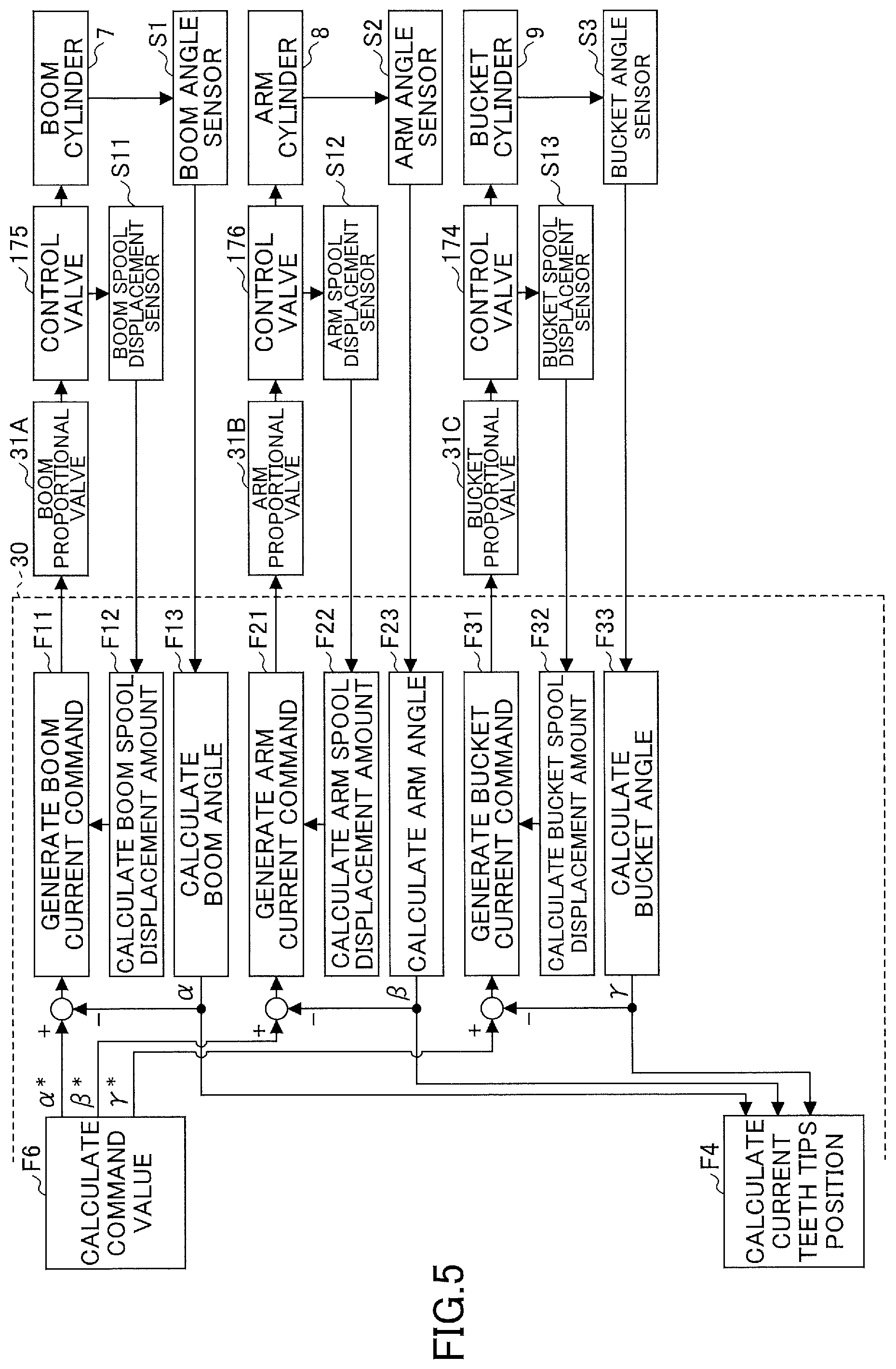
[0121] Next, the functional element F6 is described in detail with reference to FIG. 5. FIG. 5 is a block diagram illustrating an example configuration of the functional element F6 that calculates various command values.
[0122] As illustrated in FIG. 5, the controller 30 further includes functional elements F11 through F13, F21 through F23, and F31 through F33 associated with generation of command values. The functional elements may be constituted of software, hardware, or a combination of software and hardware.
[0123] The functional elements F11 through F13 are functional elements associated with the boom command value .alpha.*. The functional elements F21 through F23 are functional elements associated with the arm command value .beta.*. The functional elements F31 through F33 are functional elements associated with the bucket command value .gamma.*.
[0124] The functional elements F11, F21, and F31 are configured to generate a current command output to the proportional valve 31. According to this embodiment, the functional element F11 outputs a boom current command to the boom proportional valve 31A (see FIG. 3), the functional element F21 outputs an arm current command to the arm proportional valve 31B (see FIG. 3), and the functional element F31 outputs a bucket current command to a bucket proportional valve 31C.
[0125] The functional elements F12, F22, and F32 are configured to calculate the amount of displacement of a spool that is a constituent of a spool valve. According to this embodiment, the functional element F12 calculates the amount of displacement of a boom spool that is a constituent of the control valve 175 pertaining to the boom cylinder 7 based on the output of a boom spool displacement sensor S11. The functional element F22 calculates the amount of displacement of an arm spool that is a constituent of the control valve 176 pertaining to the arm cylinder 8 based on the output of an arm spool displacement sensor S12. The functional element F13 calculates the amount of displacement of a bucket spool that is a constituent of the control valve 174 pertaining to the bucket cylinder 9 based on the output of a bucket spool displacement sensor S13.
[0126] The functional elements F13 through F23 are configured to calculate the rotation angle of a working body. According to this embodiment, the functional element F13 calculates the boom angle .alpha. based on the output of the boom angle sensor S1. The functional element F23 calculates the arm angle .beta. based on the arm angle sensor S2. The functional element F33 calculates the bucket angle .gamma. based on the output of the bucket angle sensor S3.
[0127] Specifically, the functional element F11 basically so generates the boom current command to the boom proportional valve 31A as to eliminate the difference between the boom command value .alpha.* generated by the functional element F6 and the boom angle .alpha. calculated by the functional element F13. At this point, the functional element F11 so adjusts the boom current command as to eliminate the difference between an intended boom spool displacement amount derived from the boom current command and the boom spool displacement amount calculated by the functional element F12. The functional element F11 outputs the adjusted boom current command to the boom proportional valve 31A.
[0128] The boom proportional valve 31A changes the opening area in accordance with the boom current command to cause a pilot pressure commensurate with the size of the boom current command to act on a pilot port of the control valve 175. The control valve 175 moves the boom spool in accordance with the pilot pressure to cause hydraulic oil to flow into the boom cylinder 7. The boom spool displacement sensor S11 detects the displacement of the boom spool and feeds the detection result back to the functional element F12 of the controller 30. The boom cylinder 7 extends or retracts according as hydraulic oil flows in to move up or down the boom 4. The boom angle sensor S1 detects the rotation angle of the vertically moving boom 4 and feeds the detection result back to the functional element F13 of the controller 30. The functional element F13 feeds the calculated boom angle .alpha. back to the functional element F4.
[0129] The functional element F21 basically so generates the arm current command to the arm proportional valve 31B as to eliminate the difference between the arm command value .beta.* generated by the functional element F6 and the arm angle .beta. calculated by the functional element F23. At this point, the functional element F21 so adjusts the arm current command as to eliminate the difference between an intended arm spool displacement amount derived from the arm current command and the arm spool displacement amount calculated by the functional element F22. The functional element F21 outputs the adjusted arm current command to the arm proportional valve 31B.
[0130] The arm proportional valve 31B changes the opening area in accordance with the arm current command to cause a pilot pressure commensurate with the size of the arm current command to act on a pilot port of the control valve 176. The control valve 176 moves the arm spool in accordance with the pilot pressure to cause hydraulic oil to flow into the arm cylinder 8. The arm spool displacement sensor S12 detects the displacement of the arm spool and feeds the detection result back to the functional element F22 of the controller 30. The arm cylinder 8 extends or retracts according as hydraulic oil flows in to open or close the arm 5. The arm angle sensor S2 detects the rotation angle of the opening or closing arm 5 and feeds the detection result back to the functional element F23 of the controller 30. The functional element F23 feeds the calculated arm angle .beta. back to the functional element F4.
[0131] Likewise, the functional element F31 basically so generates the bucket current command to the bucket proportional valve 31C as to eliminate the difference between the bucket command value .gamma.* generated by the functional element F6 and the bucket angle .gamma. calculated by the functional element F33. At this point, the functional element F31 so adjusts the bucket current command as to eliminate the difference between an intended bucket spool displacement amount derived from the bucket current command and the bucket spool displacement amount calculated by the functional element F32. The functional element F31 outputs the adjusted bucket current command to the bucket proportional valve 31C.
[0132] The bucket proportional valve 31C changes the opening area in accordance with the bucket current command to cause a pilot pressure commensurate with the size of the bucket current command to act on a pilot port of the control valve 174. The control valve 174 moves the bucket spool in accordance with the pilot pressure to cause hydraulic oil to flow into the bucket cylinder 9. The bucket spool displacement sensor S13 detects the displacement of the bucket spool and feeds the detection result back to the functional element F32 of the controller 30. The bucket cylinder 9 extends or retracts according as hydraulic oil flows in to open or close the bucket 6. The bucket angle sensor S3 detects the rotation angle of the opening or closing bucket 6 and feeds the detection result back to the functional element F33 of the controller 30. The functional element F33 feeds the calculated bucket angle .gamma. back to the functional element F4.
[0133] As described above, the controller 30 forms a three-stage feedback loop for each working body. That is, the controller 30 forms a feedback loop associated with the amount of spool displacement, a feedback loop associated with the rotation angle of a working body, and a feedback loop associated with the teeth tips position. Therefore, the controller 30 can control the movement of the teeth tips of the bucket 6 with high accuracy during automatic control.
[0134] Next, an effect produced by the emergency stop function is described with reference to FIGS. 6 through 9. FIGS. 6 through 9 relate to the movement of the shovel 100 when part LP (see FIG. 7) of the ground supporting the shovel 100 collapses during slope finishing work. Specifically, FIGS. 6 through 9 relate to the movement of the shovel 100 when the operator performs an arm opening operation out of reflex to prevent the tipping of the shovel 100 in response to the forward tilting of the shovel 100 due to the collapse of the part LP of the ground under the front end of the lower traveling body 1. The operator intends to stop the forward tilting of the shovel 100 by causing the bucket 6 to contact the slope by opening the arm 5.
[0135] More specifically, FIG. 6 is a diagram illustrating the state of the hydraulic system when an arm opening operation has been performed during the automatic excavation control in the shovel 100 where the emergency stop function is disabled, and corresponds to FIG. 3. FIG. 7 is a diagram illustrating the movement of the excavation attachment when an aim opening operation has been performed during the automatic excavation control in the shovel 100 where the emergency stop function is disabled, and corresponds to FIG. 1.
[0136] In the case where the emergency stop function is disabled, when the arm operating lever 26B is operated in the arm opening direction with the MC switch 42A being pressed as illustrated in FIG. 6, the hydraulic system increases a pilot pressure that acts on each of the left pilot port of the control valve 176L and the right pilot port of the control valve 176R in order to retract the arm cylinder 8 to open the arm 5. Therefore, the arm 5 opens as intended by the operator as indicated by arrow AR1 of FIG. 7.
[0137] At this point, the controller 30 detects the operation of the aim operating lever 26B in the arm opening direction based on the output of the operating pressure sensor 29B. As the shovel 100 tilts forward, the teeth tips of the bucket 6 move toward the intended work surface. Therefore, the controller 30 performs a boom raising operation to prevent the teeth tips of the bucket 6 from moving down below the intended work surface. Specifically, the controller 30 outputs a control command to the proportional valve 31AL to cause a predetermined pilot pressure to act on each of the right pilot port of the control valve 175L and the left pilot port of the control valve 175R, in order to extend the boom cylinder 7 to raise the boom 4 according as the arm 5 opens. Therefore, contrary to the operator's intention, the boom 4 rises as indicated by arrow AR2 of FIG. 7, and the vertical distance between the teeth tips of the bucket 6 and an intended work surface TS is maintained at a value Dl against the operator's intention as illustrated in FIG. 7. That is, the operator cannot support the shovel 100 by causing the bucket 6 to contact the slope. As a result, the shovel 100 further tilts forward as indicated by arrow A3 of FIG. 7.
[0138] In contrast, in the case where the emergency stop function is enabled, the controller 30 can prevent the excavation attachment from automatically moving against the operator's intention as described above. FIG. 8 is a diagram illustrating the state of the hydraulic system when an arm opening operation has been performed during the automatic excavation control in the shovel 100 where the emergency stop function is enabled, and corresponds to FIG.
[0139] 3. FIG. 9 is a diagram illustrating the movement of the excavation attachment when an arm opening operation has been performed during the automatic excavation control in the shovel 100 where the emergency stop function is enabled, and corresponds to FIG. 1.
[0140] In the case where the emergency stop function is enabled, when the arm operating lever 26B is operated in the arm opening direction as illustrated in FIG. 8, the hydraulic system increases a pilot pressure that acts on each of the left pilot port of the control valve 176L and the right pilot port of the control valve 176R in order to retract the arm cylinder 8 to open the arm 5, the same as in the case where the emergency stop function is disabled. Therefore, the arm 5 opens as intended by the operator as indicated by arrow AR4 of FIG. 9.
[0141] At this point, the controller 30 detects the operation of the arm operating lever 26B in the arm opening direction based on the output of the operating pressure sensor 29B. Then, the controller 30 determines whether a predetermined condition for stopping automatic control is satisfied. For example, the controller 30 determines that the predetermined condition is satisfied when the operation speed of the arm operating lever 26B in the arm opening direction exceeds a predetermined speed. In response to determining that the predetermined condition is satisfied, the controller 30 stops automatic control. Thus, even during automatic control, the controller 30 can switch the operating mode of the shovel 100 from the automatic control mode to the manual control mode.
[0142] When automatic control is stopped, unlike in the case where the emergency stop function is disabled, the controller 30 does not output a control command to the proportional valve 31AL. Therefore, the controller 30 does not cause a predetermined pilot pressure to act on each of the right pilot port of the control valve 175L and the left pilot port of the control valve 175R. That is, the controller 30 does not extend the boom cylinder 7 and does not raise the boom 4 according as the arm 5 opens. That is, as illustrated in FIG. 9, the boom 4 does not rise contrary to the operator's intention. As a result, the vertical distance between the teeth tips of the bucket 6 and the intended work surface TS is reduced as the arm 5 opens as intended by the operator, and becomes zero when the arm angle reaches a certain angle. That is, the operator can prevent the shovel 100 from further tilting forward by causing the teeth tips of the bucket 6 to contact the slope as illustrated in FIG. 9.
[0143] Next, the same effect produced by the emergency stop function is described with reference to FIGS. 10 and 11. FIGS. 10 and 11 relate to the movement of the shovel 100 when the part LP of the ground supporting the shovel 100 collapses during slope finishing work with an arm closing operation. Specifically, FIGS. 10 and 11 relate to the movement of the shovel 100 when the operator performs a boom lowering operation out of reflex to prevent the tipping of the shovel 100 in response to the forward tilting of the shovel 100 due to the collapse of the part LP of the ground under the front end of the lower traveling body 1. The operator intends to stop the forward tilting of the shovel 100 by causing the bucket 6 to contact the slope by lowering the boom 4.
[0144] In the case where the emergency stop function is enabled, the controller 30 can prevent the excavation attachment from automatically moving against the operator's intention when the operator has performed a boom lowering operation out of reflex, the same as in the case where the operator has performed an arm opening operation out of reflex. FIG. 10 illustrates the state of the hydraulic system when a boom lowering operation has been performed during the automatic excavation control in the shovel 100 where the emergency stop function is enabled. FIG. 11 illustrates the movement of the excavation attachment when a boom lowering operation has been performed during the automatic excavation control in the shovel 100 where the emergency stop function is enabled.
[0145] In response to detecting the operation of the boom operating lever 26A in the boom lowering direction based on the output of the operating pressure sensor 29A, the controller 30 determines whether a predetermined condition for stopping automatic control is satisfied. For example, the controller 30 determines that the predetermined condition is satisfied when the operation speed of the boom operating lever 26A in the boom lowering direction exceeds a predetermined speed. In response to determining that the predetermined condition is satisfied, the controller 30 stops automatic control.
[0146] When automatic control is stopped, the hydraulic system increases a pilot pressure that acts on the right pilot port of the control valve 175R in order to retract the boom cylinder 7 to lower the boom 4, in response to the operation of the boom operating lever 26A in the boom lowering direction as illustrated in FIG. 10. Therefore, the boom 4 lowers as intended by the operator as indicated by arrow AR5 of FIG. 11. The arm 5 does not automatically move as the boom 4 lowers.
[0147] As a result, the distance between the teeth tips of the bucket 6 and the intended work surface TS is reduced as the boom 4 lowers as intended by the operator, and becomes zero when the arm angle reaches a certain angle. That is, the operator can prevent the shovel 100 from further tilting forward by causing the teeth tips of the bucket 6 to contact the slope as illustrated in FIG. 11.
[0148] According to the above-described configuration, the controller 30 stops automatic control when the boom operating lever 26A or the arm operating lever 26B is rapidly operated. The controller 30, however, may stop automatic control in response to detecting that the pitch angle of the upper turning body 3 is more than or equal to a predetermined angle based on the output of the body tilt sensor S4. The controller 30 may also stop automatic control when the emergency stop switch 48, which is a foot switch installed at the operator's feet in the cabin 10, is stepped on. The controller 30 may also stop automatic control when the MC stop switch 42B is pressed. In these cases as well, the operator can stop the forward tilting of the shovel 100 by causing the bucket 6 to contact the slope by opening the aim 5 or by lowering the boom 4, for example.
[0149] Thus, the shovel 100 according to an embodiment of the present invention includes the lower traveling body 1, the upper turning body 3 turnably mounted on the lower traveling body 1, the excavation attachment serving as an attachment attached to the upper turning body 3, and the controller 30 mounted on the upper turning body 3 to serve as a control device that can perform automatic control. The controller 30 is configured to stop automatic control when information on the movement of the shovel 100 or information on the state of a nearby machine shows an unusual tendency. When the information on the movement of the shovel 100 shows an unusual tendency corresponds to, for example, when the operator may be unable to press the bucket 6 against an upward inclined surface as intended by the operator. The automatic control may be, for example, the automatic excavation control. The automatic control may also be, for example, control to move the working part along an intended trajectory. This configuration enables the shovel 100 to move as intended by the operator even during automatic control.
[0150] The "information on the movement of the shovel 100" may be, for example, information on the operation of the operating apparatus 26 mounted on the upper turning body 3. The controller 30 may be configured to determine that the "information on the movement of the shovel 100 shows an unusual tendency" when the operating apparatus 26 is rapidly operated, for example. "When the operating apparatus 26 is rapidly operated" includes, for example, when the amount of operation per unit time of the arm operating lever serving as the operating apparatus 26 exceeds a predetermined value. The amount of operation per unit time of the arm operating lever may be, for example, the inclination angle per unit time of the arm operating lever.
[0151] The automatic control may be, for example, either the automatic straight facing control or the automatic complex turning control. The "information on the movement of the shovel 100" may be information on the operation of the turning operating lever mounted on the upper turning body 3. In this case, the controller 30 may be configured to determine that the "information on the movement of the shovel 100 shows an unusual tendency" when an operation to turn the upper turning body 3 in a direction opposite to that of turning performed by automatic control is performed.
[0152] Next, automatic control executed by the controller 30 is described in detail with reference to
[0153] FIGS. 12 and 13. FIG. 12 is a block diagram illustrating another example of the relationship between the functional elements F1 through F6 associated with the execution of automatic control in the controller 30, and corresponds to FIG. 4. FIG. 13 is a block diagram illustrating another example configuration of the functional element F6 that calculates various command values.
[0154] The configuration of FIG. 12 is different in that the functional element F2 generates the intended trajectory based on the output of the space recognition device S7, that the functional element F4 obtains a turning angle .delta., and that the functional element F6 calculates a turning command value .delta.* from, but otherwise equal to, the configuration of FIG. 4. Furthermore, the configuration of FIG. 13 is different in including a functional element associated with automatic control of the turning hydraulic motor 2A from, but otherwise equal to, the configuration of FIG. 5. Therefore, the description of a common portion is omitted, and differences are described in detail.
[0155] According to the illustration of FIGS. 12 and 13, the functional element F2 generates a trajectory to be followed by the teeth tips of the bucket 6 as an intended trajectory, based on object data detected by the space recognition device S7. The object data are, for example, information on an object present in an area surrounding the shovel 100, such as the position, shape, etc., of a dump truck.
[0156] The functional element F4 calculates the coordinate point of the bucket 6 as a current teeth tips position, based on the boom angle .alpha., the arm angle .beta., the bucket angle .gamma., and the turning angle .delta. calculated from the output of the turning angular velocity sensor S5. The functional element F4 may use the output of the body tilt sensor S4 in calculating the current teeth tips position.
[0157] When the automatic control mode is selected, the functional element F6 calculates at least one of the boom command value .alpha.*, the arm command value .beta.*, the bucket command value .gamma.*, and the turning command value .delta.* based on the intended teeth tips position calculated by the functional element F5, in order to move the current teeth tips position to the intended teeth tips position.
[0158] Functional elements F41 through F43 are functional elements associated with the turning command value .delta.*. Specifically, the functional element F41 outputs a turning current command to a turning proportional valve 31D. The functional element F42 calculates the amount of displacement of a turning spool that is a constituent of the control valve 173 pertaining to the turning hydraulic motor 2A based on the output of a turning spool displacement sensor S14. The functional element F43 calculates the turning angle .delta. based on the output of the turning angular velocity sensor S5.
[0159] The functional element F41 basically so generates the turning current command to the turning proportional valve 31D as to eliminate the difference between the turning command value .delta.* generated by the functional element F6 and the turning angle .delta. calculated by the functional element F43. At this point, the functional element F41 so adjusts the turning current command as to eliminate the difference between an intended turning spool displacement amount derived from the turning current command and the turning spool displacement amount calculated by the functional element F42. The functional element F41 outputs the adjusted turning current command to the turning proportional valve 31D.
[0160] The turning proportional valve 31D changes the opening area in accordance with the turning current command to cause a pilot pressure commensurate with the size of the turning current command to act on a pilot port of the control valve 173. The control valve 173 moves the turning spool in accordance with the pilot pressure to cause hydraulic oil to flow into the turning hydraulic motor 2A. The turning spool displacement sensor S14 detects the displacement of the turning spool and feeds the detection result back to the functional element F42 of the controller 30. The turning hydraulic motor 2A rotates according as hydraulic oil flows in to turn the upper turning body 3. The turning angular velocity sensor S5 detects the rotation angle of the turning upper turning body 3 and feeds the detection. result back to the functional element F43 of the controller 30. The functional element F43 feeds the calculated turning angle .delta. back to the functional element F4.
[0161] As described above, the controller 30 according to FIGS. 12 and 13 forms a three-stage feedback loop with respect to not only the boom angle .alpha., the aim angle .beta., and the bucket angle .gamma., but also the turning angle .delta.. That is, the controller 30 forms a feedback loop associated with the turning spool displacement amount, a feedback loop associated with the rotation angle of the upper turning body 3, and a feedback loop associated with the teeth tips position. Therefore, the controller 30 can control the movement of the teeth tips of the bucket 6 with high accuracy during automatic control.
[0162] Next, the automatic complex turning control is described with reference to FIGS. 14 and 15. FIGS. 14 and 15 illustrate the movement of the excavation attachment during the work of loading the bed of a dump truck DT with soil. FIG. 14 is a plan view of a work site. FIG. 15 is a side view of the work site as seen from the +Y side. For clarification, FIG. 15 omits graphical representation of the shovel 100 (except for the bucket 6).
[0163] In FIGS. 14 and 15, the excavation attachment indicated by a solid line shows the state of the excavation attachment at the completion of an excavating operation, the excavation attachment indicated by a dotted line shows the state of the excavation attachment during a turning operation, and the excavation attachment indicated by a one-dot chain line shows the state of the excavation attachment immediately before performance of a soil dumping operation.
[0164] Point P11 indicates the central point of the back surface of the bucket 6 at the completion of an excavating operation. Point P12 indicates the central point of the back surface of the bucket 6 during a turning operation. Point P13 indicates the central point of the back surface of the bucket 6 immediately before performance of a soil dumping operation. The thick dashed line connecting Point P11, Point P12, and Point P13 indicates a trajectory followed by the central point of the back surface of the bucket 6. The soil dumping operation is an operation to dump soil in the bucket 6 onto the bed of the dump truck DT.
[0165] According to the automatic complex turning control, for example, the automatic control part 54 automatically extends or retracts at least one of the boom cylinder 7, the arm cylinder 8, and the bucket cylinder 9 such that the central point of the back surface of the bucket 6 moves along a predetermined trajectory, while the operator is manually performing a turning operation. The predetermined trajectory is, for example, an intended trajectory calculated based on information on the dump truck DT including the position, shape, etc., of the dump truck DT. The information on the dump truck DT as a nearby machine is obtained based on, for example, the output of at least one of the space recognition device S7, the communications device T1, etc. In this case, by only operating the turning operating lever, the operator can move the central point of the back surface of the bucket 6 along the predetermined trajectory. That is, by only operating the turning operating lever, the operator can move the bucket 6 near the ground to a position over the bed of the dump truck DT at a height Hd while preventing contact between the excavation attachment and the dump truck DT. By operating the turning operating lever, the operator can move the bucket 6 over the bed of the dump truck DT at the height Hd to a position near the ground while preventing contact between the excavation attachment and the dump truck DT. A trajectory used during clockwise turning (during boom raising and turning) may be either equal to or different from a trajectory used during counterclockwise turning (during boom lowering and turning).
[0166] Next, the emergency stop function associated with the automatic complex turning control is described. This emergency stop function is executed, for example, in response to the shovel 100 operator's reflexive counterclockwise turning operation when the dump truck DT starts to move while the operator is performing a clockwise turning operation to load the bed of the dump truck DT with soil. Specifically, this emergency stop function is executed, for example, in response to the operator's reflexive counterclockwise turning operation to prevent contact between the shovel 100 and the dump truck DT when the dump truck DT that has been stopped suddenly starts to move backward. In this case, the operator intends to move the bucket 6 away from the dump truck DT while maintaining the height of the bucket 6 by turning the upper turning body 3 turning clockwise in the opposite counterclockwise direction.
[0167] For example, when the turning operating lever is rapidly operated in a opposite direction, the automatic control part 54 determines that the "information on the movement of the shovel 100 shows an unusual tendency" and stops the automatic complex turning control.
[0168] When the emergency stop function is disabled, that is, when the automatic complex turning control is not stopped, the automatic control part 54 moves the central point of the back surface of the bucket 6 along the predetermined trajectory even when the turning operating lever is rapidly operated leftward, and therefore lowers the bucket 6 contrary to the operator's intention. The figure indicated by crosshatching in FIG. 15 indicates the position of the bucket 6 whose height is reduced. That is, FIG. 15 illustrates that the bucket 6 at the height of a figure indicated by a dotted line lowers to the height of the figure indicated by crosshatching.
[0169] In contrast, when the emergency stop function is enabled, that is, when the automatic complex turning control is stopped, the automatic control part 54 can cause the central point of the back surface of the bucket 6 to deviate from the predetermined trajectory to move the bucket 6 in response to the leftward rapid operation of the turning operating lever. Therefore, the automatic control part 54 can move the bucket 6 leftward while maintaining the height of the bucket 6 as intended by the operator instead of lowering the bucket 6 against the operator's intention. The figure indicated by oblique line hatching in FIG. 15 indicates the position of the bucket 6 that has been moved leftward while keeping the height. That is, FIG. 15 illustrates that the bucket 6 at the height of a figure indicated by a dotted line moves to the position of the figure indicated by oblique line hatching while remaining at the same height.
[0170] Thus, in the case where the emergency stop function is enabled, when the operator performs a counterclockwise turning operation out of reflex, the controller 30 can prevent the excavation attachment from automatically moving against the operator's operation.
[0171] The controller 30 may be configured to detect the start of the movement (for example, the start of the backward travel) of the dump truck DT based on the output of the space recognition device S7. In this case, after identifying what work a currently performed work is based on the outputs of various sensors, the controller 30 obtains information on the normal state of a nearby machine associated with the work, recorded in advance work by work. For example, in the case of having successfully identified that the currently performed work is loading work that loads the bed of the dump truck DT with soil, the controller 30 obtains information that the normal state of the dump truck DT that is a nearby machine associated with the loading work is a stopped state. When the dump truck DT starts to move during the loading work, the controller 30 can determine that the dump truck DT is in a state different from the normal state. Based on this determination result, the controller 30 can stop automatic control.
[0172] Furthermore, the operating mode of the shovel 100 may include a stop mode, apart from the manual control mode and the automatic control mode. According to this configuration, when the teeth tips of the bucket 6 as the working part are in a region other than the region above the bed of the dump truck DT, the controller 30 may stop automatic control and thereafter switch the operating mode of the shovel 100 from the automatic control mode to the stop mode, in response to detecting the start of the movement of the dump. truck DT. During the stop mode, the controller 30 may stop the movement of the working part in a space between Point P11, indicating the central point of the back surface of the bucket 6 at the completion of an excavating operation, and the dump truck DT, irrespective of whether the operating apparatus 26 is operated. This is for preventing contact between the working part and the dump truck DT by keeping the working part on standby until the dump truck DT stops, namely, by forcibly arresting the movement of the working part until the dump truck DT stops.
[0173] Thus, when detecting the start of the movement of the dump truck DT during the loading work, the controller 30 may switch the operating mode of the shovel 100 from the automatic control mode to the stop mode.
[0174] The operating mode of the shovel 100 may include an avoidance mode, apart from the manual control mode and the automatic control mode. The controller 30 may switch the operating mode of the shovel 100 from the automatic control mode to the avoidance mode, for example, when detecting the start of the movement of the dump truck DT during the loading work and the teeth tips of the bucket 6 as the working part are within a region above the bed of the dump truck DT. During the avoidance mode, the controller 30 may move the teeth tips of the bucket 6 aside to a space between Point P11, indicating the central point of the back surface of the bucket 6 at the completion of an excavating operation, and the dump truck DT, by automatically moving various hydraulic actuators, irrespective of whether the operating apparatus 26 is operated. This is for preventing contact between the working part and the dump truck DT by forcing the working part to move from inside and stay outside a region above the bed of the dump truck DT until the dump truck DT stops.
[0175] Thus, when detecting the start of the movement of the dump truck DT during the loading work, the controller 30 may switch the operating mode of the shovel 100 from the automatic control mode to the avoidance mode.
[0176] The shovel 100 may include a switch related to automatic control, such as the MC switch 42A. In this case, the controller 30 may be configured to execute automatic control when the switch is operated.
[0177] Furthermore, the illustration of FIG. 3 discloses a hydraulic operation system including a hydraulic pilot circuit. For example, according to a hydraulic pilot circuit associated with the boom operating lever 26A, hydraulic oil supplied from the pilot pump 15 to a remote control valve 27A is supplied to a pilot port of the control valve 175 at a flow rate commensurate with the opening degree of the remote control valve 27A opened by the tilt of the boom operating lever 26A. According to a hydraulic pilot circuit associated with the arm operating lever 26B, hydraulic oil supplied from the pilot pump 15 to a remote control valve 27B is supplied to a pilot port of the control valve 176 at a flow rate commensurate with the opening degree of the remote control valve 27B opened by the tilt of the aim operating lever 26B.
[0178] Instead of a hydraulic operation system including such a hydraulic pilot circuit, however, an electric operation system including an electric operating lever may be adopted. In this case, the amount of lever operation of the electric operating lever is input to the controller 30 as an electrical signal. Furthermore, a solenoid valve is placed between the pilot pump 15 and a pilot port of each control valve. The solenoid valve is configured to operate in response to an electrical signal from the controller 30.
[0179] According to this configuration, when a manual operation using the electric operating lever is performed, the controller 30 can move each control valve by increasing or decreasing a pilot pressure by controlling the solenoid valve with an electrical signal commensurate with the amount of lever operation.
[0180] When an electric operation system including an electric operating lever is adopted, the controller 30 can easily switch the manual control mode and the automatic control mode. When the controller 30 switches the manual control mode to the automatic control mode, control valves may be independently controlled in response to an electrical signal commensurate with the amount of lever operation of a single electric operating lever.
[0181] FIG. 16 illustrates an example configuration of an electric operation system. Specifically, the electric operation system of FIG. 16 is an example of a boom operation system, and mainly includes the pilot pressure-operated control valve 17, the boom operating lever 26A serving as an electric operating lever, the controller 30, a solenoid valve for boom raising operation, and a solenoid valve for boom lowering operation. The electric operation system of FIG. 16 may also be likewise applied to an arm operation system, a bucket operation system, etc.
[0182] The pilot pressure-operated control valve 17 includes the control valve 175 (see FIG. 2) pertaining to the boom cylinder 7, the control valve 176 (see FIG. 2) pertaining to the arm cylinder 8, the control valve 174 (see FIG. 2) pertaining to the bucket cylinder 9, etc. A solenoid valve 60 is configured to be able to adjust the flow area of a conduit connecting the pilot pump 15 and the raising-side pilot port of the control valve 175. A solenoid valve 62 is configured to be able to adjust the flow area of a conduit connecting the pilot pump 15 and the lowering-side pilot port of the control valve 175.
[0183] When a manual operation is performed, the controller 30 generates a boom raising operation signal (an electrical signal) or a boom lowering operation signal (an electrical signal) in accordance with an operation signal (electrical signal) output by an operation signal generating part 26Aa of the boom operating lever 26A. The operation signal output by the operation signal generating part 26Aa of the boom operating lever 26A is an electrical signal that changes in accordance with the amount of operation and the direction of operation of the boom operating lever 26A.
[0184] Specifically, when the boom operating lever 26A is operated in the boom raising direction, the controller 30 outputs a boom raising operation signal (an electrical signal) commensurate with the amount of lever operation to the solenoid valve 60. The solenoid valve 60 adjusts the flow area in accordance with the boom raising operation signal (electrical signal) to control a pilot pressure that acts on the raising-side pilot port of the control valve 175. Likewise, when the boom operating lever 26A is operated in the boom lowering direction, the controller 30 outputs a boom lowering operation signal (an electrical signal) commensurate with the amount of lever operation to the solenoid valve 62. The solenoid valve 62 adjusts the flow area in accordance with the boom lowering operation signal (electrical signal) to control a pilot pressure that acts on the lowering-side pilot port of the control valve 175.
[0185] In the case of executing automatic control, for example, the controller 30 generates a boom raising operation signal (an electrical signal) or a boom lowering operation signal (an electrical signal) in accordance with a correcting operation signal (an electrical signal) instead of the operation signal output by the operation signal generating part 26Aa of the boom operating lever 26A. The correcting operation signal may be either an electrical signal generated by the controller 30 or an electrical signal generated by an external control device different than the controller 30.
[0186] Furthermore, information obtained by the shovel 100 may be shared with a manager, other shovel operators, etc., through a shovel management system SYS as illustrated in FIG. 17. FIG. 17 is a schematic diagram illustrating an example configuration of the shovel management system SYS. The management system SYS is a system that manages the shovel 100. According to this embodiment, the management system SYS is constituted mainly of the shovel 100, an assist device 200, and a management apparatus 300. Each of the shovel 100, the assist device 200, and the management apparatus 300 constituting the management system SYS may be one or more in number. According to the illustration of FIG. 17, the management system SYS includes the single shovel 100, the single assist device 200, and the single management apparatus 300.
[0187] The assist device 200 is typically a portable terminal device, and is, for example, a computer including a processor, such as a notebook PC, a tablet PC, or a smartphone carried by a worker or the like at a construction site. The assist device 200 may also be a computer carried by the operator of the shovel 100. The assist device 200, however, may also be a stationary terminal device.
[0188] The management apparatus 300 is typically a stationary terminal device, and is, for example, a server computer including a processor and installed in a management center or the like outside a construction site. The management apparatus 300 may also be a portable computer including a processor (for example, a portable terminal device such as a notebook PC, a tablet PC, or a smartphone).
[0189] At least one of the assist device 200 and the management apparatus 300 (hereinafter, "assist device 200, etc.") may include a monitor and an operating apparatus for remote control. In this case, the operator operates the shovel 100 using the operating apparatus for remote control. The operating apparatus for remote control is connected to the controller 30 through, for example, a communications network such as a radio communications network.
[0190] According to the shovel management system SYS as described above, the controller 30 of the shovel 100 may transmit information on at least one of the time, location, etc., of the stoppage of automatic control to the assist device 200, etc. At this point, the controller 30 may transmit a peripheral image that is an image captured by the image capturing device S6 to the assist device 200, etc. The peripheral image may be multiple peripheral images captured within a predetermined period including the time of the stoppage of automatic control. Furthermore, the controller 30 may transmit data on the work details of the shovel 100, data on the attitude of the shovel 100, data on the posture of the excavation attachment, etc., within a predetermined period including the time of the stoppage of automatic control to the assist device 200, etc. This is for enabling a manager using the assist device 200, etc., to obtain information on a work site as illustrated in FIGS. 9, 11, 14 and 15. That is, this is for enabling the manager to analyze the cause of such an operation as to stop automatic control having been performed, etc., and further for enabling the manager to improve the work environment of the shovel 100 based on the results of the analysis.
[0191] Thus, the management system SYS of the shovel 100 according to the embodiment of the present invention includes the shovel 100 that stores at least one of the time, location, attitude, and peripheral image of the stoppage of automatic control executed by the shovel 100 in the storage device 47 and transmits the stored at least one of the time, location, attitude, and peripheral image to the outside with desired timing, and the management apparatus 300 that receives the at least one of the time, location, attitude, and peripheral image transmitted by the shovel 100 and outputs at least one of the received attitude and peripheral image. The attitude is, for example, at least one of the attitude of the shovel 100 when automatic control is stopped and the posture of the excavation attachment when automatic control is stopped. The management apparatus 300 enables the manager to recognize the attitude of the shovel 100 by, for example, displaying an illustration image on the monitor. The management apparatus 300 may also enable the manager to recognize the attitude of the shovel 100 by, for example, outputting audio information.
[0192] An embodiment of the present invention is described in detail above. The present invention, however, is not limited to the above-described embodiment. Various variations, substitutions, etc., may be applied to the above-described embodiment without departing from the scope of the present invention. Furthermore, the separately described features may be suitably combined as long as no technical contradiction is caused.
[0193] For example, according to the above-described embodiment, the controller 30 causes the upper turning body 3 to face straight to the intended work surface by automatically operating the turning hydraulic motor 2A. The controller 30, however, may also cause the upper turning body 3 to face straight to the intended work surface by automatically operating a turning motor generator.
[0194] Furthermore, the operational data, which are generated in accordance with the operating apparatus or the operating apparatus for remote control, may also be automatically generated by a predetermined operation program.
[0195] Furthermore, the controller 30 may also cause the upper turning body 3 to face straight to the intended work surface by operating other actuators. For example, the controller 30 may cause the upper turning body 3 to face straight to the intended work surface by automatically operating the left side traveling hydraulic motor 1L and the right side traveling hydraulic motor 1R.
* * * * *
D00000
D00001
D00002
D00003
D00004
D00005
D00006
D00007
D00008
D00009
D00010
D00011
D00012

D00013

D00014
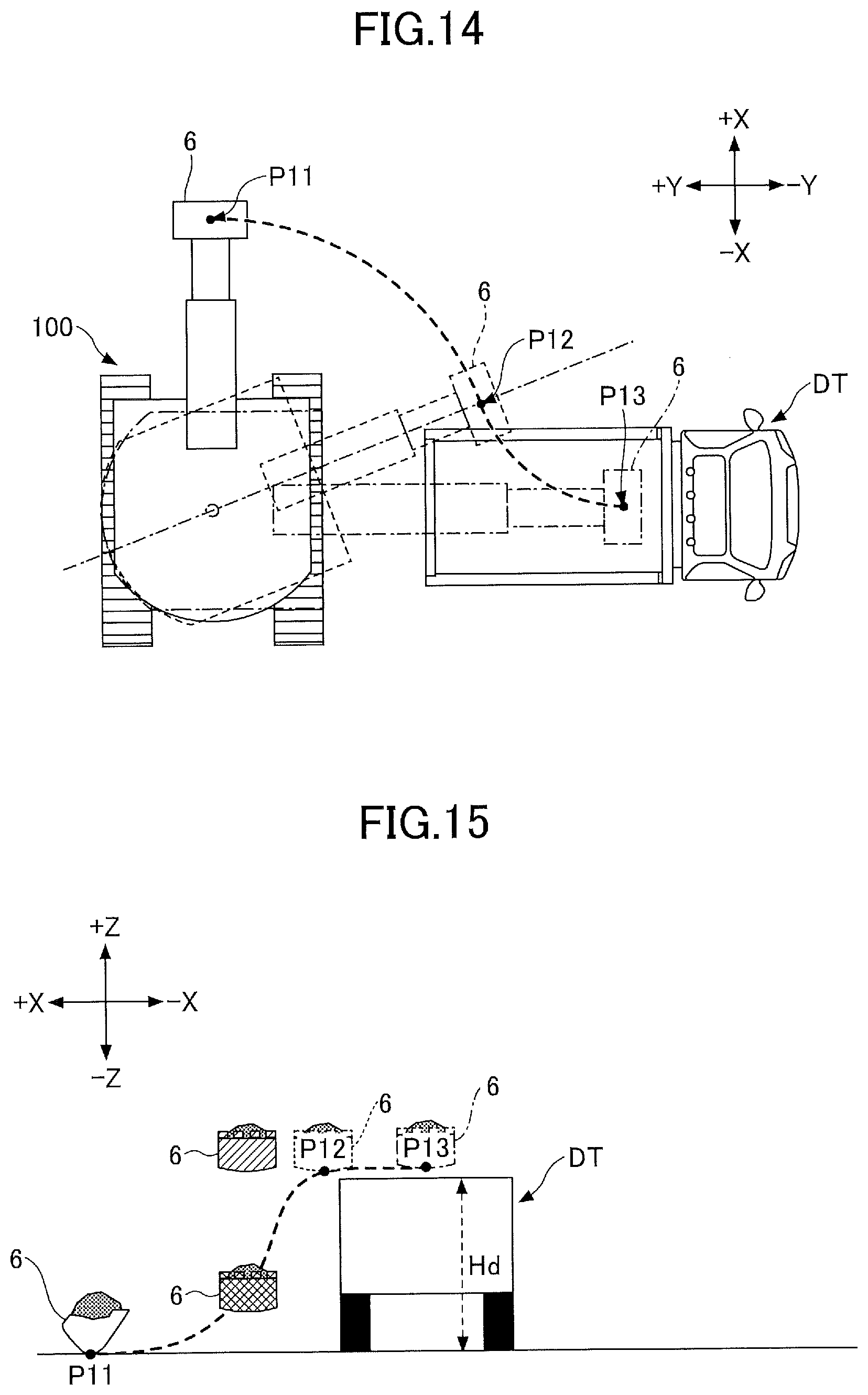
D00015

D00016

XML
uspto.report is an independent third-party trademark research tool that is not affiliated, endorsed, or sponsored by the United States Patent and Trademark Office (USPTO) or any other governmental organization. The information provided by uspto.report is based on publicly available data at the time of writing and is intended for informational purposes only.
While we strive to provide accurate and up-to-date information, we do not guarantee the accuracy, completeness, reliability, or suitability of the information displayed on this site. The use of this site is at your own risk. Any reliance you place on such information is therefore strictly at your own risk.
All official trademark data, including owner information, should be verified by visiting the official USPTO website at www.uspto.gov. This site is not intended to replace professional legal advice and should not be used as a substitute for consulting with a legal professional who is knowledgeable about trademark law.