Economical Multi-scale Reinforced Composites
Lynch-Branzoi; Jennifer K. ; et al.
U.S. patent application number 16/868095 was filed with the patent office on 2020-11-12 for economical multi-scale reinforced composites. The applicant listed for this patent is Rutgers, The State University of New Jersey. Invention is credited to Justin W. Hendrix, Jennifer K. Lynch-Branzoi, Thomas J. Nosker, Arya S. Tewatia.
| Application Number | 20200354572 16/868095 |
| Document ID | / |
| Family ID | 1000004867456 |
| Filed Date | 2020-11-12 |


View All Diagrams
| United States Patent Application | 20200354572 |
| Kind Code | A1 |
| Lynch-Branzoi; Jennifer K. ; et al. | November 12, 2020 |
ECONOMICAL MULTI-SCALE REINFORCED COMPOSITES
Abstract
Disclosed are co-continuous immiscible polymer blends of a polysulfone and a polyaryletherketone optionally reinforced with carbon fiber. A method of preparing such a co-continuous immiscible polymer blend of a polysulfone and a polyaryletherketone reinforced with a carbon fiber is also disclosed.
| Inventors: | Lynch-Branzoi; Jennifer K.; (Franklin Park, NJ) ; Nosker; Thomas J.; (Stockton, NJ) ; Hendrix; Justin W.; (Washington, DC) ; Tewatia; Arya S.; (Piscataway, NJ) | ||||||||||
| Applicant: |
|
||||||||||
|---|---|---|---|---|---|---|---|---|---|---|---|
| Family ID: | 1000004867456 | ||||||||||
| Appl. No.: | 16/868095 | ||||||||||
| Filed: | May 6, 2020 |
Related U.S. Patent Documents
| Application Number | Filing Date | Patent Number | ||
|---|---|---|---|---|
| 62844544 | May 7, 2019 | |||
| Current U.S. Class: | 1/1 |
| Current CPC Class: | C08J 3/005 20130101; C08L 61/16 20130101; C08J 5/042 20130101; C08L 81/06 20130101 |
| International Class: | C08L 81/06 20060101 C08L081/06; C08L 61/16 20060101 C08L061/16; C08J 5/04 20060101 C08J005/04 |
Claims
1. A co-continuous immiscible polymer blend of a polysulfone and a polyaryletherketone.
2. The immiscible polymer blend of claim 1, wherein the blend is reinforced with carbon fibers.
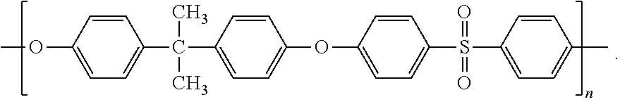
3. The co-continuous immiscible polymer blend of claim 1, wherein the polysulfone has the structure ##STR00005##
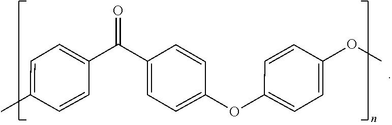
4. The co-continuous immiscible polymer blend of claim 1, wherein the polyaryletherketone is polyetheretherketone (PEEK), having the structure ##STR00006##
5. The co-continuous immiscible polymer blend of claim 2, wherein the carbon fiber is selected from the group consisting of chopped carbon microfiber (CF), carbon nanofiber (CNF) and mixtures thereof.
6. The co-continuous immiscible polymer blend of claim 1, wherein the amount of the polysulfone in the polyaryletherketone ranges from about 20% to about 50% by weight.
7. The co-continuous immiscible polymer blend of claim 6, wherein the amount of the polysulfone in the polyaryletherketone ranges from about 40% to about 50% by weight.
8. The co-continuous immiscible polymer blend of claim 6, wherein the amount of the polysulfone in the polyaryletherketone is about 45% by weight.
9. The co-continuous immiscible polymer blend of claim 5, wherein carbon microfiber is present in an amount ranging from about 5% to about 30% by weight.
10. The co-continuous immiscible polymer blend of claim 9, wherein the amount of carbon microfiber present ranges from about 15% to about 25% by weight.
11. The co-continuous immiscible polymer blend of claim 9, wherein the amount of carbon microfiber present is about 20% by weight.
12. The co-continuous immiscible polymer blend of claim 5, wherein carbon nanofiber is present in an amount ranging from about 0.5% to about 5% by weight.
13. The co-continuous immiscible polymer blend of claim 12, wherein the amount of carbon nanofiber present ranges from about 1% to about 4% by weight.
14. The co-continuous immiscible polymer blend of claim 12, wherein the amount of carbon nanofiber present is about 2.5% by weight.
15. The co-continuous immiscible polymer blend of claim 5, wherein carbon nanofiber is present in an amount from about 0.5% to about 2% by weight together with carbon microfiber in an amount from about 5% to about 15% by weight.
16. The co-continuous immiscible polymer blend of claim 15, wherein carbon nanofiber is present in an amount of about 1% by weight together with carbon microfiber an amount of about 10% by weight.
17. A method of preparing a co-continuous immiscible polymer blend of a polysulfone and a polyaryletherketone reinforced with a carbon fiber, comprising the steps of: a) preparing a carbon fiber-reinforced polysulfone, containing a reinforcing amount of carbon microfiber, carbon nanofiber, or a mixture thereof; b) blending the carbon fiber-reinforced polysulfone with a polyaryletherketone, optionally reinforced with a reinforcing amount of carbon microfiber, carbon nanofiber, or a mixture thereof, in a blend ratio where the viscosity ratio of the components is equivalent to the composition ratio at constant processing temperature and shear rate.
Description
CROSS-REFERENCE TO RELATED APPLICATIONS
[0001] This application claims the benefit of U.S. Provisional Patent Application Ser. No. 62/844,544, filed May 7, 2019, which is herein incorporated by reference in its entirety.
FIELD OF THE INVENTION
[0002] The present disclosure relates to economical multi-scale reinforced composites comprising carbon fiber-reinforced co-continuous immiscible polymer blends (IMPBs) of a polysulfone, such as a polyarylethersulfone (PSU) and a polyaryletherketone, such as polyetheretherketone (PEEK).
BACKGROUND
[0003] The development of co-continuous immiscible polymer blends (IMPBs) offer versatility in tailoring physical properties via synergistic combinations of the blend components, and is more economical than chemical synthesis and development of a new polymer. Additional physical property enhancements are possible by fiber reinforcement of the lower viscosity phase to achieve fiber self-alignment within the IMPB composite during processing, as in fiberglass reinforced polypropylene blended with HDPE, (FRPP)/HDPE. The oriented FRPP/HDPE composite requires only 1/3 of the fibers versus a randomly oriented fiberglass reinforced polymer in order to achieve the same properties as measured along a particular axis. This translates to lower costs and less wear on processing equipment.
[0004] Fiber-reinforced PEEK is a useful fiber-reinforced polymer matrix composite useful for fabrication of various lightweight yet strong component parts in the high-end polymer market. However, the cost of PEEK is relatively high. There is a need for more cost-effective fiber-reinforced high-end polymer materials.
SUMMARY
[0005] The present disclosure presents solutions to meet these needs.
[0006] Thus, a primary goal of the present invention is to develop a high performance IMPB, and multi-scale reinforcement, of this IMPB to result in an amplified effect on the composite's properties through self-alignment of the reinforcing agents during processing. The high performance engineering-grade polymers utilized include PEEK and PSU as commercially available representatives of the polyaryletherketone and polysulfone families, respectively. The cost of PSU can be at least one-third the cost of PEEK, depending on the quantity purchased, so a co-continuous IMPB would reduce cost. It was discovered that addition of PSU dilutes the material cost of PEEK without sacrificing performance. The fiber-reinforcing agents were selected from carbon nanofiber (CNF) and chopped carbon microfiber (CF).
[0007] Advantages of utilizing IMPB concepts and multi-scale reinforcement include: [0008] 1. Self-alignment of the reinforcing agent (CNF, CF) during processing; [0009] 2. An amplified effect of the reinforcing agent on the resulting composite's properties; [0010] 3. Less reinforcing agents required to achieve the same mechanical properties of a reinforced homo-polymer; [0011] 4. Overall reduced costs; [0012] 5. A light-weight alternative to traditional materials used in the aerospace, automotive, and high-end construction industries.
[0013] One aspect of the invention is directed to a co-continuous immiscible polymer blend of a polysulfone and a polyaryletherketone reinforced with a carbon fiber. The polysulfone can have the structure
##STR00001##
The polyaryletherketone can be polyetheretherketone (PEEK), having the structure
##STR00002##
The carbon fiber can be selected from the group consisting of chopped carbon microfiber (CF), carbon nanofiber (CNF) and mixtures thereof. The amount of the polysulfone in the polyaryletherketone can range from about 20% to about 50% by weight, or from about 40% to about 50% by weight, or the amount of polysulfone in the polyaryletherketone can be about 45% by weight.
[0014] The amount of carbon microfiber present in the co-continuous immiscible polymer blend can range from about 5% to about 30% by weight, or about 15% to about 25% by weight, or the amount of carbon microfiber present in the co-continuous immiscible polymer blend can be about 20% by weight. The amount of carbon nanofiber in the co-continuous immiscible polymer blend can range from about 0.5% to about 5% by weight, or about 1% to about 4% by weight, or the amount of carbon nanofiber in the co-continuous immiscible polymer blend can be about 2.5% by weight. Further, the carbon nanofiber can be present in an amount from about 0.5% to about 2% by weight together with carbon microfiber in an amount from about 5% to about 15% by weight. The carbon nanofiber can be present in an amount of about 1% by weight together with carbon microfiber in an amount of about 10% by weight.
[0015] Another aspect of the invention is directed to a method of preparing a co-continuous immiscible polymer blend of a polysulfone and a polyaryletherketone reinforced with a carbon fiber, comprising the steps of a) preparing a carbon fiber-reinforced polysulfone, containing a reinforcing amount of carbon microfiber, carbon nanofiber, or a mixture thereof, and b) blending the carbon fiber-reinforced polysulfone with a polyaryletherketone, optionally reinforced with a reinforcing amount of carbon microfiber, carbon nanofiber, or a mixture thereof, in a blend ratio where the viscosity ratio of the polymer components is equivalent to the composition ratio at constant processing temperature and shear rate.
[0016] Compounding may be performed in a batch mixer or extruder that imparts repetitive high shear rates, elongational flow and distributive mixing. Longer mixing times provide enhanced nano-morphology of the immiscible polymer blend. Furthermore, the morphological properties are tunable by modification of the mixing process. In one embodiment, the shear rate is between about 150 and about 950 s.sup.-1. In another embodiment, the shear rate is between about 250 and about 750 s.sup.-1. In one embodiment the mixing is performed using a single screw extruder that includes one or more mixing elements that impart uniform shear flow in combination with extensional and distributive mixing.
BRIEF DESCRIPTION OF THE DRAWINGS
[0017] The patent or application file contains at least one drawing executed in color. Copies of this patent or patent application publication with color drawing(s) will be provided by the Office upon request and payment of the necessary fee.
[0018] FIG. 1 shows modulus as a function of % PSU in PEEK.
[0019] FIG. 2 shows stress at yield and stress at break as a function of % PSU in PEEK.
[0020] FIG. 3 shows % strain at yield as a function of % PSU in PEEK.
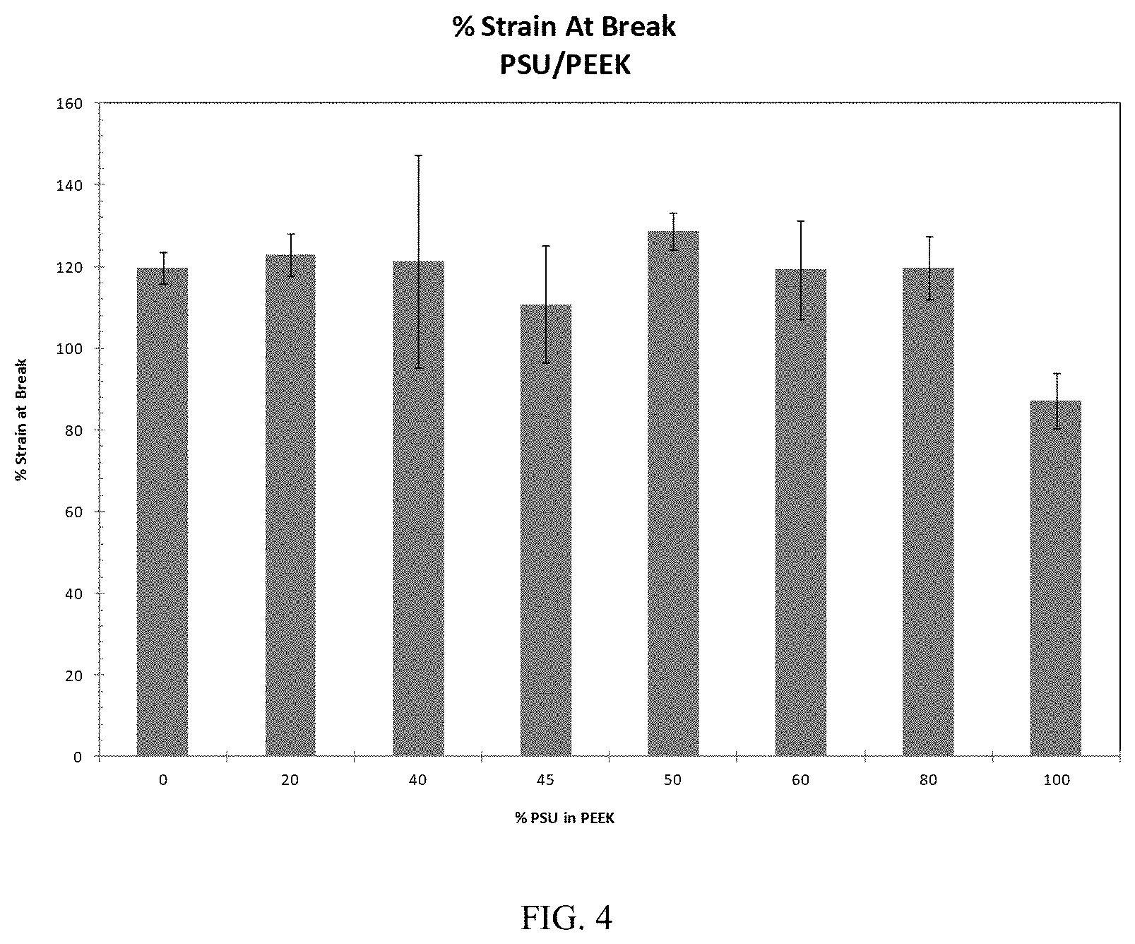
[0021] FIG. 4 shows % strain at break as a function of % PSU in PEEK.
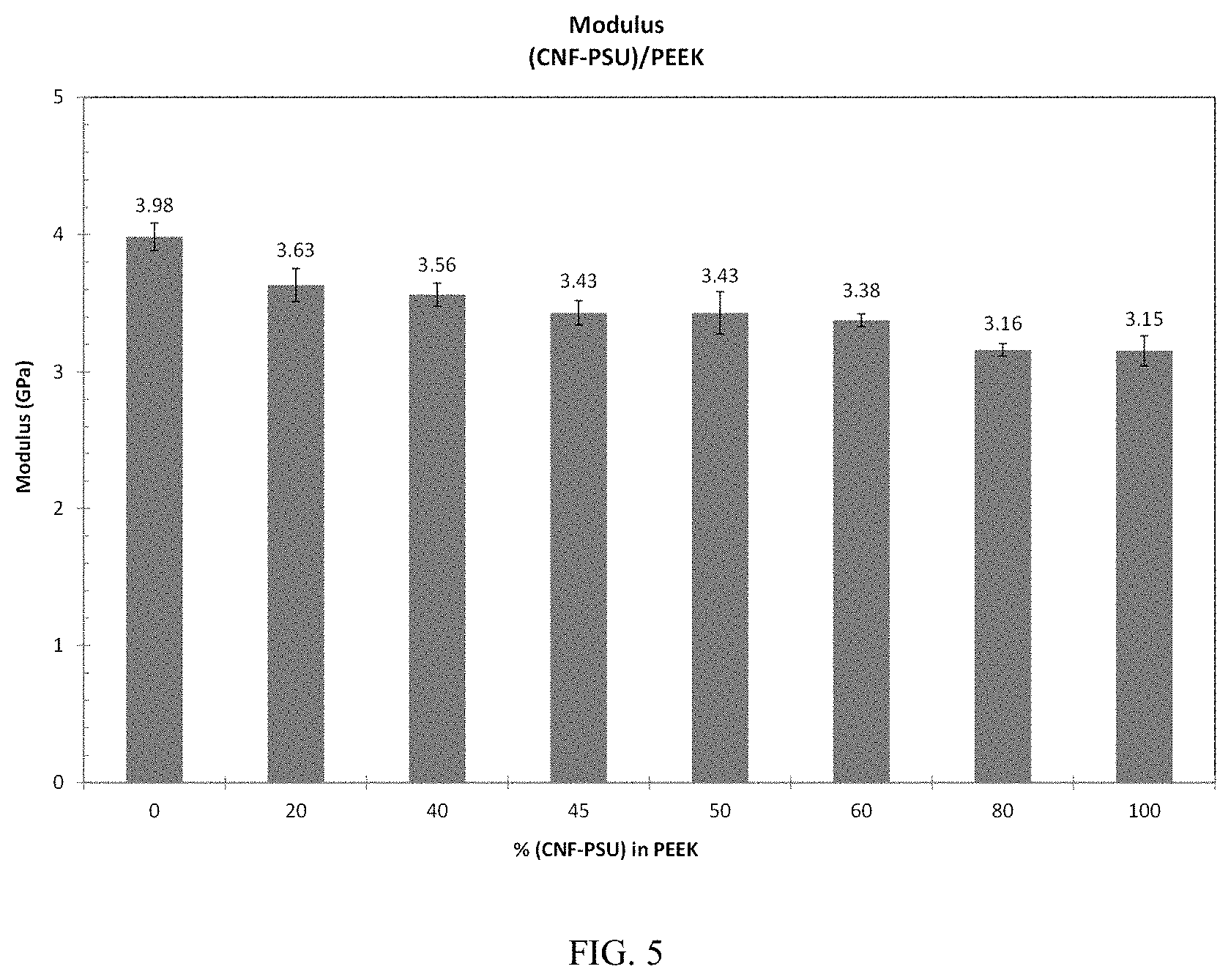
[0022] FIG. 5 shows modulus as a function of % (CNF-PSU) in PEEK.
[0023] FIG. 6 shows stress at yield and stress at break as a function of % (CNF-PSU) in PEEK.
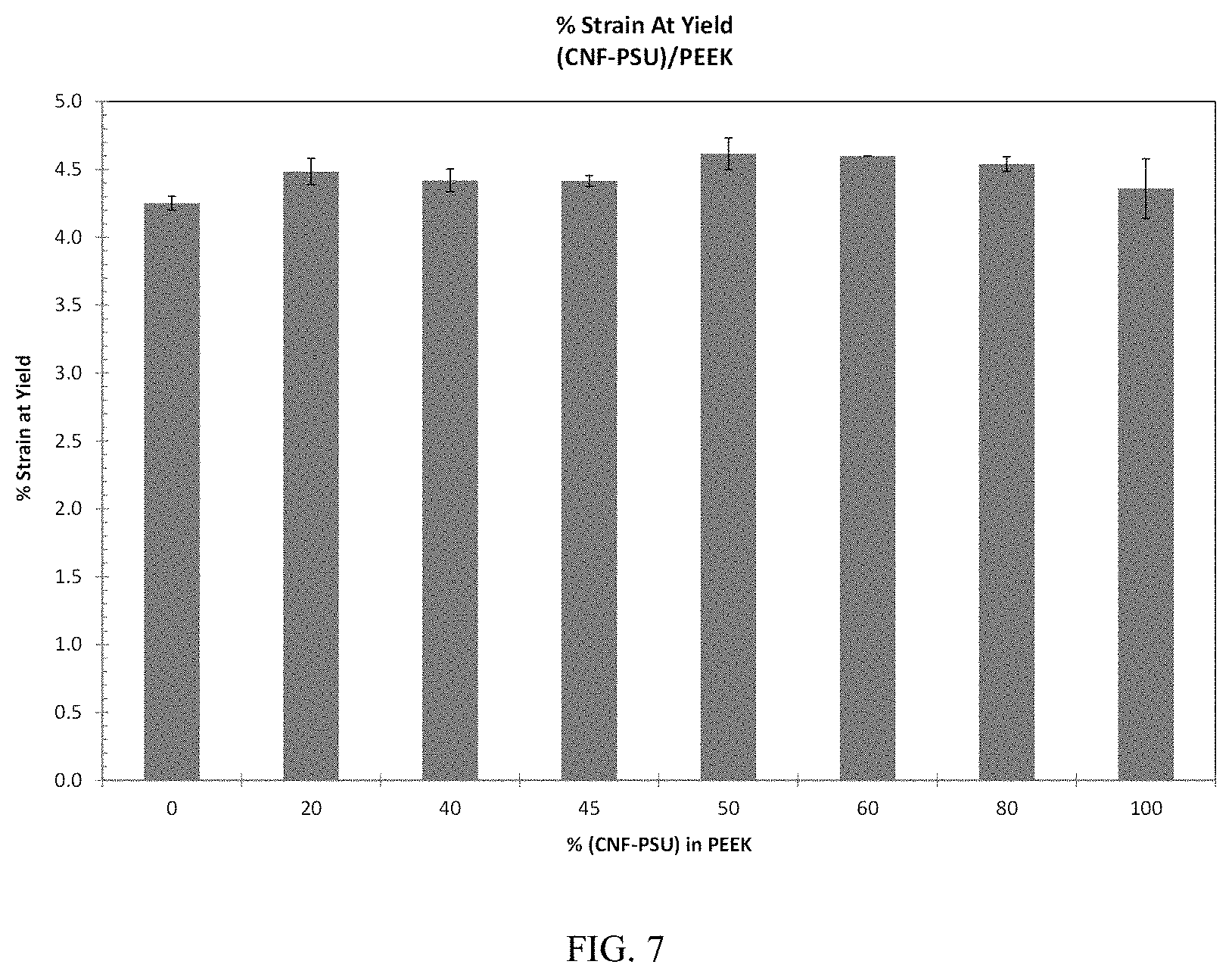
[0024] FIG. 7 shows % strain at yield as a function of % (CNF-PSU) in PEEK.
[0025] FIG. 8 shows % strain at break as a function of % (CNF-PSU) in PEEK.
[0026] FIG. 9 shows modulus as a function of % (CF-PSU) in PEEK.
[0027] FIG. 10 shows stress at yield and stress at break as a function of % (CF-PSU) in PEEK.
[0028] FIG. 11 shows % strain at yield as a function of % (CF-PSU) in PEEK.
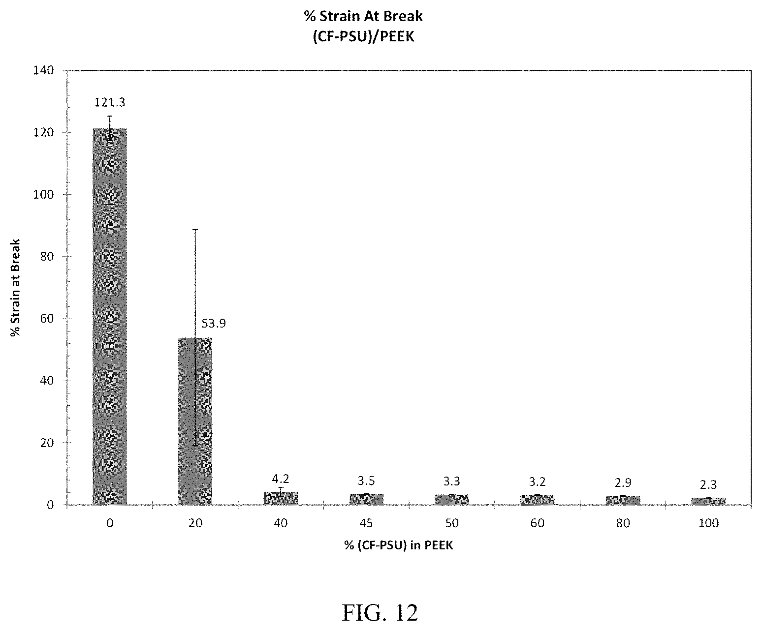
[0029] FIG. 12 shows % strain at break as a function of % (CF-PSU) in PEEK.
[0030] FIG. 13 shows modulus as a function of % (CNF-CF-PSU) in PEEK.
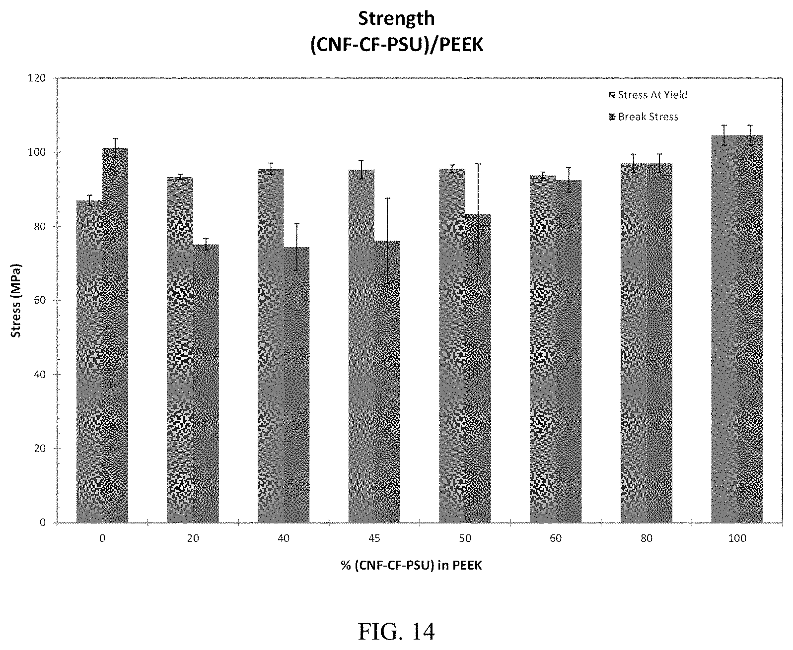
[0031] FIG. 14 shows stress at yield and stress at break as a function of % (CNF-CF-PSU) in PEEK.
[0032] FIG. 15 shows % strain at yield as a function of % (CNF-CF-PSU) in PEEK.
[0033] FIG. 16 shows % strain at break as a function of % (CNF-CF-PSU) in PEEK.
[0034] FIG. 17 shows modulus as a function of % (CNF-CF-PSU) in (CNF-CF-PEEK).
[0035] FIG. 18 shows stress at yield and stress at break as a function of % (CNF-CF-PSU) in (CNF-CF-PEEK).
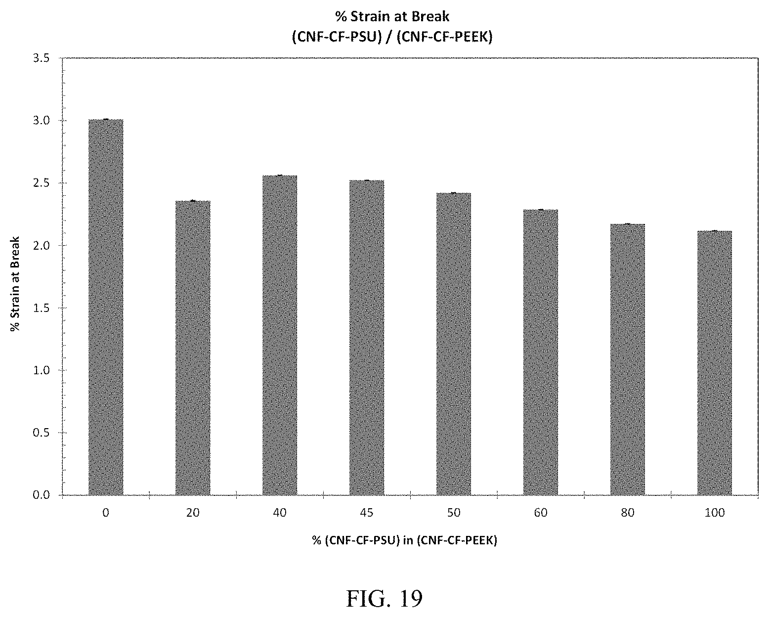
[0036] FIG. 19 shows % strain at break as a function of % (CNF-CF-PSU) in (CNF-CF-PEEK).
[0037] FIG. 20 shows Izod impact resistance of the PSU/PEEK IMPB as a function of wt % PSU in PEEK.
[0038] FIG. 21 shows Izod impact resistance of the (CNF-PSU)/PEEK composite IMPB as a function of wt % (CNF-PSU) in PEEK.
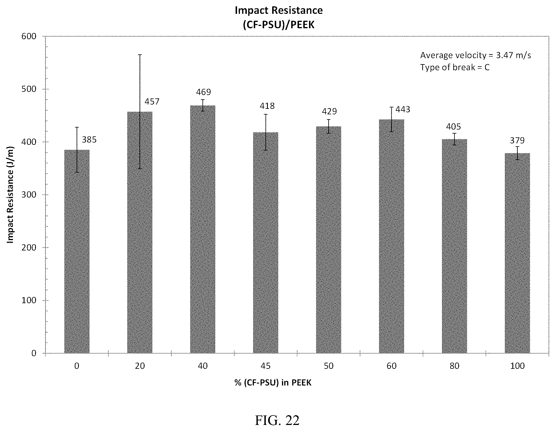
[0039] FIG. 22 shows Izod impact resistance of the (CF-PSU)/PEEK composite IMPB as a function of wt % (CF-PSU) in PEEK.
[0040] FIG. 23 shows Izod impact resistance of the (CNF-CF-PSU)/PEEK composite IMPB as a function of wt % (CNF-CF-PSU) in PEEK.
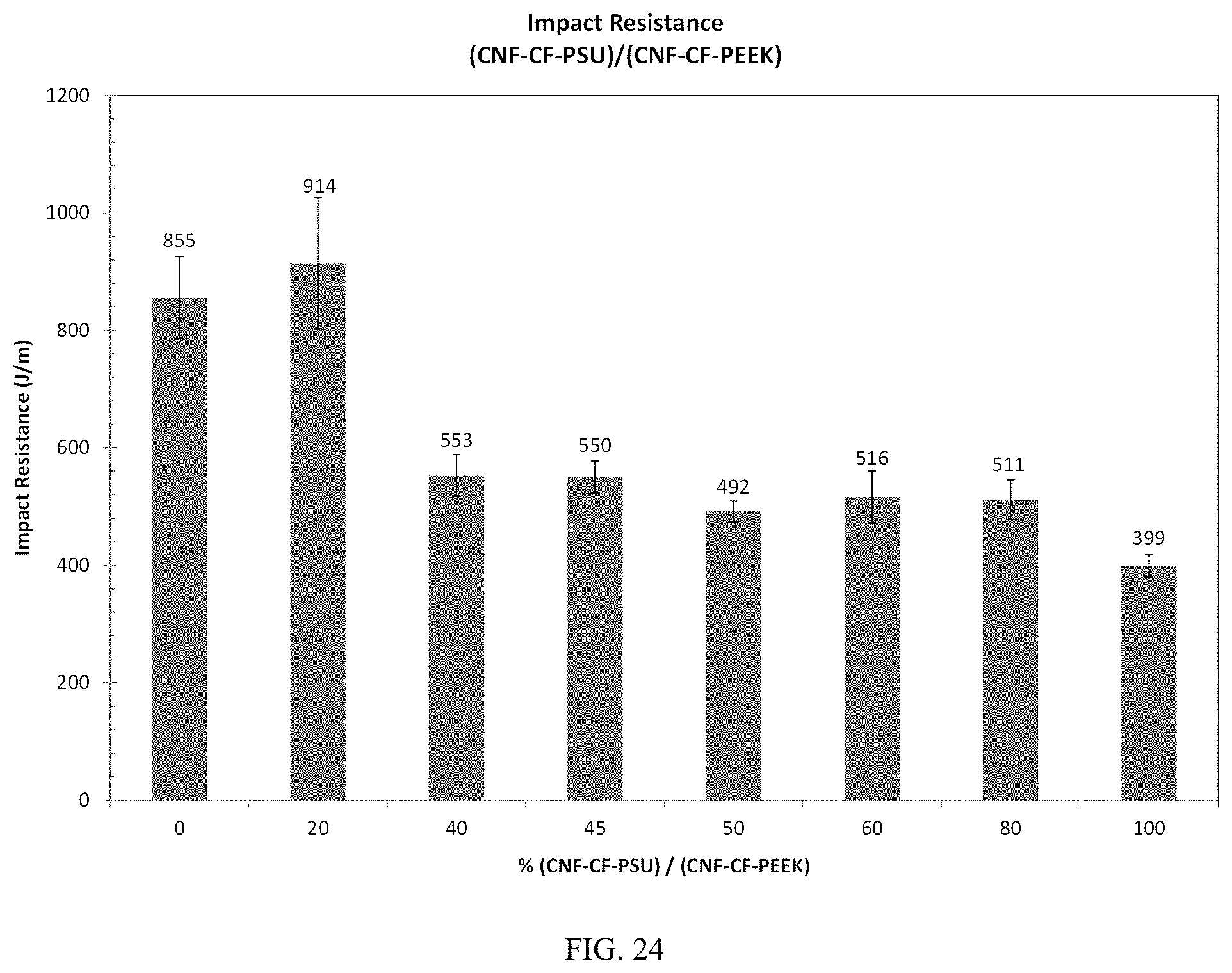
[0041] FIG. 24 shows Izod impact resistance of the (CNF-CF-PSU)/(CNF-CF-PEEK) composite IMPB as a function of wt % (CNF-CF-PSU) in (CNF-CF-PEEK).
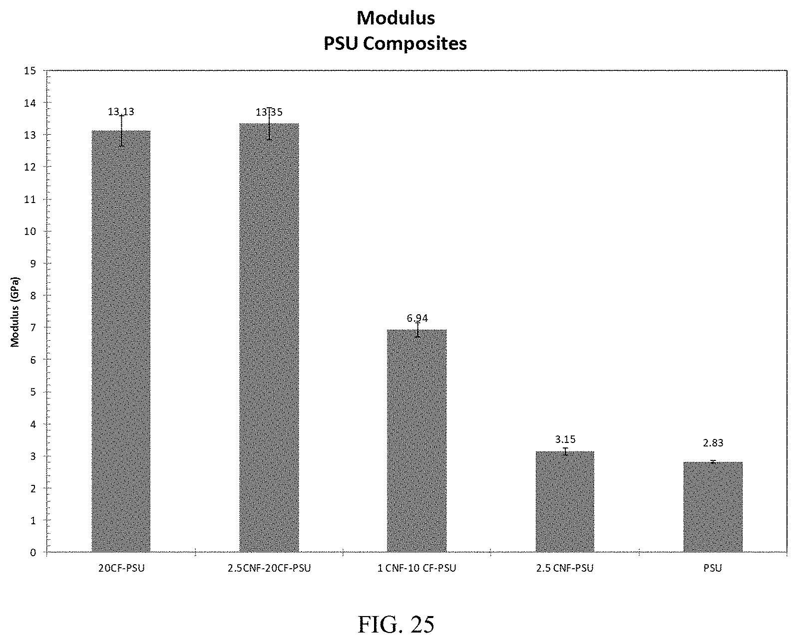
[0042] FIG. 25 shows tensile modulus for PSU and PSU composites.
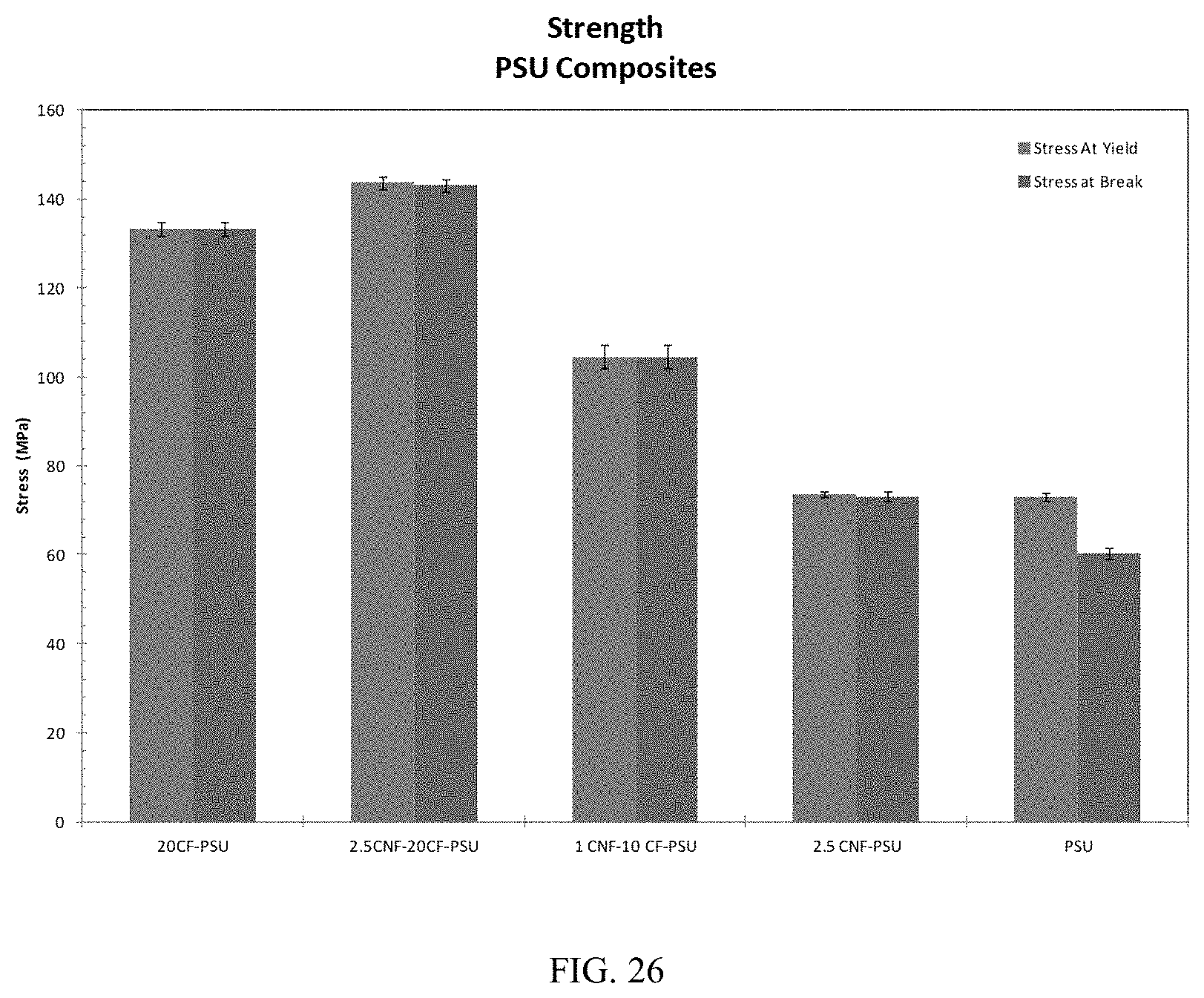
[0043] FIG. 26 shows tensile stress at yield and break for PSU and PSU composites.
[0044] FIG. 27 shows tensile % strain at yield for PSU and PSU composites.
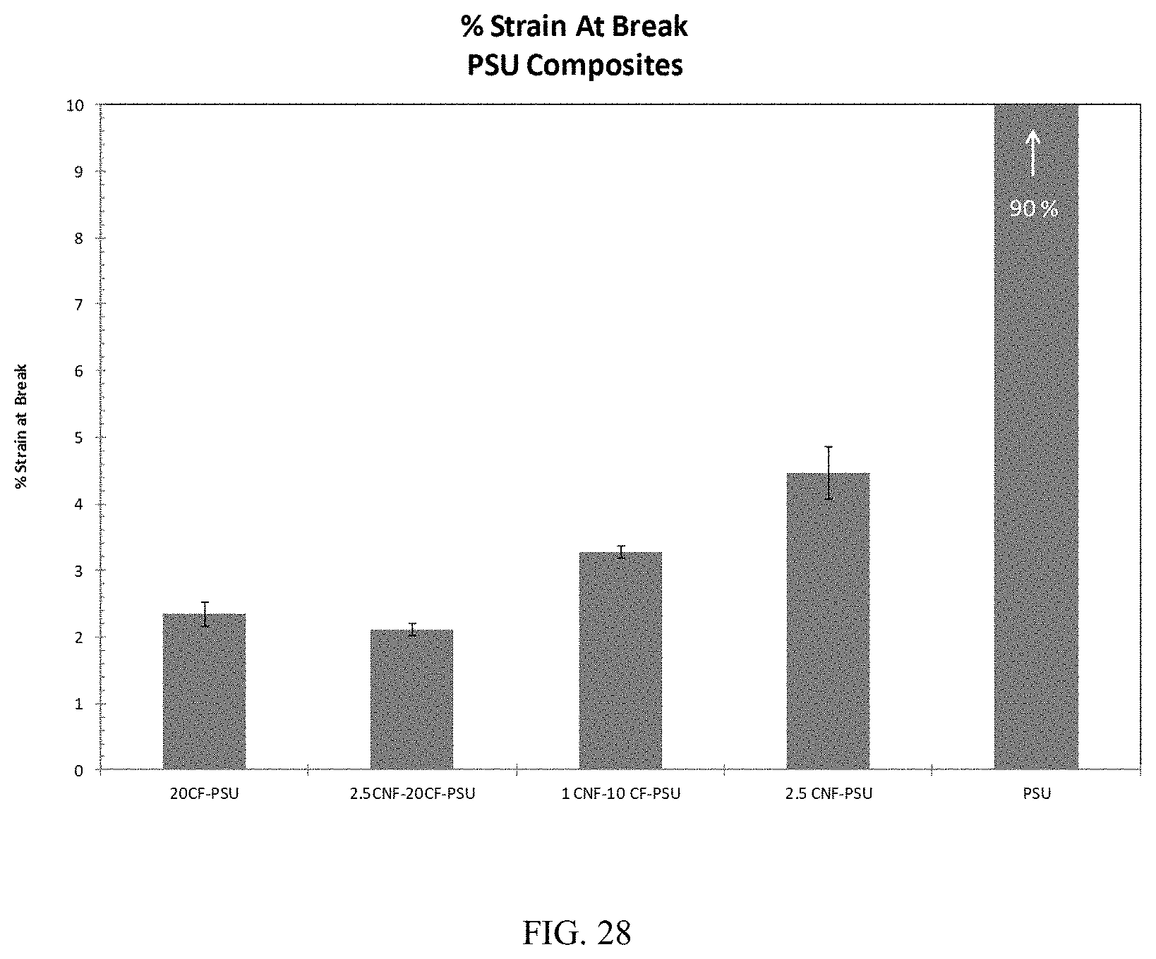
[0045] FIG. 28 shows tensile % strain at break for PSU and PSU composites.
DETAILED DESCRIPTION OF EMBODIMENTS
[0046] As disclosed herein, a number of ranges of values are provided. It is understood that each intervening value, to the tenth of the unit of the lower limit, unless the context clearly dictates otherwise, between the upper and lower limits of that range is also specifically disclosed. Each smaller range between any stated value or intervening value in a stated range and any other stated or intervening value in that stated range is encompassed within the invention. The upper and lower limits of these smaller ranges may independently be included or excluded in the range, and each range where either, neither, or both limits are included in the smaller ranges is also encompassed within the invention, subject to any specifically excluded limit in the stated range. Where the stated range includes one or both of the limits, ranges excluding either or both of those included limits are also included in the invention. The term "about" generally refers to plus or minus 10% of the indicated number. For example, "about 10%" may indicate a range of 9% to 11%, and "about 20" may mean from 18 to 22. Other meanings of "about" may be apparent from the context, such as rounding off, so, for example "about 1" may also mean from 0.5 to 1.4. Similarly, "about 0.2" may encompass the value 0.22.
[0047] One aspect of the invention is directed to a co-continuous immiscible polymer blend of a polysulfone and a polyaryletherketone reinforced with a carbon fiber. The polysulfone can have the structure
##STR00003##
The polyaryletherketone can be polyetheretherketone (PEEK), having the structure
##STR00004##
[0048] PEEK is a semi-crystalline, high temperature polyaryl etherketone and is processed at 360.degree. C. PSU is an amorphous, high temperature polymer and is also processed at 360.degree. C. PSU was targeted as the second polymer based on the high processing temperature restriction and its viscosity, which is lower than PEEK. In one embodiment, fiber self-alignment occurs during processing of the PSU/PEEK IMPB when the PSU phase is reinforced with CF and/or CNF prior to processing with PEEK. This provides enhanced mechanical and electrical properties over PEEK alone. In a further embodiment, the PEEK phase is also reinforced with CNF and/or CF and then processed with CNF and/or CF reinforced PSU. Other potential reinforcing agents include graphene, fiberglass (FG), natural fibers (NF), etc.
[0049] The carbon fiber can be selected from the group consisting of chopped carbon microfiber (CF), carbon nanofiber (CNF) and mixtures thereof. The amount of the polysulfone in the polyaryletherketone can range from about 20% to about 50% by weight, or from about 30% to about 50% by weight, or from about 40% to about 50% by weight, or the amount of the polysulfone in the polyaryletherketone can be about 45% by weight.
[0050] The amount of carbon microfiber present in the co-continuous immiscible polymer blend can range from about 5% to about 30% by weight, or about 10% to about 30%, or about 15% to about 25% by weight, or the amount of carbon microfiber present in the co-continuous immiscible polymer blend can be about 20% by weight. The amount of carbon nanofiber in the co-continuous immiscible polymer blend can range from about 0.5% to about 5% by weight, or about 1% to about 4% by weight, or about 2% to about 3%, or the amount of carbon nanofiber in the co-continuous immiscible polymer blend can be about 2.5% by weight. Further, the carbon nanofiber can be present in an amount from about 0.5% to about 2%, or about 1% to about 2% by weight together with carbon microfiber in an amount from about 5% to about 15%, or about 7% to about 13% by weight. The carbon nanofiber can be present in an amount of about 1% by weight together with carbon microfiber in an amount of about 10% by weight.
[0051] Another aspect of the invention is directed to a method of preparing a co-continuous immiscible polymer blend of a polysulfone and a polyaryletherketone reinforced with a carbon fiber, comprising the steps of a) preparing a carbon fiber-reinforced polysulfone, containing a reinforcing amount of carbon microfiber, carbon nanofiber, or a mixture thereof, and b) blending the carbon fiber-reinforced polysulfone with a polyaryletherketone, optionally reinforced with a reinforcing amount of carbon microfiber, carbon nanofiber, or a mixture thereof, in a blend ratio where the viscosity ratio of the components is equivalent to the composition ratio at constant processing temperature and shear rate.
[0052] Compounding may be performed in a batch mixer or extruder that imparts repetitive high shear rates, elongational flow and distributive mixing. Longer mixing times provide enhanced nano-morphology of the immiscible polymer blend. Furthermore, the morphological properties are tunable by modification of the mixing process. In one embodiment, the shear rate is between about 150 and about 950 s.sup.-1. In another embodiment, the shear rate is between about 250 and about 750 s.sup.-1. In one embodiment the mixing is performed using a single screw extruder that includes one or more mixing elements that impart uniform shear flow in combination with extensional and distributive mixing.
EXAMPLES
Example 1
[0053] An immiscible polymer blend of PSU/PEEK was processed and thermal, mechanical, and morphological properties investigated. Morphology analysis shows two very fine, distinct phases, indicating very good mixing during processing. The benefits of adding PSU to form a PSU/PEEK immiscible polymer blend include, (1) mechanical property enhancement in impact resistance and tensile % strain to yield, (2) processing aid, (3) cost reduction and (4) potential for self-alignment of carbon fibers and nanofibers within the total PEEK composite.
[0054] Examples of the thermoplastic resins and carbon fiber reinforcements used in the following examples are listed in Table 1.
TABLE-US-00001 TABLE 1 Materials Cost Name $/lb Product Vendor Description PEEK 46 KT-820 NT Solvay Advanced Semi- Polymers crystalline thermoplastic PSU 17 Udel P-1700 NT 11 Solvay Advanced Amorphous Polymers thermoplastic CNF 239 19-XT-LHT Pyrograf Nano-scale Products reinforcement CF 15 A HT C723 6 mm Toho Tenax Micro-scale America reinforcement
[0055] The processing equipment employed included, a Negri Boss V55-200 Injection Molding machine disclosed in U.S. Pat. No. 9,533,432, the disclosure of which is incorporated herein by reference, and a Randcastle single screw extruder (SSE) with multiple AFEM elements used for pre-compounding CNF and/or CF into the PSU phase. Prior to each processing step, PSU, PSU composites, PEEK and PEEK composites were dried at about 160.degree. C. for more than 12 hours.
[0056] The PSU/PEEK samples were dry-blended and directly injection molded. The molder was operated at 100 RPMs, which imparts a maximum shear rate of 315 s.sup.-1. The viscosity of PSU and PEEK at a temperature and shear rate of 360.degree. C. and 315 s.sup.-1 is 619.9 and 750.4 Pa-s, respectively. The dual phase, co-continuous structure is predicted to occur when the viscosity ratio of the components is equivalent to the composition ratio at a constant processing temperature and shear rate. The co-continuous region of the PSU/PEEK IMPB is predicted to occur at 45/55% PSU/PEEK. Thus, the PSU/PEEK IMPB was prepared at 0, 20, 40, 45, 50, 60, 80, and 100 weight % PSU in PEEK.
[0057] CNF-PSU, CF-PSU, and CNF-CF-PSU were melt-blended using the SSE, ground, dry-blended with PEEK, and injection molded at 0, 20, 40, 45, 50, 60, 80, and 100 weight % PSU composite in PEEK. The SSE was operated at 180 RPM and 342.degree. C. while preparing CNF, CF, and CNF-CF/PSU composites.
[0058] The CNF-CF-PEEK composite was prepared in two processing steps. First, 20% CF was melt-blended with PEEK using Randcastle SSE at 180 RPM and 360.degree. C. Second, 2.5% CNF was melt-blended with the 20CF-PEEK composite using the injection molding machine at 100 RPM and 360.degree. C. In this case, the injection molding machine was operated as an extruder to produce extrudate for grinding.
[0059] Representative materials systems investigated for this invention are listed in Table 2. The composition ratios were the same for each composite at 0, 20, 40, 45, 50, 60, 80, and 100 weight % of the PSU or PSU reinforced composite within PEEK or the PEEK composite.
TABLE-US-00002 TABLE 2 Exemplary materials systems No. Sample Name Description 1 PSU/PEEK Immiscible polymer blend of PSU and PEEK 2 PSU Composites PSU reinforced with CNF, CF, or CNF + CF 3 (CNF-PSU)/PEEK (2.5% CNF reinforced PSU)/PEEK 4 (CF-PSU)/PEEK (20% CF reinforced PSU)/PEEK 5 (CNF-CF-PSU)/PEEK (1% CNF and 10% CF reinforced PSU)/PEEK 6 (CNF-CF-PSU)/ (2.5% CNF and 20% CF reinforced (CNF-CF-PEEK) PSU)/(2.5% CNF and 20% CF reinforced PEEK)
Example 2. Characterization of IMPBs
[0060] The thermal and mechanical properties, as well as the morphological structure of the PSU/PEEK IMPB were determined. The thermal properties were characterized using a TA Instruments Q1000 DSC operated in standard heat/cool/reheat mode over a temperature range of 20-400.degree. C. at 10.degree. C./min. The mechanical properties were determined in uniaxial tension using a MTS Q Test/25 Universal Testing Machine, according to ASTM D638. The notched Izod impact resistance was determined using an Instron Dynatup POE 2000 Impact Tester, according to ASTM D256. The average impact velocity was 3.46 m/s. Impact resistance is calculated as the total energy absorbed upon impact divided by the specimen thickness (approximately 3.3 mm). The morphology analysis was completed using a Zeiss Field Emission Scanning Electron Microscope (FESEM) on specimens fractured at liquid nitrogen temperatures with a 5-6 nm gold coating applied to the fracture surface. The fracture surface is perpendicular to the extrusion direction.
Example 3. PSU Reinforced with CNF and CF
[0061] The carbon reinforced PSU composites were melt-blended using a Randcastle single screw extruder of Example 2 followed by injection molding, using the Negri Bossi injection molding machine and are listed in Table 3. The 2.5 CNF-20CF-PSU composite was achieved slightly differently than the others. The first melt-blending step using the Randcastle single screw extruder incorporated either the 2.5 CNF into the PSU or the 20 CF into the PSU, followed by a second processing step using the injection molding machine to add 20 CF to 2.5CNF-PSU or 2.5CNF to 20CF-PSU. All percentages were measured as weight percentages. Tensile and impact specimens were molded and tested according to ASTM D638 and D256, respectively. The tensile modulus, strength at yield and break, % strain at yield, and % strain at break appear in FIG. 25, FIG. 26, FIG. 27 and FIG. 28, respectively.
TABLE-US-00003 TABLE 3 Description of the carbon-reinforced PSU composites Label Description 2OCF-PSU 20% CF melt-blended with 80% PSU 2.5CNF-10CF-PSU 2.5% CNF and 10% CF melt-blended with 77.5% PSU 1CNF-10CF-PSU 1% CNF and 10% CNF melt-blended with 89% PSU 2.5CNF-PSU 2.5% CNF melt-blended with 87.5% PSU
[0062] The specific modulus and strength of aluminum 6061 is 25.9 GPa and 115 MPa, respectively. The specific yield strength, fracture strength, and modulus for these PSU composites are shown in Table 4. For the 20CF-PSU composite, the specific strength is over 100 MPa, and the specific modulus is almost 10 GPa.
TABLE-US-00004 TABLE 4 Specific tensile properties of PSU composites Composite or Specific Yield Specific Fracture Specific Element Strength (MPa) Strength (MPa) Modulus (GPa) Aluminum 6061 115 (ultimate) 25 20CF-PSU 101 101 9.9 2.5CNF-10CF-PSU 102 102 9.5 1CNF-10CF-PSU 81 81 5.4 2.5CNF 55 55 2.4 PSU 59 49 2.3
Results
Tensile Properties
[0063] PSU/PEEK
[0064] The mechanical properties in uniaxial tension were determined for all compositions of the PSU/PEEK IMPB. The stress-strain curves rise quickly to a peak and yield between 4% and 5% strain, after which, the stress decreases dramatically, plateaus, and then rises again. The average modulus per PSU/PEEK composition is displayed in FIG. 1. The stress at yield and stress at break per PSU/PEEK composition is displayed in FIG. 2. The % strain at peak and % strain at break are displayed in FIG. 3 and FIG. 4, respectively.
[0065] (CNF-PSU)/PEEK
[0066] The mechanical properties in uniaxial tension were determined for all compositions of the (CNF-PSU)/PEEK composite. The stress-strain curves rise quickly to a peak and yield between 4% and 5% strain. After yielding for 0%, 20%, and 40% (CNF-PSU) in PEEK, the stress decreases dramatically and plateaus, and then rises again before fracturing at greater than 70% strain. After yielding for 45, 50, and 60% (CNF-PSU) in PEEK, the stress decreases dramatically and plateaus before fracture between 40-65% strain. After yielding for 80% and 100% (CNF-PSU) in PEEK, the stress decreases dramatically and fracture occurs at less than 5% strain. The average modulus per (CNF-PSU)/PEEK composition is displayed in FIG. 5. The stress at yield and stress at break per (CNF-PSU)/PEEK composition are displayed in FIG. 6. The % strain at peak and % strain at break are displayed in FIG. 7 and FIG. 8, respectively.
[0067] (CF-PSU)/PEEK
[0068] The mechanical properties in uniaxial tension were determined for all compositions of the (CF-PSU)/PEEK composite. The stress-strain curves of the 20/80% (CNF-PSU)/PEEK sample behave similarly to the 100% PEEK sample but does fracture under 60% strain. For the remaining compositions, the stress-strain curves rise quickly to a peak and fracture at less than 5% strain. The average modulus per (CF-PSU)/PEEK composition is displayed in FIG. 9. The stress at yield and stress at break per (CF-PSU)/PEEK composition are displayed in FIG. 10. The % strain at peak and % strain at break are displayed in FIG. 11 and FIG. 12, respectively.
[0069] (CNF-CF-PSU)/PEEK
[0070] The mechanical properties in uniaxial tension were determined for all compositions of the (CNF-CF-PSU)/PEEK composite. The stress-strain curves of the 20/80% (CNF-CF-PSU)/PEEK sample behave similarly to the 100% PEEK sample but does fracture under 50% strain. The 100% (CNF-CF-PSU) sample attains the highest strength value but fractures at 3.3% strain. The remaining compositions follow the stress-strain behavior of PEEK, except that they fracture between 3.4-14% strain. The average modulus per (CNF-CF-PSU)/PEEK composition is displayed in FIG. 13. The stress at yield and stress at break per (CNF-CF-PSU)/PEEK composition are displayed in FIG. 14. The % strain at peak and % strain at break are displayed in FIG. 15 and FIG. 16, respectively.
[0071] (CNF-CF-PSU)/(CNF-CF-PEEK)
[0072] The mechanical properties in uniaxial tension were determined for all compositions of the (CNF-CF-PSU)/(CNF-CF-PEEK) composite. The stress-strain curves rise quickly to between 150 and 160 MPa and fracture between 2.2% and 3% strain. The average modulus per (CNF-CF-PSU)/(CNF-CF-PEEK) composition is displayed in FIG. 17. The stress at yield and stress at break per (CNF-CF-PSU)/(CNF-CF-PEEK) composition are displayed in FIG. 18. The % strain at break is displayed in FIG. 19.
Impact Properties
[0073] PSU/PEEK
[0074] The Izod impact resistance was determined for all compositions of the PSU/PEEK IMPB and is displayed in FIG. 20. All of the reported specimens experienced a complete break (C). The impact resistance of PEEK is 385 J/m. With increasing PSU content, the impact resistance increases to a maximum (507 J/m) at the dual phase, co-continuous structure of 45/55 wt % PSU/PEEK. This is attributed to the fine morphology of PSU and PEEK forming an interpenetra-ting network and large amount of interfacial area. The crack loses energy as it attempts to propa-gate through a tortuous path of PSU and PEEK domains, as well as a high concentration of PSU-PEEK interfaces. After the phase inversion in which PSU becomes the primary matrix, the impact resistance decreases toward the PSU impact resistance value of 166 J/m. Please note that the impact resistance for neat PEEK and PSU are higher than reported by the supplier, Solvay Advanced Polymers, as 91 J/m and 69 J/m, respectively. This is attributed to the unique, one-step processing method that provides high compounding and part fabrication in one processing step. The geometry of the mixing elements enables elongational mixing to produce an almost pure shear mixing environment that has an effect on even a neat polymer.
[0075] (CNF-PSU)/PEEK
[0076] The Izod impact resistance was determined for all compositions of the (CNF-PSU)/PEEK composite IMPB and is displayed in FIG. 21. The reported specimens resulted in a complete break (C). The impact resistance of PEEK is 385 J/m. With increasing (CNF-PSU) content, the impact resistance increases to a maximum (415 J/m) at 50/50 wt % (CNF-PSU)/PEEK. The dual-phase, co-continuous morphology may have shifted to the 50/50% composition due to the introduction of CNF in the PSU phase. After the phase inversion in which (CNF-PSU) becomes the primary matrix, the impact resistance decreases to 210 J/m.
[0077] (CF-PSU)/PEEK
[0078] The Izod impact resistance was determined for all compositions of the (CF-PSU)/PEEK composite IMPB and is displayed in FIG. 22. All of the reported specimens experienced a complete break (C). The impact resistance of PEEK is 385 J/m. With increasing (CF-PSU) content, the impact resistance increases to a maximum (469 J/m) at 40/60 wt % PSU/PEEK. After the phase inversion in which (CF-PSU) becomes the primary matrix, the impact resistance decreases toward the (CNF-PSU) impact resistance value of 379 J/m. Note that the impact resistance of neat PSU is much lower than (CNF-PSU) at only 166 J/m.
[0079] (CNF-CF-PSU)/PEEK
[0080] The Izod impact resistance was determined for all compositions of the (CNF-CF-PSU)/PEEK composite IMPB and is displayed in FIG. 23. All of the reported specimens experienced a complete break (C). The impact resistance of PEEK is 385 J/m. With increasing (CNF-CF-PSU) content, the impact resistance increases to a maximum of 466 J/m at 45/55 wt % PSU/PEEK. After the phase inversion in which (CNF-CF-PSU) becomes the primary matrix, the impact resistance decreases to 330 J/m. Note again that the impact resistance of neat PSU is 166 J/m, significantly lower than this PSU composite of (CNF-CF-PSU).
[0081] (CNF-CF-PSU)/(CNF-CF-PEEK)
[0082] The Izod impact resistance was determined for all compositions of the (CNF-CF-PSU)/(CNF-CF-PEEK) composite IMPB and is displayed in FIG. 24. All of the reported specimens experienced a complete break (C). The impact resistance of (CNF-CF-PEEK) composite is 855 J/m, while for PEEK the impact resistance is only 385 J/m. The impact resistance reaches a maximum value of 914 J/m at 20/80% (CNF-CF-PSU)/(CNF-CF-PEEK). For the remaining compositions, the impact resistance ranges between about 492-550 J/m. The minimum impact resistance of 399 J/m occurs at 100% (CNF-CF-PSU).
Morphological Structure
[0083] PSU/PEEK
[0084] The morphology of each PSUPEEK composition is revealed by electron micrograph images taken perpendicular to the machine or extrusion direction. Good mixing between the PSU and PEEK is evident by the fine structure and distribution of the two phases. PEEK is a semi-crystalline polymer and does attempt to increase density and shrink upon crystallization during cooling in the mold in a stepwise manner, while PSU is amorphous and does not attempt this type of step change in volume reduction.
[0085] At 20 wt % PSU in PEEK (a), PEEK is the primary matrix with well distributed nano-scale PSU fibers in intimate contact with the matrix. The PSU fiber diameter ranges from 200-500 nm. Most PSU fibers fractured, while others pulled out from the PEEK matrix and appear as holes. At 40 and 45 wt % PSU in PEEK (b) and (c), both phases appear to be continuous and intertwined with one another. The dual phase, co-continuous structure was predicted to occur at 45% PSU in PEEK. It is difficult to distinguish the PSU phase from the PEEK phase. Nevertheless, it is apparent that the PSU and PEEK domains are much less than 1,000 nm. Here, the PEEK phase attempts to shrink upon crystallization and applies hydrostatic like pressure on the PSU phase that inhibits the PEEK volume reduction. At 50 wt % PSU in PEEK (d), a phase inversion occurred, and PSU is the primary matrix with discrete PEEK fibers well distributed. At 50 and 60 wt % PSU in PEEK (d) and (e), the PEEK fiber diameter ranges from 200-1,000 nm, and the fibers appear to have shrunken away from the PSU matrix. This is due to the semi-crystalline nature of PEEK and the volume reduction that occurs upon crystallization during cooling from the melt. However, the 80 wt % PSU in PEEK micrograph shows intimate contact between the PEEK fiber and PSU matrix, which suggests lower crystallinity in the PEEK phase. Heat treating the blends may increase mechanical stress distribution between the phases.
[0086] The morphology of 100% (CNF-CF-PSU) and (CNF-CF-PEEK) is revealed by electron micrograph images taken at various scales and magnification. The images are taken perpendicular to the machine or extrusion direction. PEEK exhibits superior bonding with the carbon fiber, in comparison to PSU. The carbon nanofiber appears to bond with the polymers at the ends rather than along the length of the fiber. The two polymer phases are so well-mixed that they are nearly indistinguishable from one another.
Discussion
[0087] The addition of PSU to PEEK improves the impact resistance and % strain to yield while reducing costs. For example, by adding 20% PSU to PEEK, modulus, stress at yield and stress at break decrease only by 6, 2.3, and 6.7%, while impact resistance increases by 13.4%, compared to 100% PEEK. According to current resin prices for PSU ($17/1b) and PEEK ($46/1b) this would incur a savings of $5.80/1b. The addition of PSU to PEEK also acts like a processing aid and requires lower pressure during injection molding, making it easier to form complex shapes.
[0088] Furthermore, PSU has a lower viscosity than PEEK at the processing temperatures and provides a medium for self-alignment during processing of carbon fiber and carbon nanofibers within the total PSU/PEEK composite. This orientation effect will provide enhanced mechanical and electrical properties.
[0089] A summary of the impact resistance properties of the compositions of the invention is presented in the table below.
TABLE-US-00005 Impact Resistance (% PSU component in PEEK component) Composition 0% 20% 40% 45% 50% 60% 80% 100% PSU/PEEK 385 437 496 507 440 325 243 166 (CNF-PSU)/PEEK 385 350 400 322 415 332 226 210 (CF-PSU)/PEEK 385 457 469 418 429 443 405 379 (CNF-CF-PSU)/ 385 432 413 466 421 416 363 330 PEEK (CNF-CF-PSU)/ 855 914 553 550 492 516 511 399 (CNF-CF-PEEK)
[0090] It will be understood by those of skill in the art that numerous and various modifications can be made without departing from the spirit of the present invention. Therefore, it should be clearly understood that the various embodiments of the present invention described herein are illustrative only and are not intended to limit the scope of the present invention.
* * * * *
D00000
D00001
D00002
D00003
D00004
D00005
D00006

D00007
D00008

D00009

D00010

D00011

D00012
D00013

D00014
D00015

D00016

D00017

D00018

D00019
D00020

D00021

D00022
D00023

D00024
D00025
D00026
D00027

D00028
XML
uspto.report is an independent third-party trademark research tool that is not affiliated, endorsed, or sponsored by the United States Patent and Trademark Office (USPTO) or any other governmental organization. The information provided by uspto.report is based on publicly available data at the time of writing and is intended for informational purposes only.
While we strive to provide accurate and up-to-date information, we do not guarantee the accuracy, completeness, reliability, or suitability of the information displayed on this site. The use of this site is at your own risk. Any reliance you place on such information is therefore strictly at your own risk.
All official trademark data, including owner information, should be verified by visiting the official USPTO website at www.uspto.gov. This site is not intended to replace professional legal advice and should not be used as a substitute for consulting with a legal professional who is knowledgeable about trademark law.