Material Handling Basket
Greenblatt; Drew A. ; et al.
U.S. patent application number 16/406090 was filed with the patent office on 2020-11-12 for material handling basket. The applicant listed for this patent is Marlin Steel Wire Products, LLC. Invention is credited to Richard Bates, Drew A. Greenblatt, Andrew Montgomery.
| Application Number | 20200354105 16/406090 |
| Document ID | / |
| Family ID | 1000004098138 |
| Filed Date | 2020-11-12 |


View All Diagrams
| United States Patent Application | 20200354105 |
| Kind Code | A1 |
| Greenblatt; Drew A. ; et al. | November 12, 2020 |
MATERIAL HANDLING BASKET
Abstract
A material handling basket is provided comprising a base having two opposing pairs of substantially vertical outer walls. First and second sheet-metal dividers respectively extend between a first and second pair of the opposed vertical outer walls, and have a tab at each opposing end extending toward one of the walls of the first and second pairs of walls. Each of the walls of the first pair of walls has openings for accepting one of the tabs for positioning the first dividers relative to the respective wall; and each of the walls of the second pair of walls has openings for accepting one of the tabs for positioning the second dividers relative to the respective wall. Each of the tabs is rigidly joined to the respective opening to retain the first and second dividers between the first and second pairs of outer walls.
| Inventors: | Greenblatt; Drew A.; (Potomac, MD) ; Montgomery; Andrew; (Laurel, MD) ; Bates; Richard; (Baltimore, MD) | ||||||||||
| Applicant: |
|
||||||||||
|---|---|---|---|---|---|---|---|---|---|---|---|
| Family ID: | 1000004098138 | ||||||||||
| Appl. No.: | 16/406090 | ||||||||||
| Filed: | May 8, 2019 |
| Current U.S. Class: | 1/1 |
| Current CPC Class: | B65D 9/06 20130101; B65D 7/28 20130101; B65D 25/04 20130101; B65D 7/08 20130101; B65D 25/22 20130101; B65D 7/16 20130101; B65D 21/0212 20130101 |
| International Class: | B65D 6/04 20060101 B65D006/04; B65D 6/08 20060101 B65D006/08; B65D 25/22 20060101 B65D025/22; B65D 6/22 20060101 B65D006/22; B65D 21/02 20060101 B65D021/02; B65D 25/04 20060101 B65D025/04; B65D 6/02 20060101 B65D006/02 |
Claims
1. A basket comprising: a sheet-metal base having two opposing pairs of substantially vertical outer walls, each of the outer walls having a substantially horizontal bottom portion extending from a bottom of the wall towards its opposite wall, each of the walls joined to an adjacent wall to form a corner with the adjacent wall; and a first sheet-metal divider extending between a first pair of the opposed vertical outer walls; wherein the first divider has a tab at each opposing end extending toward one of the walls of the first pair of walls, and each of the walls of the first pair of walls has an opening for accepting one of the tabs for positioning the first divider relative to the respective wall; and wherein each of the tabs is rigidly joined to the respective opening to retain the first divider between the first pair of outer walls.
2. The basket of claim 1, comprising a second sheet-metal divider extending between a second pair of the opposed vertical outer walls; wherein the second divider has a tab at each opposing end extending toward one of the walls of the second pair of walls, and each of the walls of the second pair of walls has an opening for accepting one of the tabs for positioning the second divider relative to the respective wall; wherein each of the tabs is rigidly joined to the respective opening to retain the second divider between the second pair of outer walls; and wherein at least one of the first and second dividers has a slot for engaging the other one of the first and second dividers when the first and second dividers are positioned relative to the first and second pairs of outer walls.
3. The basket of claim 2, comprising a plurality of the first dividers and a plurality of the second dividers, the pluralities of first and second dividers each having slots for engaging each other such that the pluralities of first and second dividers can be positioned relative to each other to form a grid having a plurality of intersections; wherein each wall of the first pair of outer walls has openings for accepting the tabs of respective ones of the plurality of first dividers, and each wall of the second pair of outer walls has openings for accepting the tabs of respective ones of the plurality of second dividers, and each of the first and second dividers are respectively retained between the first and second pairs of outer walls.
4. The basket of claim 1, wherein each of the corners of the base comprises: a corner tab extending from one of the vertical outer walls and contacting an adjacent outer wall; and a weld joint or a rivet for rigidly attaching the corner tab to the adjacent outer wall.
5. The basket of claim 3, wherein each of the intersections of the grid comprises a first extended portion of one of the first dividers and a second extended portion of one of the second dividers, the first and second extended portions together forming a prong which extends upwardly from a bottom of the basket; wherein the prong has a plurality of outer surfaces for engaging one or more inner surfaces of a workpiece to be supported in the basket by the prong, the prong outer surfaces cooperating with each other and with the one or more inner surfaces of the workpiece to hold the workpiece in a predetermined position in the basket such that the workpiece is substantially stationary relative to the basket.
6. The basket of claim 1, wherein each of the vertical outer walls comprises a plurality of window openings.
7. The basket of claim 6, wherein one or more of the plurality of openings in each of the outer walls comprises a finger hole for allowing a user to insert a finger to lift the basket.
8. The basket of claim 1, wherein each outer wall of one of the opposing pairs of vertical outer walls comprises a hoist arm for engaging an overhead lifting device for lifting the basket.
9. The basket of claim 1, wherein each wall of one of the pairs of vertical outer walls comprises a vertically-extending stacking tab at a top of the wall, and a stacking slot at a bottom of the wall, for engaging a corresponding stacking slot or stacking tab, respectively, of a second basket, for stacking the basket and the second basket.
10. The basket of claim 3, wherein the base further comprises a bottom member extending between the horizontal bottom portions; and wherein the first dividers and the second dividers each have a bottom tab extending towards the bottom member, and the bottom member has slots for engaging the bottom tabs of the first and second dividers.
11. The basket of claim 10, wherein the bottom member has openings, the basket further comprising a mesh member attached to the bottom member and extending over the openings.
12. The basket of claim 3, wherein each of the tabs of each of the first and second dividers is joined to the respective opening of each of the outer walls by a weld, to respectively retain the first and second dividers between the first and second pairs of outer walls.
13. The basket of claim 5, further comprising a lid removably attachable to a top of each of the vertical outer walls, the lid comprising: a sheet-metal lid base having two opposing pairs of substantially vertical outer lid walls corresponding to the two opposing pairs of outer walls of the basket base, each of the lid walls joined to an adjacent lid wall to form a corner with the adjacent lid wall; and a lid bottom, extending between the outer lid walls, for constraining movement of each of the workpieces supported by each of the prongs when the lid is attached to the top of the outer walls of the basket.
14. The basket of claim 13, wherein each wall of one of the pairs of vertical outer walls of the basket comprises a vertically-extending stacking tab at the top of the wall, and the lid base has a lid slot at a bottom of each wall of a corresponding one of the pairs of vertical outer lid walls for engaging the corresponding stacking tab, for attaching the lid to the basket.
15. The basket of claim 14, wherein each wall of one of the pairs of vertical outer walls of the basket further comprises a stacking slot at a bottom of the wall, for engaging a corresponding stacking tab of an additional one of the baskets, for stacking the basket and the additional basket; wherein the outer lid walls have a height such that when the lid is attached to the basket, and the basket and one or more of the additional baskets are stacked, a total height of the stacked baskets and the lid is substantially equal to a predetermined total height.
16. The basket of claim 13, wherein the lid comprises first and second sheet-metal lid dividers respectively extending between first and second pairs of the opposed vertical outer lid walls; wherein each of the first and second lid dividers has a tab at each opposing end extending toward one of the lid walls of the first and second pairs of outer lid walls, and each of the lid walls of the first and second pairs of outer lid walls has an opening for accepting one of the tabs for positioning the first and second dividers relative to the respective lid walls; wherein each of the tabs is rigidly joined to the respective opening in one of the lid walls to retain the first and second dividers between the first and second pairs of outer walls; and wherein at least one of the first and second lid dividers has a slot for engaging the other one of the first and second lid dividers when the first and second lid dividers are positioned relative to the first and second pairs of outer lid walls.
17. The basket of claim 10, further comprising a sheet-metal lid attachable to a top of each of the vertical outer walls by at least one of a latch and a hinge; wherein the lid is for engaging the grid for constraining movement of workpieces held by the grid.
18. A method of manufacturing a basket, the method comprising: providing a sheet-metal base having two opposing pairs of substantially vertical outer walls, each of the outer walls having a substantially horizontal bottom portion extending from a bottom of the wall towards its opposite wall, each of the walls joined to an adjacent wall to form a corner with the adjacent wall; providing a plurality of first sheet-metal dividers for extension between a first pair of the opposed vertical outer walls, each of the first dividers having a tab at each opposing end; providing a plurality of second sheet-metal dividers for extension between a second pair of the opposed vertical outer walls, each of the second dividers having a tab at each opposing end; wherein the pluralities of first and second dividers each have slots for engaging each other, and each wall of the first pair of outer walls has openings for accepting the tabs of respective ones of the plurality of first dividers, and each wall of the second pair of outer walls has openings for accepting the tabs of respective ones of the plurality of second dividers; the method further comprising: engaging the slots of the pluralities of first and second dividers with each other to form a grid having a plurality of intersections; engaging each tab of the pluralities of first and second dividers with a corresponding opening in one of the walls of the first and second pairs of outer walls to position the first dividers and second dividers relative to the first and second pairs of outer walls; and rigidly joining each of the tabs to the corresponding opening to retain the first and second dividers between the first and second pairs of outer walls.
19. The method of claim 10, wherein providing the sheet-metal base comprises forming the horizontal bottom portion of each of the outer walls integrally with one of the outer walls.
20. A basket comprising a prong having a cruciform cross-section, the prong extending upwardly from a bottom of the basket; wherein the prong has a plurality of outer surfaces for engaging one or more inner surfaces of a workpiece to be supported in the basket by the prong, the prong outer surfaces cooperating with each other and with the one or more inner surfaces of the workpiece to hold the workpiece in a predetermined position in the basket such that the workpiece is substantially stationary relative to the basket.
Description
FIELD
[0001] Embodiments relate generally to material handling baskets and methods of manufacturing such baskets.
BACKGROUND
[0002] Material handling baskets are often used for holding workpieces (also referred to herein as "parts") during a manufacturing process. For example, a number of parts may be arranged in a two-dimensional array in a basket, each part in a predetermined position, so that a robotic pick and place gripper can automatically pick up the part. Conventional material handling baskets are typically made of metal wire that is welded together, with plastic supports called "prongs" attached to the metal wire for vertical support of parts at predetermined locations in the basket, so a robot gripper can pick up the part.
[0003] These conventional wire baskets have several important disadvantages. They have many welds and are made of many parts, especially when they have plastic prongs. This requires expensive fixturing for manufacturing the baskets, and also requires many manufacturing steps, resulting in high costs and manufacturing time. Additionally, the welds cause heat distortion and deformation, so the parts cannot be accurately located in the basket with the parallelism and perpendicularity required by precision robots and grippers. In particular, the plastic prongs tend not to support parts with consistent perpendicularity, and may allow parts to move and change position. This variation in perpendicularity prevents robotic pick and place grippers from picking up parts in their assigned space, causing the robots to crash. This means the manufacturing machines cannot be run at full speed, and require expensive personnel tending the robots to correct problems.
[0004] Another disadvantage is that the vertical outside supports or "ledges" typical of wire baskets can interfere with grippers due to their size and position. These basket structures encroach into useful space, effectively reducing the capacity of the baskets by acting as obstacles to the free movement of the robot grippers. In such cases, parts cannot be loaded onto prongs located next to the vertical supports of the basket, thereby reducing manufacturing efficiency.
[0005] There exists a need for a material handling basket that is simpler and less expensive to manufacture, can be manufactured with the proper precision, and holds parts with the accuracy needed by robotic grippers. There also exists a need for a basket that maximizes useful space for parts, and does not have supports and/or welds that encroach into the interior of the basket and interfere with grippers.
SUMMARY
[0006] One or more embodiments can include a material handling basket comprising a sheet-metal base having two opposing pairs of substantially vertical outer walls, each of the outer walls having a substantially horizontal bottom portion extending from a bottom of the wall towards its opposite wall, each of the walls joined to an adjacent wall to form a corner with the adjacent wall. A first sheet-metal divider extends between a first pair of the opposed vertical outer walls, and has a tab at each opposing end extending toward one of the walls of the first pair of walls. A second sheet-metal divider extends between a second pair of the opposed vertical outer walls, and has a tab at each opposing end extending toward one of the walls of the second pair of walls. Each of the walls of the first pair of walls has an opening for accepting one of the tabs for positioning the first divider relative to the respective wall; and each of the walls of the second pair of walls has an opening for accepting one of the tabs for positioning the second divider relative to the respective wall. Each of the tabs is rigidly joined to the respective opening to retain the first and second dividers between the first and second pairs of outer walls.
[0007] Embodiments further include a basket comprising a prong having a cruciform cross-section, the prong extending upwardly from a bottom of the basket. The prong has a plurality of outer surfaces for engaging one or more inner surfaces of a workpiece to be supported in the basket by the prong, the prong outer surfaces cooperating with each other and with the one or more inner surfaces of the workpiece to hold the workpiece in a predetermined position in the basket, such that the workpiece is substantially stationary relative to the basket.
[0008] Embodiments further comprise method of manufacturing a basket, the method comprising providing a sheet-metal base having two opposing pairs of substantially vertical outer walls, each of the outer walls having a substantially horizontal bottom portion extending from a bottom of the wall towards its opposite wall, each of the walls joined to an adjacent wall to form a corner with the adjacent wall. A plurality of first sheet-metal dividers is also provided for extension between a first pair of the opposed vertical outer walls, each of the first dividers having a tab at each opposing end. Additionally, a plurality of second sheet-metal dividers is provided for extension between a second pair of the opposed vertical outer walls, each of the second dividers having a tab at each opposing end. The pluralities of first and second dividers each have slots for engaging each other, and each wall of the first pair of outer walls has openings for accepting the tabs of respective ones of the plurality of first dividers, and each wall of the second pair of outer walls has openings for accepting the tabs of respective ones of the plurality of second dividers.
[0009] The method further comprises engaging the slots of the pluralities of first and second dividers with each other to form a grid having a plurality of intersections; engaging each tab of the pluralities of first and second dividers with a corresponding opening in one of the walls of the first and second pairs of outer walls to position the first dividers and second dividers relative to the first and second pairs of outer walls; and rigidly joining each of the tabs to the corresponding opening to retain the first and second dividers between the first and second pairs of outer walls.
[0010] Objects and advantages of embodiments of the disclosed subject matter will become apparent from the following description when considered in conjunction with the accompanying drawings.
BRIEF DESCRIPTION OF THE DRAWINGS
[0011] Embodiments will hereinafter be described in detail below with reference to the accompanying drawings, wherein like reference numerals represent like elements. The accompanying drawings have not necessarily been drawn to scale. Where applicable, some features may not be illustrated to assist in the description of underlying features.
[0012] FIG. 1A is a top perspective view of a material handling basket according to an embodiment of the present disclosure.
[0013] FIG. 1B is a top perspective view of a base of the basket of FIG. 1A.
[0014] FIGS. 1C and 1D are perspective views of dividers of the basket of FIG. 1A.
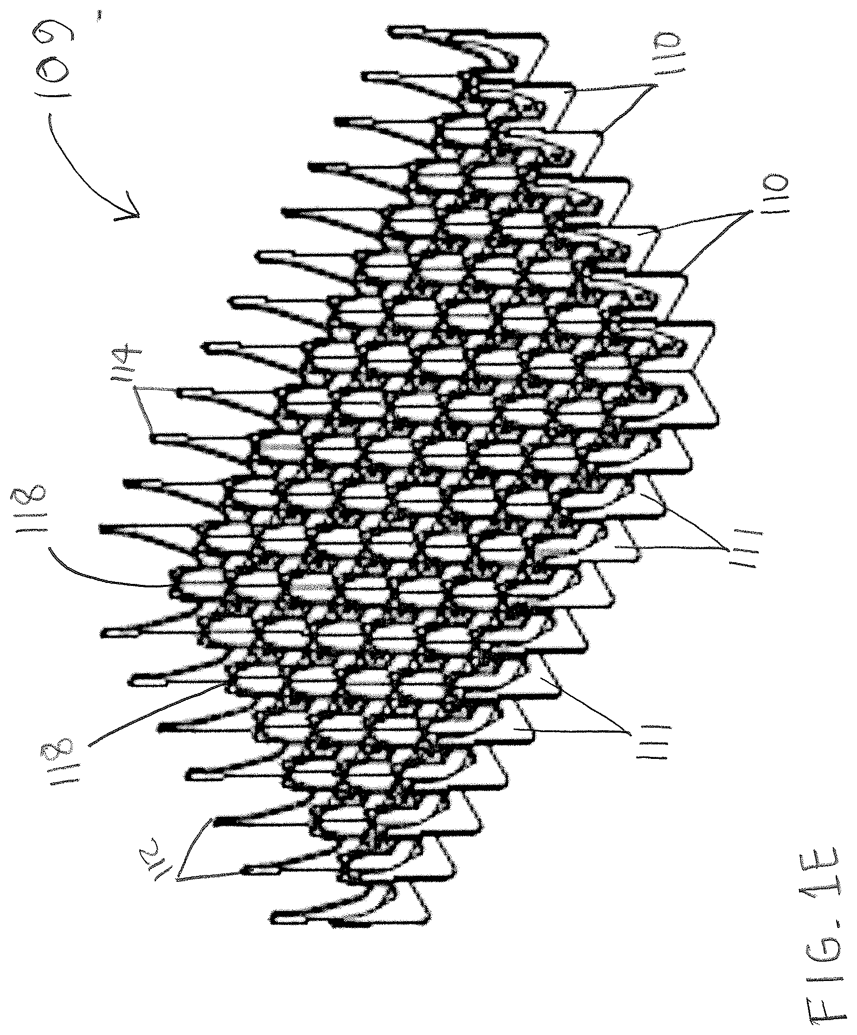
[0015] FIG. 1E is a top perspective view of a divider grid of the basket of FIG. 1A.
[0016] FIG. 1F is partial perspective view of the basket of FIG. 1A.
[0017] FIG. 1G is a front view of a prong of the basket of FIG. 1A.
[0018] FIG. 1H is a cross-sectional view of the prong of FIG. 1G supporting a workpiece.
[0019] FIG. 1I is a front perspective view of a lid for the basket of FIG. 1A according to an embodiment of the present disclosure.
[0020] FIG. 1J is a front view of a stack of three of the baskets of FIG. 1A and the lid of FIG. 1I.
[0021] FIG. 2A is a top perspective view of a material handling basket according to a further embodiment of the present disclosure.
[0022] FIG. 2B is a bottom perspective view of the basket of FIG. 2A.
[0023] FIG. 2C is a top perspective view of a divider grid of the basket of FIG. 2A.
[0024] FIG. 2D is top view of the basket of FIG. 2A.
[0025] FIG. 2E is top view of the basket of FIG. 2A holding workpieces.
[0026] FIG. 2F is cross-sectional front view of the basket of FIG. 2A holding workpieces.
[0027] FIG. 2G is a top perspective view of a stack of two of the baskets according to FIG. 2A.
[0028] FIG. 3A is top perspective view of a material handling basket according to another embodiment of the present disclosure.
[0029] FIG. 3B is a top view of the basket of FIG. 3A.
[0030] FIGS. 4A and 4B are top and bottom perspective views, respectively, of a material handling basket according to another embodiment of the present disclosure.
[0031] FIG. 5 is a flow chart of an exemplary method of manufacturing a material handling basket according to an embodiment of the present disclosure.
DETAILED DESCRIPTION
[0032] It should be understood that the principles described herein are not limited in application to the details of construction or the arrangement of components set forth in the following description or illustrated in the following drawings. The principles can be embodied in other embodiments and can be practiced or carried out in various ways. Also, it is to be understood that the phraseology and terminology used herein is for the purpose of description and should not be regarded as limiting.
[0033] Disclosed herein are material handling baskets for supporting a plurality of workpieces in an array, and methods for manufacturing such baskets. The disclosed baskets comprise a sheet metal base and dividers which snap together, thereby eliminating the need for fixturing during assembly. The base and dividers can be laser cut for improved tolerances, and welded and/or riveted together only on the exterior--not the interior or bottom--to reduce heat distortion and improve parallelism. In certain embodiments, the workpieces are supported in the disclosed basket on cruciform prongs formed by the dividers. The prongs are contoured to fit the workpieces so that they grip the workpieces, enabling the workpieces to rest on the prongs accurately and securely without falling off or moving, as disadvantageously occurs with conventional baskets. The "low profile" of the disclosed baskets' sheet metal construction, the precision of their construction, and the ability of their prongs to securely hold workpieces in the proper position, enable the disclosed baskets to increase manufacturing throughput when used in conjunction with robotic pick and place grippers and other such machines.
[0034] FIGS. 1A-1J illustrate an exemplary embodiment of a material handling basket according to the present disclosure. In this embodiment, a plurality of workpieces are held in predetermined positions in the basket by an array of prongs. Referring now to FIGS. 1A-E, a basket 100 comprises a sheet-metal base 101, such as a steel or aluminum base, having two opposing pairs of substantially vertical outer walls 102a, 102b, each of the outer walls 102a, b having a substantially horizontal bottom portion 103a, 103b extending from a bottom of the wall 102a,b towards its opposite wall 102a,b. Outer walls 102a,b are shown having different lengths such that the basket 100 has an overall rectangular shape. However, those of skill in the art will understand that outer walls 102a,b can have the same length if desired. In certain embodiments, base 101 is laser cut and deburred, and formed from a single flat sheet of metal, which is bent into the desired shape. Laser cutting for the base 101 as well as other parts of basket 100 is advantageous insofar as the basket 100 can be made to tighter tolerances than conventional wire baskets. Consequently, workpieces are held by basket 100 more consistently in the proper place.
[0035] Each of the walls 102a,b is joined to an adjacent wall 102a,b to form a corner 104 with the adjacent wall 102a,b. Each corner 105 has a corner tab 105 extending from one of the vertical outer walls (FIG. 1B shows corner tabs 105 extending from walls 102b) and contacting an adjacent outer wall 102a. A weld joint or a rivet 106 rigidly attaches the corner tab 105 to the adjacent outer wall 102a. The welds 106 can be; for example, conventional TIG or MIG welds or resistance spot welds that are close to being flush with the surface of the walls 102a, so they do not interfere with placement of the basket 100 in a machine. In the alternative, conventional rivets can be advantageously used to reduce distortions to the metal from welding heat, and to provide additional strength to the joints.
[0036] Each of the vertical outer walls 102a,b comprises a plurality of window openings 107. In certain embodiments, some of the plurality of openings in at least one pair of the outer walls 102a,b comprise finger holes 108 for allowing a user to insert a finger or fingers to lift the basket 100. In these embodiments, basket 100 does not need added handles that protrude and could obstruct robotic grippers that are typically used in conjunction with baskets 100 in a manufacturing context.
[0037] Referring particularly to FIGS. 1C-E, basket 100 further comprises a grid 109 of substantially perpendicular first sheet metal dividers 110 and second sheet metal dividers 111, all of which are laser cut and deburred prior to assembly. The first sheet-metal dividers 110 extend between a first pair of the opposed vertical outer walls 102a, and the second sheet-metal dividers 111 extend between a second pair of the opposed vertical outer walls 102b. A plurality of the first dividers 110 has a tab 112 at each opposing end extending toward one of the walls 102a of the first pair of walls, and each of the walls 102a of the first pair of walls has openings 113 each for accepting one of the tabs 112 for positioning the first dividers 110 relative to the respective walls 102a. Likewise, a plurality of the second dividers 111 each have a tab 114 at each opposing end extending toward one of the walls 102b of the second pair of walls, and each of the walls 102b of the second pair of walls has an opening 115 for accepting one of the tabs 114 for positioning the second dividers 111 relative to the respective walls 102b.
[0038] Additionally, each divider 110, 111 of the pluralities of first and second dividers has slots 116, 117 for engaging each other such that the first and second dividers 110, 111 can be positioned relative to each other to form the grid 109 having a plurality of intersections 118.
[0039] Each of the first divider tabs 112 is rigidly joined, as by a weld joint 119, to a respective opening 113 in one of the walls 102a to retain the first dividers 110 between the outer walls 102a. Likewise, each of the second divider tabs 114 is rigidly joined, as by a weld joint 120, to a respective opening 115 in one of the walls 102b to retain the second dividers 111 between the outer walls 102b. Because the disclosed basket 100 includes only a small number of welds, on exterior surfaces only and not on bottom or interior surfaces, heat distortion during the manufacturing process is reduced, and parallelism is improved versus conventional wire baskets.
[0040] In the present embodiment, each of the intersections 118 of the grid 109 comprises a first extended portion 121 of one of the first dividers 110 and a second extended portion 122 of one of the second dividers 111, the first and second extended portions 121, 122 together forming a prong 125 having a cruciform cross-section, as shown close-up in FIG. 1F. Prong 125 extends upwardly from a bottom of the basket 100. Basket 100 can hold an array of workpieces on respective prongs 125. Referring now to FIGS. 1G-H, prong 125 has a plurality of outer surfaces 126 for engaging one or more inner surfaces 127a of workpiece 127 to be supported in the basket 100 by the prong 125, the prong outer surfaces 126 cooperating with each other and with the one or more inner surfaces 127a of the workpiece 127 to hold the workpiece 127 in a predetermined position in the basket 100 such that the workpiece 127 is substantially stationary relative to the basket 100.
[0041] In certain embodiments, the top portions 126a prong outer surfaces 126 are contoured to fit the workpiece 127, advantageously resulting in reduced abrasion between the prong 125 and the workpiece 127, thereby avoiding marring and scratching of workpiece 127. Additionally, since the prongs 125 fit the workpieces 127, the workpieces 127 rest accurately and securely in the basket 100 without falling off the prongs 125. This advantageously eliminates the need for prongs having plastic tines, as in conventional material handling baskets, which are costly to make and install, and do not accurately align workpieces within the basket. Accurate placement and retention of workpieces 127 in basket 100 is crucial when basket 100 is to be used in conjunction with robotic grippers that pick up the workpieces 127.
[0042] The disclosed basket 100 comprises mostly flat metal outer and inner walls and surfaces, eliminating the wire supports and ledges of conventional baskets, which encroach into useful space and interfere with robotic grippers. The design of basket 100 enables robotic grippers to pick parts that are supported practically anywhere in the basket 100 (i.e., at all the intersections 118 of the grid 109), thereby improving utilization.
[0043] Each of the vertical outer walls 102a,b of the base 101 also comprises a vertically-extending stacking tab 130 at a top of the wall 102a,b, and a stacking slot 131 at a bottom of the wall 102a,b. As shown in FIG. 1A, stacking tab 130 and slot 131 are each for engaging a corresponding stacking slot 130 or stacking tab 131, respectively, of a second basket 100, for stacking the basket 100 and the second basket 100. Those of skill in the art will understand that additional baskets 100 can also be stacked, as depicted in FIG. 1J showing three stacked baskets 100. Since the stacking tabs and slots are integrated with the basket, they are sturdy and eliminate the need for welds and ledges of conventional wire baskets, which encroach into useful space and interfere with robot grippers.
[0044] Referring now to FIGS. 1I-J, the disclosed basket 100 of this embodiment can further comprise a removable lid 140 attachable to a top of each of the vertical outer walls 102a,b. Lid 140 comprises a sheet-metal lid base 141 having first and second opposing pairs of substantially vertical outer lid walls 142a, 142b corresponding to the two opposing pairs of outer walls 102a, 102b of the basket base 101, each of the lid walls 142a,b joined to an adjacent lid wall 142a,b to form a corner 143 with the adjacent lid wall 142a,b. Lid 140 also has a lid bottom 144 extending between the outer lid walls 142a,b. Lid bottom 144 is for constraining movement of each of the workpieces 127 supported by each of the prongs 125 when the lid 140 is attached to the top of the outer walls 102a,b of basket 100. This can be accomplished by the lid bottom 144 engaging the grid 109 of basket 100 or the workpieces 127. In the illustrated example, openings 145 are provided in the lid bottom 144 and engage workpieces 127. Thus, lid 140 will constrain workpieces 127 if they are flipped over; for example, in a parts washer.
[0045] In certain embodiments, the lid 140 comprises first and second sheet-metal lid dividers 146, 147 respectively extending between the first and second pairs of the opposed vertical outer lid walls 142a,b. Each of the first and second lid dividers 146, 147 has a tab 148, 149 at each opposing end extending toward one of the lid walls 142a,b of the first and second pairs of outer lid walls, and each of the lid walls 142a, 142b has an opening 150, 151 for accepting one of the tabs 148, 149 for positioning the first and second dividers 146, 147 relative to the respective lid walls 142a,b. Each of the tabs 148, 149 is rigidly joined, as by welding, to the respective opening 150, 151 in one of the lid walls 142a,b to retain the first and second dividers 146, 147 between the first and second pairs of outer walls 142a,b. At least one of the first and second lid dividers 146, 147 has a slot (not shown) for engaging the other one of the first and second lid dividers 146, 147 when the first and second lid dividers 146, 147 are positioned relative to the first and second pairs of outer lid walls 142a,b.
[0046] As discussed herein above and shown in FIG. 1A, each of the vertical outer walls 102a,b of the basket 100 comprises a vertically-extending stacking tab 130 at the top of the wall. The lid base 141 has a corresponding lid slot 146 at a bottom of each of the vertical outer lid walls 142a,b for engaging a corresponding basket stacking tab 130, for attaching the lid 140 to the basket 100. FIG. 1J shows lid 140 attached to a basket 100.
[0047] As also discussed in detail herein above, a number of baskets 100 can be stacked. As shown in FIG. 1J, the outer lid walls 142a,b have a height h such that when the lid 140 is attached to a basket 100, and the basket 100 and one or more additional baskets 100 are stacked, a total height H of the stacked baskets 100 and the lid 140 is substantially equal to a predetermined total height. Thus, the lid height h can be selected to adjust the total height H so the stack fits inside a cavity, such as a cavity of a parts washer.
[0048] An alternative embodiment of the disclosed basket will now be described with reference to FIGS. 2A-2G. In this embodiment, the dividers do not have extended portions that form cruciform prongs to hold workpieces. Rather, the dividers form compartments to hold workpieces, along with a bottom portion of the basket base. Otherwise, the basket of this embodiment is similar or identical in most major respects to the basket 100 of the embodiment of FIGS. 1A-E described herein above.
[0049] As shown in FIGS. 2A-D, a basket 200 comprises a sheet-metal base 201, such as a steel or aluminum base, having two opposing pairs of substantially vertical outer walls 202a, 202b, each of the outer walls 202a,b having a substantially horizontal bottom portion 203a, 203b extending from a bottom of the wall 202a,b towards its opposite wall 202a,b. Base 201 also has a bottom member 203c extending between the horizontal bottom portions 203a,b. Bottom member 203c can be formed integrally with the base 201 as shown in FIGS. 2B. Outer walls 202a,b are shown having different lengths such that the basket 200 has an overall rectangular shape. However, those of skill in the art will understand that outer walls 202a,b can have the same length if desired. In certain embodiments, base 201 is laser cut and deburred, and formed from a single flat sheet of metal, which is bent into the desired shape. Laser cutting for all the base 201 as well as other parts of basket 200 is advantageous insofar as the basket 200 can be made to tighter tolerances than conventional wire baskets. Consequently, workpieces are held by basket 200 more consistently in the proper place.
[0050] Each of the walls 202a,b is joined to an adjacent wall 202a,b to form a corner 204 with the adjacent wall 202a,b. Each corner 205 has a corner tab 205 extending from one of the vertical outer walls and contacting an adjacent outer wall (in FIGS. 2A-B corner tabs 205 extend from walls 202a). Rivets 206 or welds, which are close to being flush with the surface of the walls 202a, rigidly attach the corner tab 205 to the adjacent outer wall 202a. Conventional rivets 206 can be advantageously used to reduce distortions to the metal from welding heat, and to provide additional strength to the joints. Each of the vertical outer walls 202a,b and the bottom member 203c comprises a plurality of window openings 207.
[0051] Referring in particular to FIG. 2C, basket 200 further comprises a grid 209 of substantially perpendicular first sheet metal dividers 210 and second sheet metal dividers 211, all of which are laser cut and deburred prior to assembly. The first sheet-metal dividers 210 extend between a first pair of the opposed vertical outer walls 202a, and the second sheet-metal dividers 211 extend between a second pair of the opposed vertical outer walls 202b. A plurality of the first dividers 210 has a tab 212 at each opposing end extending toward one of the walls 202a of the first pair of walls, and each of the walls 202a of the first pair of walls has openings 213, each for accepting one of the tabs 212 for positioning the first dividers 210 relative to the respective walls 202a. Likewise, a plurality of the second dividers 211 each have a tab 214 at each opposing end extending toward one of the walls 202b of the second pair of walls, and each of the walls 202b of the second pair of walls has an opening 215 for accepting one of the tabs 214 for positioning the second dividers 211 relative to the respective walls 202b.
[0052] Each divider 210, 211 of the pluralities of first and second dividers also has slots 216, 217 for engaging each other (similar to slots 116 and 117 respectively shown in FIGS. 1C and 1D) such that the first and second dividers 210, 211 can be positioned relative to each other to form the grid 209 having a plurality of intersections 218. Additionally, each divider 210 has a number of bottom tabs 221 extending towards the bottom member 203c, each divider 211 has a number of bottom tabs 222 extending towards the bottom member 203c, and the bottom member 203c has corresponding slots 223, 224 for engaging respective bottom tabs 221, 222.
[0053] Each of the first divider tabs 212 is rigidly joined, as by a weld joint, to a respective opening 213 in one of the walls 202a to retain the first dividers 210 between the outer walls 202a. Each of the second divider tabs 214 is rigidly joined, as by a weld joint, to a respective opening 215 in one of the walls 202b to retain the second dividers 211 between the outer walls 202b. Likewise, each of the bottom tabs 221, 222 is rigidly joined, as by a weld joint, to a respective slot 223, 224 in bottom member 203c to retain the first and second dividers 210, 211 to the bottom member 203c. Because the disclosed basket 200 includes only a small number of welds, on the exterior walls only and not on bottom or interior surfaces, heat distortion during the manufacturing process is reduced, and parallelism is improved versus conventional wire baskets.
[0054] As shown in FIGS. 2D-F, basket 200 can hold an array of workpieces 227 in respective compartments 226 formed by the grid 209 along with bottom member 203c and outer walls 202a,b. The surfaces of the grid 209, the bottom member 203c, and (in some compartments 226) the outer walls 202a,b cooperate with each other to hold one workpiece 227 in a predetermined position in the basket 200.
[0055] Each outer wall 202a of the base 201 comprises one or more hoist arms 208 for engaging an overhead lifting device (not shown) for lifting the basket 200. Each outer wall 202a also includes one or more stacking slots 228 at a bottom of the wall 202a. Each hoist arm 208 acts as a vertically-extending stacking tab, for engaging a corresponding stacking slot 228 of a second basket 200, for stacking the basket 200 and the second basket 200, as depicted in FIG. 2G. Those of skill in the art will understand that additional baskets 200 can also be stacked.
[0056] In certain similar embodiments shown in FIGS. 3A-B, a basket 300 similar in most relevant respects to basket 200 has a bottom member 301 with openings 302, and further comprises a mesh member 303 attached to the bottom member 301 and extending over openings 302. Basket 300 also differs from basket 200 in that it has a pair of handles 304 rather than hoist arms, and the handles 304 facilitate stacking of multiple baskets 300.
[0057] In further similar embodiments shown in FIGS. 4A-B, a basket 400 similar in most relevant respects to basket 200 has a bottom member 401 with openings 402, and further comprises a mesh member 403 attached to the bottom member 401 and extending over openings 402. Basket 400 also has a sheet-metal lid 404 attachable to a top of each of the basket's vertical outer walls 405 by at least one or more hinges 406 and latches 407. The lid 404 is for engaging the grid 408 of dividers for constraining movement of workpieces (not shown) held by the grid 408.
[0058] A method will now be described for manufacturing the disclosed basket, with reference to FIGS. 1A-1E and the flow chart of FIG. 5. At step 501, a sheet-metal base 101 is provided having two opposing pairs of substantially vertical outer walls 102a, 102b, each of the outer walls having a substantially horizontal bottom portion 103a, 103b extending from a bottom of the wall towards its opposite wall, each of the walls 102a,b joined to an adjacent wall to form a corner 104 with the adjacent wall. In certain embodiments, base 101 is laser cut, and providing the sheet-metal base 101 comprises forming the horizontal bottom portion 103a,b of each of the outer walls 102a,b integrally with one of the outer walls 102a,b.
[0059] At step 502, a plurality of first sheet-metal dividers 110 is provided for extension between a first pair of the opposed vertical outer walls 102a, each of the first dividers 110 having a tab 112 at each opposing end. At step 503, a plurality of second sheet-metal dividers 111 is provided for extension between a second pair of the opposed vertical outer walls 102b, each of the second dividers 111 having a tab 114 at each opposing end. The pluralities of first and second dividers 110, 111 each have slots 116, 117, respectively, for engaging each other, and each wall of the first pair of outer walls 102a has openings 113 for accepting the tabs 112 of respective ones of the plurality of first dividers 110, and each wall of the second pair of outer walls 102b has openings 115 for accepting the tabs 114 of respective ones of the plurality of second dividers 111. In certain embodiments, the dividers 110, 111 are laser cut.
[0060] At step 504, the slots 116, 117 of the pluralities of first and second dividers 110, 111 are engaged with each other to form a grid 109 having a plurality of intersections 118. Then, at step 505, each tab 112, 114 of the pluralities of first and second dividers 110, 111 is engaged with a corresponding opening 119, 120 in one of the walls 102a,b of the first and second pairs of outer walls to position the first dividers 110 and second dividers 111 relative to the first and second pairs of outer walls 102a,b. Finally, at step 506, each of the tabs 112, 114 is rigidly joined to the corresponding opening 113,115 to retain the first and second dividers 110, 111 between the first and second pairs of outer walls 102a,b.
[0061] The "snap together" design of the disclosed basket reduces manufacturing time and cost versus conventional welded-wire baskets. For example, the disclosed baskets require no fixturing to assemble, and also require a much smaller number of parts. At the same time, the disclosed snap together design results in a stronger basket than conventional welded wire baskets. It also improves tolerances, facilitating the use of robotic pick and place grippers.
[0062] While this invention has been described in conjunction with a number of embodiments, it is evident that many alternatives, modifications and variations would be or are apparent to those of ordinary skill in the applicable arts. Accordingly, applicants intend to embrace all such alternatives, modifications, equivalents and variations that are within the spirit and scope of this invention.
* * * * *
D00000
D00001
D00002
D00003
D00004
D00005
D00006
D00007
D00008
D00009
D00010
D00011
D00012

D00013

D00014

D00015

XML
uspto.report is an independent third-party trademark research tool that is not affiliated, endorsed, or sponsored by the United States Patent and Trademark Office (USPTO) or any other governmental organization. The information provided by uspto.report is based on publicly available data at the time of writing and is intended for informational purposes only.
While we strive to provide accurate and up-to-date information, we do not guarantee the accuracy, completeness, reliability, or suitability of the information displayed on this site. The use of this site is at your own risk. Any reliance you place on such information is therefore strictly at your own risk.
All official trademark data, including owner information, should be verified by visiting the official USPTO website at www.uspto.gov. This site is not intended to replace professional legal advice and should not be used as a substitute for consulting with a legal professional who is knowledgeable about trademark law.