A backing pad arrangement for an abrading system, and the abrading system
Finnas; Stig ; et al.
U.S. patent application number 16/642142 was filed with the patent office on 2020-11-12 for a backing pad arrangement for an abrading system, and the abrading system. This patent application is currently assigned to Mirka Ltd. The applicant listed for this patent is Mirka Ltd. Invention is credited to Simon Back, Stig Finnas.
| Application Number | 20200353593 16/642142 |
| Document ID | / |
| Family ID | 1000005001330 |
| Filed Date | 2020-11-12 |


| United States Patent Application | 20200353593 |
| Kind Code | A1 |
| Finnas; Stig ; et al. | November 12, 2020 |
A backing pad arrangement for an abrading system, and the abrading system
Abstract
The application relates to a backing pad arrangement suitable for an abrading system. The backing pad arrangement comprises a backing pad (413, 513, 523), and an additional layer (418, 518, 528) or an abrading article (417, 527) adapted to be attached to the backing pad (413, 513, 523) with at least one fixing member (319, 419, 519, 529), which at least one fixing member (319, 419, 519, 529) is hollow in its longitudinal direction. The application further relates to the abrading system comprising the backing pad arrangement according to the application.
| Inventors: | Finnas; Stig; (Sundby, FI) ; Back; Simon; (Vora, FI) | ||||||||||
| Applicant: |
|
||||||||||
|---|---|---|---|---|---|---|---|---|---|---|---|
| Assignee: | Mirka Ltd Jepua FI |
||||||||||
| Family ID: | 1000005001330 | ||||||||||
| Appl. No.: | 16/642142 | ||||||||||
| Filed: | August 30, 2018 | ||||||||||
| PCT Filed: | August 30, 2018 | ||||||||||
| PCT NO: | PCT/FI2018/050614 | ||||||||||
| 371 Date: | February 26, 2020 |
| Current U.S. Class: | 1/1 |
| Current CPC Class: | B24B 55/102 20130101; B24D 9/085 20130101 |
| International Class: | B24D 9/08 20060101 B24D009/08; B24B 55/10 20060101 B24B055/10 |
Foreign Application Data
| Date | Code | Application Number |
|---|---|---|
| Sep 8, 2017 | FI | 20175800 |
Claims
1. A backing pad arrangement for an abrading system, the backing pad arrangement comprising a backing pad, wherein a lower surface of the backing pad comprises at least one opening, wherein the at least one opening is adapted to receive a fixing member, and the backing pad arrangement further comprises: an additional layer adapted to be attached to the backing pad, which additional layer comprises an upper surface, a lower surface and at least one opening which extends through the additional layer, and the additional layer is attached to the backing pad with at least one fixing member, wherein the at least one fixing member is hollow in its longitudinal direction in order to transport debris with air through the at least one fixing member.
2. The backing pad arrangement according to claim 1, wherein the additional layer is attached to the backing pad with two or more fixing members.
3. The backing pad arrangement according to claim 1, wherein the additional layer is attached to the backing pad with one fixing member arranged in the center of the backing pad.
4. The backing pad arrangement according to claim 1, wherein the fixing member is of screw-, snap hook- or expanding type.
5. The backing pad arrangement according to claim 1, wherein the backing pad comprises at least one air inlet conduit for conducting air to an abrading surface.
6. The backing pad arrangement according to claim 1, wherein the additional layer comprises a soft intermediate layer between the upper surface and the lower surface of the additional layer.
7. The backing pad arrangement according to claim 1, wherein the lower surface of the additional layer comprises abrasive particles.
8. The backing pad arrangement according to claim 1, further comprising an abrading article adapted to be attached to the additional layer.
9. The backing pad arrangement according to claim 1, wherein the backing pad comprises a suction conduit formed by the at least one opening of the additional layer and an additional opening of a cover plate of the backing pad.
10. An abrading system comprising an abrading apparatus, wherein the abrading system further comprises a backing pad arrangement according to claim 1.
11. The abrading system according to claim 10, wherein the abrading system comprises a debris extractor system adapted to provide suction pressure and to remove debris formed during abrading work.
12. The abrading system according to claim 11, wherein the debris extractor system is arranged to guide debris away from the additional layer and the abrading surface.
13. The abrading system according to claim 11, wherein the debris extractor system is adapted to guide debris via at least one of the following: the additional layer, the abrading article, the backing pad, the fixing member(s), opening(s) of the additional layer, opening(s) of the abrading article, and opening(s) of a cover plate of the backing pad.
14. The abrading system according to claim 10, wherein opening(s) of the additional layer, and opening(s) of the cover plate of the backing pad are connected in order to form conduit(s).
Description
TECHNICAL FIELD
[0001] The application relates to a backing pad arrangement suitable for an abrading system. The application further relates to the abrading system.
BACKGROUND
[0002] Abrading is performed in a multitude of contexts such as automobile repair and paint work, building construction and repair, and manufacturing and repairing furniture and the like. Commonly, an abrading article is attached to a backing pad of an abrading system via attachment elements. Abrading in all contexts creates debris, which causes wearing of the attachment elements. The backing pad thus loses its property to keep the abrading article in place, and the backing pad must then be replaced.
SUMMARY
[0003] It is an object of the application to provide a longer lifetime of a backing pad, thus saving costs and environment.
[0004] According to an aspect of the application, a backing pad arrangement for an abrading system, the backing pad arrangement comprising a backing pad, wherein the lower surface of the backing pad comprises at least one opening, which at least one opening is adapted to receive a fixing member, is provided. The backing pad arrangement further comprises an additional layer adapted to be attached to the backing pad. The additional layer comprises an upper surface, a lower surface and at least one opening which extends through the additional layer. The additional layer is attached to the backing pad with at least one fixing member. Alternatively, the backing pad arrangement further comprises an abrading article adapted to be attached to the backing pad. The abrading article comprises at least one opening, which extends through the abrading article. The abrading article is attached to the backing pad with at least one fixing member. The at least one fixing member is hollow in its longitudinal direction.
[0005] According to another aspect of the application, a backing pad arrangement for an abrading system, the backing pad arrangement comprising a backing pad, wherein the lower surface of the backing pad comprises two or more openings, said openings being adapted to receive fixing members, is provided. The backing pad arrangement further comprises an additional layer adapted to be attached to the backing pad, which additional layer comprises an upper surface, a lower surface and two or more openings which extend through the additional layer. The additional layer is attached to the backing pad with two or more fixing members. Alternatively, the backing pad arrangement further comprises an abrading article adapted to be attached to the backing pad, which abrading article comprises two or more openings, which extend through the abrading article. The abrading article is attached to the backing pad with two or more fixing members.
[0006] According to yet another aspect of the application, an abrading system comprising an abrading apparatus, wherein the abrading system further comprises a backing pad arrangement according to the application, is provided.
BRIEF DESCRIPTION OF THE DRAWINGS
[0007] The figures are presented to illustrate the disclosed embodiments, and are not to be taken to be limiting the scope of their use. The figures are not in any particular scale.
[0008] FIG. 1 illustrates a cross-sectional view of a backing pad attached to an abrading apparatus.
[0009] FIG. 2a illustrates a cross-sectional partial view of a backing pad with an abrading paper.
[0010] FIG. 2b illustrates a cross-sectional partial view of a backing pad with an abrading net.
[0011] FIG. 2c illustrates a cross-sectional partial view of a backing pad with a pad saver in between the backing pad and an abrading net.
[0012] FIG. 2d illustrates a cross-sectional partial view of a backing pad with an interface in between the backing pad and an abrading net.
[0013] FIG. 3 illustrates a cross-sectional view and a perspective view of a hollow fixing member for use in a backing pad arrangement.
[0014] FIG. 4 illustrates a cross-sectional partial view of a backing pad.
[0015] FIG. 5a illustrates a backing pad seen from the underside.
[0016] FIG. 5b illustrates a cross-sectional view of a backing pad.
DETAILED DESCRIPTION
[0017] The solution is described in the following in more detail with reference to some embodiments, which shall not be regarded as limiting.
[0018] In the following description, reference is made to the figures with the following numerals and denotations:
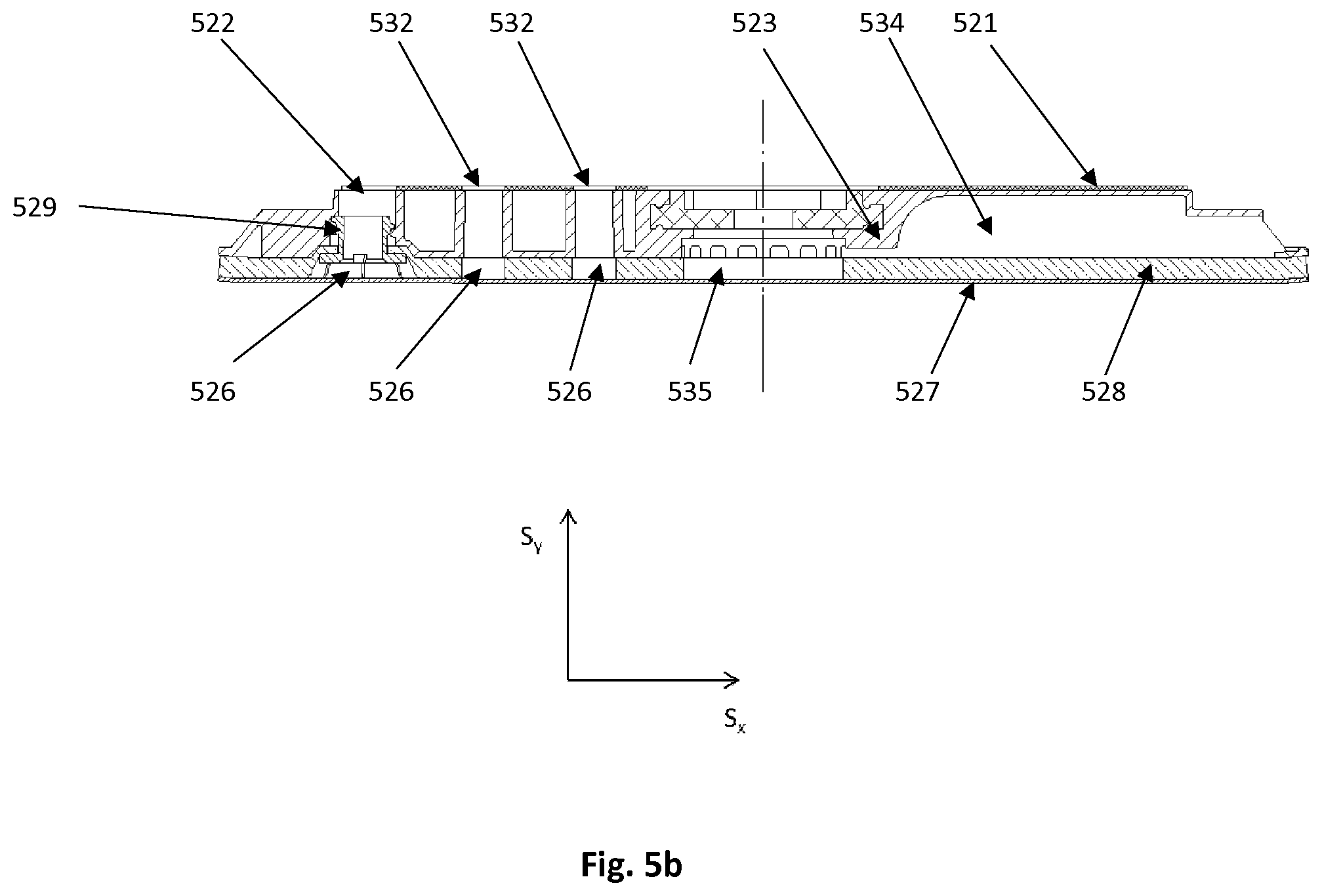
[0019] S.sub.x and S.sub.y denote orthogonal directions [0020] 11 Motor [0021] 12 Motor shaft [0022] 13 Bearing [0023] 14 Spindle [0024] 15 Pad screw [0025] 16 Suction opening [0026] 17 Abrading article [0027] 18 Backing pad [0028] 211 Cover plate [0029] 212 Upper opening [0030] 213 Glass fiber plate [0031] 214 Hard foam [0032] 215 Backing pad hooks [0033] 216 Suction opening [0034] 217 Abrading paper with loops [0035] 221 Cover plate [0036] 222 Upper opening [0037] 223 Glass fiber plate [0038] 224 Hard foam [0039] 225 Backing pad hooks [0040] 226 Suction opening [0041] 227 Abrading net with loops [0042] 231 Cover plate [0043] 232 Upper opening [0044] 233 Glass fiber plate [0045] 234 Hard foam [0046] 235 Backing pad hooks [0047] 236 Suction opening [0048] 237 Abrading net with loops [0049] 238 Pad saver with loops and hooks [0050] 241 Cover plate [0051] 242 Upper opening [0052] 243 Glass fiber plate [0053] 244 Hard foam [0054] 245 Backing pad hooks [0055] 246 Suction opening [0056] 247 Abrading net with loops [0057] 248 Interface with loops, soft foam and hooks [0058] 319 Fixing member [0059] 411 Cover plate [0060] 412 Upper opening [0061] 413 Backing pad [0062] 416 Suction opening [0063] 417 Abrading net [0064] 418 Additional layer [0065] 419 Fixing member [0066] 422 Additional opening [0067] 513 Backing pad [0068] 516 Suction opening [0069] 518 Additional layer [0070] 519 Fixing member [0071] 521 Cover plate [0072] 522 Upper opening [0073] 523 Backing pad [0074] 526 Suction opening [0075] 527 Abrading net [0076] 528 Additional layer [0077] 529 Fixing member [0078] 532 Additional opening [0079] 534 Air inlet conduit [0080] 535 Air inlet opening
[0081] An abrading apparatus to which a backing pad is attached is illustrated in FIG. 1. The abrading apparatus comprises a pneumatic or electrical driven motor 11 for rotating a motor shaft 12. The abrading apparatus comprises a bearing 13 mounted eccentrically with respect to the motor shaft 12 at a lower end of the motor shaft 12. To the bearing 13 a spindle 14 is mounted. Alternatively, the bearing may be mounted in an additional shaft balancer and the motor 11 is arranged to rotate the shaft balancer by means of connection members or gears.
[0082] The backing pad 18 is attached to the spindle 14. The backing pad 18 may be attached to the spindle 14 with a pad screw 15. By this arrangement the backing pad 18 may move in random circles. This refers to oscillating movement. An upper surface of the backing pad 18 refers to a surface that is arranged to be attached to the abrading apparatus. A lower surface of the backing pad 18 refers to the opposite surface on the S.sub.x, S.sub.y plane.
[0083] As illustrated in FIGS. 2a-d, the upper surface of the backing pad 18 comprises a cover plate 211, 221, 231, 241. The cover plate 211, 221, 231, 241 may comprise upper openings 212, 222, 232, 242. The backing pad 18 may comprise a glass fiber plate 213, 223, 233, 243 arranged below the cover plate 211, 221, 231, 241. The backing pad may further comprise a layer comprising hard foam 214, 221, 234, 244 below the glass fiber plate. The lower surface of the backing pad 18 may comprise suction openings 216, 226, 236, 246. The suctions openings 216, 226, 236, 246 may be in connection with the upper openings 212, 222, 232, 242. As illustrated in FIGS. 2a-d, upper opening 212, 222, 232, 242 may be connected to more than one suction openings 216, 226, 236, 246. Thus, one upper opening 212, 222, 232, 242 may serve as an outlet for debris and/or airflow from more than one suction openings 216, 226, 236, 246.
[0084] During abrading a work piece with the abrading system, an abrading article 217, 227, 237, 247 may be attached to the lower surface of the backing pad 18. The abrading article 217, 227, 237, 247 may be attached to the lower surface of the backing pad 18 via attachment elements 215, 225, 235, 245 at the lower surface of the backing pad 18 and at the upper surface of the abrading article 217, 227, 237, 247. The upper surface of the abrading article 217, 227, 237, 247 is detachably attachable to the lower surface of the backing pad 18. The abrading article 217, 227, 237, 247 may comprise abrasive particles. The abrading article 217, 227, 237, 247 may comprise abrasive material, like a sandpaper or a sanding net. An abrading surface refers to the surface that is adapted to be in contact with the surface to be abraded during abrading.
[0085] In all abrading, whether abrading a discrete work piece or larger surface such as a wall or a ceiling, abrading debris is created. This debris may comprise abraded material from the abraded surface as well as abrasive particles detached from the abrading article. Debris may be fine-grained. Debris remaining in the abrading process may adversely affect abrasion efficiency and resulting surface quality, and may clog the abrading article. Accumulated debris on the abrading article and/or the backing pad adds to the weight of the system component on which debris accumulates, resulting in an imbalanced abrading system which may compromise user control, abrading efficiency and surface quality.
[0086] The abrading article 217, 227, 237, 247 may comprise openings corresponding to the suction openings 216, 226, 236, 246 of the backing pad 18 or the abrading article 217, 227, 237, 247 may comprise an abrading net which comprises an open mesh. During abrading the open mesh allows debris and air to flow through the net. When attached to the backing pad 18 the openings of the abrading article 217, 227, 237, 247 are aligned with the suction openings 216, 226, 236, 246 of the backing pad 18.
[0087] The abrading article 217, 227, 237, 247 and the backing pad 18 may be of any shape on the S.sub.x, S.sub.y plane, such as rectangular, triangular, or preferably round. Preferably, the backing pad 18 and the abrading article 217, 227, 237, 247 are substantially of the same shape and size. The backing pad 18 and the abrading article 217, 227, 237, 247 are attachable such that edge portions of the facing surfaces of backing pad 18 and abrading article 217, 227, 237, 247, when attached next to each other, are compatible forming uniform external edge portion. The backing pad 18 and the abrading article 217, 227, 237, 247 have similar external edges in shape, size and form.
[0088] The abrading system may comprise a debris extractor for providing a suction pressure and transporting debris formed during abrading work. The abrading system may comprise a housing for guiding the suction pressure from the debris extractor system to the upper side of the backing pad 18. The suction pressure may be guided through the abrading apparatus above the backing pad 18. From outside the backing pad 18 and possibly through inlet conduits 534 and air inlet opening 535 in the backing pad 18 air may be transported by the suction pressure through suction openings in the backing pad 18 to the debris extractor. With this airflow, debris is transported away from underside of the backing pad 18 and the abrading article 217, 227, 237, 247.
[0089] Although most of the debris is transported away with the air flow caused by the suction pressure, even a small amount of remaining debris may wear the attachment elements 215, 225, 235, 245 of the lower surface of the backing pad 18 and/or the upper surface layer of the abrading article 217, 227, 237, 247. With worn attachment elements 215, 225, 235, 245 the lower surface of the backing pad 18 and/or the upper surface layer of the abrading article 217, 227, 237, 247 lose its/their property to keep the abrading article 217, 227, 237, 247 attached to the backing pad 18.
[0090] For smaller backing pads 18 an additional layer 238, 248 comprising attachment elements may be used in between the backing pad 18 and the abrading article 217, 227, 237, 247. Use of the additional layer 238, 248 may provide savings in costs and a longer lifetime for the backing pad 18. When the attachment elements of the additional layer 238, 248 are worn out, the additional layer 238, 248 instead of the backing pad 18 is to be replaced.
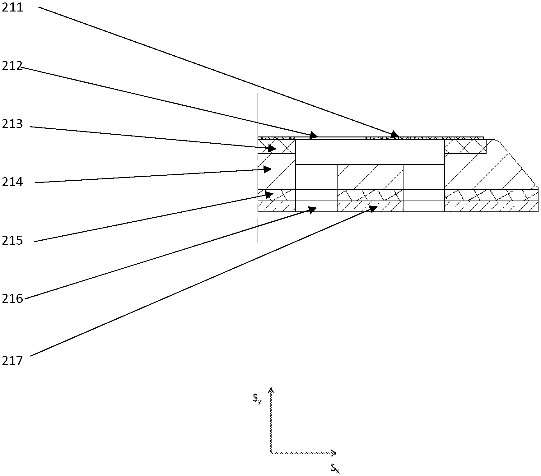
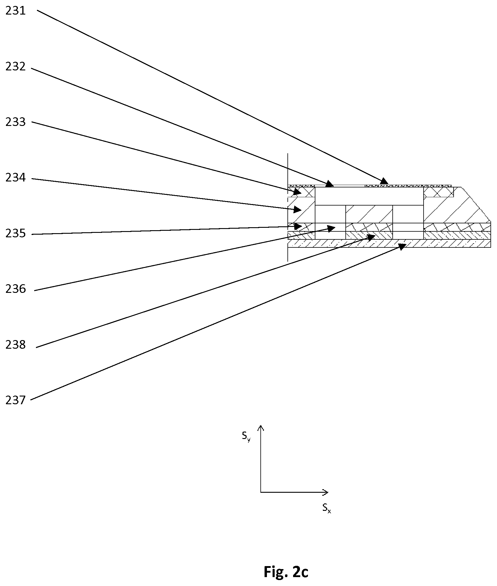
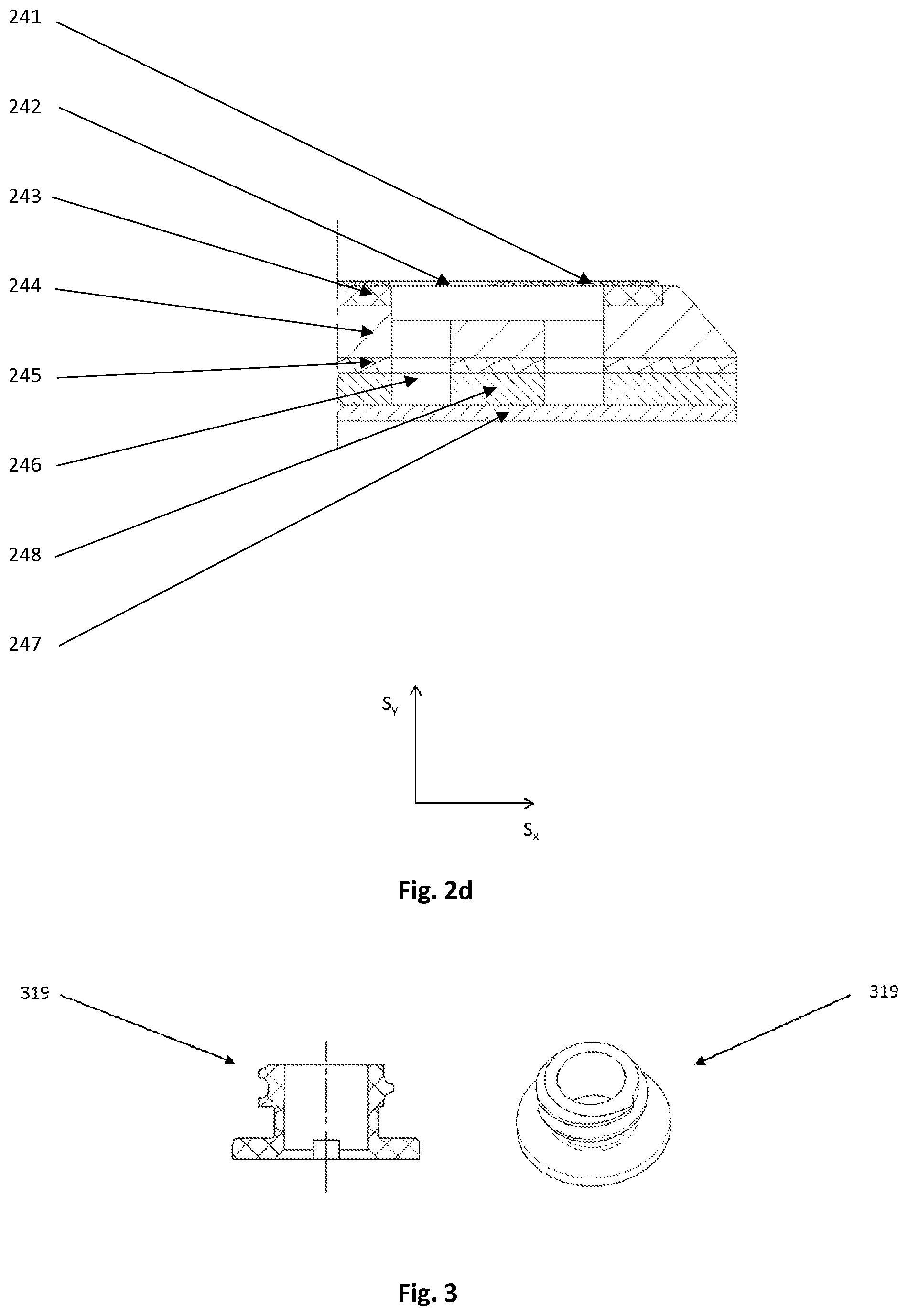
[0091] The additional layer 238, 248 comprises an upper surface, which refers to the surface on the S.sub.x, S.sub.y plane that is arranged to be attached against the backing pad, as well as a lower surface, which refers to the opposite surface of the additional layer 238, 248 on the S.sub.x, S.sub.y plane. The additional layer 238, 248 may be a pad saver or an interface. The pad saver comprises an upper surface and a lower surface. The upper surface and the lower surface of the pad saver may comprise attachment elements. The interface comprises an upper surface, a lower surface and an intermediate layer. The upper surface and the lower surface of the interface may comprise attachment elements.
[0092] However, when using larger backing pads, the additional layer 238, 248 as described above may not extend the lifetime of the backing pad. For larger backing pads, the airflow is not sufficient to keep the area clean when using a weak debris extractor. The debris gathers in the attachment elements between the backing pad and the additional layer 238, 248 and may even shorten the lifetime of the attachment elements of the backing pad.
[0093] A larger backing pad refers to a backing pad comprising a diameter of more than 150 mm. For a backing pad having a shape on the S.sub.x, S.sub.y plane other than round, such as rectangular, triangular, elliptical or otherwise polygonal, the diameter refers to longest possible distance between the edges of the backing pad.
[0094] For larger backing pads, a solution according to an embodiment is provided. According to an embodiment, the backing pad 413, 523 comprises an additional layer 418, 518, 528, which is attached to the backing pad 413, 523 with at least one fixing member 319, 419, 519, 529 as illustrated in FIGS. 3, 4, 5a and 5b.
[0095] The fixing member 319, 419, 519, 529 may be of a type of a screw. The fixing member 319, 419, 519, 529 may comprise screw threads. The fixing member 319, 419, 519, 529 may comprise a stub portion. Alternatively, the fixing member may be e.g. of a snap hook- or expanding type. The fixing member 319, 419, 519, 529 may comprise plastic and/or metal. Advantageously, the fixing member 319, 419, 519, 529 comprises plastic. The fixing member 319, 419, 519, 529 may be hollow in its longitudinal direction. Longitudinal direction refers to the direction of the fixing member 319, 419, 519, 529 arranged to pass through the backing pad 413, 523 and the additional layer 418, 518, 528, being perpendicular to the surfaces of backing pad 413, 523 and additional layer 418, 518, 528. The fixing member 319, 419, 519, 529 passing through the backing pad 413, 523 and the additional layer 418, 518, 528 is arranged to enable the attachment of the backing pad 413, 523 and the additional layer 418, 518, 528. The hollow fixing member 319, 419, 519, 529 allows the air to flow through.
[0096] The additional layer 418, 518, 528 comprises an upper surface, which refers to the surface on the S.sub.x, S.sub.y plane that is arranged to be attached against the backing pad 413, 523, as well as a lower surface, which refers to the opposite surface of the additional layer 418, 518, 528 on the S.sub.x, S.sub.y plane. The additional layer 418, 518, 528 may be a pad saver or an interface. The pad saver comprises an upper surface and a lower surface. The interface comprises an upper surface, a lower surface and an intermediate layer.
[0097] The upper surface of the additional layer 418, 518, 528 may comprise fabric, film, plastic sheet and/or attachment elements, such as loops.
[0098] The lower surface of the additional layer 418, 518, 528 may comprise attachment elements for attaching the additional layer 418, 518, 528 to an abrading article 417, 527. Such attachment elements may enable mechanical or adhesive attachment. Advantageously, such attachment enables removal and re-attachment. Attachment elements may comprise hook-and-loop type of fastening with the capability for convenient re-attachment. In an embodiment, the lower surface layer of the additional layer 418, 518, 528 comprises hooks. In another embodiment, the lower surface layer of the additional layer 418, 518, 528 comprises loops.
[0099] The lower surface of the additional layer 418, 518, 528 may comprise abrasive particles. The abrasive particles may be attached to the lower surface of the additional layer 418, 518, 528 via an adhesive.
[0100] The intermediate layer of the additional layer 418, 518, 528 may comprise a cushion. The intermediate layer may comprise soft material, such as foam. The soft intermediate layer of the additional layer 418, 518, 528 enables the additional layer 418, 518, 528 to adapt to contours of a surface when abrading.
[0101] The cover plate 411, 521 of the backing pad 413, 523 comprises openings. The cover plate 411, 521 of the backing pad 413, 523 may comprise upper openings 412, 522 and additional openings 422, 532. The upper openings 412, 522 and additional openings 422, 532 are technically similar. The term upper opening 412, 522 refers to an opening that may be aligned with a suction opening 416, 516, 526 of the additional layer 418, 518, 528 comprising a fixing member 319, 419, 519, 529 fixed to it. The term additional opening 422, 532 refers to an opening that may be aligned with a suction opening 416, 516, 526 of the additional layer 418, 518, 528 that does not comprise a fixing member 319, 419, 519, 529 fixed to it.
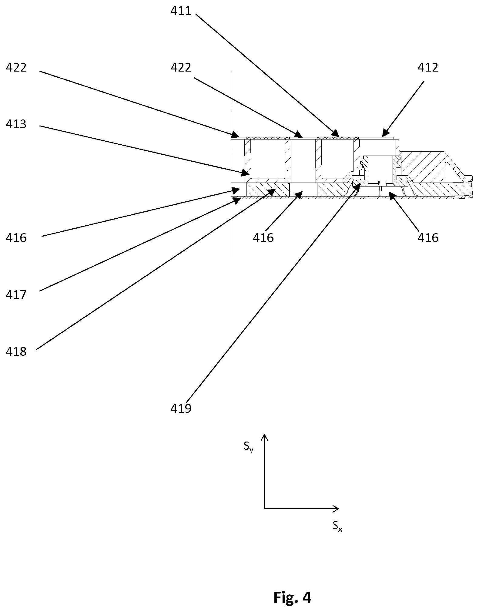
[0102] The additional layer 418, 518, 528 comprises suction openings 416, 516, 526. The suction openings 416, 516, 526 may extend through the additional layer 418, 518, 528. The suction openings 416, 516, 526 extending through the additional layer 418, 518, 528 may be arranged such that when attached to the backing pad 413, 523, the suction openings 416, 516, 526 are aligned with upper openings 412, 522 and additional openings 422, 532 comprised by the cover plate 411, 521. The suction openings 416, 516, 526 may be connected with the upper openings 412, 522 and/or additional openings 422, 532 of the cover plate 411, 521. Through the extended, continuous suction conduit(s) thus formed, debris forming during abrading work may be transported together with the airflow caused by the suction pressure provided by the debris extractor. Upper opening 412, 522 may be connected to more than one suction openings 416, 516, 526. Thus, one upper opening 412, 522 or one additional opening 422, 532 may serve as an outlet for debris and/or airflow from more than one suction openings 416, 516, 526. The debris extractor system is arranged to guide debris away from the additional layer 418, 518, 528 and the abrading surface of the abrading article 417, 527.
[0103] According to an embodiment, the additional layer 418, 518, 528 is attached to the backing pad 413, 523 with at least one fixing member 319, 419, 519, 529. The at least one fixing member 319, 419, 519, 529 is hollow in its longitudinal direction. A fixing member 319, 419, 519, 529, which is arranged through openings of a backing pad and an additional layer or an abrading article, may form a border at circumference of the openings. Thus opening may be of smaller area and/or volume due to the fixing member 319, 419, 519, 529, but it still allows air and/or debris to flow through.
[0104] According to an embodiment, the additional layer 418, 518, 528 is attached to the backing pad 413, 523 with multiple fixing members 319, 419, 519, 529. The fixing members 419, 519, 529 may be arranged in a symmetrical or unsymmetrical manner. The fixing members 319, 419, 519, 529 may be fixed to the suction openings 416, 516, 526 of the additional layer 418, 518, 528. The fixing members may be fixed in alignment with the upper openings 412, 522 of the cover plate 411, 521. The suction openings 416, 516, 526 of the additional layer 418, 518, 528 are in connection with the upper openings 412, 522 and additional openings 422, 532 of the cover plate 411, 521 of the backing pad 413, 523. The hollow fixing members 319, 419, 519, 529 allow the debris to be transported with air through the fixing members. The debris may also be transported through the suction conduits formed by the suction openings 416, 516, 526 of the additional layer 418, 518, 528 and the additional openings 422, 532 of the cover plate 411, 521 of the backing pad 413, 523.
[0105] An air inlet conduit 534 of the backing pad 523 is arranged to lead air via an air inlet opening 535 to the abrading surface of the abrading article 527. This increases the air flow from the abrading surface of the abrading article 527 to the suction openings 526.
[0106] According to another embodiment, the additional layer may be attached to the backing pad with one fixing member, which fixing member is arranged in the center of the backing pad. The center of the backing pad refers to a center point of the backing pad in the S.sub.x, S.sub.y plane. The fixing member is hollow in its longitudinal direction. The hollow fixing member allows the air to flow through. The hollow fixing member allows the debris to be transported through the fixing member. The debris may also be transported through the suction conduits formed by the suction openings of the additional layer and the additional openings of the cover plate of the backing pad.
[0107] According to an aspect of the application, a backing pad arrangement for an abrading system, the backing pad arrangement comprising a backing pad, wherein the lower surface of the backing pad comprises at least one opening, which at least one opening is adapted to receive a fixing member, is provided. The backing pad arrangement further comprises an additional layer adapted to be attached to the backing pad. The additional layer comprises an upper surface, a lower surface and at least one opening which extends through the additional layer. The additional layer is attached to the backing pad with at least one fixing member. Alternatively, the backing pad arrangement further comprises an abrading article adapted to be attached to the backing pad. The abrading article comprises at least one opening, which extends through the abrading article. The abrading article is attached to the backing pad with at least one fixing member. The at least one fixing member is hollow in its longitudinal direction. The additional layer or the abrading article may be attached to the backing pad with two or more fixing members. The additional layer or the abrading article may be attached to the backing pad with one fixing member arranged in the center of the backing pad. The fixing member may be of screw-, snap hook- or expanding type. The backing pad may comprise at least one air inlet conduit for conducting air to an abrading surface. The additional layer may comprise a soft intermediate layer between the upper surface and the lower surface of the additional layer. The lower surface of the additional layer may comprise abrasive particles. The backing pad may comprise at least one additional opening not adapted to receive a fixing member.
[0108] According to another aspect of the application, a backing pad arrangement for an abrading system, the backing pad arrangement comprising a backing pad, wherein the lower surface of the backing pad comprises two or more openings, said openings being adapted to receive fixing members, is provided. The backing pad arrangement further comprises an additional layer adapted to be attached to the backing pad, which additional layer comprises an upper surface, a lower surface and two or more openings which extend through the additional layer. The additional layer is attached to the backing pad with two or more fixing members. Alternatively, the backing pad arrangement further comprises an abrading article adapted to be attached to the backing pad, which abrading article comprises two or more openings, which extend through the abrading article. The abrading article is attached to the backing pad with two or more fixing members. The fixing members may be of screw-, snap hook- or expanding type. The fixing members may be non-hollow. The backing pad may comprise at least one air inlet conduit for conducting air to an abrading surface. The additional layer may comprise a soft intermediate layer between the upper surface and the lower surface of the additional layer. The lower surface of the additional layer may comprise abrasive particles. The backing pad may comprise at least one additional opening not adapted to receive a fixing member.
[0109] According to yet another aspect of the application, an abrading system comprising an abrading apparatus, wherein the abrading system further comprises a backing pad arrangement according to the application, is provided. The abrading system may comprise a debris extractor system adapted to provide suction pressure and to remove debris formed during abrading work. The debris extractor system may be arranged to guide debris away from the additional layer and the abrading surface. The debris extractor system may be adapted to guide debris via at least one of the following: the additional layer, the abrading article, the backing pad, the fixing member(s), opening(s) of the additional layer, opening(s) of the abrading article, opening(s) of a cover plate of the backing pad. Opening(s) of the additional layer or opening(s) of the abrading article, and opening(s) of the cover plate of the backing pad may be connected in order to form conduit(s) for removing debris.
[0110] The lifetime of a backing pad arrangement according to an embodiment was tested and compared with a backing pad arrangement having the additional layer attached to it via hook-and-loop type attachment elements. Depending on the material of the attachment elements, the average lifetime of the latter backing pad arrangement was shown to be between 12 and 17 hours. For the backing pad arrangement according to the embodiment, the lifetime of the additional layer was shown to be between 35 and 42 hours. Moreover, after that the backing pad was not shown to be worn out and could be used again by replacing the additional layer with a new one.
[0111] The above presented provides a cost efficient and ecological backing pad for an abrading system. It is far more cost efficient to replace the additional layer instead of the whole backing pad. The extended lifetime of backing pads decreases wasted backing pads and thus saves environment.
[0112] Many variations of the present application will suggest themselves to those skilled in the art in light of the description in previous. Such obvious variations are within the full intended scope of the appended claims.
* * * * *
D00000
D00001
D00002
D00003
D00004
D00005
D00006
D00007
XML
uspto.report is an independent third-party trademark research tool that is not affiliated, endorsed, or sponsored by the United States Patent and Trademark Office (USPTO) or any other governmental organization. The information provided by uspto.report is based on publicly available data at the time of writing and is intended for informational purposes only.
While we strive to provide accurate and up-to-date information, we do not guarantee the accuracy, completeness, reliability, or suitability of the information displayed on this site. The use of this site is at your own risk. Any reliance you place on such information is therefore strictly at your own risk.
All official trademark data, including owner information, should be verified by visiting the official USPTO website at www.uspto.gov. This site is not intended to replace professional legal advice and should not be used as a substitute for consulting with a legal professional who is knowledgeable about trademark law.