System, Method And Apparatus For Rehabilitation And Exercise
Bissonnette; Michael ; et al.
U.S. patent application number 16/869954 was filed with the patent office on 2020-11-12 for system, method and apparatus for rehabilitation and exercise. This patent application is currently assigned to OrthoGenesys, Inc.. The applicant listed for this patent is OrthoGenesys, Inc.. Invention is credited to Michael Bissonnette, Philip Powers, James D. Steidl.
| Application Number | 20200353310 16/869954 |
| Document ID | / |
| Family ID | 1000004855513 |
| Filed Date | 2020-11-12 |


View All Diagrams
| United States Patent Application | 20200353310 |
| Kind Code | A1 |
| Bissonnette; Michael ; et al. | November 12, 2020 |
SYSTEM, METHOD AND APPARATUS FOR REHABILITATION AND EXERCISE
Abstract
A rehabilitation and exercise system can include a base. A static device can be coupled to the base and configured to provide isometric exercise for a user by receiving static force from the user to facilitate at least one of osteogenesis or muscle hypertrophy for the user. In addition, a dynamic device can be coupled to the base and configured to provide a dynamic exercise for the user by being moved by the user to facilitate at least one of osteogenesis and muscle hypertrophy for the user.
| Inventors: | Bissonnette; Michael; (Denver, CO) ; Powers; Philip; (Denver, CO) ; Steidl; James D.; (Denver, CO) | ||||||||||
| Applicant: |
|
||||||||||
|---|---|---|---|---|---|---|---|---|---|---|---|
| Assignee: | OrthoGenesys, Inc. Longmont CO |
||||||||||
| Family ID: | 1000004855513 | ||||||||||
| Appl. No.: | 16/869954 | ||||||||||
| Filed: | May 8, 2020 |
Related U.S. Patent Documents
| Application Number | Filing Date | Patent Number | ||
|---|---|---|---|---|
| 62846434 | May 10, 2019 | |||
| 62858244 | Jun 6, 2019 | |||
| Current U.S. Class: | 1/1 |
| Current CPC Class: | A63B 21/015 20130101; A63B 2022/0641 20130101; A63B 21/4035 20151001; A63B 2230/75 20130101; A63B 22/0605 20130101 |
| International Class: | A63B 22/06 20060101 A63B022/06; A63B 21/00 20060101 A63B021/00; A63B 21/015 20060101 A63B021/015 |
Claims
1. A rehabilitation and exercise system, comprising: a base; a static device configured to be coupled to the base and configured to provide isometric exercise for a user by receiving static force from the user to facilitate at least one of osteogenesis or muscle hypertrophy for the user; and a dynamic device configured to be coupled to the base and configured to provide a dynamic exercise for the user by being moved by the user to facilitate at least one of osteogenesis and muscle hypertrophy for the user.
2. The system of claim 1, further comprising upper seat handles configured to be coupled to and extend laterally from the base, the upper seat handles are configured to be rotated by the user.
3. The system of claim 2, wherein a position of an assembly of the upper seat handles is configured to be adjusted and repositionable relative to the base.
4. The system of claim 1, wherein the base comprises a longitudinal base length and a lateral base width; and the system further comprises: a main post configured to be coupled to the base at a first base end, and the main post is configured to extend vertically from the base.
5. The system of claim 4, wherein the dynamic device is configured to be attached to the base adjacent the main post, and the dynamic device comprises a cycling mechanism having pedals configured to be selectively engaged by the user.
6. The system of claim 5, wherein the pedals are offset from and rotatable about a cycle axis of the cycling mechanism, and the cycle axis extends laterally relative to the base.
7. The system of claim 5, wherein the cycling mechanism comprises: discs rotatably coupled to a cycle axis, each disc having a respective pedal axle coupled to a respective disc and offset from the cycle axis; the pedals are rotatably coupled to respective ones of the pedal axles.
8. The system of claim 7, wherein each pedal comprises a semicircular panel that extends from a respective disc, and the semicircular panels are configured to be selectively engaged by the user.
9. The system of claim 4, wherein the main post has a distal post end coupled to a lateral bar that extends laterally from the main post, the lateral bar has bar ends each having a bar handle, the bar handles extend transversely from the bar ends and are configured to be selectively engaged by the user.
10. The system of claim 4, wherein the main post has a distal post end with pivoting assemblies that are pivotable about the distal post end, each pivoting assembly comprises a pivoting arm and a pivoting handle, each pivoting arm has a distal arm end, and the pivoting handles are pivotally attached to the distal arm ends, respectively, and configured to be engaged by the user.
11. The system of claim 1, further comprising a control console configured to provide information to and instruct the user regarding use of the system prior to or during use of the system.
12. The system of claim 11, further comprising load cells configured to sense at loads during use of the system, the load cells are electrically coupled to the control console and mechanically coupled to the static and dynamic devices.
13. The system of claim 12, wherein the load cells comprise at least one of strain gauges, bending-type load cells, double-beam-type load cells, half-bridge-type load cells, S-type load cells, button-type load cells, piezoelectric load cells or hydraulic load cells.
14. The system of claim 1, wherein the base extends longitudinally and comprises a base length from a first base end to a second base end; the base extends laterally and comprises a base width from a first base side to a second base side; the base defines at least one base foot area disposed centrally to the base on which the user can stand during at least one of the isometric exercise and the dynamic exercise.
15. The system of claim 14, wherein the at least one base foot area comprises a pair of base foot areas, each of which extends longitudinally a distance along one of the first base side and the second base side; and the pair of base foot areas each extends laterally toward an opposite one of the first base side and the second base side.
16. The system of claim 1, wherein the dynamic device comprises at least one flexible band configured to be selectively engaged by and provide resistance to the user.
17. A rehabilitation and exercise system, comprising: a base; a static device configured to be coupled to the base and configured to provide isometric exercise for a user by receiving static force from the user to facilitate at least one of osteogenesis or muscle hypertrophy for the user; a dynamic device configured to be coupled to the base and configured to provide a dynamic exercise for the user by being moved by the user to facilitate at least one of osteogenesis and muscle hypertrophy for the user; the base comprises a longitudinal base length and a lateral base width, a main post is configured to be coupled to the base at a first base end, the main post is configured to extend vertically from the base, the dynamic device is configured to be attached to the base adjacent the main post, and the dynamic device comprises a cycling mechanism having pedals configured to be selectively engaged by the user; and a control console configured to provide information to and instruct the user regarding use of the system prior to or during use of the system.
18. The system of claim 17, further comprising load cells configured to sense at loads during use of the system, the load cells are electrically coupled to the control console and mechanically coupled to the static and dynamic devices; the load cells comprise at least one of strain gauges, bending-type load cells, double-beam-type load cells, half-bridge-type load cells, S-type load cells, button-type load cells, piezoelectric load cells or hydraulic load cells.
19. The system of claim 17, wherein the base extends longitudinally and comprises a base length from a first base end to a second base end; the base extends laterally and comprises a base width from a first base side to a second base side; the base defines at least one base foot area disposed centrally to the base on which the user can stand during at least one of the isometric exercise and the dynamic exercise; and the at least one base foot area comprises a pair of base foot areas, each of which extends longitudinally a distance along one of the first base side and the second base side; and the pair of base foot areas each extends laterally toward an opposite one of the first base side and the second base side.
20. A method of using an exercise machine for exercising a user, the method comprising: providing an exercise machine having a static device and a dynamic device; selectively and sequentially engaging the static and dynamic devices by the user; and receiving by the static and dynamic devices applications of force by the user sufficient to facilitate osteogenesis and muscle hypertrophy for the user.
Description
[0001] This application claims priority to and the benefit of U.S. Prov. Pat. App. No. 62/846,434, filed May 10, 2019 (Atty. Dkt. 87292-700), and U.S. Prov. Pat. App. No. 62/858,244, filed Jun. 6, 2019 (Atty. Dkt. 87292-500), each of which is incorporated herein by reference in its entirety.
BACKGROUND
Technical Field
[0002] This disclosure generally relates to exercise and, in particular, to a system, method and apparatus for a rehabilitation and exercise device.
Description of the Related Art
[0003] Devices rehabilitating and exercising a user can be used to facilitate osteogenesis and muscle hypertrophy. Such machines typically provide for one type of static or dynamic activity for a user to facilitate osteogenesis and muscle hypertrophy. For users with limited mobility, moving between different machines that facilitate only one type of activity can present challenges that limit the ability of the user to rehabilitate and exercise.
[0004] With osteogenic activity a user may perform an exercise (e.g., bench press, pull down, arm curl, etc.) using equipment to improve osteogenesis, bone growth, bone density, muscular hypertrophy, or some combination thereof. Such equipment may include non-movable portions to which the user exerts a load. For example, to perform some exercises, the user may position themselves on or adjacent the machine, and apply force to the machine while the body of the user remains in the same position. Although conventional solutions are workable, improvements continue to be of interest.
SUMMARY
[0005] Embodiments of a rehabilitation and exercise system can include a base. A static device can be coupled to the base and configured to provide isometric exercise for a user by receiving static force from the user to facilitate at least one of osteogenesis or muscle hypertrophy for the user. In addition, a dynamic device can be coupled to the base and configured to provide a dynamic exercise for the user by being moved by the user to facilitate at least one of osteogenesis and muscle hypertrophy for the user.
[0006] Other areas of applicability will become apparent from the description provided herein. The description and specific examples in this summary are intended for purposes of illustration only and are not intended to limit the scope of the present disclosure.
BRIEF DESCRIPTION OF THE DRAWINGS
[0007] The drawings described herein are for illustrative purposes only of selected embodiments and not all possible implementations. The drawings are not intended to limit the scope of the present disclosure. For a detailed description of example embodiments, reference will now be made to the accompanying drawings, in which:
[0008] FIGS. 1-4 illustrate a first exemplary embodiment of an exercise machine, according to aspects of the disclosure;
[0009] FIG. 5 shows examples of a plurality of load cells that can be used in the exercise machine, according to aspects of the disclosure;
[0010] FIGS. 6-7 illustrate a second exemplary embodiment of an exercise machine, according to aspects of the disclosure
[0011] FIGS. 8-13 illustrate a third exemplary embodiment of an exercise machine, according to aspects of the disclosure;
[0012] FIGS. 14-20 illustrate a fourth exemplary embodiment of an exercise machine, according to aspects of the disclosure;
[0013] FIGS. 21-26 illustrate a fifth exemplary embodiment of an exercise machine, according to aspects of the disclosure; and
[0014] FIGS. 27-28 illustrate a sixth exemplary embodiment of an exercise machine, according to aspects of the disclosure.
[0015] FIG. 29 is a perspective view of one embodiment of a system for isometric exercise and rehabilitation.
[0016] FIG. 30 is a reverse perspective view of the system of FIG. 29.
[0017] FIG. 31 is a side view of the system of FIG. 29.
[0018] FIG. 32 is a side view of the system of FIG. 29 with a user performing a leg-press-style exercise.
[0019] FIG. 33 is a side view of the system of FIG. 29 with a user performing a chest-press-style exercise.
[0020] FIG. 34 is a side view of the system of FIG. 29 with a user performing a core-pull-style exercise.
[0021] FIG. 35 is a side view of the system of FIG. 29 with a user performing a suitcase lift-style exercise.
[0022] FIG. 36 is an enlarged view of an embodiment of a handle portion of the system of FIG. 29 with a user performing a suitcase lift-style exercise.
[0023] FIG. 37 is an exploded perspective view of an embodiment of a handle for the system of FIG. 29.
[0024] FIG. 38 is an exploded side view of the handle of FIG. 37.
[0025] FIG. 39 is a sectional side view of an embodiment of the handle of FIG. 37.
[0026] FIG. 40 illustrates four examples of load cells that can be used in the system.
[0027] FIG. 41 is a side view of an alternative embodiment of a system for isometric exercise and rehabilitation with a user performing a leg-press-style exercise.
[0028] FIG. 42 illustrates skeletal stress regions of a user during the leg-press-style exercise of FIG. 41.
[0029] FIG. 43 is a side view of system of FIG. 41 with the user performing a chest-press-style exercise.
[0030] FIG. 44 depicts skeletal stress regions of the user during the chest-press-style exercise of FIG. 43.
[0031] FIG. 45 is a side view of the system of FIG. 41 with the user performing a suitcase-lift-style exercise.
[0032] FIG. 46 illustrates skeletal stress regions during the suitcase-lift-style exercise of FIG. 45.
[0033] FIG. 47 is a side view of the system of FIG. 41 with the user performing an arm-curl-style exercise.
[0034] FIG. 48 depicts skeletal stress regions during the arm-curl-style exercise of FIG. 47.
[0035] FIG. 49 is a side view of the system of FIG. 41 with the user performing a core-pull-style exercise.
[0036] FIG. 50 illustrates a skeletal stress region during the core-pull-style exercise of FIG. 49.
[0037] FIG. 51 is a side view of the system of FIG. 41 with the user performing a grip-strength exercise.
NOTATION AND NOMENCLATURE
[0038] Various terms are used to refer to particular system components. Different entities may refer to a component by different names--this document does not intend to distinguish between components that differ in name but not function. In the following discussion and in the claims, the terms "including" and "comprising" are used in an open-ended fashion, and thus should be interpreted to mean "including, but not limited to . . . ." Also, the term "couple" or "couples" is intended to mean either an indirect or direct connection. Thus, if a first device couples to a second device, that connection may be through a direct connection or through an indirect connection via other devices and connections.
DETAILED DESCRIPTION
[0039] The subject matter of each of U.S. Pat. No. 10,226,663, issued Mar. 12, 2019; U.S. Pat. No. 10,173,094, issued Jan. 8, 2019; U.S. Pat. No. 10,173,095, issued Jan. 8, 2019; U.S. Pat. No. 10,173,096, issued Jan. 8, 2019; and U.S. Pat. No. 10,173,097, issued Jan. 8, 2019; and U.S. pending patent application Ser. No. 16/241,167 filed Jan. 7, 2019; Ser. No. 16/812,462 filed Mar. 9, 2020; Ser. No. 16/813,158 filed Mar. 9, 2020; Ser. No. 16/813,158 filed Mar. 9, 2020; and Ser. No. 16/813,303 filed Mar. 9, 2020, is incorporated herein by reference.
[0040] Osteogenesis
[0041] As typically healthy people grow from infants to children to adults, they experience bone growth. Such, growth, however, typically stops at approximately age 30. After that point, without interventions as described herein, bone loss (called osteoporosis), can start to occur. This does not mean that the body stops creating new bone. Rather, it means that the rate at which it creates new bone tends to slow, while the rate at which bone loss occurs tends to increase.
[0042] In addition, as people age and/or become less active than they once were, they may experience muscle loss. For example, muscles that are not used often may reduce in muscle mass. As a result, the muscles become weaker. In some instances, people may be affected by a disease, such as muscular dystrophy, that causes the muscles to become progressively weaker and to have reduced muscle mass. To increase the muscle mass and/or reduce the rate of muscle loss, people may exercise a muscle to cause muscular hypertrophy, thereby strengthening the muscle as the muscle grows. Muscular hypertrophy may refer to an increase in a size of skeletal muscle through a growth in size of its component cells. There are two factors that contribute to muscular hypertrophy, (i) sarcoplasmic hypertrophy (increase in muscle glycogen storage), and (ii) myofibrillar hypertrophy (increase in myofibril size). The growth in the cells may be caused by an adaptive response that serves to increase an ability to generate force or resist fatigue.
[0043] The rate at which such bone or muscle loss occurs generally accelerates as people age. A net growth in bone can ultimately become a net loss in bone, longitudinally across time. In an average case, but noting that significant individual variations in age do occur, by the time women are over 50 and men are over 70, net bone loss can reach a point where brittleness of the bones is so great that an increased risk of life-altering fractures can occur. Examples of such fractures include fractures of the hip and femur. Of course, fractures can also occur due to participation in athletics or due to accidents. In such cases, it is just as relevant to have a need for bone growth which heals or speeds the healing of the fracture.
[0044] To understand why such fractures occur, it is useful to recognize that bone is itself porous, with a somewhat-honeycomb like structure. This structure may be dense and therefore stronger or it may be variegated, spread out and/or sparse, such latter structure being incapable of continuously or continually supporting the weight (load) stresses experienced in everyday living. When such loads exceed the support capability of the structure at a stressor point or points, a fracture occurs. This is true whether the individual had a fragile bone structure or a strong one: it is a matter of physics, of the literal "breaking point."
[0045] It is therefore preferable to have a means of mitigating or ameliorating bone loss and of healing fractures; and, further, of encouraging new bone growth, thus increasing the density of the structure described hereinabove, thus increasing the load-bearing capacities of same, thus making first or subsequent fractures less likely to occur, and thus improving the individual's quality of life. The process of bone growth itself is referred to as osteogenesis, literally the creation of bone.
[0046] It is also preferable to have a means for mitigating or ameliorating muscle mass loss and weakening of the muscles. Further, it is preferable to encourage muscle growth by increasing the muscle mass through exercise. The increased muscle mass may enable a person to exert more force with the muscle and/or to resist fatigue in the muscle for a longer period of time.
[0047] In order to create new bone, at least three factors are necessary. First, the individual must have a sufficient intake of calcium, but second, in order to absorb that calcium, the individual must have a sufficient intake and absorption of Vitamin D, a matter problematic for those who have cystic fibrosis, who have undergone gastric bypass surgery or have other absorption disorders or conditions which limit absorption. Separately, supplemental estrogen for women and supplemental testosterone for men can further ameliorate bone loss. On the other hand, abuse of alcohol and smoking can harm one's bone structure. Medical conditions such as, without limitation, rheumatoid arthritis, renal disease, overactive parathyroid glands, diabetes or organ transplants can also exacerbate osteoporosis. Ethical pharmaceuticals such as, without limitation, hormone blockers, seizure medications and glucocorticoids are also capable of inducing such exacerbations. But even in the absence of medical conditions as described hereinabove, Vitamin D and calcium taken together may not create osteogenesis to the degree necessary or possible; or ameliorate bone loss to the degree necessary or possible.
[0048] To achieve such a degree of osteogenesis, therefore, one must add in the third factor: exercise. Specifically, one must subject one's bones to a force at least equal to certain multiple of body weight, such multiples varying depending on the individual and the specific bone in question. As used herein, "MOB" means Multiples of Body Weight. It has been determined through research that subjecting a given bone to a certain threshold MOB (this may also be known as a "weight-bearing exercise"), even for an extremely short period of time, one simply sufficient to exceed the threshold MOB, encourages and fosters osteogenesis in that bone.
[0049] Further, a person can achieve muscular hypertrophy by exercising the muscles for which increased muscle mass is desired. Strength training and/or resistance exercise may cause muscle tissue to increase. For example, pushing against or pulling on a stationary object with a certain amount of force may trigger the cells in the associated muscle to change and cause the muscle mass to increase.
[0050] The subject matter disclosed herein relates to a machine and methods and apparatuses appurtenant thereto, not only capable of enabling an individual, preferably an older, less mobile individual or preferably an individual recovering from a fracture, to engage easily in osteogenic exercises, but capable of using predetermined thresholds or dynamically calculating them, such that the person using the machine can be immediately informed through visual and/or other sensorial feedback, that the osteogenic threshold has been exceeded, thus triggering osteogenesis for the subject bone (or bones) and further indicating that the then-present exercise may be terminated, enabling the person to move to a next machine-enabled exercise to enable osteogenesis in a preferably different bone or bones. In some embodiments, the thresholds may pertain to measurements of grip strength that are obtained while the user is performing a grip-strengthening-style exercise.
[0051] For those with any or all of the osteoporosis-exacerbating medical conditions described herein, such a machine can slow the rate of net bone loss by enabling osteogenesis to occur without exertions which would not be possible for someone whose health is fragile, not robust. Another benefit of the disclosed techniques, therefore, is enhancing a rate of healing of fractures in athletically robust individuals.
[0052] Last, while this discussion has focused purely on osteogenesis, an additional benefit is that partaking in exercises which focus on osteogenesis may, in certain embodiments, also increase muscle strength and, as a physiological system, musculoskeletal strength.
[0053] Hypertrophy
[0054] Hypertrophy is defined as an increase in volume or bulk of a tissue or organ produced entirely by enlargement of existing cells. Hypertrophy as described herein specifically refers to muscle hypertrophy. The exercises performed using the disclosed apparatus may involve the following types of muscle contractions: concentric contractions (shorten), eccentric contractions (lengthen), and isometric contractions (remain the same).
[0055] Bone Exercises and their Benefits
[0056] The following exercises achieve bone strengthening results by exposing relevant parts of a user to static or isometric forces which are selected multiples of body weight (MOB) of the user, a threshold level above which bone mineral density increases. The specific MOB-multiple threshold necessary to effect such increases will naturally vary from individual to individual and may be more or less for any given individual. "Bone-strengthening," as used herein, specifically includes, without limitation, a process of osteogenesis, whether due to the creation of new bone as a result of an increase in the bone mineral density; or proximately to the introduction or causation of microfractures in the underlying bone. The exercises referred to are as follows.
[0057] Leg Press
[0058] An isometric leg-press-style exercise to improve muscular strength in the following key muscle groups: gluteals, hamstrings, quadriceps, spinal extensors and grip muscles, as well as to increase resistance to skeletal fractures in leg bones such as the femur. In one example, the leg-press-style exercise can be performed at approximately 4.2 MOB or more of the user.
[0059] Chest Press
[0060] An isometric chest-press-style exercise to improve muscular strength in the following key muscle groups: pectorals, deltoids, and tricep and grip muscles, as well as to increase resistance to skeletal fractures in the humerus, clavicle, radial, ulnar and rib pectoral regions. In one example, the chest-press-style exercise can be performed at approximately 2.5 MOB or more of the user.
[0061] Suitcase Lift
[0062] An isometric suitcase-lift-style exercise to improve muscular strength in the following key muscle groups: gluteals, hamstrings, quadriceps, spinal extensors, abdominals, and upper back and grip muscles, as well as to increase resistance to skeletal fractures in the femur and spine. In one example, the suitcase-lift-style exercise can be performed at approximately 2.5 MOB or more of the user.
[0063] Arm Curl
[0064] An isometric arm-curl-style exercise to improve muscular strength in the following key muscle groups: biceps, brachialis, brachioradialis, grip muscles and trunk, as well as to increase resistance to skeletal fractures in the humerus, ribs and spine. In one example, the arm-curl-style exercise can be performed at approximately 1.5 MOB or more of the user.
[0065] Core Pull
[0066] An isometric core-pull-style exercise to improve muscular strength in the following key muscle groups: elbow flexors, grip muscles, latissimus dorsi, hip flexors and trunk, as well as to increase resistance to skeletal fractures in the ribs and spine. In one example, the core-pull-style exercise can be performed at approximately 1.5 MOB or more of the user.
[0067] Grip Strength
[0068] A grip-strengthening-style exercise which may preferably be situated around, or integrated with, a station in an exercise machine, in order to improve strength in the muscles of the hand, forearm, or other gripping extremity. Moreover, measurement of grip strength can be taken prior to, during, and/or after the grip-strengthening-style exercise is performed. Grip strength is medically salient because it has been positively correlated with a better state of health. Accordingly, measurements of grip strength can be used to in conjunction with and/or to guide, assist, or enhance the exercise and rehabilitation of a user. Furthermore, a measurement of grip strength during the grip-strengthening-style exercise can be used to provide real-time-feedback to the user. Such real-time-feedback during the grip-strengthening-style exercise can be used to challenge the user to increase a grip strength to further strengthen the muscles of the hand, forearm, or other gripping extremity.
[0069] In the following description, details are set forth to facilitate an understanding of the present disclosure. In some instances, certain structures and techniques have not been described or shown in detail in order not to obscure the disclosure.
[0070] The following discussion is directed to various embodiments of the present disclosure. Although these embodiments are given as examples, the embodiments disclosed should not be interpreted, or otherwise used, as limiting the scope of the disclosure, including the claims. In addition, one of ordinary skill in the art will understand that the following description has broad application. The discussion of any embodiment is meant only to be exemplary of that embodiment. Thus, the discussion is not intended to intimate that the scope of the disclosure, including the claims, is limited to that embodiment.
[0071] Exercise machines can provide isometric exercises to facilitate osteogenesis and muscle hypertrophy. Such exercise machines can include equipment in which there are no moving parts while the user is performing an isometric exercise. While there may be some flexing: (i) under load, (ii) incidental movement resulting from the tolerances of interlocking parts, and (iii) parts that can move while a user performs adjustments on the exercise machines, these flexions and movements can comprise, without limitation, exercise machines capable of isometric exercise and rehabilitation. In addition, such exercise machines may also include equipment or devices including moving parts to provide dynamic exercises to facilitate osteogenesis and muscle hypertrophy. A dynamic exercise can be, but is not limited to, an exercise where a user participates in an activity where the user moves and some resistance or load is provided against the movement of the user.
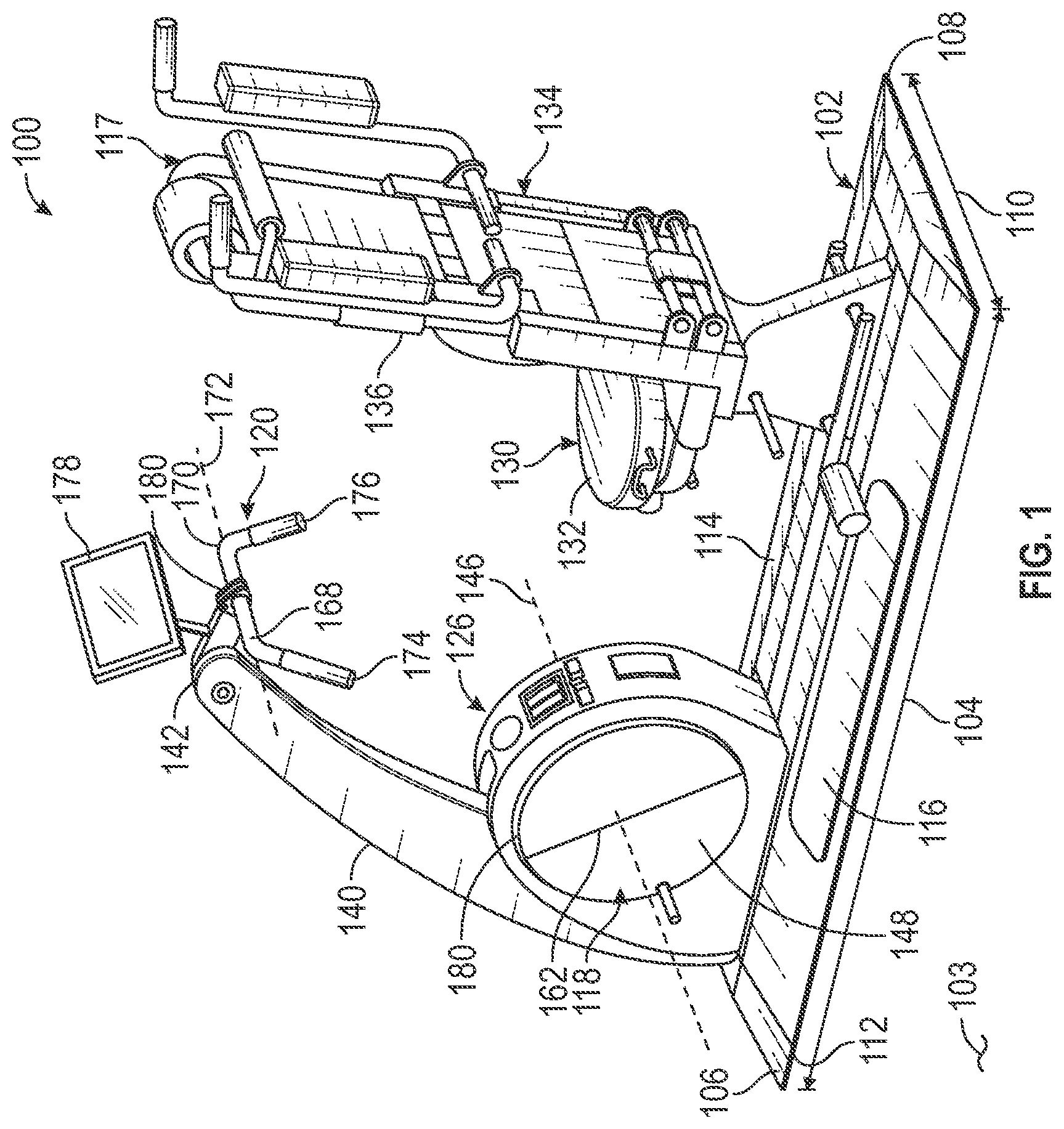
[0072] Referring to the FIGS. 1-28, wherein like numerals indicate corresponding parts throughout the views, an exercise machine is shown. More specifically, and with reference to FIGS. 1-4, a first exemplary embodiment of an exercise machine 100 for exercising at least one body part of a user. The exercise machine 100 can include a base 102 that can support the exercise machine 100, and the base 102 may be configured to rest on a ground surface 103. The base 102 may extend longitudinally and can define a base length 104 from a first base end 106 to a second base end 108. The base 102 may also extend laterally and can define a base width 110 from a first base side 112 to a second base side 114. The base 102 may also define at least one base foot area 116 disposed centrally between the base ends 106, 108 and adjacent one of the first and second base sides 112, 114. The at least one foot area 116 is textured to prevent a user from slipping when standing on the at least one foot area 116. As shown, the at least one base foot area 116 can include a pair of base foot areas 116. Each of the pair of base foot areas 116 may extend longitudinally a foot area distance along each of the first base side 112 and the second base side 114. The pair of base foot areas 116 can also each extend laterally toward an opposite one of the first base side 112 and the second base side 114.
[0073] In addition, the exercise machine 100 may include at least one osteogenic or isometric device (hereinafter referred to as an "isometric device"). Hereafter, the isometric device may refer to any one of the isometric devices 117, 118, 119, 120, 221, 222, 323, 324, 423, 424, 425, 521, 525. The isometric device can be coupled to the base 102. The isometric device can be configured to receive an application of force by the user during an isometric exercise sufficient to facilitate osteogenesis and/or muscle hypertrophy. It should be appreciated that the terms "apply force" or "application of force" can include a single force, more than one force, or a range of forces.
[0074] The exercise machine 100 can also include at least one dynamic device 126 that can be coupled to the base 102. It should be appreciated that a dynamic device can be further defined, but is not limited to, a device that that has moving parts and is configured to facilitate at least one dynamic exercise of a user. The at least one dynamic device 126 may be configured to be movable in response to selective engagement by the user to provide a dynamic exercise for the user and to facilitate osteogenesis and/or muscle hypertrophy.
[0075] The exercise machine 100 may additionally include a seat 130 having a seating platform 132 that can be coupled to the base 102. The seating platform 132 can, for example, extend outwardly from the base 102 away from the ground surface 103. Thus, the seating platform 132 can define a seating surface for supporting the user in a seating position, the seating surface extending longitudinally, laterally and parallel to the base 102. A back portion 134 may also extend in a back rest direction from the seating platform 132 away from the ground surface 103. The back portion 134 can also define a back rest portion 136 in a seated position, the back rest portion extending from the seat 130 to support the back of the user. A position of the seating platform 132 and/or back rest portion 136 may additionally be adjustable in a horizontal and/or vertical dimension. In some embodiments, the angle of the seat 130 is adjustable. According to other aspects, the angle of the back rest portion 136 is adjustable. Examples of how adjustments to the seat 130 and back rest portion 136 can be implemented include, but are not limited to, using telescoping tubes and pins, hydraulic pistons, electric motors, etc. The seating platform 132 may further include a fastening system (not shown), such as a seat belt, for securing the user to the seat 130. The fastening system could additionally or alternatively include a passive bar under which the user can secure their knees or thighs.
[0076] In some embodiments, a pair of upper seat handles 117 can be adjustably coupled to the back rest portion 136. The pair of upper seat handles 117 can be configured to rotate about respective upper seat handle axes 138. Specifically, such upper seat handle axes 138 can extend laterally relative to and may be spaced from the ground surface 103. A position of the pair of upper seat handles 117 may also be adjustable. Consequently, each of the upper seat handles 117 may be configured to be gripped by the user to facilitate at least one of osteogenesis and muscle hypertrophy.
[0077] The exercise machine 100 can further include a main post 140 that may be coupled to the base 102. The main post 140 can be in a spaced relationship relative to the seating platform 132 at the first base end 106. In addition, the main post 140 can extend outwardly from the base 102 and away from the ground surface 130 to a distal post end 142.
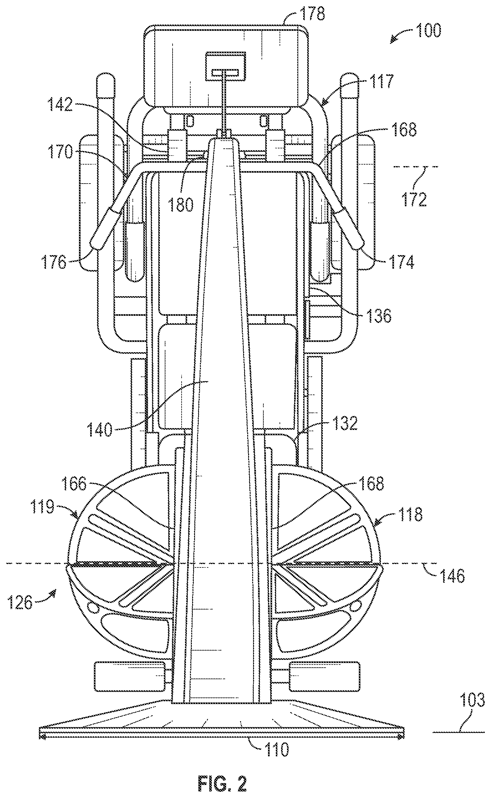
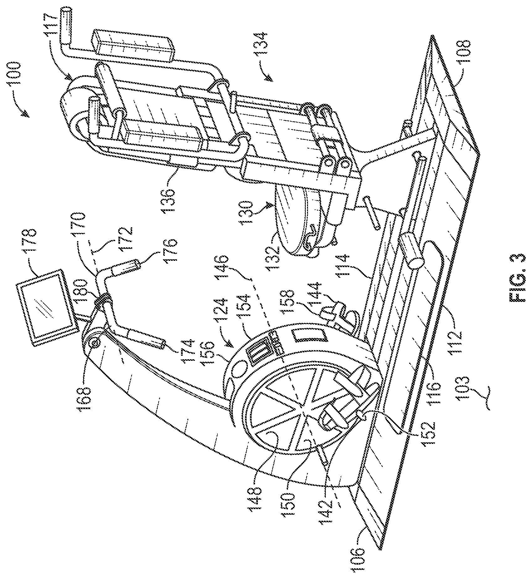
[0078] According to an aspect, the at least one dynamic device 126 can be a cycle mechanism 126. The cycle mechanism 126 can be attached to the base 102 adjacent to the main post 140. In more detail, the cycle mechanism 126 may include at least one pedal 142, 144 that can be configured to allow the user to engage and move the cycle mechanism 126. The at least one pedal 142, 144 of the cycle mechanism 126 can include a first pedal 142 and a second pedal 144. Each pedal 142, 144 may be offset from and rotatable about a cycle axis 146 centrally located in the cycle mechanism 126. Specifically, the cycle axis 146 can extend laterally relative to and can be spaced from the ground surface 103. The cycle axis 146 may also be transverse to a post direction in which the main post 140 extends.
[0079] In one example, the cycle mechanism 126 can also include a first disc 148 that may extend radially from the cycle axis 146 to a first disc perimeter 150. A first pedal axle 152 can extend from the first disc 148. The first pedal axle 152 may extend along and be offset from the cycle axis 146. Therefore, the first pedal axle 152 can be configured to rotatably support the first pedal 142. Similarly, the cycle mechanism 126 can also include a second disc 154 that may extend radially from the cycle axis 146 to a second disc perimeter 156. The second disc 154 can be spaced axially from the first disc 148. A second pedal axle 158 can extend from the second disc 154. The second pedal axle 158 may extend along and be offset from the cycle axis 146. Thus, the second pedal axle 158 can be configured to rotatably support the second pedal 144. As an alternative to the first disc 148 and the second disc 154, the cycle mechanism 126 may include a shaft that rotates in a circle, along which the pedals 142, 144 may transition to different positions.
[0080] In an alternative embodiment, the first disc 148 may also include a first semicircular panel 118 that can be hinged from and rotatable about a first centerline 162 of the first disc 148. The first centerline 162 can be centrally located and can extend laterally relative to and can be spaced from the ground surface 103. Therefore, the first semicircular panel 118 can be movable to a first panel extended position. To facilitate osteogenesis in the user, the user may place their foot on the first semicircular panel 118 in such a position. Likewise, the second disc 154 may also include a second semicircular panel 119 that can be hinged from, and rotatable about a second centerline 166 of the second disc 154. As with the first centerline 162 of the first disc 148, the second centerline 166 can be centrally located and can extend laterally relative to and can be spaced from the ground surface 103. Thus, the second semicircular panel 119 can be movable to a second panel extended position. While the second semicircular panel 119 is in the second panel extended position, the user may place their foot thereon for facilitating osteogenesis.
[0081] In some embodiments, the exercise machine 100 can also include a lateral bar 120 that may be coupled to the distal post end 142 of the main post 140. The lateral bar 120 can extend laterally relative to and be spaced from the ground surface 103. The lateral bar 120 can extend from a first lateral bar end 168 to a second lateral bar end 170 to define a lateral bar axis 172. The lateral bar axis 172 may be orthogonal to the post direction of the main post 140. The lateral bar 120 may include a first bar handle 174 that can extend from the first lateral bar end 168. As a result, the first bar handle 174 can be transverse to the lateral bar axis 172. The lateral bar 120 may also include a second bar handle 176 that may extend from the second lateral bar end 170. Thus, the second bar handle 176 can be transverse to the lateral bar axis 172. To facilitate osteogenesis, the first bar handle 174 and second bar handle 176 can be configured for the user to place their respective hands thereon.
[0082] According to an aspect, the exercise machine 100 can further include a control console 178. The control console 178 can provide information to and instruct the user regarding use of the exercise machine 100. Such information and instructions may be provided to the user prior to, during, and/or after an exercise. This could include information on how to perform the exercise, feedback regarding how much force is being applied, a target force to be applied, historical information for the user about how much force they applied at prior sessions, comparisons to averages, etc. The control console 178 may have any combination of memory storage such as random-access memory (RAM) or read-only memory (ROM). The control console 178 may also include processing resources or a microcontroller or central processing unit (CPU) or hardware or software control logic to provide information to and instruct the user regarding use of the exercise machine 100. However, it is to be appreciated that the processing resources, microcontroller, or CPU may be located anywhere in the exercise machine 100. For example, the processing resources, microcontroller, or CPU may be located in a control box. Additionally, the control console 178 may include one or more wireless, wired or any combination thereof of communications ports. Such communication ports can enable communication with external resources as well as with various input and output (I/O) devices, such as a keyboard, a mouse, pointers, touch controllers, cell phone, personal electronic device and display devices. The control console 178 may also include one or more buses operable to transmit communication of management information between the various hardware components. Finally, the control console 178 can communicate using wire-line communication data buses, wireless network communication, or any combination thereof.
[0083] A plurality of load cells 180 can be electrically coupled (e.g., wired or wireless) to the control console 178. The plurality of load cells 180 may be mechanically coupled to the at least one dynamic device 126 and/or the at least one isometric device. The plurality of load cells 180 can sense at least one load during the isometric exercise and the dynamic exercise and may output a signal corresponding to the at least one load. Based on the output signals from the load cells 180, the control counsel 178 can display the output from the load cells 180, and the user, or other person (e.g., a trainer, a nurse, a technician, a rehabilitation specialist, a physician, etc.) may interact with the counsel 178 to select a program or exercise routine to be executed.
[0084] FIG. 5 depicts several options for the plurality of load cells 180. In some embodiments, the load cells 180 can be piezoelectric load cells, such as PACEline CLP Piezoelectric Subminiature Load Washers. In other embodiments, the load cells can be hydraulic load cells, such as Noshok hydraulic load cells. In some versions, the plurality of load cells 180 can include a plurality of strain gauges. Embodiments of the load cells can be bending-type load cells, such as Omega SGN-4/20-PN 4 mm grid, 20 ohm nickel foil resistors. Other examples of the plurality of load cells can be double-beam-type load cells 180a, such as Rudera Sensor RSL 642 strain gauges. Still other embodiments of the plurality of load cells can be half-bridge-type load cells 180b, such as Onyehn 4pcs 50 kg Human Scale Load Cell Resistance Half-bridge/Amplifier Strain Weight Sensors with 1pcs HX711 AD Weight Modules for Arduino DIY Electronic Scale strain gauges. In some embodiments, the load cells can be S-type load cells 180c, such as Sensortronics S-type load cell 60001 load cells. Additionally, the load cells can be button-type load cells 180d, such as Omega LCGB-250, 250 lb capacity load cells. Naturally, the plurality of load cells 180 can comprise combinations of these various examples. The embodiments described herein are not limited to these examples.
[0085] FIGS. 6-7 show a second exemplary embodiment of an exercise machine 200. The exercise machine 200 may share similar aspects to that of the exercise machine 100 discussed above. In addition, the exercise machine 200 may include at least one isometric device 221, 222 and can additionally include at least one dynamic device 226, 228. More specifically, a pair of upper load handles 221 can be located above and in front of the seat 230. In a core-pull-style exercise, the user can apply force to the upper load handles 221, while being constrained in the seat 230 by the fastening system (not shown). In such an exercise, while the lower body of the user is restrained from upward movement by the fastening system, the user can sit in the seat 230, apply the fastening system, hold the pair of upper load handles 221, and pull on the pair of upper load handles 221 with their arms.
[0086] According to an aspect, adjustments can be made to the position of the pair of upper load handles 221. For example, these adjustments can include the height of the pair of upper load handles 221, the distance between the pair of upper load handles 221 and the seat 230. The adjustments may also include the distance between each handle of the pair of upper load handles 221, the angle of the upper load handles 221 relative to the user, etc. In some embodiments, to account for natural differences in limb length or injuries, each handle of the pair of upper load handles 221 can be adjusted separately.
[0087] The exercise machine 200 may also include a pair of middle load handles 222 that can be spaced apart from and in the front of the seat 230. In a chest-press-style exercise, while seated, the user can apply force to the pair of middle load handles 222. In such an exercise, the user can sit in the seat 230, hold the pair of middle load handles 222, and push against the pair of middle load handles 222 with their arms.
[0088] According to an aspect, adjustments can be made to the position of the pair of middle load handles 222. These adjustments can include the height of the pair of middle load handles 222, the distance between the pair of middle load handles 222 and the seat 230. The adjustments can also include the distance between each handle of the pair of middle load handles 222, the angle of the pair of middle load handles 222 relative to the user, etc. In some embodiments, to account for natural differences in limb length or injuries, each handle of the pair of middle load handles 222 can be adjusted separately. Feedback and instructions can be provided to the user with the control console 278 based on one or more signals from the plurality of load cells 280.
[0089] FIGS. 8-13 show a third exemplary embodiment of an exercise machine 300. The exercise machine 300 can include a first pivoting assembly 323 that may be coupled to and pivotable about a lateral pivoting axis 381 at the distal post end 342. The first pivoting assembly 323 can have a first pivoting arm 382 that may extend therefrom, and the first pivoting arm 383 can have a proximal first arm end 383 and a distal first arm end 384. A first pivoting handle 385 can be pivotally attached to the distal first arm end 384. The exercise machine 300 may also include a second pivoting assembly 324 that can be coupled to and pivotable about the lateral pivoting axis 381 at the distal post end 342. The second pivoting assembly 342 can have a second pivoting arm 386 that may extend from the lateral pivoting axis 381, and the second pivoting arm 386 can have a proximal second arm end 387 and a distal second arm end 388. A second pivoting handle 389 can be pivotally attached at the distal second arm end 388. The first pivoting handle 385 and the second pivoting handle 389 can be configured to be engaged by gripping by the user to facilitate at least one of osteogenesis and muscle hypertrophy.
[0090] As best shown in FIG. 9, in a suitcase-lift-style exercise, the first pivoting handle 385 and the second pivoting handle 389 can be positioned adjacent to the seat 330. In such a position, the user can engage the first and second pivoting handles 385, 389 and pull upwardly to apply a force to the first and second pivoting handles 385, 289 to facilitate at least one of osteogenesis and muscle hypertrophy. It should be appreciated that the first and second pivoting assemblies 323, 342 can be pivoted between a plurality of positions to allow for the user to perform various other exercises. Such exercise can include, but is not limited to standing curls (FIG. 10), leg presses (FIG. 11), bench presses (FIG. 12), and pull downs (FIG. 13). A cycle mechanism 326 may also be provided to enable the user to perform a cycling exercise.
[0091] FIGS. 14-20 show a fourth exemplary embodiment of an exercise machine 400. The exercise machine 400 may include at least one dynamic device 426, 428 and at least one isometric device 423, 424, 425. Specifically, the at least one dynamic device 426, 428 of the exercise machine 400 can include at least one flexible band 428. The at least one flexible band 428 may be configured to be selectively engaged and provide resistance to the user. The at least one flexible band 428 can, for example, stretch between the dynamic device 426, 428 and the seat 430. It is also contemplated that the at least one flexible band 428 can provide resistance to a sliding movement of the seat 430. As best shown in FIGS. 14 and 15, the at least one flexible band 428 can also be attached between the seat 430 and the back portion 434 to provide resistance for crunch-type dynamic exercises. Alternatively, or in addition to the at least one flexible band 428, the at least one dynamic device 428 may include an active resistance device to selectively engage and provide resistance to the user.
[0092] The exercise machine 400 can further include one or more foot plates 425 (e.g., two shown) coupled to the base 402, and each foot plate 425 is configured to be selectively engaged by the user. Each foot plate 425 can be coupled to at least one load cell 480 (e.g., four per foot plate). Accordingly, and with reference to FIG. 16, when the user engages each foot plate 425, each foot plate 425 can be used for a separate and independent measurement of left and right leg forces to facilitate osteogenesis and/or hypertrophy. The foot plates 425 may be used for difference type of exercises, including but not limited to, a leg-press-type exercise (FIG. 16) and a rowing-type exercise (FIG. 17).
[0093] It is to be appreciated that adjustments can be made to the positions of the foot plates 425. The position of the foot plates 425 can be adjustable in a horizontal and/or vertical dimension. Also, the angle of the foot plates 425 relative to the seat or back portion 434 may be adjustable. Examples of how adjustments to the foot plates 425 can be implemented include, but are not limited to, using telescoping tubes and pins, hydraulic pistons, and electric motors. In some embodiments, the foot plates are additionally retractable. Accordingly, the foot plates 425 can fold from an engaged position (FIGS. 16 and 17) to a stored position (FIGS. 14-15, 19, and 20).
[0094] FIGS. 21-26 show a fifth exemplary embodiment of an exercise machine 500 for exercising at least one body part of a user. The exercise machine 500 can include at least one dynamic device 528 (see, FIG. 22) and at least one isometric device 521, 525. As with some of the embodiments described above, the exercise machine 500 can include the pair of upper load handles 521 and the pair of middle load handles 522. The upper load handles 521 and middle load handles 522 may not only be used for isometric exercises enabling bone osteogenesis, but may also be employed for various dynamic exercises enabling muscle hypertrophy. As best shown in FIG. 22, the at least one flexible band 528 can engage the pair of upper load handles 521 to provide a dynamic pull-down-type exercise. As best shown in FIG. 24, the at least one flexible band 528 can engage the base 502 to be used in a dynamic standing-lift-type exercise. FIGS. 25 and 26 show the at least one flexible band 528 can be attached between the seat 530 and the back portion 534 to provide resistance for dynamic crunch-type and back-extension-type exercises. In each exercise, based on one or more signals from the plurality of load cells 580, the control console 578 can provide feedback to the user such as a target pressure and pressure achieved.
[0095] FIGS. 27-28 show a sixth exemplary embodiment of an exercise machine 600 for exercising at least one body part of a user. The exercise machine 600 is separable into a machine representative of the exercise machine 500. In addition, a separable portion 690 may be selectively coupled to the exercise machine 500. The separable portion 690 can include a second main post 691 and may also include the cycle mechanism 626 adjacent to the second main post 691. In more detail, the cycle mechanism 626 may include at least one pedal 642, 644 that can be configured to allow the user to engage and rotate the cycle mechanism 626, as described above. The additional portion 690 of exercise machine 600 can also include a first pivoting assembly 623 and a second pivoting assembly 624 coupled to a pivotable about the second main post 691. Such an arrangement is analogous to what is described above for exercise machine 300. Based on one or more signals from the plurality of load cells 680, the control console 678 can provide feedback to the user, such as a target pressure and pressure achieved.
[0096] The present disclosure further comprises a method of using an exercise machine for enabling a user to exercise. A step of the method can be providing an exercise machine having an isometric device and a dynamic device. Such a machine can be like the machines 100-600 described above. Another step of the method can be selectively engaging at least one of the isometric device and dynamic device. Yet another step of the method can be receiving to at least one of the isometric and dynamic devices an application of force by the user sufficient to facilitate at least one of osteogenesis and muscle hypertrophy.
[0097] FIGS. 29-51 illustrate embodiments of an osteogenic, isometric exercise and rehabilitation system and assembly. An aspect of the disclosure includes an isometric exercise and rehabilitation system or assembly 1100. The assembly 1100 can include a frame 1102. The assembly 1100 can further include one or more pairs of load handles 1104, 1106, 1108 (e.g., three shown) supported by the frame 1102. Each load handle in one of the pairs of load handles 1104, 1106, 1108 can be symmetrically spaced from each other relative to a vertical plane of the assembly 1100. For example, the vertical plane can bisect the assembly 1100 in a longitudinal direction.
[0098] During exercise, a user can grip and apply force to one of the pairs of load handles 1104, 1106, 1108. The term "apply force" can include a single force, more than one force, a range of forces, etc. Each load handle in the pairs of load handles 1104, 1106, 1108 can include at least one load cell 1110 for separately and independently measuring a force applied to respective load handles.
[0099] The placement of a load cell 1110 in each pair of load handles 1104, 1106, 1108 can provide the ability to read variations in force applied between the left and right sides of the user. This allows a user or trainer to understand relative strength. This is also useful in understanding strength when recovering from an injury.
[0100] In some embodiments, the assembly 1100 can further include a computer (not shown). One or more of the load cells 1110 can be individually in electrical communication (or other types of communication) with the computer. In some embodiments, the assembly 1100 can further include a graphical display monitor in electrical communication with the computer for providing information to the users. The information can include how to perform exercises, how much force is being applied, a target force to be applied, historical information for the user about how much force they applied during prior sessions, comparisons to averages, etc. Other types of communication may include mechanical, electromechanical, optical, hydraulic, etc.
[0101] In some embodiments, the assembly 1100 further includes a seat 1112 supported by the frame 1102 in which a user sits while applying force to the load handles. In some embodiments, the seat 1112 can include a support such as a back rest or backboard 1114. In some embodiments, the position of the seat 1112 is adjustable in a horizontal and/or vertical dimension. In some embodiments, the angle of the seat 1112 is adjustable. In some embodiments, the angle of the backboard 1114 is adjustable. Examples of how adjustments to the seat 1112 and backboard 1112 can be implemented include, but are not limited to, using telescoping tubes and pins, hydraulic pistons, electric motors, etc. In some embodiments, the seat 1112 can further include a fastening system 1116 (FIG. 34), such as a seat belt, for securing the user to the seat 1112.
[0102] In one example, the seat 1112 can include a base 1113 that is slidably mounted to a horizontal rail 1111 of the frame 1102. The seat 1112 can be selectively repositionable and secured as indicated by the double-headed arrow. In another example, the seat 1112 can include one or more supports 1117 (e.g., two shown) that are slidably mounted to a substantially vertical rail 1115 of the frame 1102. The seat 1112 can be selectively repositionable and secured as indicated by the double-headed arrow.
[0103] In some embodiments, a first pair of load handles 1104 can be located above and in front of the seat 1112. The user can apply force to the load handles 1104 while being constrained in the seat 1112 by the fastening system 1116 in a core-pull-style exercise. The core-pull-style exercise can provide or enable osteogenesis, bone growth or bone density improvement for a portion of the skeletal system of the user. In a core-pull-style exercise, while the lower body of the user is restrained from upward movement by the fastening system 1116, the user can sit in the seat 1112, apply the fastening system 1116, hold the first pair of load handles 1104, and pull on the first pair of load handles 1104 with their arms.
[0104] In some embodiments, adjustments can be made to the position of the first pair of load handles 1104. For example, these adjustments can include the height of the first pair of load handles 1104, the distance between the first pair of load handles 1104 and the seat 1112, the distance between each handle of the first pair of load handles 1104, the angle of the first load handles 1104 relative to the user, etc. In some embodiments, to account for natural differences in limb length or injuries, each handle of the first pair of load handles 1104 can be adjusted separately.
[0105] In one example, the first pair of load handles 1104 can include a sub-frame 1103 that is slidably mounted to a vertical rail 1105 of the frame 1102. The first pair of load handles 1104 can be selectively repositionable and secured as indicated by the double-headed arrow.
[0106] In some embodiments, a second pair of load handles 1106 can be spaced apart from and in the front of the seat 1112. While seated (FIGS. 33 and 43), the user can apply force to the second pair of load handles 1106 in a chest-press-style exercise. The chest-press-style exercise can provide or enable osteogenesis, bone growth or bone density improvement for another portion of the skeletal system of the user. In a chest-press-style exercise, the user can sit in the seat 1112, hold the second pair of load handles 1106, and push against the second pair of load handles 1106 with their arms.
[0107] In some embodiments, adjustments can be made to the position of the second pair of load handles 1106. These adjustments can include the height of the second pair of load handles 1106, the distance between the second pair of load handles 1106 and the seat 1112, the distance between each handle of the second pair of load handles 1106, the angle of the second load handles 1106 relative to the user, etc. In some embodiments, to account for natural differences in limb length or injuries, each handle of the second pair of load handles 1106 can be adjusted separately.
[0108] In one example, the second pair of load handles 1106 can include the sub-frame 1103 that is slidably mounted to the vertical rail 1105 of the frame 1102. The sub-frame 1103 can be the same sub-frame 1103 provided for the first pair of load handles 1104, or a different, independent sub-frame. The second pair of load handles 1106 can be selectively repositionable and secured as indicated by the double-headed arrow.
[0109] In some embodiments (FIGS. 35, 36 and 45), a third pair of load handles 1108 can be located immediately adjacent the seat 1112, such that the user can stand and apply force in a suitcase-lift-style exercise. The suitcase-lift-style exercise can provide or enable osteogenesis, bone growth or bone density improvement for still another portion of the skeletal system of the user. Examples of the third pair of load handles 1108 can extend horizontally along a pair of respective axes that are parallel to the vertical plane. The third pair of load handles 1108 can be horizontally co-planar, such that a user can apply force to them in a suitcase-lift-style exercise. In the suitcase-lift-style exercise, the user can stand on the floor or a horizontal portion of the frame 1102, bend their knees, grip the third pair of load handles 1108, and extend their legs to apply an upward force to the third pair of load handles 1108.
[0110] In some embodiments, adjustments can be made to the position of the third pair of load handles 1108. These adjustments can include the height of the third pair of load handles 1108, the distance between the third pair of load handles 1108 and the seat 1112, the distance between each handle of the third pair of load handles 1108, the angle of the third load handles 1108 relative to the user, etc. In some embodiments, to account for natural differences in limb length or injuries, each handle of the third pair of load handles 1108 can be adjusted separately.
[0111] In one example, each load handle 1108 of the third pair of load handles 1108 can include a sub-frame 1109 that is slidably mounted in or to a vertical tube 1107 of the frame 1102. Each load handle 1108 of the third pair of load handles 1108 can be selectively repositionable and secured as indicated by the double-headed arrows.
[0112] In other embodiments (not shown), the third pair of load handles 1108 can be reconfigured to be coaxial and located horizontally in front of the user along an axis that is perpendicular to the vertical plane. The user can apply force to the third pair of load handles 1108 in a deadlift-style exercise. Like the suitcase-lift-style exercise, the deadlift-style exercise can provide or enable osteogenesis, bone growth or bone density improvement for a portion of the skeletal system of the user. In the deadlift-style exercise, the user can stand on the floor or a horizontal portion of the frame 1102, bend their knees, hold the third pair of load handles 1108 in front of them, and extend their legs to apply an upward force to the third pair of load handles 1108. In some embodiments, the third pair of load handles 1108 can be adjusted (e.g., rotated) from the described coaxial position used for the deadlift-style exercise, to the parallel position (FIGS. 35, 36 and 51) used for the suitcase lift-style exercise. The third pair of load handles 1108, or others, can be used in a grip strengthening-style exercise to improve strength in the muscles of the hand and forearm.
[0113] The isometric exercise and rehabilitation equipment of the disclosure may separately measure forces exerted by both the left and right sides of the user to enhance osteogenesis, thereby enabling bone growth. Moreover, one or more haptic devices may be used in the isometric exercise and rehabilitation equipment to provide haptic feedback to the user during an exercise. In some embodiments, the haptic feedback may be provided by the haptic device based on a force measured by a load cell.
[0114] "Haptic feedback" may include, but is not limited to, any movement or activity that is electrically, mechanically, and/or electromechanically generated and capable of being perceived sensorially by a user.
[0115] In some embodiments, the assembly 1100 may further include at least one haptic device 1120 (FIGS. 36-39) configured to provide haptic feedback based on the force measured by at least one of the load cells 1110. In some embodiments, the haptic device 1120 is an eccentric rotating mass vibration motor (as shown in FIGS. 36-39), such as a Precision Microdrives.TM. Model No. 304-108 4 mm Vibration Motor. In some embodiments, the haptic device 1120 is a piezoelectric actuator or a linear resonant actuator, such as a Precision Microdrives.TM. Model No. C10-100 10 mm Linear Resonant Actuator. The haptic feedback may refer to a vibration, force, and/or motion generated by the haptic device 1120 that is experienced by the user during the exercise.
[0116] In some embodiments, the haptic device 1120 is located in load handles 1104, 1106, 1108. In some embodiments, the haptic device 1120 is located in the foot plates 1118. In some embodiments, where there is a single load handle, the haptic device 1120 is located in the single load handle. In some embodiments where there is a single foot plate 1118, the haptic device 1120 is located in the single foot plate. In some embodiments, the haptic device 1120 is located in the seat 1112. In some embodiments, the haptic device 1120 is located in the backrest 1114. In some embodiments, the haptic device 1120 is in communication with the computer.
[0117] In some embodiments, the haptic device 1120 is configured to provide haptic feedback in response to the force measured by one or more of the load cells 1110 exceeding a threshold force. In some embodiments, the threshold force is determined by the computer. In some embodiments, a threshold force is input, such as by a supervisor, a user, an autonomous device, etc. In some embodiments, the haptic device 1120 is configured to provide haptic feedback. In some embodiments, the haptic feedback occurs when the force measured exceeds the threshold force. In some embodiments, the haptic feedback occurs exclusively while the force measured exceeds the threshold force. In some embodiments, the haptic device 1120 provides haptic feedback for a predetermined amount of time. In some embodiments, the amount of time is determined by the computer. In some embodiments, a supervising user (e.g., a trainer) inputs the amount of time. In a preferred embodiment, the haptic device 1120 provides haptic feedback once the force measured exceeds the threshold force and stops providing the haptic feedback once a predetermined amount of time has passed or once the force measured drops below the threshold force.
[0118] In some embodiments, the assembly 1100 has pairs of load handles 1104, 1106, 1108 or pairs of foot plates 1118, with each respective load handle 1104, 1106, 1108 or foot plate 1118 of each pair 1104, 1106, 1108, 1118 having its own respective load cell 1110 or set of load cells 1110 and respective haptic device 1120 or set of haptic devices 1120. In a preferred embodiment, the respective haptic device 1120 provides haptic feedback when the force measured by its respective load cell 1110 or set of load cells 1110 exceeds the threshold force. For instance, when the user is performing a leg press on the assembly 1100 with two foot plates 1118 (a right foot plate and a left foot plate), each having its own respective set of load cells 1110 (a right load cell set and a left load cell set) and respective haptic device 1120 (a right haptic device and a left haptic device), each respective haptic device 1120 may provide haptic feedback when that set of load cells measures a force that exceeds the threshold force. For example, if a threshold force of 200 pounds is set for each foot, the haptic feedback may be provided by the right haptic device 1120 on the right foot plate when the measured by the right load cell set exceeds 200 pounds, independent of how much force was measured by the left load cell set. In yet another embodiment, a seat haptic device 1120 may be located in the frame-supported seat 1112 and provide haptic feedback when both sets of load cells 1110 measure forces exceeding the threshold force and for a pre-determined amount of time.
[0119] FIGS. 37-39 show another example of the third pair of load handles 1108. In this version, a grip 1902 can be coupled to a first rectangular tube 1904. The first rectangular tube 1904 can be coupled with fasteners 1906 to one of the load cells 1110. An opposite end of the load cell 1110 can be coupled with additional fasteners 1906 to a second rectangular tube 1908. A cable 1910 can be coupled to the load cell 1110 and can carry a signal from the load cell 1110 to the computer. In some embodiments, each of the load cells 1110 can be in wireless electrical communication with the computer.
[0120] Embodiments of the isometric exercise and rehabilitation assembly 1100 can further include one or more foot plates 1118 (e.g., two shown) coupled to the frame 1102. Each foot plate 1118 can be coupled to at least one load cell 1110 (e.g., four shown per foot plate 1118) for separately and independently measuring left and right leg forces applied to the foot plate 1118 by the user in a leg-press-style exercise. The leg-press-style exercise can provide or enable osteogenesis, bone growth or bone density improvement for a different portion of the skeletal system of the user.
[0121] In some embodiments, adjustments can be made to the positions of the foot plates 1118. In some embodiments, the position of the footplates 1118 is adjustable in a horizontal and/or vertical dimension. In some embodiments, the angle of the footplates 1118 relative to the seat 1112 or backboard 1114 is adjustable. Examples of how adjustments to the footplates 1118 can be implemented include, but are not limited to, using telescoping tubes and pins, hydraulic pistons, and electric motors. In some embodiments, the foot plates 1118 are retractable. In some embodiments, the foot plates 1118 can fold from an engaged position to a stored position.
[0122] FIG. 40 depicts several options for the load cells 1110. In some embodiments, the load cells 1110 can be piezoelectric load cells, such as PACEline CLP Piezoelectric Subminiature Load Washers. In other embodiments, the load cells 1110 can be hydraulic load cells, such as NOSHOK hydraulic load cells. In some versions, the load cells 1110 can include strain gauges. Embodiments of the strain gauges can be bending-type strain gauges, such as Omega SGN-4/20-PN 4 mm grid, 20 ohm nickel foil resistors. Other examples of the strain gauges can be double-bending-type strain gauges 1202, such as Rudera Sensor RSL 642 strain gauges. Still other embodiments of the strain gauges can be half-bridge-type strain gauges 1204, such as Onyehn 4pcs 50 kg Human Scale Load Cell Resistance Half-bridge/Amplifier Strain Weight Sensors with 1pcs HX711 AD Weight Modules for Arduino DIY Electronic Scale strain gauges. In some embodiments, the strain gauges can be S-type strain gauges 1206, such as Sensortronics S-type load cell 60001 strain gauges. Additionally, the strain gauges can be button-type strain gauges 1208, such as Omega LCGB-250 250 lb Capacity Load Cells. Naturally, the load cells 1110 can comprise combinations of these various examples. The embodiments described herein are not limited to these examples.
[0123] FIGS. 41-51 include an alternate embodiment of an isometric exercise and rehabilitation system or assembly 1200. This version and its components can be similar or even identical to the other embodiments disclosed herein. Alternatively, the isometric exercise and rehabilitation system or assembly 1200 can have additional features and components, as shown. Some of these drawings include renderings of primary and secondary stresses induced on the human skeletal system by each type of associated exercise.
[0124] Other examples can include one or more of the following items.
[0125] 1. An isometric exercise and rehabilitation system, comprising: [0126] a frame; [0127] a pair of load handles configured to be supported by the frame and configured to be gripped and have force applied thereto by a user during an osteogenic exercise, wherein the load handles are symmetrically spaced apart from each other relative to a vertical plane that longitudinally bisects the frame; and [0128] each load handle comprises a load cell configured to measure the force applied to the respective load handle.
[0129] 2. The isometric exercise and rehabilitation system, further comprising a computer and a graphical display monitor, each load cell is configured to individually communicate with the computer, and the graphical display monitor is configured to communicate with the computer to display information to the user about the osteogenic exercise or performance of the user.
[0130] 3. The isometric exercise and rehabilitation system, further comprising a seat configured to couple to the frame to support the user while applying force to the load handles, a position of the seat relative to the frame is adjustable, and the seat comprises a fastening system configured to secure the user in the seat.
[0131] 4. The isometric exercise and rehabilitation system, wherein the pair of load handles is configured to be located above and in front of the seat, such that the user can apply force to the load handles in conjunction with a restraining force on the user by the fastening system in a core-pull-style exercise.
[0132] 5. The isometric exercise and rehabilitation system, wherein a position of the load handles is adjustable in a vertical dimension relative to the seat.
[0133] 6. The isometric exercise and rehabilitation system, further comprising a second pair of load handles configured to be spaced apart from a front of the seat, such that the user can apply force in a chest-press-style exercise.
[0134] 7. The isometric exercise and rehabilitation system, wherein a position of the second pair of load handles is adjustable in a vertical dimension.
[0135] 8. The isometric exercise and rehabilitation system, further comprising a third pair of load handles configured to be located horizontally along a first axis that is perpendicular to the vertical plane, such that the user can apply force in a deadlift-style exercise to the third pair of load handles.
[0136] 9. The isometric exercise and rehabilitation system, wherein a position of the third pair of load handles is adjustable in a vertical dimension.
[0137] 10. The isometric exercise and rehabilitation system, further comprising a fourth pair of load handles configured to be located horizontally along a pair of axes that are parallel to the vertical plane, and the fourth pair of load handles are configured to be horizontally co-planar such that a user can apply force in a suitcase lift-style exercise.
[0138] 11. The isometric exercise and rehabilitation system, wherein a position of the fourth pair of load handles is adjustable in a vertical dimension.
[0139] 12. The isometric exercise and rehabilitation system, further comprising a fifth pair of load handles configured to be horizontally co-planar with each other, and configured to be relocated along a vertical axis between a first position wherein the user can apply force in a suitcase lift-style exercise, and a second position wherein the user can apply force in a deadlift-style exercise.
[0140] 13. The isometric exercise and rehabilitation system, wherein the load cells comprise at least one of bending-type strain gauges, double-bending-type strain gauges, half-bridge-type strain gauges, S-type strain gauges, button-type strain gauges, piezoelectric load cells or hydraulic load cells.
[0141] 14. An isometric exercise and rehabilitation assembly, comprising: [0142] a frame; [0143] a pair of load handles supported by the frame and configured to be gripped and have force applied thereto by a user during an osteogenic exercise, wherein the load handles are spaced apart from each other relative to a vertical plane that longitudinally bisects the frame; [0144] each load handle comprises a load cell configured to measure the force applied to the respective load handle; [0145] a seat coupled to the frame and configured to support the user while applying force to the load handles, a position of the seat relative to the frame is adjustable, and the seat comprises a fastening system configured to secure the user in the seat; [0146] a computer and a graphical display monitor coupled to the frame, each load cell is configured to individually communicate with the computer, and the graphical display monitor is configured to communicate with the computer to display information to the user about the osteogenic exercise or performance of the user.
[0147] 15. The isometric exercise and rehabilitation system, wherein the pair of load handles are located above and in front of the seat, such that the user can apply force to the load handles in conjunction with a restraining force on the user by the fastening system in a core-pull-style exercise, and a position of the load handles is adjustable in a vertical dimension relative to the seat.
[0148] 16. The isometric exercise and rehabilitation system, further comprising a second pair of load handles spaced apart from a front of the seat, such that the user can apply force in a chest-press-style exercise; and [0149] a position of the second pair of load handles is adjustable in a vertical dimension.
[0150] 17. The isometric exercise and rehabilitation system 6, further comprising a third pair of load handles located horizontally along a first axis that is perpendicular to the vertical plane, such that the user can apply force in a deadlift-style exercise to the third pair of load handles; and [0151] a position of the third pair of load handles is adjustable in a vertical dimension.
[0152] 18. The isometric exercise and rehabilitation system, further comprising a fourth pair of load handles located horizontally along a pair of axes that are parallel to the vertical plane, and the fourth pair of load handles are horizontally co-planar such that a user can apply force in a suitcase lift-style exercise; and [0153] a position of the fourth pair of load handles is adjustable in a vertical dimension.
[0154] 19. The isometric exercise and rehabilitation system, further comprising a fifth pair of load handles that are horizontally co-planar with each other, and configured to be relocated along a vertical axis between a first position wherein the user can apply force in a suitcase lift-style exercise, and a second position wherein the user can apply force in a deadlift-style exercise.
[0155] 20. The isometric exercise and rehabilitation system, wherein the load cells comprise at least one of bending-type strain gauges, double-bending-type strain gauges, half-bridge-type strain gauges, S-type strain gauges, button-type strain gauges, piezoelectric load cells or hydraulic load cells.
[0156] 1. An isometric exercise and rehabilitation system, comprising: [0157] a frame;
[0158] foot plates configured to be mounted to the frame and configured to be engaged and have force applied thereto by a user performing an osteogenic exercise; and
[0159] each foot plate is configured to be coupled to at least one respective load cell and configured to separately and independently measure the force applied to the respective foot plate in a leg press-style exercise by the user.
[0160] 2. The isometric exercise and rehabilitation system, further comprising a computer, and the load cells are configured individually communicate with the computer.
[0161] 3. The isometric exercise and rehabilitation system, further comprising a graphic display monitor configured to communicate with the computer and configured to display graphical information to the user about at least one of the osteogenic exercise or a performance of the user.
[0162] 4. The isometric exercise and rehabilitation system, further comprising a seat configured to be coupled to the frame and configured to support the user when the user applies force to the foot plates.
[0163] 5. The isometric exercise and rehabilitation system, wherein a position of the seat relative to the frame is adjustable.
[0164] 6. The isometric exercise and rehabilitation system, wherein the position of the seat is adjustable in at least one of a vertical dimension, a horizontal dimension or an angle of the seat relative to the frame.
[0165] 7. The isometric exercise and rehabilitation system, wherein the seat further comprises a fastening system configured to secure the user to the seat.
[0166] 8. The isometric exercise and rehabilitation system, further comprising a back rest configured to be coupled to the frame adjacent to the seat, and the back rest is configured to engage a back of the user to push against while applying force to the foot plates.
[0167] 9. The isometric exercise and rehabilitation system, wherein a position of the back rest is adjustable in at least one of a vertical dimension, a horizontal dimension or an angle of the back rest relative to the frame.
[0168] 10. The isometric exercise and rehabilitation system, wherein each foot plate is coupled to at least four respective load cells.
[0169] 11. The isometric exercise and rehabilitation system, wherein the load cells comprise strain gauges.
[0170] 12. The isometric exercise and rehabilitation system, wherein the strain gauges comprise bending-type strain gauges.
[0171] 13. The isometric exercise and rehabilitation system, wherein the strain gauges comprise double-bending-type strain gauges.
[0172] 14. The isometric exercise and rehabilitation system, wherein the strain gauges comprise half-bridge-type strain gauges.
[0173] 15. The isometric exercise and rehabilitation system, wherein the strain gauges comprise S-type strain gauges.
[0174] 16. The isometric exercise and rehabilitation system, wherein the strain gauges comprise button-type strain gauges.
[0175] 17. The isometric exercise and rehabilitation system, wherein the load cells comprise piezoelectric load cells.
[0176] 18. The isometric exercise and rehabilitation system, wherein the load cells comprise hydraulic load cells.
[0177] 19. An isometric exercise and rehabilitation assembly, comprising: [0178] a frame;
[0179] foot plates mounted to the frame and configured to be engaged and have force applied thereto by a user performing an osteogenic exercise; [0180] a seat coupled to the frame and configured to support the user while applying force to the foot plates, and a position of the seat is adjustable;
[0181] each foot plate is coupled to a respective load cell for separately and independently measuring the force applied to the respective foot plate in a leg press-style exercise by the user; [0182] a computer operably and individually coupled to each of the load cells; and [0183] a graphic display monitor operably coupled to the computer such that the graphic display monitor displays information to the user about the osteogenic exercise or a performance of the user.
[0184] 20. An isometric exercise and rehabilitation assembly, comprising: [0185] a frame;
[0186] a single foot plate mounted to the frame and configured to be engaged and have force applied thereto in an osteogenic exercise by both legs of a user; [0187] a seat coupled to the frame and configured to support the user while seated and applying force to the single foot plate, and a position of the seat is adjustable;
[0188] the foot plate is coupled to load cells for separately and independently measuring the force applied by respective legs of the user in a leg press-style exercise by the user; [0189] a computer operably and individually coupled to the load cells; and [0190] a graphical display monitor operably coupled to the computer and configured to display information to the user about the osteogenic exercise or a performance of the user.
[0191] 1. An isometric exercise and rehabilitation assembly, comprising:
[0192] a frame;
[0193] at least one load handle supported by the frame, wherein:
[0194] during an osteogenic exercise by a use:
[0195] the at least one load handle is configured to be gripped and have force applied thereto, and
[0196] the at least one load handle comprising at least one load cell configured to measure the force applied to the at least one load handle, and
[0197] at least one haptic device configured to provide, during the osteogenic exercise, haptic feedback based on the force measured by the at least one load cell.
[0198] 2. The isometric exercise and rehabilitation assembly, wherein the at least one haptic device is disposed within the at least one load handle.
[0199] 3. The isometric exercise and rehabilitation assembly, further comprising a computer, and wherein the at least one load cell and the at least one haptic device are in communication with the computer.
[0200] 4. The isometric exercise and rehabilitation assembly, further comprising a monitor that is in electrical communication with the computer, wherein the monitor is configured to display, during the osteogenic exercise, at least one of information pertaining to the osteogenic exercise, or a performance of the user determined based at least partially on the force measured by the at least one load cell.
[0201] 5. The isometric exercise and rehabilitation assembly, wherein the at least one haptic device is further configured to provide the haptic feedback in response to the force exceeding a threshold force.
[0202] 6. The isometric exercise and rehabilitation assembly, wherein the threshold force is determined by the computer.
[0203] 7. The isometric exercise and rehabilitation assembly, wherein the at least one haptic device is further configured to provide the haptic feedback while the force measured by the at least one load cell exceeds the threshold force.
[0204] 8. The isometric exercise and rehabilitation assembly, wherein the at least one haptic device is further configured to provide the haptic feedback for a predetermined duration of time for the haptic feedback.
[0205] 9. The isometric exercise and rehabilitation assembly, wherein the predetermined duration of time for the haptic feedback is determined by the computer.
[0206] 10. The isometric exercise and rehabilitation assembly, further comprising a frame-supported seat on which the user sits while applying, during the osteogenic exercise, the force to the at least one load handle.
[0207] 11. The isometric exercise and rehabilitation assembly, wherein another haptic device is disposed within the frame-supported seat.
[0208] 12. The isometric exercise and rehabilitation assembly, wherein the at least one haptic device is an eccentric rotating mass vibration motor, a linear resonant actuator, or a piezoelectric actuator.
[0209] 13. An isometric exercise and rehabilitation assembly, comprising:
[0210] a frame;
[0211] at least one pair of load handles supported by the frame, wherein:
[0212] during an osteogenic exercise by a user:
[0213] the at least one pair of load handles are configured to be gripped and have force applied thereto,
[0214] load handles in the at least one pair of load handles are symmetrically spaced apart from each other relative to a vertical plane that longitudinally bisects the frame of the isometric exercise and rehabilitation assembly,
[0215] each respective load handle of the at least one pair of load handles comprising at least one load cell configured to measure the force applied to the respective load handle, and
[0216] at least one haptic device configured to provide, during the osteogenic exercise, haptic feedback based on the force measured by the at least one load cell included in the respective load handle.
[0217] 14. The isometric exercise and rehabilitation assembly, wherein the at least one haptic device is disposed within the at least one pair of load handles.
[0218] 15. The isometric exercise and rehabilitation assembly, further comprising a computer, and wherein the at least one load cell included in each respective load handle of the at least one pair of load handles is in communication with the computer.
[0219] 16. The isometric exercise and rehabilitation assembly, further comprising a monitor in electrical communication with the computer, wherein the monitor is configured to display, during the osteogenic exercise, at least one of information pertaining to the osteogenic exercise, or a performance of the user determined based at least partially on the force measured by the at least one load cell included in each respective load handle of the at least one pair of load handles.
[0220] 17. The isometric exercise and rehabilitation assembly, wherein each of the at least one haptic device included in the respective load handle of the at least one pair of load handles is further configured to provide the haptic feedback in response to the force exceeding a threshold force.
[0221] 18. The isometric exercise and rehabilitation assembly, wherein the threshold force is determined by the computer.
[0222] 19. The isometric exercise and rehabilitation assembly, wherein each of the at least one haptic device included in the respective load handle of the at least one pair of load handles is further configured to provide the haptic feedback while the force exceeds the threshold force.
[0223] 20. The isometric exercise and rehabilitation assembly, wherein each of the at least one haptic device included in the respective load handle of the at least one pair of load handles is further configured to provide the haptic feedback for a predetermined duration of time for the haptic feedback.
[0224] 21. The isometric exercise and rehabilitation assembly, wherein the predetermined time is determined by the computer.
[0225] 22. The isometric exercise and rehabilitation assembly, further comprising a frame-supported seat on which the user sits while applying, during the osteogenic exercise, the force to the at least one pair of load handles.
[0226] 23. The isometric exercise and rehabilitation assembly, wherein the at least one haptic device is an eccentric rotating mass vibration motor, a linear resonant actuator, or a piezoelectric actuator.
[0227] 24. An isometric exercise and rehabilitation assembly, comprising:
[0228] a frame;
[0229] foot plates mounted to the frame and coupled to load cells, wherein:
[0230] during an osteogenic exercise by a user:
[0231] the foot plates are configured to be engaged and have force applied thereto,
[0232] each respective foot plate of the foot plates being coupled to at least one respective load cell of the load cells for separately and independently measuring the force applied to the respective foot plate; and
[0233] at least one haptic device configured to provide, during the osteogenic exercise, haptic feedback based on the force measured by the load cells.
[0234] 25. The isometric exercise and rehabilitation assembly, wherein the at least one haptic device is disposed within at least one of the foot plates.
[0235] 26. The isometric exercise and rehabilitation assembly, further comprising a computer, and wherein the load cells and the at least one haptic device are in communication with the computer.
[0236] 27. The isometric exercise and rehabilitation assembly, further comprising a monitor that is in electrical communication with the computer, wherein the monitor is configured to display, during the osteogenic exercise, at least one of information pertaining to the osteogenic exercise, or a performance of the user determined based at least partially on the force measured by the load cells.
[0237] 28. The isometric exercise and rehabilitation assembly, wherein the at least one haptic device is further configured to provide the haptic feedback in response to the force exceeding a threshold force.
[0238] 29. The isometric exercise and rehabilitation assembly, wherein the threshold force is determined by the computer.
[0239] 30. The isometric exercise and rehabilitation assembly, wherein the at least one haptic device is further configured to provide the haptic feedback while the force exceeds the threshold force.
[0240] 31. The isometric exercise and rehabilitation assembly, wherein the at least one haptic device is further configured to provide the haptic feedback for a predetermined duration of time for the haptic feedback.
[0241] 32. The isometric exercise and rehabilitation assembly, wherein the predetermined duration of time for the haptic feedback is determined by the computer.
[0242] 33. The isometric exercise and rehabilitation assembly, further comprising a frame-supported seat on which the user sits while applying, during the osteogenic exercise, the force to the foot plates.
[0243] 34. The isometric exercise and rehabilitation assembly, wherein the at least one haptic device is disposed within the frame-supported seat.
[0244] 35. The isometric exercise and rehabilitation assembly, wherein the at least one haptic device is an eccentric rotating mass vibration motor, a linear resonant actuator, or a piezoelectric actuator.
[0245] 36. An isometric exercise and rehabilitation assembly, comprising:
[0246] a frame;
[0247] a single foot plate mounted to the frame, wherein the single foot plate is configured to be engaged and have force applied thereto during an osteogenic exercise by a user;
[0248] a frame-supported seat on which the user sits while applying the force to the single foot plate, wherein a position of the frame-supported seat is configured to be adjustable, wherein the single foot plate is coupled to a load cell configured to measure the force applied by a leg of the user during the osteogenic exercise;
[0249] a computer operably coupled to the load cell;
[0250] a monitor operably coupled to the computer, wherein the monitor is configured to display at least one of information pertaining to the osteogenic exercise, or a performance of the user based at least partially on the force measured by the load cell; and
[0251] at least one haptic device configured to provide, during the osteogenic exercise, haptic feedback based on the force measured by the load cell.
[0252] 37. The isometric exercise and rehabilitation assembly, wherein the at least one haptic device is disposed within the single foot plate.
[0253] 38. The isometric exercise and rehabilitation assembly, wherein the at least one haptic device is further configured to provide the haptic feedback in response to the force exceeding a threshold force.
[0254] 39. The isometric exercise and rehabilitation assembly, wherein the threshold force is determined by the computer.
[0255] 40. The isometric exercise and rehabilitation assembly, wherein the at least one haptic device is further configured to provide the haptic feedback while the force measured by the load cell exceeds the threshold force.
[0256] 41. The isometric exercise and rehabilitation assembly, wherein the at least one haptic device is further configured to provide the haptic feedback for a predetermined duration of time for the haptic feedback.
[0257] 42. The isometric exercise and rehabilitation assembly, wherein the predetermined duration of time for the haptic feedback is determined by the computer.
[0258] 43. The isometric exercise and rehabilitation assembly, wherein the at least one haptic device is disposed within the frame-supported seat.
[0259] 44. The isometric exercise and rehabilitation assembly, wherein the at least one haptic device is an eccentric rotating mass vibration motor, a linear resonant actuator, or a piezoelectric actuator.
[0260] The various aspects, embodiments, implementations or features of the described embodiments can be used separately or in any combination. The embodiments disclosed herein are modular in nature and can be used in conjunction with or coupled to other embodiments, including both statically-based and dynamically-based equipment. In addition, the embodiments disclosed herein can employ selected equipment such that they can identify individual users and auto-calibrate threshold multiple-of-body-weight targets, as well as other individualized parameters, for individual users.
[0261] This disclosure is meant to be illustrative of the principles and various embodiments. Benefits, other advantages, and solutions to problems have been described above with regard to specific embodiments. However, the benefits, advantages, solutions to problems, and any feature(s) that can cause any benefit, advantage, or solution to occur or become more pronounced are not to be construed as a critical, required, sacrosanct or an essential feature of any or all the claims. Numerous variations and modifications will become apparent to those skilled in the art once the above disclosure is fully appreciated. It is intended that the following claims be interpreted to embrace all such variations and modifications.
* * * * *
D00000
D00001
D00002
D00003
D00004
D00005
D00006
D00007
D00008
D00009
D00010
D00011
D00012

D00013

D00014

D00015

D00016

D00017

D00018

D00019

D00020

D00021
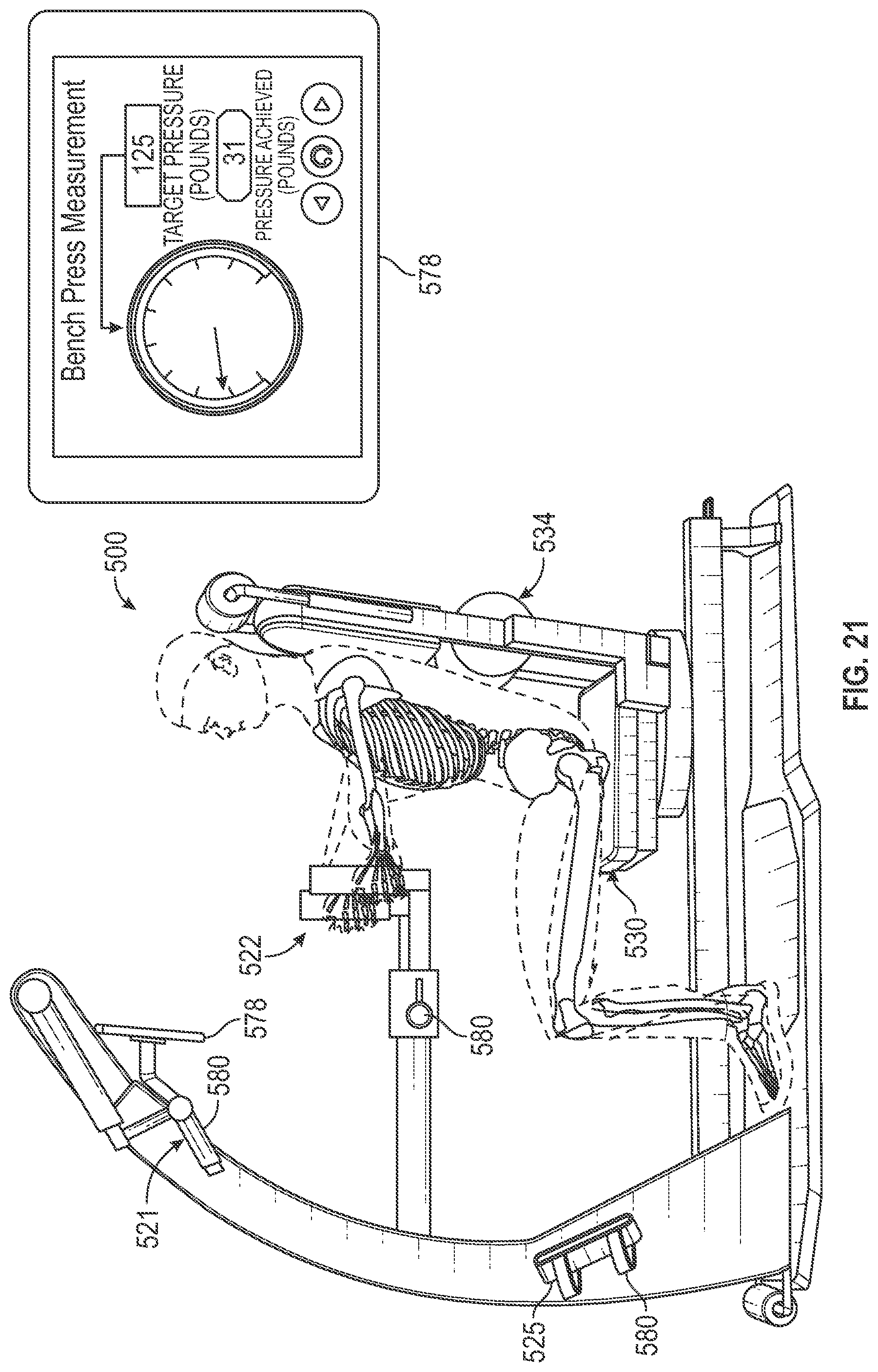
D00022

D00023

D00024
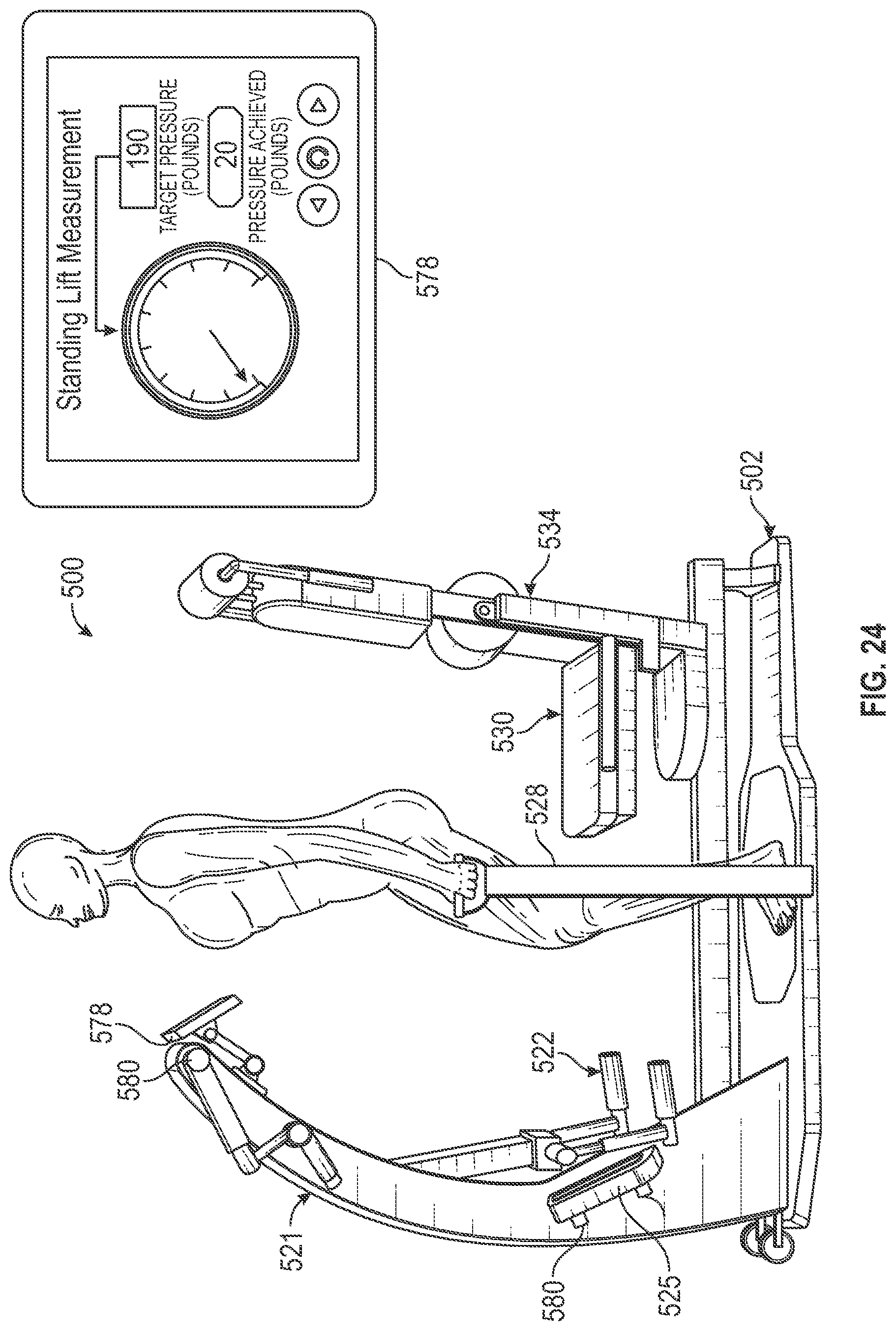
D00025
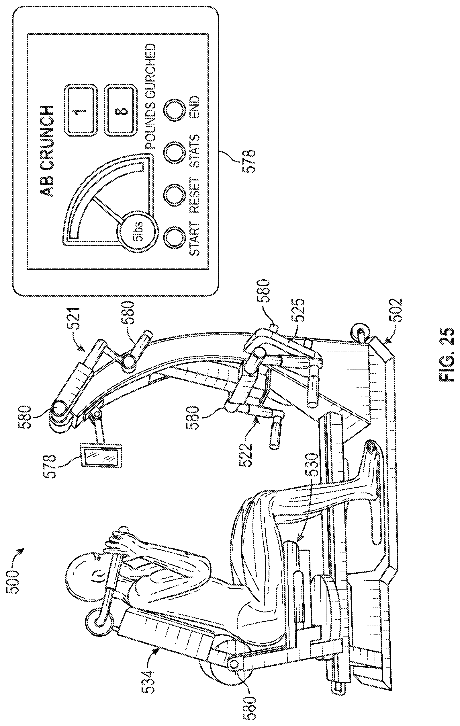
D00026
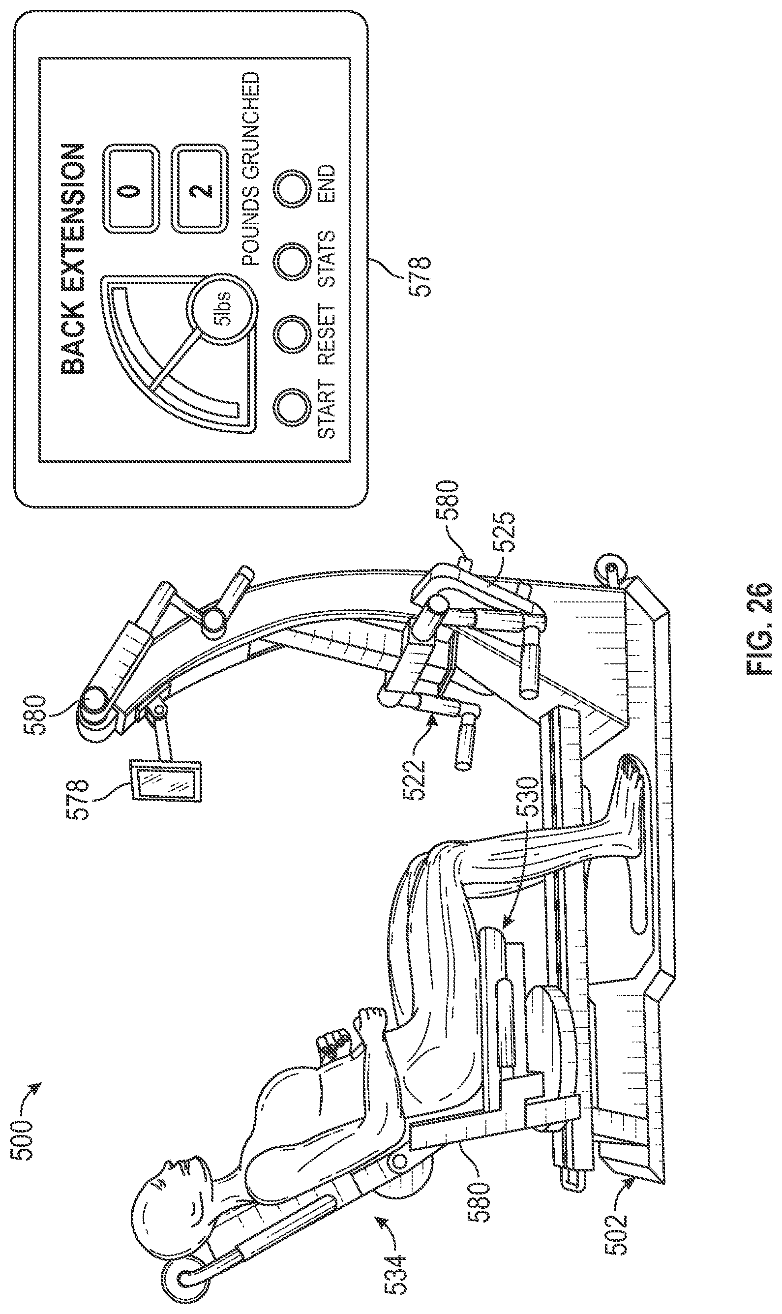
D00027

D00028
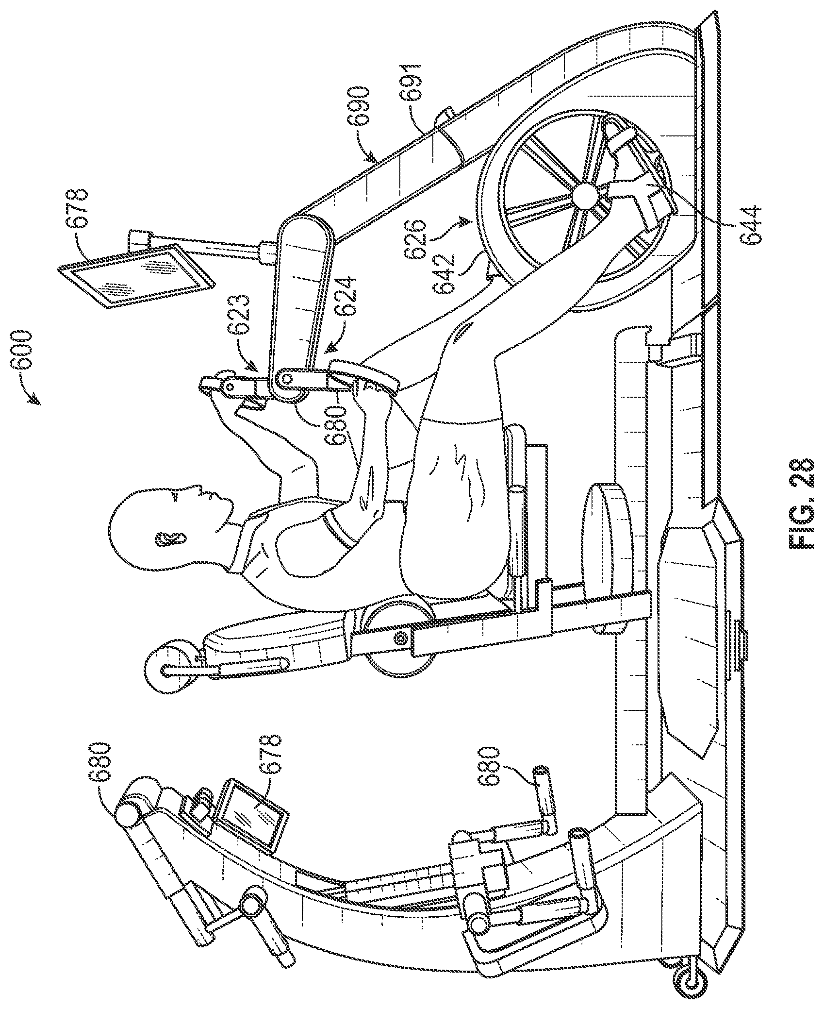
D00029

D00030
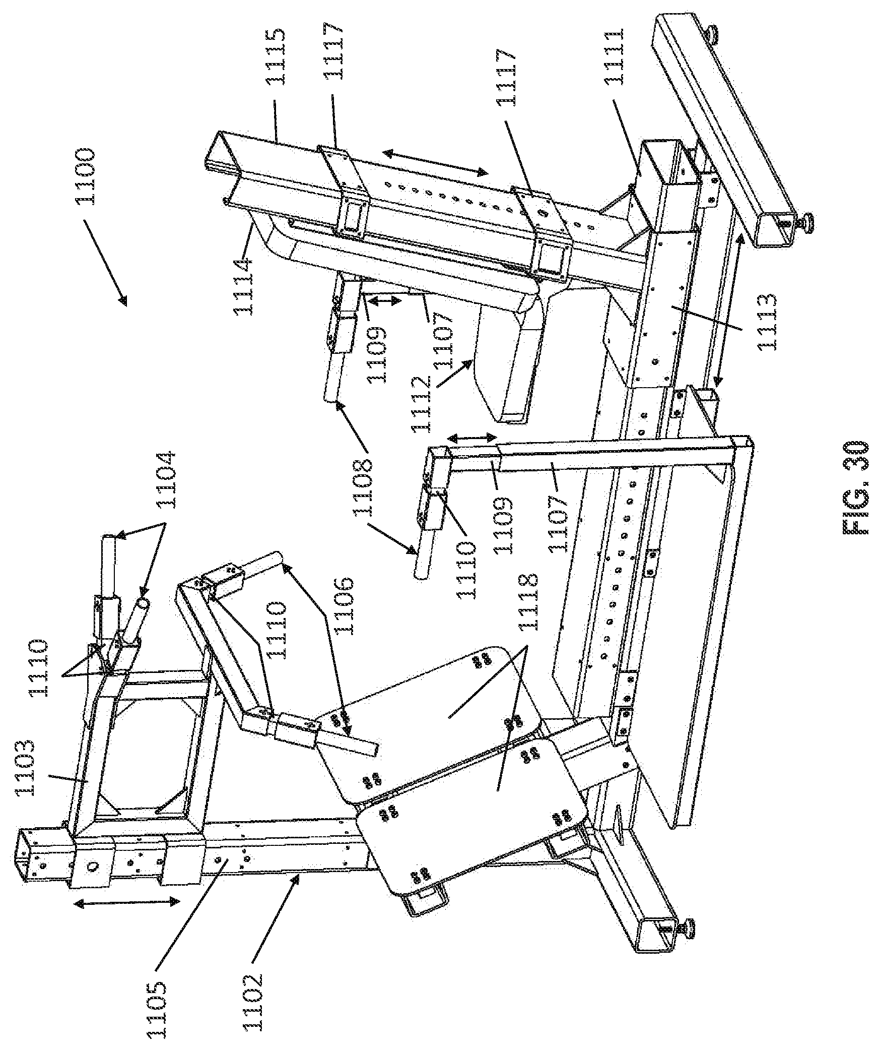
D00031

D00032

D00033
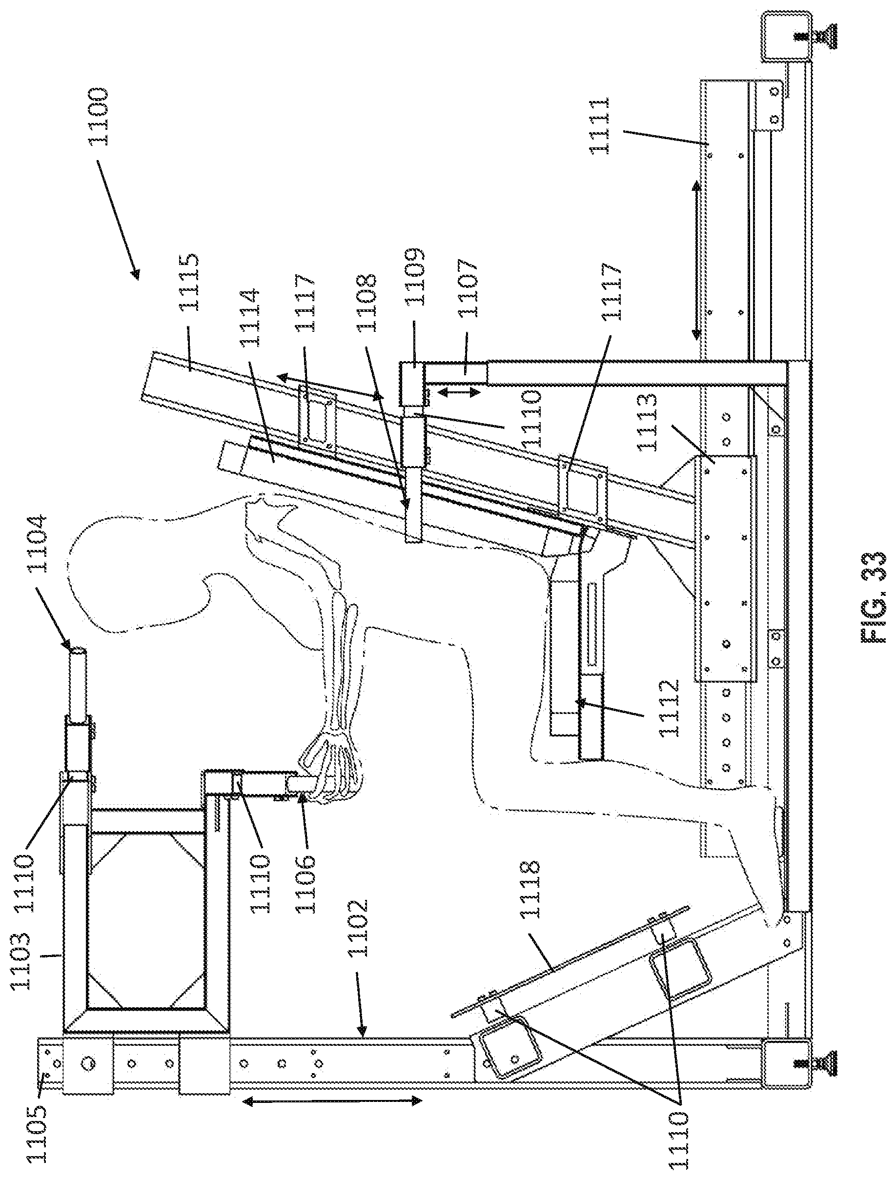
D00034

D00035

D00036
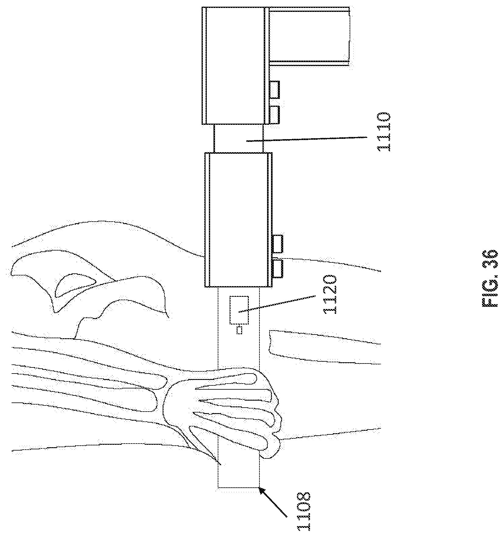
D00037
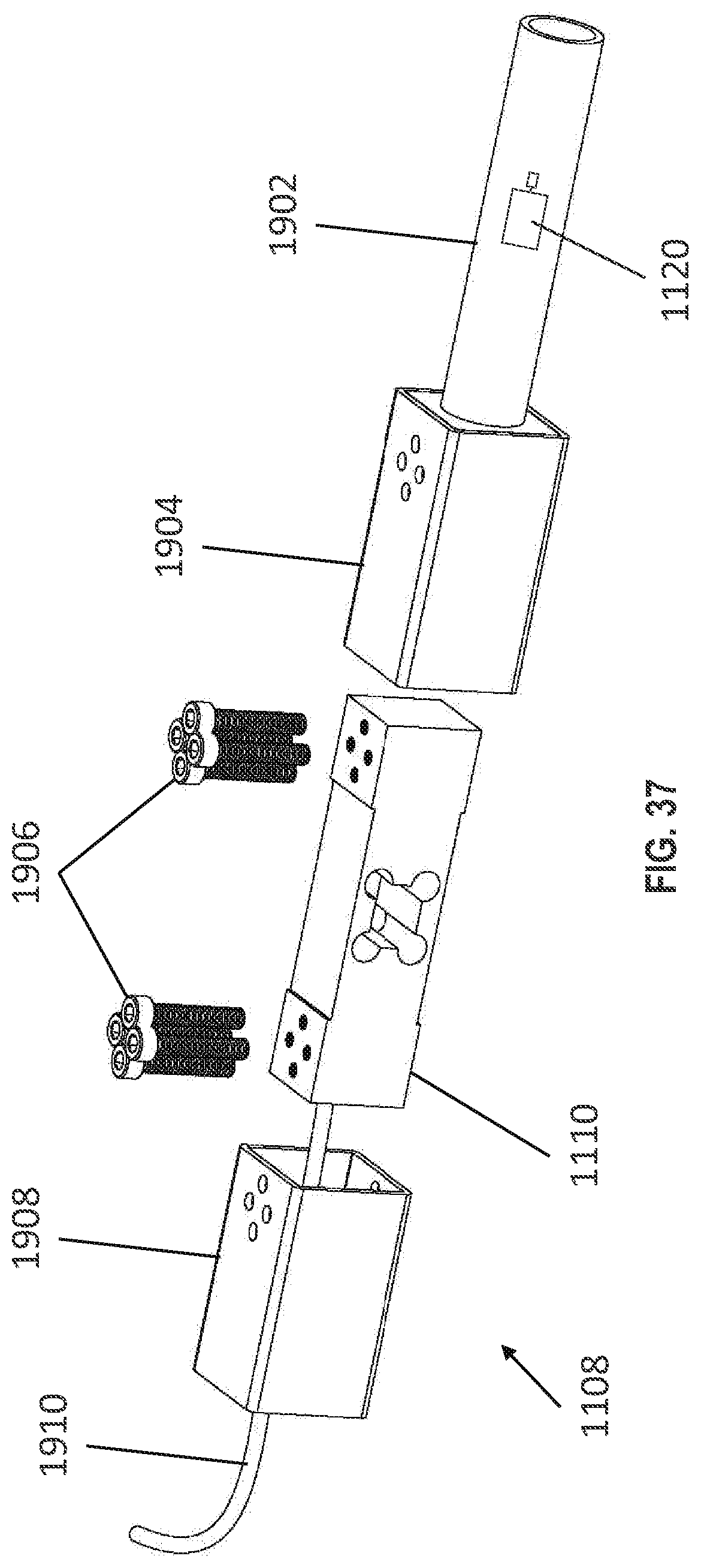
D00038
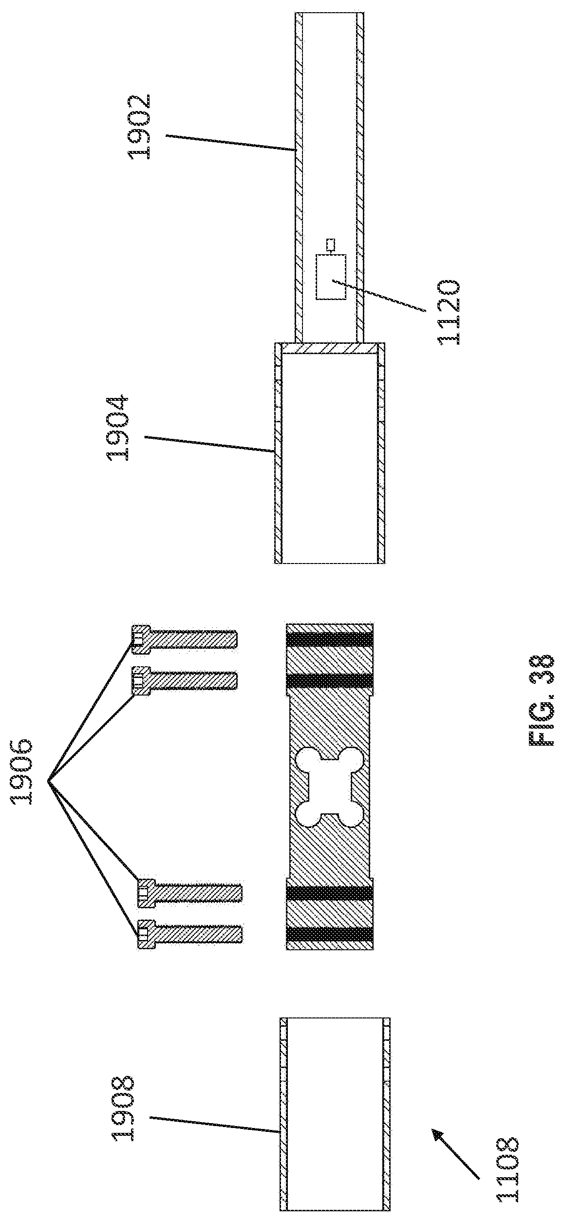
D00039

D00040
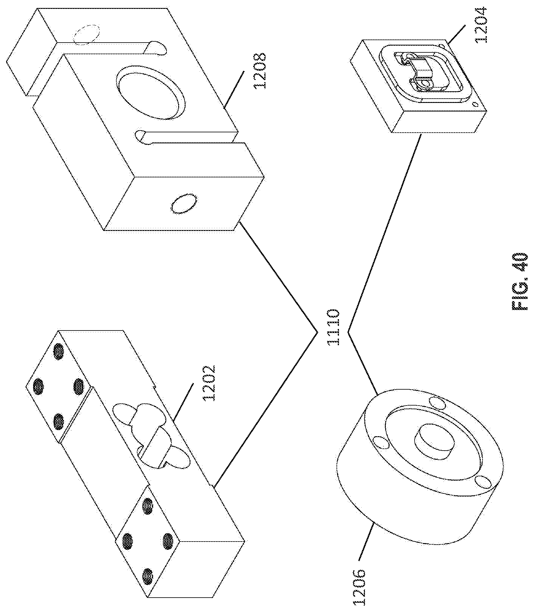
D00041

D00042
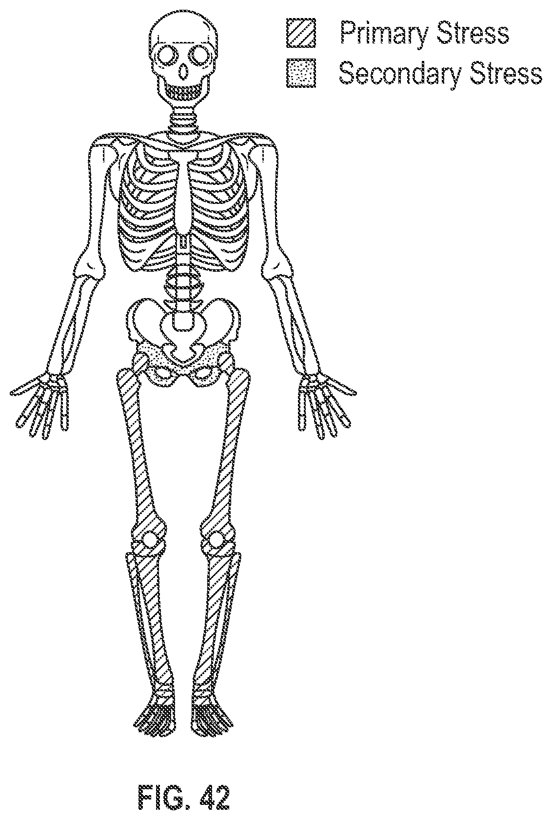
D00043

D00044

D00045

D00046

D00047

D00048

D00049

D00050

D00051

XML
uspto.report is an independent third-party trademark research tool that is not affiliated, endorsed, or sponsored by the United States Patent and Trademark Office (USPTO) or any other governmental organization. The information provided by uspto.report is based on publicly available data at the time of writing and is intended for informational purposes only.
While we strive to provide accurate and up-to-date information, we do not guarantee the accuracy, completeness, reliability, or suitability of the information displayed on this site. The use of this site is at your own risk. Any reliance you place on such information is therefore strictly at your own risk.
All official trademark data, including owner information, should be verified by visiting the official USPTO website at www.uspto.gov. This site is not intended to replace professional legal advice and should not be used as a substitute for consulting with a legal professional who is knowledgeable about trademark law.