Vacuum Closure Device
Greener; Bryan
U.S. patent application number 16/879466 was filed with the patent office on 2020-11-12 for vacuum closure device. The applicant listed for this patent is Smith & Nephew PLC. Invention is credited to Bryan Greener.
| Application Number | 20200353136 16/879466 |
| Document ID | / |
| Family ID | 1000004978016 |
| Filed Date | 2020-11-12 |


View All Diagrams
| United States Patent Application | 20200353136 |
| Kind Code | A1 |
| Greener; Bryan | November 12, 2020 |
VACUUM CLOSURE DEVICE
Abstract
This invention relates to the design of tissue covering elements for use in vacuum assisted tissue apposition systems, wherein the geometry of the covering elements favours the application of contractile forces over compressive or extensive forces at the tissue interface.
| Inventors: | Greener; Bryan; (York, GB) | ||||||||||
| Applicant: |
|
||||||||||
|---|---|---|---|---|---|---|---|---|---|---|---|
| Family ID: | 1000004978016 | ||||||||||
| Appl. No.: | 16/879466 | ||||||||||
| Filed: | May 20, 2020 |
Related U.S. Patent Documents
| Application Number | Filing Date | Patent Number | ||
|---|---|---|---|---|
| 15796441 | Oct 27, 2017 | 10695472 | ||
| 16879466 | ||||
| 14466892 | Aug 22, 2014 | 9801986 | ||
| 15796441 | ||||
| 12922118 | Nov 17, 2010 | 8821535 | ||
| PCT/GB09/00696 | Mar 13, 2009 | |||
| 14466892 | ||||
| Current U.S. Class: | 1/1 |
| Current CPC Class: | A61F 13/00068 20130101; A61M 27/00 20130101; A61M 1/0027 20140204; A61M 1/0023 20130101; A61M 1/0066 20130101; A61M 1/0088 20130101; A61M 1/0009 20130101; A61M 1/0058 20130101; A61M 1/0001 20130101; A61M 1/009 20140204; A61M 1/0011 20130101 |
| International Class: | A61M 1/00 20060101 A61M001/00 |
Foreign Application Data
| Date | Code | Application Number |
|---|---|---|
| Mar 13, 2008 | GB | 0804654.2 |
Claims
1-15. (canceled)
16. A method of closing a wound, the method comprising; locating a tissue stabilizing element at a wound site, the wound site comprising wound margins; applying a negative pressure to the tissue stabilizing element, wherein the tissue stabilizing element under negative pressure exerts a contractile force to the wound margins, drawing the wound margins toward a center of the wound, wherein the tissue stabilizing element contracts more in a direction parallel to a skin surface surrounding the wound than in a direction perpendicular to the skin surface and contracts anisotropically parallel to the skin surface.
17. The method of claim 16, wherein the tissue stabilizing element is placed above the skin surface.
18. The method of claim 16, further comprising forming a vacuum seal at the wound site.
19. The method of claim 16, further comprising connecting a source of negative pressure.
20. The method of claim 16, wherein the tissue stabilizing element comprises a plurality of flat, internal faces.
21. A method of exerting a closing force on a wound, the method comprising; positioning a tissue stabilizing element at a wound site so as to create a substantially sealed space between the tissue stabilizing element and the wound; reducing the pressure in the substantially sealed space between the tissue stabilizing element and the wound, thereby contracting the tissue stabilizing element in a first linear direction that is toward a center or a centerline of the tissue stabilizing element and parallel to the wound surface, wherein the tissue stabilizing element contracts more in a first linear direction that is parallel to the wound surface than in a second linear direction that is parallel to the wound surface, the second linear direction being perpendicular to the first linear direction.
22. The method of claim 21, wherein contracting the tissue stabilizing element exerts a net contractile force on the wound in the first direction.
23. The method of claim 21, further comprising contracting the tissue stabilizing element in the first direction that is toward the center or centerline of the tissue covering element more than in a second direction that is transverse to the first direction, thereby contracting the wound in said first direction more than in said second direction
24. The method of claim 21, wherein the tissue stabilizing element comprises a plurality of flat, internal faces
25. A tissue stabilizing element for use in a vacuum assisted closure system, the tissue stabilizing element comprising: a stabilizing portion comprising a plurality of flat, internal surfaces, the stabilizing portion configured to be positioned at a wound; wherein the stabilizing portion is configured to contract to a greater extent along a first direction relative to a second direction upon application of negative pressure, the first direction parallel to the wound and the second direction perpendicular to the wound; wherein the flat, internal surfaces are configured to collapse toward one another upon application of negative pressure; and wherein the stabilizing portion is configured to apply a closing force to the wound along the first direction.
26. The tissue stabilizing element of claim 25, further comprising a vacuum connection aperture.
27. The tissue stabilizing element of claim 26, wherein the aperture is configured to connect to a conduit, the conduit configured to deliver negative pressure.
28. The tissue stabilizing element of claim 25, wherein the stabilizing portion is configured for placement over the wound.
29. The tissue stabilizing element of claim 25, wherein the stabilizing portion comprises a plurality of angles between the internal surfaces, the angles configured to decrease upon application of negative pressure.
30. The tissue stabilizing element of claim 25, wherein the stabilizing portion is transparent.
Description
CROSS REFERENCE TO RELATED APPLICATIONS
[0001] This application is a continuation of U.S. patent application Ser. No. 14/466,892, filed Aug. 22, 2014, entitled "VACUUM CLOSURE DEVICE," which is a continuation of U.S. patent application Ser. No. 12/922,118, filed Nov. 17, 2010, entitled "VACUUM CLOSURE DEVICE," which is a National Phase Application of PCT Patent Application PCT/GB2009/000696, filed Mar. 13, 2009, entitled "VACUUM CLOSURE DEVICE," which claims priority to Great Britain Application No. 0804654.2, filed Mar. 13, 2008. The contents of the aforementioned applications are hereby incorporated by reference in their entireties as if fully set forth herein. The benefit of priority to the foregoing applications is claimed under the appropriate legal basis, including, without limitation, under 35 U.S.C. .sctn. 119(e).
BACKGROUND OF THE INVENTION
Field of the Invention
[0002] This invention relates to the design of tissue covering elements for use in vacuum assisted tissue apposition systems, wherein the geometry of the covering elements favours the application of contractile forces over compressive or extensive forces at the tissue interface.
Description of the Related Art
[0003] Topical negative pressure (TNP) therapy has rapidly grown to be of excellent utility in the medical field, particularly in the treatment of wounds.
[0004] A number of the current negative pressure systems available involve the application of a porous, deformable wound filler to the wound. The basic principle of TNP therapy is to create a closed cavity over the wound itself by means of a thin, flexible sealing film adhered to the patient's sound skin surrounding the wound; admitting one end of an aspirant conduit into the closed cavity, the conduit being sealed to the flexible film, for example; and connecting a distal end of the aspirant conduit to a vacuum source such as an electrically driven vacuum pump, for example, to create a pressure lower than the surrounding ambient atmospheric pressure within the wound cavity. As is known to the skilled person the lower pressure creates many beneficial therapeutic effects on the wound including increased blood flow to the wound and faster granulation of tissue, for example. When the vacuum pump is switched on, the adjacent surfaces formed cavity expand into the wound filler, compressing it up to the point where it can mechanically resist further deformation. In this state, it is hypothesised that, in a wound cavity, both compressive and extensive forces are exerted on the micro scale at the tissue surface while extensive forces are exerted on the macro scale a short distance from the tissue-filler interface. The extent of these compressive and extensive forces is determined by the applied (negative) pressure, the mechanical properties of the surrounding tissue, filler and drape and the geometry of the wound.
[0005] One TNP system provide the user with sheets of foam of varying geometry that are routinely cut to shape at the site of application to conform to the surface of the wound or fill the wound cavity. In this regard, for some applications, including those targeted here, this technique is sub-optimal. The problem here is that even if we assume uniform foam, drape and tissue mechanics across the patient population, the wound geometry will vary significantly from patient to patient. FIG. 1 demonstrates the effect of applying standard pressure and mechanics (tissue, drape and foam) to varying geometries of application; the force vectors generated vary widely. For most applications, particularly to cavity wounds, the extent of this variation is not great and does not affect the efficacy of the treatment significantly: surrounding tissue is generally expanded in the desired direction, towards the centre line of the cavity volume (see FIG. 1). However, for shallow wounds or incisional wounds, the desired mechanical forces are not afforded by the current method; in general, a compressive force perpendicular to the tissue surface is generated with a minor force generated in the direction parallel to the wound surface. For shallow wounds and incision wounds, it is desirable to generate significant forces parallel to the wound surface in the direction of wound closure in the same way as it is desirable to generate this arrangement in wound cavities by the traditional method.
[0006] We are not aware of topical negative pressure devices capable of generating significant forces parallel to largely two-dimensional surfaces of attachment.
SUMMARY OF THE INVENTION
[0007] The invention is concerned with the component of a topical or internal negative therapy apparatus which forms the interface with the tissue surface and provides a vacuum cavity above the tissue surface. Traditionally, in the field of topical negative pressure, this interface is achieved using a porous wound filler and an occlusive or semi-occlusive adhesive drape (to create the substantially air tight seal), as described above.
[0008] This device is referred to herein as the tissue covering element.
[0009] The invention is not restricted to the means of generating negative pressure or regulating negative pressure or to the means of transmitting the source of negative pressure to the site of application, but is directed to the design geometry of the tissue covering element.
[0010] The comparable component of the present invention in conventional negative pressure systems generates very low contractile forces in the plane which is parallel to largely flat or convex tissue surfaces but, in contrast, generates relatively large compressive or extensive forces in the plane which is perpendicular to the tissue surface. This is because the majority of the surface area of the vacuum cavity arranged in these cases is parallel to the tissue surface and the forces are generated perpendicular to this.
[0011] The force vectors generated are predominantly compressive forces. Such forces are appropriate for the closure of cavity wounds but are contrary to the desire for contraction of the wound margin in the direction of closure for largely flat or convex defects. As FIGS. 1 b and 1 c further illustrate, the generation of significant forces parallel to the tissue surface cannot be achieved easily when the wound covering element is largely parallel to the tissue surface.
[0012] The present invention concerns a tissue covering element that forms an interface with largely flat or convex tissue surface geometries to generate a vacuum cavity having a geometry that is predominantly non-parallel to the tissue surface and as a consequence generates significant forces parallel to the tissue surface when the cavity is placed under reduced pressure. Preferably, the forces generated are in the direction of wound closure. It is recognised here that the `direction of wound closure` should not only consider the geometry of the wound surface but also the mechanical properties of the surrounding tissue (e.g. Langer's lines) that may influence the most desirable geometry of closure forces.
[0013] It should be further noted that the geometry does not exclude the generation of compressive or extensive forces in the plane perpendicular to the tissue surface.
[0014] Thus, according to a first aspect of the invention there is provided a tissue covering element for use in a vacuum assisted closure system, the tissue covering element comprising: [0015] i) a wound contacting surface, said surface being positionable on either side of a wound margin; [0016] ii) a bridging portion which bridges the wound and in use provides at least a partial vacuum above the wound, and wherein the bridging portion comprises a higher ratio of internal surfaces that are aligned substantially nonparallel relative to the wounded tissue surface, to: surfaces that are aligned substantially parallel relative to the wounded contacting surface.
[0017] According to a second aspect of the invention there is provided a method of closing a wound, said method comprising; [0018] i) locating a tissue covering element according to the invention at a wound site such that the bridging element bridges the wound margins; [0019] ii) providing a device for generating a negative pressure; [0020] iii) applying a negative pressure to the tissue covering element in a manner such that the bridging portion of the tissue covering element creates at least a partial vacuum cavity above the wound.
[0021] A method of applying a contractile force to a wound, said method comprising; [0022] i) locating a tissue covering element according the invention at a wound site, such that the bridging element bridges the wound margins; [0023] ii) providing a device for generating a negative pressure; [0024] iii) applying a negative pressure to the tissue covering element in a manner such that the bridging portion of the tissue covering element creates at least a partial vacuum cavity above the wound.
[0025] According to a further aspect of the invention there is provided the use of a device according to the present invention in a vacuum assisted closure apparatus.
[0026] According to a further aspect of the invention there is provided the use of a device according to the present invention in wound therapy.
[0027] According to a further aspect of the invention there is provided the device or use of the device according to the present invention as herein described with reference to the accompanying Examples and Figures.
[0028] The contractile forces so generated, parallel to the tissue surface are transmitted to the tissue margin and this tissue experiences a force directed approximately towards the centre of the vacuum cavity.
[0029] The tissue surfaces can be largely flat or convex.
[0030] The term `largely flat` is herein taken to mean surfaces with vertical dimensions no greater than 20% of the shortest of the other dimensions (FIG. 2).
[0031] The tissue surfaces can be internal or external to the body.
[0032] The tissue surfaces can be on soft tissues (e.g skin, cartilage, tendon, ligament, muscle, fascia) or hard tissues (e.g bone)
[0033] In embodiments of the invention such a surface geometry can be afforded by the use of corrugated or concertina-folded structures. The corrugation of the vacuum cavity cannot easily or painlessly be achieved in the tissue surface but can easily be achieved in the tissue covering element by providing corrugations that extend in the direction largely perpendicular to the tissue surface. It is important that this geometry is not completely destroyed under the influence of reduced pressure within the vacuum cavity, although some geometrical distortion is unavoidable.
[0034] It is important that the covering element is sufficiently flexible to allow good conformability across the tissue but also sufficiently rigid to maintain a higher ratio of surfaces perpendicular to the tissue surface than those parallel to the tissue surface. This combination of flexibility and rigidity can be achieved most simply by combining relatively inflexible surfaces largely perpendicular to the tissue surface with flexible hinges.
[0035] The tissue covering element of the present invention is defined as having at least 50% of its internal surface area distribution at an angle of 450 or greater relative to the underlying, largely flat or convex tissue surface. The net force is contractile.
[0036] In further specific embodiments of the invention the tissue covering element is defined as having at least 50% of its internal surface area distribution at an angle of 800 or greater relative to the underlying, largely flat or convex tissue surface. The net force is contractile.
[0037] There may be some medical applications in which it may be desired to provide a wound covering element that expands rather than contracts the wound. In such instances the tissue covering element defined as having the majority of its internal surface area distribution at an angle of between about 50 to 450 relative to the underlying, largely flat or convex tissue surface.
[0038] The shortest distance between the margins of the wound is defined as X, and the length of the bridging element is defined as Y. In embodiments of the invention Y is at least 110% of X. In further embodiments of the invention Y is at least 141% of X, as illustrated in FIG. 5. The tissue covering element can be defined in any single dimension as one with an internal surface length not exceeding 1000% of the shortest line between opposing pOints on the tissue margin (FIG. 5). The additional surface length is used to generate corrugations or folds that increase the surface area of the covering non-parallel to the tissue surface with the aim of maximising the perpendicularity of the covering to the tissue surface.
[0039] For application to largely one-dimensional incision wounds, an inverted `V` structure, as illustrated in FIG. 3c, is an advantageous geometry.
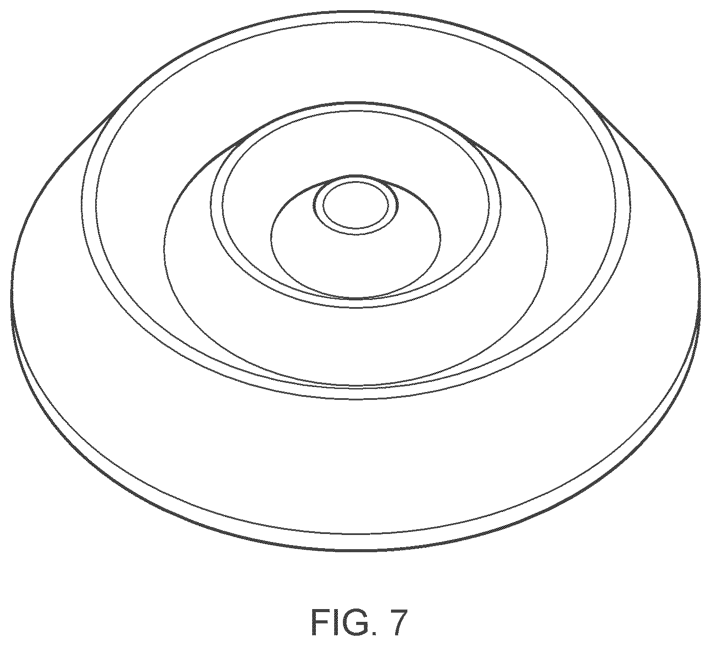
[0040] For application to largely flat circular wounds in locations of isotropic skin tension, a corrugated concentric ring structure, as illustrated in FIG. 7, is an advantageous geometry.
[0041] For application to large flat wounds in locations of anisotropic skin tension, a multiple inverted `V` `concertina configuration in desirable. The lines of the concertina folds being positioned parallel to local Langer's lines to effect wound closure (FIG. 8).
[0042] For example, for application to convex surfaces, such as the extremities of the body or the bones of the body, a cylindrical concertina configuration is desirable (similar to a shock absorber `boot`). The lines of the concertina folds being perpendicular to the axis of the limb (FIG. 9) for application to bone, or parallel to local Langer's lines to effect topical wound closure (FIG. 8).
[0043] In practical use, to avoid the eventuality where the application of negative pressure to the cavity causes gross distortion of the desired geometry of the covering, the two-dimensional surfaces of the device are constructed of relatively stiff materials in comparison to the folded regions, which should flex easily. That is not to imply the use of rigid materials, uncomfortable for the wearer.
[0044] The tissue covering element must be attached to the patient in a manner that creates an substantially air tight seal of a quality that allows the vacuum source to maintain the target vacuum level within the enclosed volume. Practically, attachment to the patient can be achieved by means of any bonding mechanism. Preferably attachment is achieved by using an adhesive, such as an acrylate- or silicone-based adhesive commonly used for the attachment of medical devices and well known in the art. It is also possible that attachment can be achieved by utilising the pressure differential alone, in the same manner as a suction cup. However, this is difficult to achieve in reality due to the mechanical properties of tissue. Connection of the enclosed volume to the vacuum source can be achieved by any means obvious to a person skilled in the art, for example via a central penetrating port or in between the covering element and the bonded perimeter. Preferably, the vacuum source is connected to the enclosed volume by a port penetrating the surface of the covering element. It is additionally beneficial for the coupling of the vacuum source to the covering element to be achieved by a reversible means to facilitate repeated connection and disconnection over the duration of dressing wear. It is also preferable that connection and disconnection can be easily achieved by the patient and applier.
[0045] The invention is not restricted to filling elements that may optionally be positioned within the vacuum enclosure.
[0046] The devices so described can be applied in a range of medical applications where generation of forces parallel to a surface of attachment is desirable for example, the joining of tissue and bone lesions or defects. Both topical and internal applications can be foreseen, from the application of contractive force to bone breaks to the closure of surface wounds, including surgical incisions.
BRIEF DESCRIPTION OF THE DRAWINGS
[0047] The invention will now be described, for illustrative purposes only, with reference to the accompanying Examples and Figures, wherein the Figures illustrate:
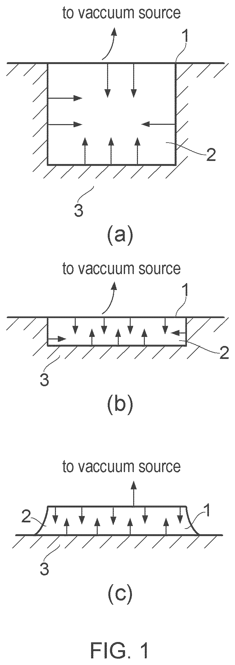
[0048] FIG. 1: Force vectors generated within hypothetical tissue cavities. [0049] (a) Force vectors generated by a conventional tissue covering element when applied to (a) a cavity wound (b,c) and to a largely flat or convex wound.
[0050] FIG. 2: Illustrates a substantially flat wound.
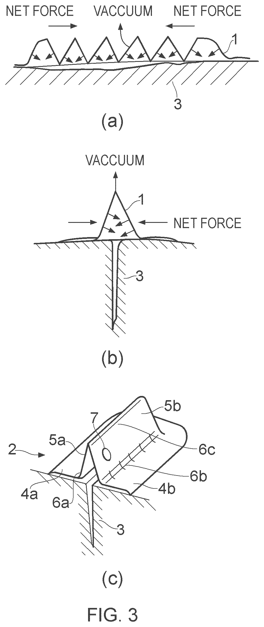
[0051] FIG. 3: Embodiments of the tissue covering element of the present invention.
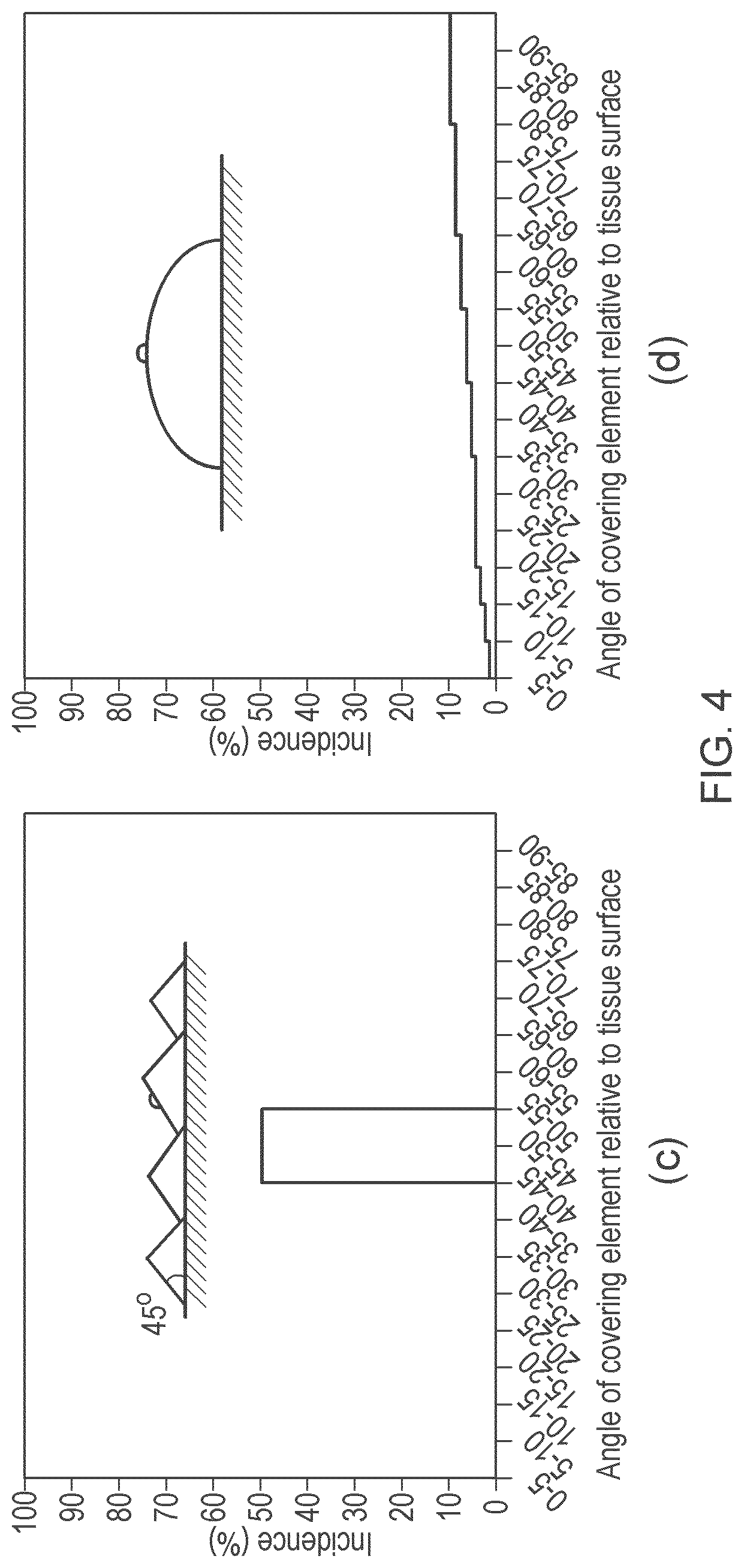
[0052] FIG. 4: The distribution of surface area angles for any given tissue covering element can be represented in a histogram.
[0053] FIG. 5: Determining the optimal dimension of the tissue covering element.
[0054] FIG. 6: Relationship between the dimension of the tissue covering element and the forces generated.
[0055] FIG. 7: A schematic of tissue covering element for application to largely flat circular wounds in locations of isotropic skin tension.
[0056] FIG. 8: A schematic of tissue covering element for application to largely flat wounds in locations of anisotropic skin tension.
[0057] FIG. 9: A schematic of tissue covering element for application to a limb or bone tissue defect.
DETAILED DESCRIPTION OF THE PREFERRED EMBODIMENT
[0058] FIG. 1 illustrates the forces generated by conventional tissue covering elements when applied to (a) cavity tissue defect and (b,c) substantially flat or convex tissue defects. [0059] (a) the tissue covering element 1 is applied to wound 2 within tissue 3. This is a cavity tissue defect. The application of a partial vacuum generates substantially equal compressive and contractile forces. This is optimal for the healing mechanism of this wound type. [0060] (b) the tissue covering element 1 is applied to wound 2 within tissue 3. This is a shallow, largely flat tissue defect. The application of a partial vacuum generates predominantly compressive forces and minimal contractile forces. This is sub-optimal for the healing mechanism of this wound type in which there is a desire for contraction of the margin of the wound in the direction of the closure. [0061] (c) the tissue covering element 1 is a molded cover which is applied to wound 2 within tissue 3 to form a vacuum cavity above the wound. The surfaces of the covering element are predominantly parallel to the surface of the wound. The application of a partial vacuum generates predominantly compressive forces and minimal contractile forces. This is sub-optimal for the healing mechanism of this wound type in which there is a desire for contraction of the margin of the wound in the direction of the closure.
[0062] FIG. 2 illustrates a substantially flat tissue defect. Such a wound has surfaces with vertical dimensions (z) no greater than 20% of the shortest of the other dimensions (x) and (y).
[0063] FIG. 3 illustrates various embodiments of the present invention. In (a) the tissue covering element 1 which is applied to a substantially flat or convex tissue defect 3 comprises a plurality of corrugations which generate a net force parallel to the tissue surface, thereby generating a contractile force in the direction of closure of the wound. In (b) the tissue covering substantial net force is parallel to the tissue surface. In the embodiment illustrated in (c) the tissue covering element 2 comprises a base member 4a and 4b which is applied to the tissue surface 3. From this base member the walls 5a and 5b extend to the apex, thereby forming an inverted "V" shaped cavity above the surgical incision. The base member 4a and 4b and the walls 5a and 5b are made of a relatively inflexible material, with a flexible hinge 6a 6b forming the junction between the base member 4a and 4b and the walls 5a and 5b and a further flexible hinge 6c provided along the apex of the "V". A vacuum connection port 7 is provided on one of the wall elements.
[0064] The distribution of surface area angles for any given tissue covering element can be represented in a histogram. FIG. 4 illustrates this for the following tissue covering element designs: [0065] (a) a conventional negative pressure cover geometry [0066] (b) a cover geometry with 30.degree. surface incidence angle [0067] (c) a cover geometry with 45.degree. surface incidence angle [0068] (d) a hemispherical cover geometry [0069] (e) a cover geometry with 900 surface incidence angle [0070] (f) a cover geometry with 900 surface incidence angle (larger surface area than in (e)
[0071] FIG. 5 illustrates the optimal geometry of the tissue covering element relative to the tissue defect. The tissue defect has a desired axis of contraction between pOints A and B. The dimension of the tissue covering element aligned between A and B is preferably longer than the direct length labelled X.
[0072] FIG. 6 illustrates that for any perimeter length the force generated perpendicular to a flat surface of attachment is constant. It can also be seen that forces generated parallel to the flat surface (contractile) scale directly in proportion to the vertical height of the corrugation divided by half its period length.
Force=Pressure.times.Area
[0073] In the example illustrated in FIG. 6, let perimeter length x be directly proportional to surface area y (true for simple designs pictured in FIGS. 6 and 9). For a constant vacuum pressure p, the resolved forces generated from the surfaces shown in FIG. 6a are shown in FIG. 6b.
[0074] FIG. 7 is a schematic of a tissue covering element for application to largely flat circular wounds in locations of isotropic skin tension. The tissue covering element is a corrugated concentric ring structure. The centre of the element may be convex or concave when viewed from above.
[0075] FIG. 8 is a schematic of a tissue covering element for application to largely flat circular wounds in locations of anisotropic skin tension. The tissue covering element is a multiple inverted `V` `concertina configuration. The lines of the concertina folds being positioned parallel to local Langer's lines to effect wound closure.
[0076] The tissue covering element 11 is substantially square. An adhesive 12 forms a peripheral border around the tissue contacting surface of the tissue covering element. The element 11 further comprises a bridging element which is formed of a plurality of separated inverted V-shaped elements 13. The V-shaped elements are hinged, to allow greater flexibility. First 14a and second (not shown) hinges are provided at the join between the inverted V-shaped element and the upper surface of the tissue contacting surface (ie the surface that faces upwards away from the tissue). A third hinge 14c is provided at the apex of the inverted "V". The arrows "X" illustrate the direction of local Langers' lines. The arrows "Y" illustrate the direction of contraction generated under vacuum.
[0077] For application to convex surfaces, such as the extremities of the body or the bones of the body, a tissue covering element 21 having a cylindrical concertina configuration is desirable (similar to a shock absorber `boot`) as illustrated in FIG. 9. The proximal 21a and distal 21 b ends of the tissue covering element are fixed to the limb or bone 22 (defect positioned under the tissue covering element). The lines of the concertina folds being perpendicular to the longitudinal axis of the limb 25. The arrow "Y" illustrates the direction of contraction generated under vacuum.
EXAMPLES
Example 1: Construction of the Incision Closure Device Pictured in FIG. 3c
[0078] A device of the design pictured in FIG. 6 was moulded using a transparent, heat-curable medical grade silicone elastomer. The device had a dome-profiled pressure cracking valve (Minivalve International B. V.) cast into one of it's cavity faces. The flat surfaces of the inverted `V` section of the device was reinforced with pre-cured mechanically stiff silicone elastomer.
Example 2: Incision Closure with the Device of Example 1
[0079] The device prepared in Example 1 was positioned over a gaping linear incision made into a porcine belly cadaver. Partial vacuum was applied to the device via the crack-valve port. A pressure of -100 mmHg was achieved relative to ambient atmospheric pressure (660 mmHg absolute pressure). The device deformed by hinging about the highest point of the inverted `V` section, causing contraction of the tissue around the incision in a direction perpendicular to it, thus achieving closure of the wound.
Example 3: Construction of Device for the Closure of Open Area Wounds in Langer's Line Neutral Locations
[0080] A design of the concept pictured in FIG. 7 was moulded using a heatcurable medical grade silicone elastomer. The mould used was a collapsible funnel (Normann, Copenhagen) in the collapsed position. When the elastomer was cured, the concentric finned device was removed by opening the funnel.
Example 4: Radial Contraction of Tissue with the Device of Example 3
[0081] The device prepared in Example 3 was modified with a central luer lock fitting and connected to a partial vacuum of -100 mmHg relative to ambient atmospheric pressure. The device was positioned on a living person's abdomen and allowed to seal. The device corrugated under the reduced internal pressure and exerted a radial contractile force on the adjoining tissue in the direction of the centre of the device. Tissue was contracted by approximately 15% of the original device diameter.
* * * * *
D00000
D00001
D00002
D00003
D00004
D00005
D00006
D00007
D00008
D00009
D00010
D00011
XML
uspto.report is an independent third-party trademark research tool that is not affiliated, endorsed, or sponsored by the United States Patent and Trademark Office (USPTO) or any other governmental organization. The information provided by uspto.report is based on publicly available data at the time of writing and is intended for informational purposes only.
While we strive to provide accurate and up-to-date information, we do not guarantee the accuracy, completeness, reliability, or suitability of the information displayed on this site. The use of this site is at your own risk. Any reliance you place on such information is therefore strictly at your own risk.
All official trademark data, including owner information, should be verified by visiting the official USPTO website at www.uspto.gov. This site is not intended to replace professional legal advice and should not be used as a substitute for consulting with a legal professional who is knowledgeable about trademark law.