Temperature-control During Crimping Of An Implant
KARALNIK; Maxim ; et al.
U.S. patent application number 16/760147 was filed with the patent office on 2020-11-12 for temperature-control during crimping of an implant. The applicant listed for this patent is CARDIOVALVE LTD.. Invention is credited to Michael ALBITOV, Or COHEN, Ilia HARITON, Meni IAMBERGER, Maxim KARALNIK, Oren SHUA.
| Application Number | 20200352760 16/760147 |
| Document ID | / |
| Family ID | 1000005007985 |
| Filed Date | 2020-11-12 |
View All Diagrams
| United States Patent Application | 20200352760 |
| Kind Code | A1 |
| KARALNIK; Maxim ; et al. | November 12, 2020 |
TEMPERATURE-CONTROL DURING CRIMPING OF AN IMPLANT
Abstract
An assembly (10) for crimping a frame (56) of an implant (58) comprises a crimping device (20) with a base (22) and a crimping mechanism (24) that defines a crimping aperture (26). A bath (28) having a floor (30), and one or more side-walls (32) extending upward from the floor to a side-wall height defines a receptacle (18) that is shaped to receive a portion of the crimping device. The apparatus has an assembled state in which the portion of the crimping device has been received by the receptacle, the crimping device is held securely by the bath, and the aperture is below the side-wall height. Other embodiments are also described.
| Inventors: | KARALNIK; Maxim; (Karmiel, IL) ; COHEN; Or; (Tel Aviv, IL) ; ALBITOV; Michael; (Kiryat Ono, IL) ; SHUA; Oren; (Elishama, IL) ; IAMBERGER; Meni; (Kfar Saba, IL) ; HARITON; Ilia; (Zichron Yaakov, IL) | ||||||||||
| Applicant: |
|
||||||||||
|---|---|---|---|---|---|---|---|---|---|---|---|
| Family ID: | 1000005007985 | ||||||||||
| Appl. No.: | 16/760147 | ||||||||||
| Filed: | October 21, 2018 | ||||||||||
| PCT Filed: | October 21, 2018 | ||||||||||
| PCT NO: | PCT/IL2018/051122 | ||||||||||
| 371 Date: | April 29, 2020 |
| Current U.S. Class: | 1/1 |
| Current CPC Class: | A61F 2/9522 20200501; A61F 2/2427 20130101; A61F 2210/0014 20130101 |
| International Class: | A61F 2/95 20060101 A61F002/95; A61F 2/24 20060101 A61F002/24 |
Foreign Application Data
| Date | Code | Application Number |
|---|---|---|
| Jan 10, 2018 | GB | 1800399.6 |
Claims
1. Apparatus for crimping a frame of an implant, the apparatus comprising: a crimping device comprising (i) a base, and (ii) a crimping mechanism that defines a crimping aperture; a bath (i) having a floor, (ii) defining a receptacle that is shaped to receive a portion of the crimping device, and (iii) having one or more side-walls, the one or more side-walls: extending upward from the floor to a side-wall height, and including a port-defining side-wall, wherein the port-defining side-wall defines a port between outside of the bath and inside of the bath; the apparatus having an assembled state in which: the portion of the crimping device has been received by the receptacle, the crimping device is held securely by the bath, the aperture is below the side-wall height, and the port is aligned with the crimping aperture.
2. The apparatus according to claim 1, wherein the crimping mechanism has a thickness, and wherein the bath has an internal width that is 16-24 cm greater than the thickness of the crimping mechanism.
3. The apparatus according to claim 1, wherein: the crimping mechanism has a first side and a second side, and the bath has an internal width sufficient to allow a human operator to simultaneously place a first hand inside the bath on the first side of the crimping mechanism, and a second hand inside the bath on the second side of the crimping mechanism.
4. The apparatus according to claim 1, wherein, in the assembled state, a height of the aperture is within 1 cm of a height of the port.
5. The apparatus according to claim 1, wherein the receptacle is a recess, configured to snugly receive the portion of the crimping device.
6. The apparatus according to claim 5, wherein the bath defines the recess in the floor, and the recess is shaped to receive at least a portion of the base.
7. The apparatus according to claim 1, wherein the bath is shaped to receive the crimping device in a pre-defined rotational orientation of the crimping device with respect to the bath.
8. (canceled)
9. The apparatus according to claim 7, wherein the receptacle and the portion of the crimping device are cooperatively shaped to inhibit, in the assembled state, rotation of the crimping device out of the pre-defined rotational orientation.
10. (canceled)
11. The apparatus according to claim 1, wherein the port defines a channel, and comprises a seal that reversibly closes the channel.
12. The apparatus according to claim 11, wherein the channel has an internal diameter of 6-15 mm.
13. The apparatus according to claim 11, further comprising a delivery tool that comprises a shaft and a housing at a distal end of the shaft, the delivery tool being advanceable, housing-first, through the port, at least until the housing reaches the aperture, and wherein the seal is configured to maintain sealing as the housing and the shaft pass through the port during the advancing.
14. The apparatus according to claim 13, wherein: the port comprises an external portion outside of the bath, the external portion of the port is dimensioned such that, while the shaft extends through the port, an annular gap is defined around the shaft, between the shaft and the external portion of the port, the apparatus further comprises a cap and a plurality of plugs, the cap (i) defines an opening through which the housing is advanceable, and (ii) is securable to the external portion of the port, the plurality of plugs are shaped to be formable into a ring that circumscribes the shaft, and that fits snugly within in the gap.
15. The apparatus according to claim 14, wherein the external portion of the port defines a screw thread, the cap defines a complementary screw thread, and the cap is securable to the external portion of the port by being screwed onto the external portion of the port.
16-17. (canceled)
18. The apparatus according to claim 1, wherein: the crimping aperture has an open state and a narrowed state, the crimping device further comprises a handle, the crimping mechanism being actuatable by moving the handle circumferentially around the crimping mechanism, and actuation of the crimping mechanism transitions the crimping aperture from its open state to its narrowed state.
19. The apparatus according to claim 18, wherein: the crimping device has a working diameter, defined between a first position of an end of the handle when the crimping aperture is in its open state, and a second position of the end of the handle when the aperture is in its narrowed state, and the bath has an internal width that is greater than the working diameter.
20. The apparatus according to claim 19, wherein the internal width of the bath is less than 5 cm greater than the working diameter of the crimping device.
21-44. (canceled)
45. A method for crimping an expandable frame, the method comprising: introducing a cooled liquid into a bath, the bath having a floor and one or more side-walls, at least one of the side-walls being a port-defining side-wall that defines a port from inside the bath to outside the bath; inserting at least a part of a delivery tool through the port into the bath, inserting the expandable frame, disposed on the part of the delivery tool, to a crimping aperture of a crimping mechanism disposed within and coupled to the bath; and while (i) the frame remains disposed within the aperture, and (ii) the frame is at least partially submerged in the liquid, crimping the frame onto the delivery tool by actuating the crimping mechanism.
46. (canceled)
47. The method according to claim 45, further comprising introducing, into the bath, a frozen portion of the liquid.
48. (canceled)
49. The method according to claim 45, further comprising, prior to crimping the frame, immersing the frame in the cooled liquid in the bath for between 30 seconds and 10 minutes.
50. The method according to claim 45, wherein the crimping mechanism has a first side and a second side, and wherein inserting the expandable frame comprises manually inserting the frame to within the crimping aperture facilitated by placing a first hand within the bath on the first side of the crimping mechanism, and a second hand within the bath on the second side of the crimping mechanism.
51. The method according to claim 45, wherein actuating the crimping mechanism comprises revolving a handle about halfway circumferentially around the crimping mechanism, wherein revolving the handle causes transitioning of the crimping aperture from an open state to a narrowed state.
52-53. (canceled)
54. The method according to claim 45, wherein the port includes an external portion outside of the bath, and wherein the method further comprises: prior to inserting the part of the delivery tool through the port into the bath, passing the part of the delivery tool through a cap; and subsequently to inserting the part of the delivery tool through the port into the bath, fastening the cap to the external portion of the port.
55. The method according to claim 54, wherein: the delivery tool includes a shaft, inserting at least the part of the delivery tool through the port into the bath comprises positioning the shaft through the port, the method further comprises, prior to securing the cap to the external portion of the port, arranging a plurality of plugs into a ring that circumscribes the shaft and is disposed in a gap between the shaft and the external portion of the port, and fastening the cap to the external portion of the port comprises securing the ring of plugs within the gap.
56. The method according to claim 55, wherein fastening the cap to the external portion of the port comprises screwing the cap onto the external portion of the port, sealing the port.
57. The method according to claim 56, wherein screwing the cap onto the external portion of the port further comprises pushing the plurality of plugs into the gap between the shaft and the external portion of the port.
58. The method according to claim 45, further comprising forming a crimping assembly in which the crimping mechanism is held securely within the bath, and the crimping aperture is below the side-wall height, by placing the crimping device into the bath, and coupling the crimping device to the bath.
59. The method according to claim 58, wherein forming the crimping assembly comprises coupling the crimping device to the bath such that the port is aligned with the aperture.
60-61. (canceled)
62. The method according to claim 45, further comprising threading the frame onto the part of the delivery tool.
63. The method according to claim 62, wherein threading the frame onto the part of the delivery tool comprises threading the frame onto the part of the delivery tool subsequently to inserting the part of the delivery tool through the port into the bath.
64. (canceled)
Description
CROSS-REFERENCES TO RELATED APPLICATIONS
[0001] The present application claims priority from UK patent application GB 1800399.6, filed Jan. 10, 2018, and entitled "Temperature-Control During Crimping of an Implant," which is incorporated herein by reference.
FIELD OF THE INVENTION
[0002] Some applications of the present invention relate in general to the application of heat-transfer fluid to work-pieces during their preparation. More specifically, some applications of the present invention relate to the cooling of a Nitinol frame of a prosthetic heart valve or vascular stent during crimping.
BACKGROUND
[0003] The use of shape memory alloys (SMAs) has been widely adopted in a range of medical devices. SMAs possess shape memory as a result of the alloy undergoing a reversible temperature-dependent transformation between an austenite molecular structure and a martensite molecular structure. Thus, SMA-based medical devices may possess shape memory in that they can be reformed from an original, austenitic configuration to a second, martensitic configuration by lowering their temperature, and subsequently restored to their original austenitic configuration, by elevating their temperature. Importantly, when an SMA device, in its original shape and size, is cooled to its martensitic state, and subsequently deformed, it will retain its deformed shape and size. Upon warming of the SMA device to its austenitic state, the device will recover its original shape and size.
[0004] The use of SMAs has been shown to be particularly useful in the context of implants percutaneously implanted into a patient's cardiovascular system, including prosthetic heart valves. Due to the relatively narrow diameter of the vascular system via which prosthetic heart valves are frequently delivered, it is often desirable to deliver the implant in a crimped state, achieved while the implant is in its martensitic configuration. When the implant is exposed to physiological temperatures, the implant undergoes transformation to its austenitic configuration. The thermoelastic expansion enabled by the implant's transformation to its austenitic configuration may be controlled mechanically by housing the implant within a sleeve of a delivery tool. The regulated release of the implant from the housing enables the gradual return of the implant to its original shape and size upon delivery to the desired anatomical location.
SUMMARY OF THE INVENTION
[0005] The present invention is directed to apparatus and methods for temperature control during crimping of a medical implant.
[0006] When an SMA device, in its original shape and size, is cooled to its martensitic state, and subsequently deformed, it will retain its deformed shape and size. Upon warming of the SMA device to its austenitic state, the device will recover its original shape and size. Since implants comprising SMAs, such as nickel titanium (Nitinol), are more easily deformed while in their martensitic state, it is therefore desirable to crimp such an implant while cooled below its transition temperature. Such crimping of a cooled SMA implant reduces a likelihood of damaging the implant or delivery tool during the crimping and loading processes.
[0007] Aspects of the present invention include apparatus and methods for crimping a frame of an SMA implant while the SMA implant is at least partially submerged in a cooled liquid that maintains the SMA implant in its martensitic state. The submersion of the frame of an SMA implant during crimping is achieved by disposition of a crimping device within a bath of the cooled liquid.
[0008] Some aspects of the present invention include alignment of the crimping aperture with a port in a side-wall of the bath, enabling advancing a delivery tool that comprises a shaft and a housing at a distal end of the shaft, housing-first, through the port, at least until the housing reaches the aperture, crimping the frame onto the delivery tool by actuating the crimping mechanism.
[0009] Other aspects of the present invention include a seal configured to maintain sealing as the housing and the shaft pass through the port during the advancing.
[0010] There is therefore provided, in accordance with an application of the present invention, apparatus for crimping a frame of an implant, the apparatus including:
[0011] a crimping device including (i) a base, and (ii) a crimping mechanism that defines a crimping aperture;
[0012] a bath having a floor, the bath (i) defining a receptacle that is shaped to receive a portion of the crimping device, and (ii) having one or more side-walls, the one or more side-walls: [0013] extending upward from the floor to a side-wall height, and [0014] including a port-defining side-wall, wherein the port-defining side-wall defines a port between outside of the bath and inside of the bath; [0015] the apparatus having an assembled state in which the portion of the crimping device has been received by the receptacle, [0016] wherein, in the assembled state: [0017] the crimping device is held securely by the bath, [0018] the aperture is below the side-wall height, and [0019] the port is aligned with the crimping aperture.
[0020] In an application, the crimping mechanism has a thickness, and the bath has an internal width that is 16-24 cm greater than the thickness of the crimping mechanism.
[0021] In an application, the receptacle is a recess, configured to snugly receive the portion of the crimping device.
[0022] In an application, the bath defines the recess in the floor, and the recess is shaped to receive at least a portion of the base.
[0023] In an application, in the assembled state, a height of the aperture is within 1 cm of a height of the port.
[0024] In an application, the bath is shaped to receive the crimping device in a pre-defined rotational orientation of the crimping device with respect to the bath.
[0025] In an application, in the pre-defined rotational orientation, a rotational position of the aperture is within 5 degrees of a rotational position of the port.
[0026] In an application, the receptacle and the portion of the crimping device are cooperatively shaped to inhibit, in the assembled state, rotation of the crimping device out of the pre-defined rotational orientation.
[0027] In an application:
[0028] a first element selected from the group consisting of: the receptacle, and the portion of the crimping device is shaped to define a protrusion,
[0029] another element selected from the group is shaped to define a notch, and
[0030] the protrusion and the notch inhibit the rotation of the crimping device out of the pre-defined rotational orientation by, in the assembled state, the protrusion being disposed within the notch.
[0031] In an application, the port defines a channel, and includes a seal that reversibly closes the channel.
[0032] In an application, the channel has an internal diameter of 6-15 mm.
[0033] In an application, the apparatus includes a delivery tool that includes a shaft and a housing at a distal end of the shaft, the delivery tool being advanceable, housing-first, through the port, at least until the housing reaches the aperture, and the seal is configured to maintain sealing as the housing and the shaft pass through the port during the advancing.
[0034] In an application:
[0035] the port includes an external portion outside of the bath,
[0036] the external portion of the port is dimensioned such that, while the shaft extends through the port, an annular gap is defined around the shaft, between the shaft and the external portion of the port,
[0037] the apparatus further includes a cap and a plurality of plugs,
[0038] the cap (i) defines an opening through which the housing is advanceable, and (ii) is securable to the external portion of the port,
[0039] the plurality of plugs are shaped to be formable into a ring that circumscribes the shaft, and that fits snugly within in the gap.
[0040] In an application, the external portion of the port defines a screw thread, the cap defines a complementary screw thread, and the cap is securable to the external portion of the port by being screwed onto the external portion of the port.
[0041] In an application, the apparatus includes an implant, the implant including a tubular frame that: (i) circumscribes a longitudinal axis, (ii) defines a radial diameter, and (iii) has a crimped state and a non-crimped state, in which the radial diameter of the frame in the crimped state is smaller than the radial diameter of the frame in the non-crimped state.
[0042] In an application, the implant is a prosthetic heart valve or vascular stent.
[0043] In an application:
[0044] the crimping mechanism has a first side and first side, and
[0045] the bath has an internal width sufficient to allow a human operator to simultaneously place a first hand inside the bath on the first side of the crimping mechanism, and a second hand inside the bath on the second side of the crimping mechanism.
[0046] In an application:
[0047] the crimping aperture has an open state and a narrowed state,
[0048] the crimping device further includes a handle, the crimping mechanism being actuatable by moving the handle circumferentially around the crimping mechanism, and
[0049] actuation of the crimping mechanism transitions the crimping aperture from its open state to its narrowed state.
[0050] In an application:
[0051] the crimping device has a working diameter, defined between a first position of an end of the handle when the crimping aperture is in its open state, and a second position of the end of the handle when the aperture is in its narrowed state, and
[0052] the bath has an internal width that is greater than the working diameter.
[0053] In an application, the internal width of the bath is less than 5 cm greater than the working diameter of the crimping device.
[0054] In an application, the internal width of the bath is less than 2 cm greater than the working diameter of the crimping device.
[0055] In an application, the internal width of the bath is 1-10 mm greater than the working diameter of the crimping device.
[0056] In an application, the handle is below the side-wall height in both the open state and the narrowed state.
[0057] In an application, during transitioning of the crimping aperture from its open state to its narrowed state, the handle is temporarily elevated above the side-wall height.
[0058] There is further provided, in accordance with an application of the present invention, apparatus for crimping a frame of an implant, the apparatus including a crimping assembly, the crimping assembly including:
[0059] a bath having a floor, and one or more side-walls extending upward from the floor to a side-wall height; and
[0060] a crimping mechanism that defines a crimping aperture, the crimping mechanism attached to the bath such that the crimping aperture is disposed within the bath below the side-wall height.
[0061] In an application, the one or more side-walls include a port-defining side-wall, and the port-defining side-wall defines a port between outside of the bath and inside of the bath, the port being aligned with the crimping aperture of the crimping device.
[0062] In an application, an aperture-height of the aperture is within 1 cm of a port-height of the port.
[0063] In an application, a rotational position of the aperture is within 5 degrees of a rotational position of the port.
[0064] In an application, the port defines a channel, and includes a seal that reversibly closes the channel.
[0065] In an application, the channel has an internal diameter of 6-15 mm.
[0066] In an application, the apparatus includes a delivery tool that includes a shaft and a housing at a distal end of the shaft, the delivery tool being advanceable, housing-first, through the port, at least until the housing reaches the aperture, and the seal is configured to maintain sealing as the housing and the shaft pass through the port during the advancing.
[0067] In an application:
[0068] the port includes an external portion outside of the bath,
[0069] the external portion of the port is dimensioned such that, while the shaft extends through the port, an annular gap is defined around the shaft, between the shaft and the external portion of the port,
[0070] the apparatus further includes a cap and a plurality of plugs,
[0071] the cap (i) defines an opening through which the housing is advanceable, and (ii) is securable to the external portion of the port,
[0072] the plurality of plugs are shaped to be formable into a ring that circumscribes the shaft, and that fits snugly within in the gap.
[0073] In an application, the external portion of the port defines a screw thread, the cap defines a complementary screw thread, and the cap is securable to the external portion of the port by being screwed onto the external portion of the port.
[0074] In an application, the apparatus includes an implant, the implant including a tubular frame that: (i) circumscribes a longitudinal axis, (ii) defines a radial diameter, and (iii) has a crimped state and a non-crimped state, in which the radial diameter of the frame in the crimped state is smaller than the radial diameter of the frame in the non-crimped state.
[0075] In an application, the implant is a prosthetic heart valve or vascular stent.
[0076] In an application:
[0077] the crimping mechanism has a first side and first side, and
[0078] the bath has an internal width sufficient to allow a human operator to simultaneously place a first hand inside the bath on the first side of the crimping mechanism, and a second hand inside the bath on the second side of the crimping mechanism.
[0079] In an application, the crimping mechanism has a thickness, and the bath has an internal width that is 16-24 cm greater than the thickness of the crimping mechanism.
[0080] In an application:
[0081] the crimping aperture has an open state and a narrowed state,
[0082] the crimping device further includes a handle, the crimping mechanism being actuatable by moving the handle circumferentially around the crimping mechanism, and
[0083] actuation of the crimping mechanism transitions the crimping aperture from its open state to its narrowed state.
[0084] In an application:
[0085] the crimping device has a working diameter, defined between a first position of an end of the handle when the crimping aperture is in its open state, and a second position of the end of the handle when the aperture is in its narrowed state, and
[0086] the bath has an internal width that is greater than the working diameter.
[0087] In an application, the internal width of the bath is less than 5 cm greater than the working diameter of the crimping device.
[0088] In an application, the internal width of the bath is less than 2 cm greater than the working diameter of the crimping device.
[0089] In an application, the internal width of the bath is 1-10 mm greater than the working diameter of the crimping device.
[0090] In an application, the handle is below the side-wall height in both the open state and the narrowed state.
[0091] In an application, during transitioning of the crimping aperture from its open state to its narrowed state, the handle is temporarily elevated above the side-wall height.
[0092] There is further provided, in accordance with an application of the present invention, method for crimping an expandable frame, the method including:
[0093] introducing a cooled liquid into a bath, the bath having a floor and one or more side-walls, at least one of the side-walls being a port-defining side-wall that defines a port from inside the bath to outside the bath;
[0094] inserting at least a part of a delivery tool through the port into the bath,
[0095] inserting the expandable frame, disposed on the part of the delivery tool, to a crimping aperture of a crimping mechanism disposed within and coupled to the bath; and
[0096] while (i) the frame remains disposed within the aperture, and (ii) the frame is at least partially submerged in the liquid, crimping the frame onto the delivery tool by actuating the crimping mechanism.
[0097] In an application, introducing the cooled liquid into the bath includes introducing the cooled liquid into the bath while the liquid has a temperature of between -2 and 12 degrees C.
[0098] In an application, the method includes introducing, into the bath, a frozen portion of the liquid.
[0099] In an application, the method includes, prior to crimping the frame, immersing the frame in the cooled liquid in the bath for at least 10 seconds.
[0100] In an application, the method includes, prior to crimping the frame, immersing the frame in the cooled liquid in the bath for between 30 seconds and 10 minutes.
[0101] In an application, the crimping mechanism has a first side and a second side, and inserting the expandable frame includes manually inserting the frame to within the crimping aperture facilitated by placing a first hand within the bath on the first side of the crimping mechanism, and a second hand within the bath on the second side of the crimping mechanism.
[0102] In an application, actuating the crimping mechanism includes revolving a handle about halfway circumferentially around the crimping mechanism, and revolving the handle causes transitioning of the crimping aperture from an open state to a narrowed state.
[0103] In an application, the method includes, prior to revolving the handle, grasping the handle while aperture is in its open state and the handle is disposed in the liquid.
[0104] In an application, actuating the crimping mechanism includes transitioning the crimping aperture into the narrowed state by revolving the handle such that the handle enters the liquid.
[0105] In an application, the port includes an external portion outside of the bath, and the method further includes:
[0106] prior to inserting the part of the delivery tool through the port into the bath, passing the part of the delivery tool through a cap; and
[0107] subsequently to inserting the part of the delivery tool through the port into the bath, fastening the cap to the external portion of the port.
[0108] In an application:
[0109] the delivery tool includes a shaft,
[0110] inserting at least the part of the delivery tool through the port into the bath includes positioning the shaft through the port,
[0111] the method further includes, prior to securing the cap to the external portion of the port, arranging a plurality of plugs into a ring that circumscribes the shaft and is disposed in a gap between the shaft and the external portion of the port, and
[0112] fastening the cap to the external portion of the port includes securing the ring of plugs within the gap.
[0113] In an application, fastening the cap to the external portion of the port includes screwing the cap onto the external portion of the port, sealing the port.
[0114] In an application, screwing the cap onto the external portion of the port further includes pushing the plurality of plugs into the gap between the shaft and the external portion of the port.
[0115] In an application, the method includes forming a crimping assembly in which the crimping mechanism is held securely within the bath, and the crimping aperture is below the side-wall height, by placing the crimping device into the bath, and coupling the crimping device to the bath.
[0116] In an application, forming the crimping assembly includes coupling the crimping device to the bath such that the port is aligned with the aperture.
[0117] In an application, forming the crimping assembly includes coupling the crimping device to the bath such that a rotational position of the aperture is within 5 degrees of a rotational position of the port.
[0118] In an application, forming the crimping assembly includes coupling the crimping device to the bath such that an aperture-height of the aperture is within 1 cm of a port-height of the port.
[0119] In an application, the method includes threading the frame onto the part of the delivery tool.
[0120] In an application, threading the frame onto the part of the delivery tool includes threading the frame onto the part of the delivery tool subsequently to inserting the part of the delivery tool through the port into the bath.
[0121] There is further provided, in accordance with an application of the present invention, apparatus for crimping a frame of an implant, the apparatus including:
[0122] a crimping device including (i) a base, and (ii) a crimping mechanism that defines a crimping aperture;
[0123] a bath having a floor, the bath (i) defining a receptacle that is shaped to receive a portion of the crimping device, and (ii) having one or more side-walls, the one or more side-walls: [0124] extending upward from the floor to a side-wall height, and [0125] including a port-defining side-wall, wherein the port-defining side-wall defines a port between outside of the bath and inside of the bath;
[0126] the apparatus having an assembled state in which the portion of the crimping device has been received by the receptacle, [0127] wherein, in the assembled state: [0128] the crimping device is held securely by the bath, [0129] the aperture is below the side-wall height, and [0130] the port is aligned with the crimping aperture.
[0131] The present invention will be more fully understood from the following detailed description of applications thereof, taken together with the drawings, in which:
BRIEF DESCRIPTION OF THE DRAWINGS
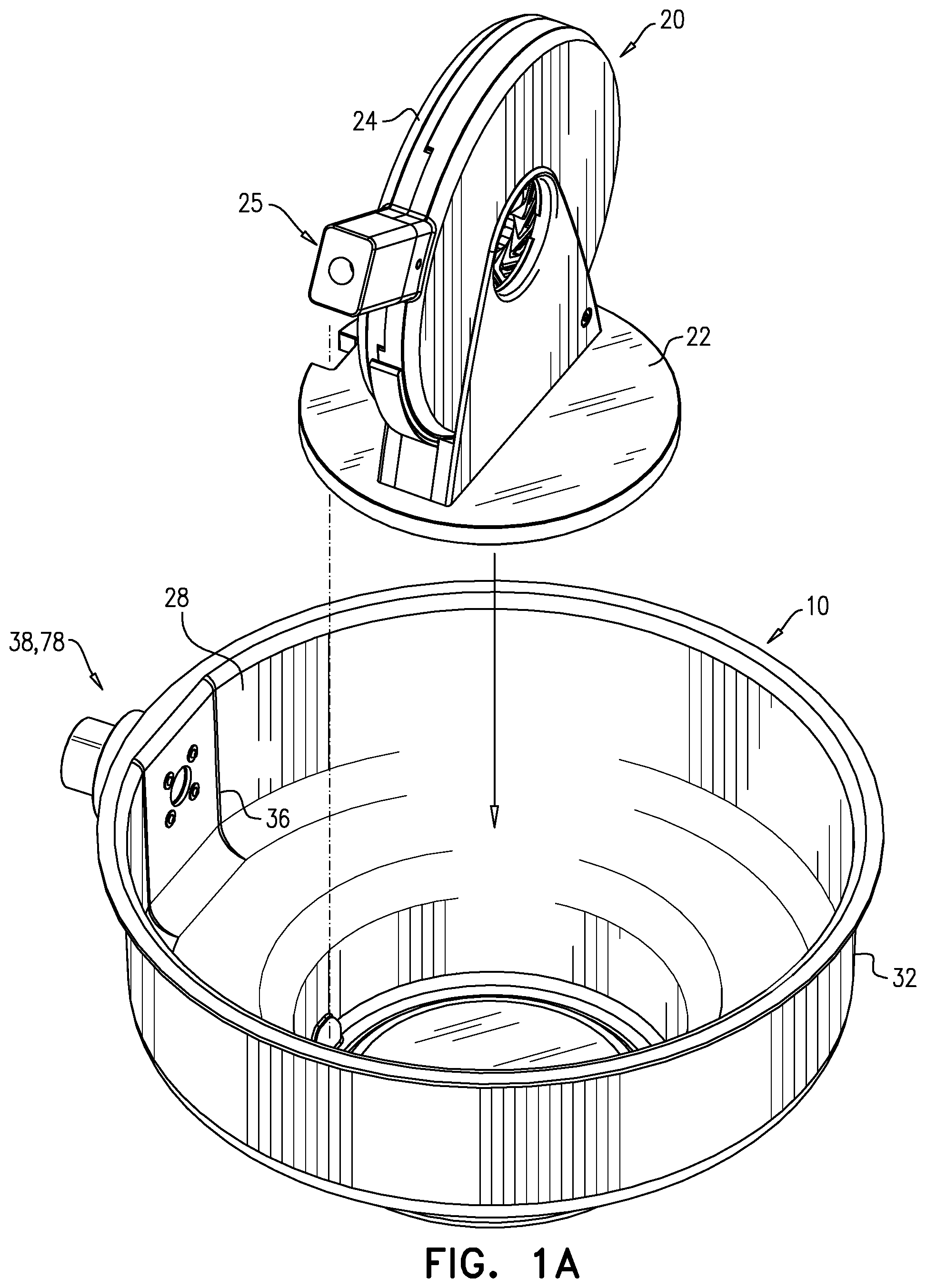
[0132] FIGS. 1A-C are schematic illustrations of a crimping assembly, comprising a crimping device and a bath, in accordance with some applications of the invention;
[0133] FIGS. 2A-E are schematic illustrations showing a crimping assembly being used in combination with a delivery tool to crimp a frame of an implant, in accordance with some applications of the invention;
[0134] FIG. 3 is a schematic illustration of a seal connected by a cap to an external portion of a port, in accordance with some applications of the invention;
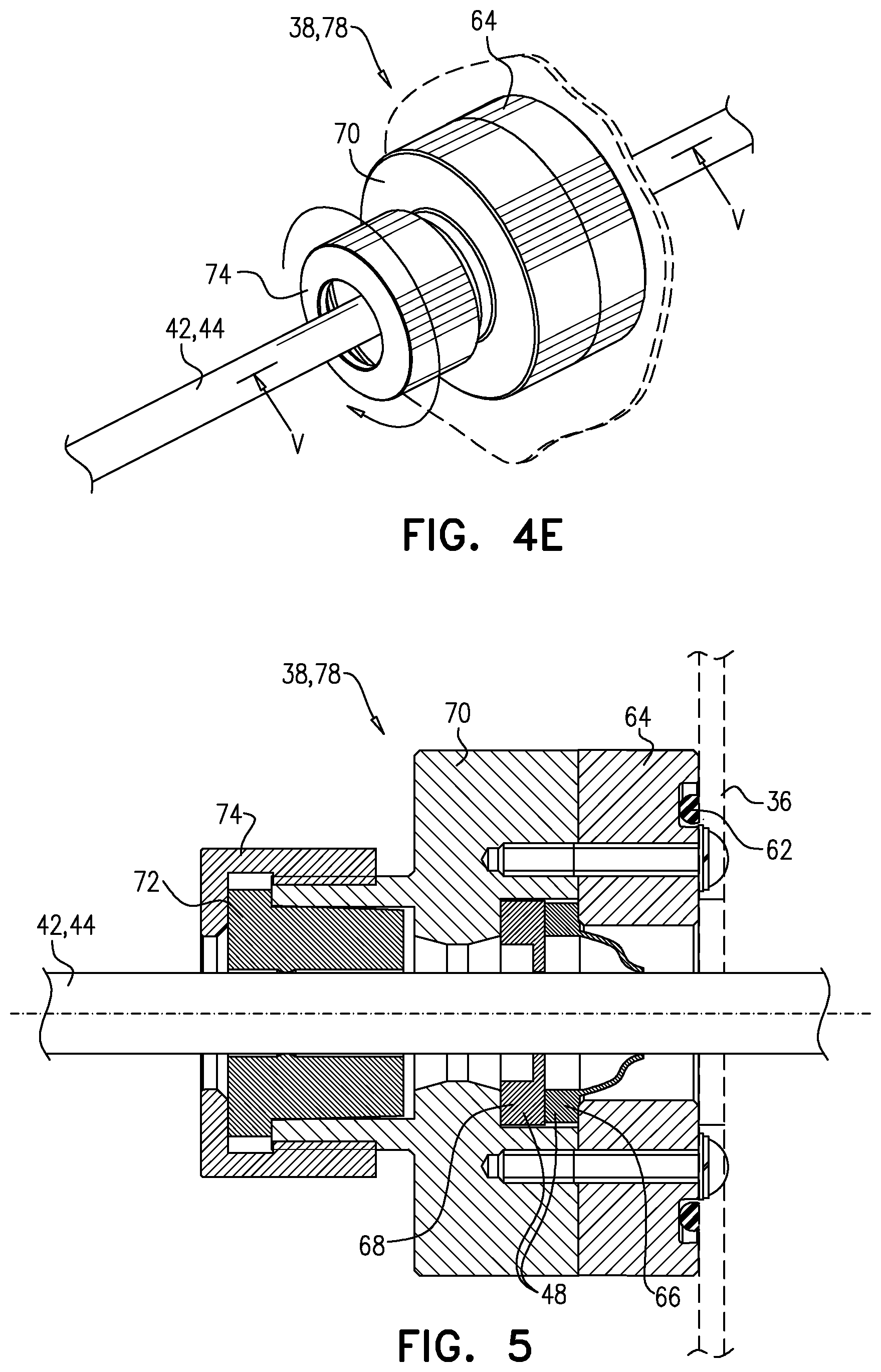
[0135] FIGS. 4A-E are schematic illustrations showing the use of a delivery tool with a cap, the port, and a plurality of plugs, in accordance with some applications of the invention;
[0136] FIG. 5 is a schematic illustration showing sealing of the port around a delivery tool shaft, in accordance with some applications of the invention; and
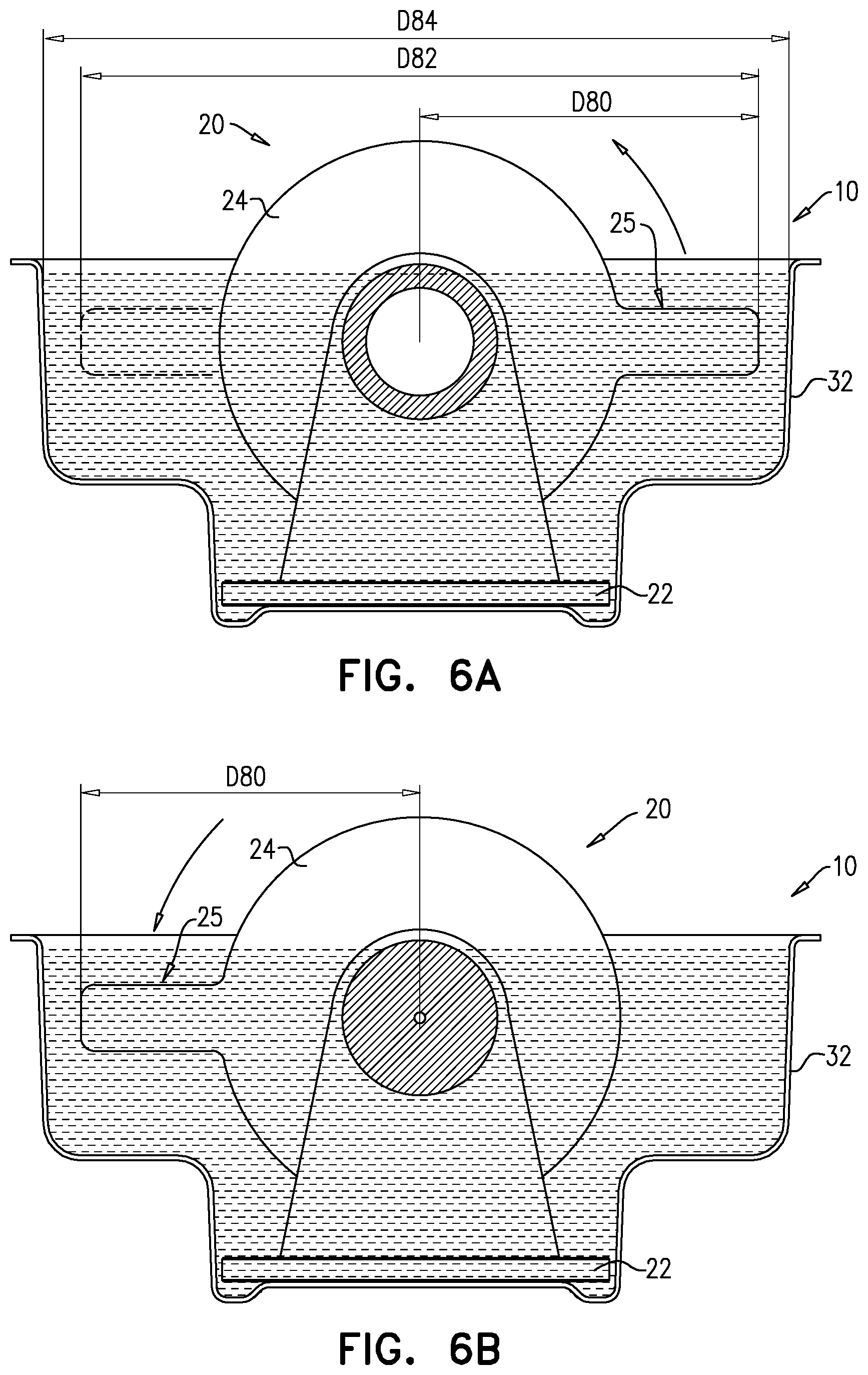
[0137] FIGS. 6A-B are schematic illustrations showing use of the crimping device disposed within the bath, in accordance with some applications of the invention.
DETAILED DESCRIPTION OF EMBODIMENTS
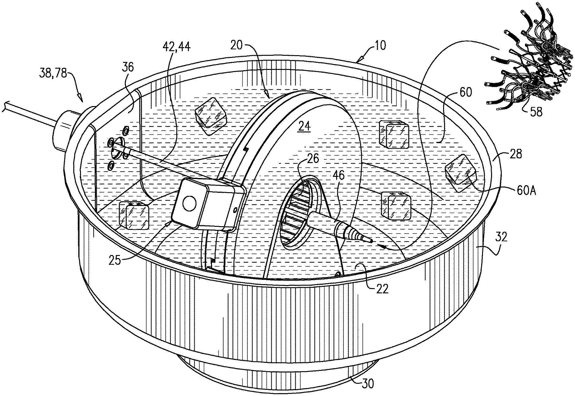
[0138] Reference is made to FIGS. 1A-C, which are schematic illustrations of a crimping assembly 10, comprising a crimping device 20 and a bath 28, in accordance with some applications of the invention.
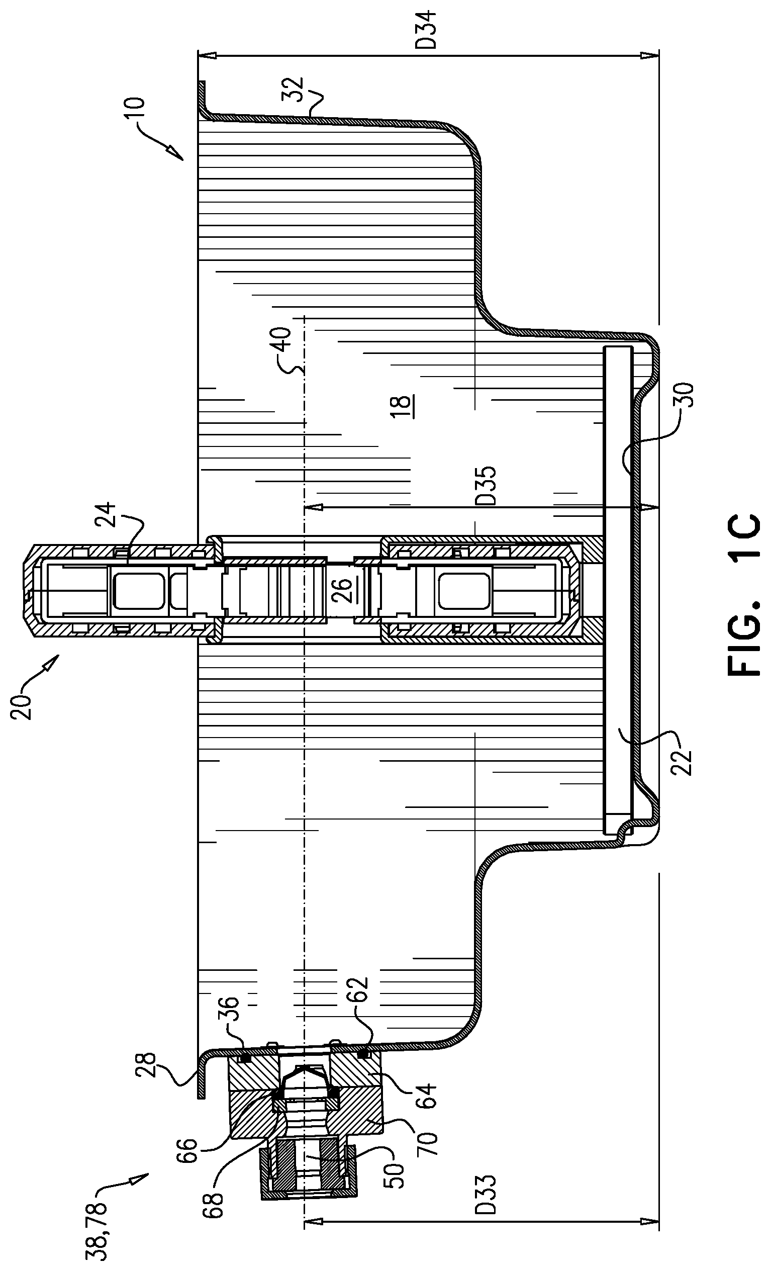
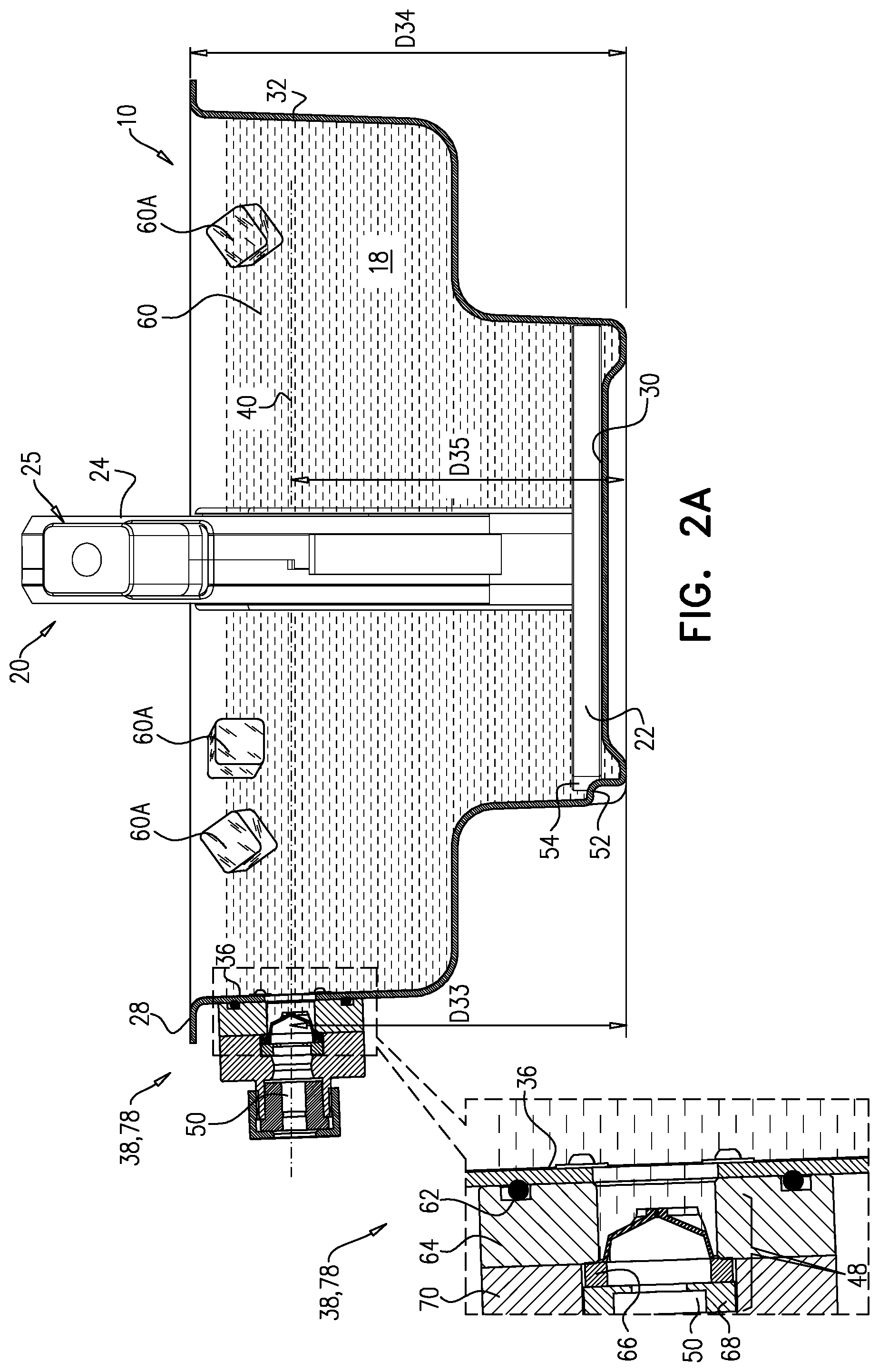
[0139] Crimping device 20 comprises a base 22, and a crimping mechanism 24 that defines a crimping aperture 26 having an open state shown in FIGS. 2B, 2C & 6A, as well as a narrowed state shown in FIGS. 2D and 6B. Bath 28 has a floor 30, and one or more side-walls 32 extending upward from the floor to a side-wall height D34. Typically, side-wall height D34 is the height to which bath 28 is fillable with a liquid, e.g., the lowest height of the one or more side-walls. Bath 28 defines a receptacle 18 that is shaped to receive a portion of crimping device 20, such that the crimping device is held securely by the bath 28.
[0140] FIGS. 1A-2E show crimping assembly 10 in its assembled state, in which crimping device 20 is disposed within bath 28, and is held securely by the bath. In the assembled state, the aperture 26 is below side-wall height D34. Typically, and as shown, the receptacle 18 is a recess in floor 30 of bath 28, and the recess is shaped to snugly receive base 22 of crimping device 20.
[0141] Typically, and as shown, bath 28 includes a port-defining side-wall 36, which defines a port 38 that defines a channel 50 between outside of the bath and inside of the bath. Typically, in the assembled state port 38 is aligned with crimping aperture 26. For example, a height D35 of the aperture may be within 1 cm of a height D33 of the port. Alternatively or additionally, port 38 may be disposed in a rotational position of the aperture that is within 5 degrees of a rotational position of the port 38. This alignment typically places channel 50 and aperture 26 along a co-linear axis 40 (FIG. 1A).
[0142] For some applications, crimping assembly 10 comprises two or more separable components, which undergo assembly prior to use. For example, bath 28 and crimping device 20 may be provided as separate components, which are assembled prior to use, e.g., by the operator or by a technician. For such applications, assembly 10 is typically assembled by introducing a portion of the crimping device (e.g., base 22) into receptacle 18 (FIG. 1A).
[0143] Typically, and as shown, bath 28 is shaped to receive crimping device 20 in a pre-defined rotational orientation of the crimping device with respect to the bath, and receptacle 18 and the portion of the crimping device (e.g., base 22) are cooperatively shaped to inhibit, in the assembled state, rotation of the crimping device 20 from the pre-defined rotational orientation. For example, and as shown, receptacle 18 may define a protrusion 52, and device 20 (e.g., base 22 thereof) may be shaped to define a notch 54 (or vice versa), the protrusion being disposed within the notch.
[0144] It is to be noted that the scope of the invention includes the use of other features to securely hold crimping device 20 within bath 28. For example, complementary couplings such as catches and/or locks may be used.
[0145] For other applications, crimping assembly 10 may be provided pre-assembled, with crimping device 20 already secured within bath 28. For some such applications, device 20 does not comprise a distinct base 22. Aside from these differences, the pre-assembled crimping assembly is typically as described hereinabove.
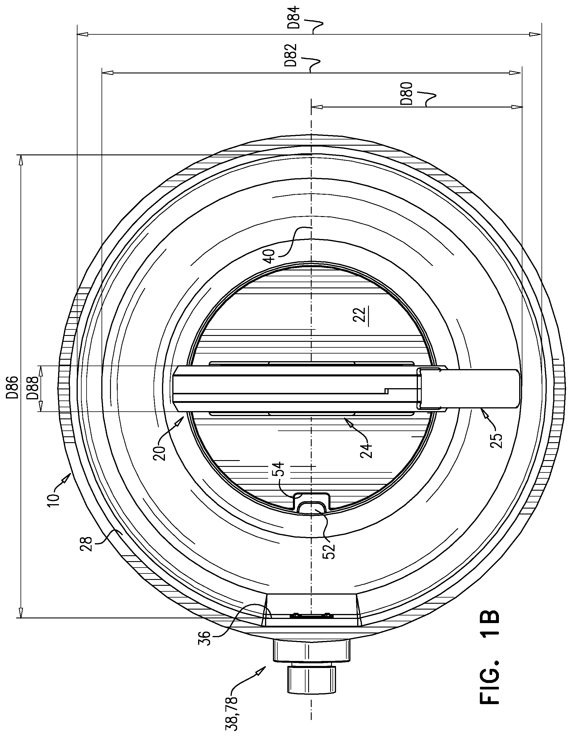
[0146] Reference is now also made to FIGS. 6A-B, which are schematic illustrations of crimping assembly 10, in accordance with some applications of the invention. Crimping mechanism 24 has a working radius D80 from the center of aperture 26 to the end of handle 25. For some applications, during the operation of crimping mechanism 24, handle 25 revolves about halfway circumferentially around mechanism 24 (i.e., with respect to aperture 26). Therefore, crimping mechanism 24 defines a working diameter D82, defined as twice working radius D80.
[0147] Bath 28 has an internal width D84, measured at height D33, typically transverse to axis 40. Typically, and as shown in FIG. 1B, internal width D84 is greater than working diameter D82. Typically, D84 is less than 10 cm greater than D82, (e.g., less than 5 cm greater, less than 2 cm greater, e.g., 1-10 mm greater).
[0148] Crimping mechanism 24 has a thickness D88. Thickness D88 is typically 2-5 cm (e.g., 2-3 cm). Typically, and as shown in FIG. 1B, bath 28 has another internal width D86, measured at height D33, measured along axis 40. For some applications, width D86 is sufficiently great that an operator may place a hand on each side of crimping mechanism 24 in order to load the implant onto the tool. Therefore, for some applications, width D86 is greater than thickness D88 plus 8-15 cm (e.g., 10-15 cm) on each side of crimping mechanism 24. Internal widths D84 and D88 are both typically 20-40 cm (e.g., 25-35 cm). For some applications, and as shown, bath 28 is generally circular, and diameters D84 and D88 are generally equal to each other (e.g., within 10 percent of each other, such as identical to each other).
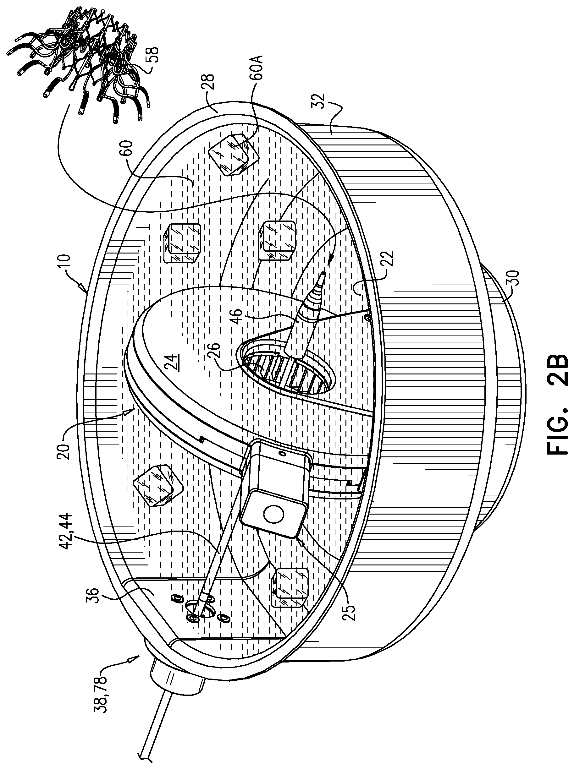
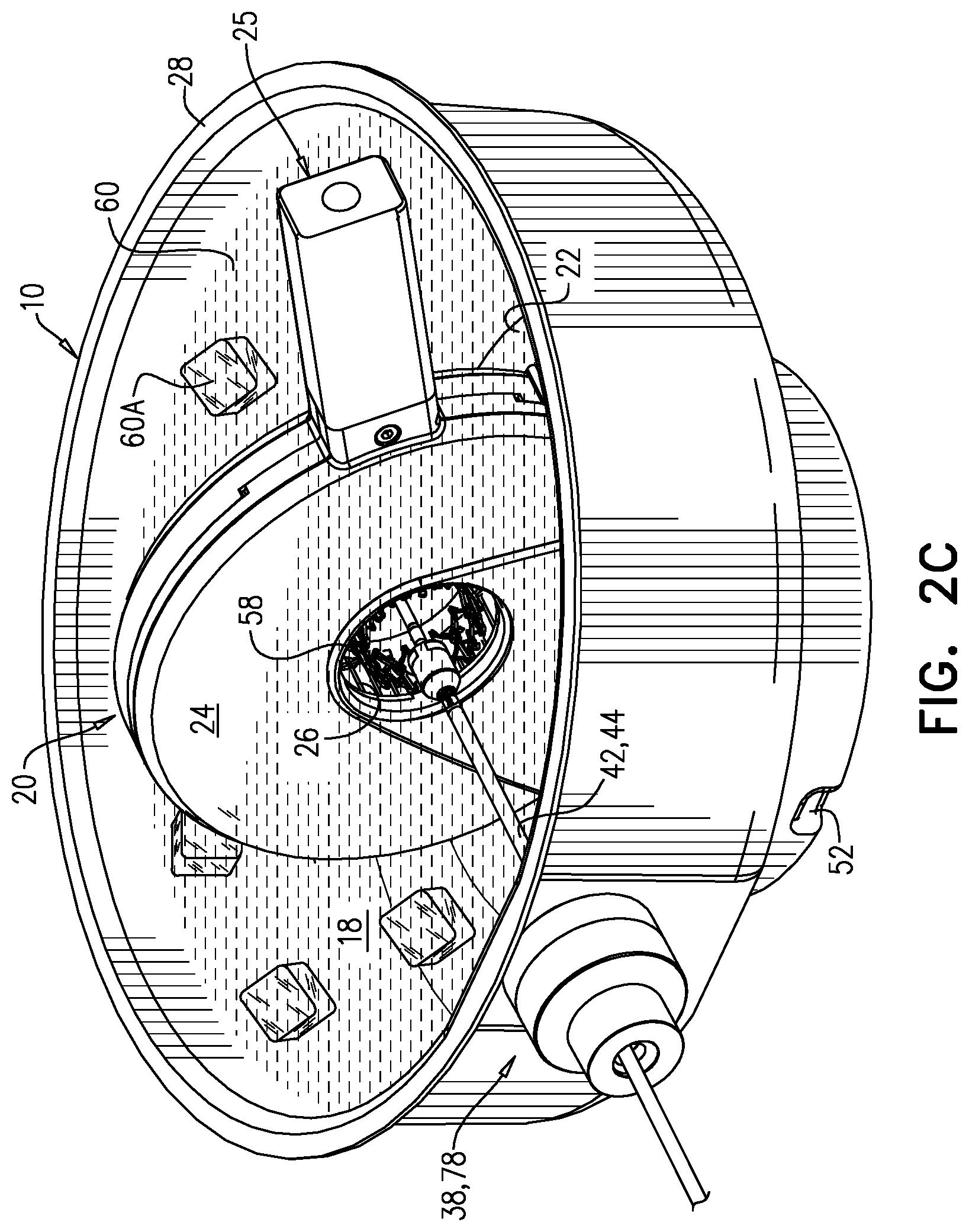
[0149] Reference is made to FIGS. 2A-E, which are schematic illustrations showing crimping assembly 10 being used in combination with a delivery tool 42 to crimp a frame 56 of an implant 58, in accordance with some applications of the invention. As shown, implant 58 (FIG. 2B) may comprise a prosthetic heart valve, to be implanted at a native heart valve of a subject. Frame 56 is typically a shape-memory alloy such as nickel titanium (Nitinol). When an SMA device, in its original shape and size, is cooled to its martensitic state, and subsequently deformed, it will retain its deformed shape and size. Upon warming of the SMA device to its austenitic state, the device will return to its original shape and size.
[0150] As depicted in FIG. 2A, the co-linear axis 40 of port 38 and crimping aperture 26 enables advancement of a delivery tool 42 (FIG. 2B), which as depicted may include a shaft 44 and housing 46, through port 38, at least until housing 46 reaches aperture 26. Port 38 typically comprises an external portion 78 that is outside the bath. In certain embodiments, port 38 defines channel 50 having an internal diameter of 6-15 mm (e.g., 6-10 mm or 10-15 mm), and comprises a seal 48 that reversibly closes the channel (detailed in FIG. 2E) configured to maintain sealing as housing 46 and shaft 44 pass through channel 50 during the advancing.
[0151] The presence of a cooled liquid 60 within bath 28 maintains frame 56 at a cool temperature during crimping of the frame. Liquid 60 typically has a temperature of between -2 and 12 degrees C. (e.g., 4-10 degrees C.). In some applications of the invention, a portion 61 of liquid 60 may be frozen. For example, as well as putting liquid 60 into bath 28, frozen liquid (e.g., saline ice) 60a may also be added, in order to maintain liquid 60 at its cool temperature throughout the duration of the crimping of frame 56.
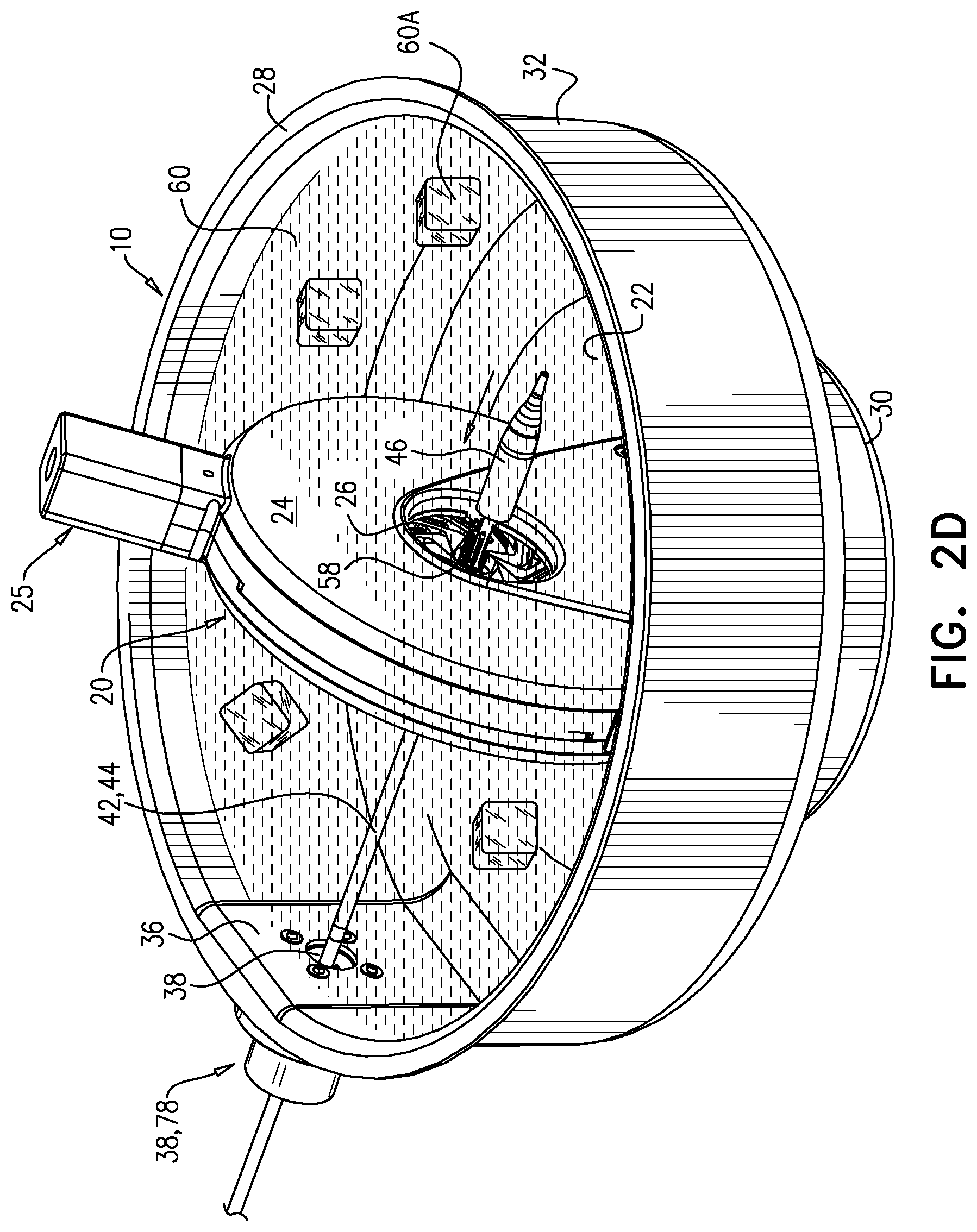
[0152] FIG. 2A shows assembly 10 prior to introduction of tool 42 or implant 58. FIG. 2A shows liquid 60 having been introduced into bath 28 prior to insertion of tool 42, but the liquid may alternatively be introduced after insertion of the tool. FIGS. 2B and 2C depict advancement of tool 42 into crimping aperture 26, such that frame 56 is disposed within the crimping aperture and immersed within cooled liquid 60. Frame 56 may be allowed to cool for a period of time while immersed in cooled liquid 60, prior to crimping. This period of time may typically last greater than 10 seconds (e.g., greater than 30 seconds) and/or less than 10 minutes (e.g., between 30 seconds and 10 minutes, such as 2-10 minutes). FIG. 2D shows contraction of crimping aperture 26 upon frame 56, crimping frame 56 while immersed in cooled liquid 60. Since implants comprising SMAs such as Nitinol are more easily deformed while in their martensitic state, it is therefore desirable to crimp such an implant while cooled below its transition temperature. Cooling of an SMA implant during crimping, which reduces a likelihood of damaging the implant or delivery tool during the crimping and loading processes, is achieved by disposition of crimping device 20 within a bath of the cooled liquid as shown in FIGS. 2C and 2D. FIG. 2E shows retraction of tool 42 through channel 50 of port 38, with implant 58 disposed within housing 46. Enlarged inset of FIG. 2E shows passage of tool shaft 44 through seal 48, while the seal prevents leakage of cooled liquid 60.
[0153] It is likely that some of liquid 60 becomes introduced into the subject during implantation of implant 58. Therefore, liquid 60 is typically suitable for introduction into the subject, e.g., being sterile, non-toxic, and/or isotonic. For example, liquid 60 may be sterile saline. It is to be noted that the crimping of implant 58 while immersed in cooled liquid 60, as described above, may reduce or obviate the need for subsequent flushing of air from the implant.
[0154] It is to be noted that the "heights" described herein (e.g., side-wall height D34, port-height D33, and aperture-height D35) are all heights above the same reference point, e.g., floor 30.
[0155] Reference is made to FIGS. 3, 4A-E, and 5, which are schematic illustrations showing the sealing of port 38 during advancing of housing 46 and shaft 44 of delivery tool 42 through the port. Some embodiments of the device include one or more washers 62, 66, and 68 fitted a first sealing nut 64 and a second sealing nut 70 (FIG. 3). Port 38 may be secured to port-defining side-wall 36 using screws (e.g., as shown), an adhesive, and/or any other suitable securing means.
[0156] Delivery tool housing 46 is advanced through a cap 74 (i.e., through an opening defined in the cap) (FIG. 4A). Subsequently, housing 46 is advanced through port 38 (FIG. 4B). Optionally, a plurality of plugs 72 are subsequently arranged into a ring that circumscribes shaft 44 and is disposed in an annular gap 76 between the shaft and external portion 78 of port 38 (FIGS. 4C-D).
[0157] Subsequently, cap 74 is fastened to external portion 78 of port 38 (FIG. 4E). For example, for some applications, an interior portion of cap 74 may be shaped to define threading, and cap 74 may be secured to port 38 by being screwed onto the port. Using cap 74 and plugs 72 in this manner allows port 38 to be configured to facilitate advancement of tool 42 through the port with relatively low resistance, and for sealing of the port 38 to be subsequently increased using the cap and plugs.
[0158] For some applications, the screwing of cap 74 onto external portion 78 pushes plugs 72 into gap 76.
[0159] It will be appreciated by persons skilled in the art that the present invention is not limited to what has been particularly shown and described hereinabove. Rather, the scope of the present invention includes both combinations and subcombinations of the various features described hereinabove, as well as variations and modifications thereof that are not in the prior art, which would occur to persons skilled in the art upon reading the foregoing description.
* * * * *
D00000
D00001
D00002
D00003
D00004
D00005
D00006
D00007
D00008
D00009
D00010
D00011
D00012
D00013
XML
uspto.report is an independent third-party trademark research tool that is not affiliated, endorsed, or sponsored by the United States Patent and Trademark Office (USPTO) or any other governmental organization. The information provided by uspto.report is based on publicly available data at the time of writing and is intended for informational purposes only.
While we strive to provide accurate and up-to-date information, we do not guarantee the accuracy, completeness, reliability, or suitability of the information displayed on this site. The use of this site is at your own risk. Any reliance you place on such information is therefore strictly at your own risk.
All official trademark data, including owner information, should be verified by visiting the official USPTO website at www.uspto.gov. This site is not intended to replace professional legal advice and should not be used as a substitute for consulting with a legal professional who is knowledgeable about trademark law.