Replacement Heart Valve With Improved Cusp Washout And Reduced Loading
Hayes; Michael G. ; et al.
U.S. patent application number 16/870266 was filed with the patent office on 2020-11-12 for replacement heart valve with improved cusp washout and reduced loading. This patent application is currently assigned to BOSTON SCIENTIFIC SCIMED, INC.. The applicant listed for this patent is BOSTON SCIENTIFIC SCIMED, INC.. Invention is credited to Michael G. Hayes, Tara Hogan.
| Application Number | 20200352708 16/870266 |
| Document ID | / |
| Family ID | 1000004845119 |
| Filed Date | 2020-11-12 |


View All Diagrams
| United States Patent Application | 20200352708 |
| Kind Code | A1 |
| Hayes; Michael G. ; et al. | November 12, 2020 |
REPLACEMENT HEART VALVE WITH IMPROVED CUSP WASHOUT AND REDUCED LOADING
Abstract
A medical implant may include an expandable anchor member having a lumen extending through the expandable anchor member from an inflow end to an outflow end; a plurality of valve leaflets disposed within the lumen extending through the expandable anchor member; a seal member disposed adjacent an exterior of the expandable anchor member; and a porous material extending from the seal member to the plurality of valve leaflets.
| Inventors: | Hayes; Michael G.; (Galway, IE) ; Hogan; Tara; (Galway, IE) | ||||||||||
| Applicant: |
|
||||||||||
|---|---|---|---|---|---|---|---|---|---|---|---|
| Assignee: | BOSTON SCIENTIFIC SCIMED,
INC. MAPLE GROVE MN |
||||||||||
| Family ID: | 1000004845119 | ||||||||||
| Appl. No.: | 16/870266 | ||||||||||
| Filed: | May 8, 2020 |
Related U.S. Patent Documents
| Application Number | Filing Date | Patent Number | ||
|---|---|---|---|---|
| 62846018 | May 10, 2019 | |||
| Current U.S. Class: | 1/1 |
| Current CPC Class: | A61F 2250/0069 20130101; A61F 2220/0008 20130101; A61F 2220/0075 20130101; A61F 2/2418 20130101 |
| International Class: | A61F 2/24 20060101 A61F002/24 |
Claims
1. A medical implant, comprising: an expandable anchor member having a lumen extending through the expandable anchor member from an inflow end to an outflow end; a plurality of valve leaflets disposed within the lumen extending through the expandable anchor member; a seal member disposed adjacent an exterior of the expandable anchor member; and a porous material extending from the seal member to the plurality of valve leaflets.
2. The medical implant of claim 16, wherein the seal member is disposed outside of the lumen extending through the expandable anchor member.
3. The medical implant of claim 16, wherein at least a portion of the porous material is disposed within the lumen extending through the expandable anchor member.
4. The medical implant of claim 16, wherein the seal member includes a reinforcing band disposed proximate the inflow end of the expandable anchor member.
5. The medical implant of claim 19, wherein the porous material extends from the reinforcing band to the plurality of valve leaflets.
6. The medical implant of claim 19, wherein the reinforcing band does not pass through interstices in the expandable anchor member.
7. The medical implant of claim 19, wherein the porous material does not pass through interstices in the expandable anchor member.
8. The medical implant of claim 16, wherein the porous material includes a polymeric coating.
9. A medical implant, comprising: an expandable anchor member having a lumen extending through the expandable anchor member from an inflow end to an outflow end; a plurality of valve leaflets disposed within the lumen extending through the expandable anchor member; a seal member disposed adjacent an exterior of the expandable anchor member; and a fabric material extending from the seal member to the plurality of valve leaflets, the fabric material having a plurality of holes therethrough permitting fluid to flow between an inflow side of the plurality of valve leaflets and an outflow side of the plurality of valve leaflets without passing through the plurality of valve leaflets.
10. The medical implant of claim 24, wherein at least one seal stitch secures the seal member to the fabric material.
11. The medical implant of claim 25, wherein the at least one seal stitch includes at least one whip stitch.
12. The medical implant of claim 24, wherein at least one leaflet stitch secures the fabric material to the plurality of valve leaflets.
13. The medical implant of claim 27, wherein the at least one leaflet stitch includes at least one whip stitch.
14. The medical implant of claim 27, wherein the at least one leaflet stitch includes a running stitch.
15. The medical implant of claim 27, wherein the at least one leaflet stitch includes a double running stitch.
16. A medical implant, comprising: an expandable anchor member having a lumen extending through the expandable anchor member from an inflow end to an outflow end; a plurality of valve leaflets disposed within the lumen extending through the expandable anchor member; and a seal member disposed adjacent an exterior of the expandable anchor member and attached to the plurality of valve leaflets at the inflow end of the expandable anchor member; wherein the plurality of valve leaflets each include a thinned region disposed proximate the inflow end of the expandable anchor member.
17. The medical implant of claim 31, wherein the thinned region includes a plurality of holes extending through the thinned region permitting fluid to flow between an inflow side of the plurality of valve leaflets and an outflow side of the plurality of valve leaflets without passing through a lumen defined by free edges of the plurality of leaflets.
18. The medical implant of claim 32, wherein the plurality of holes has a variable size.
19. The medical implant of claim 32, wherein the plurality of holes decreases in size in a direction from the inflow end of the expandable anchor member toward the outflow end of the expandable anchor member.
20. The medical implant of claim 31, wherein the thinned region does not pass through interstices in the expandable anchor member.
Description
CROSS-REFERENCE TO RELATED APPLICATIONS
[0001] This application claims the benefit of priority of U.S. Provisional Application No. 62/846,018 filed May 10, 2019, the entire disclosure of which is hereby incorporated by reference.
TECHNICAL FIELD
[0002] The present disclosure pertains to medical devices, and methods for manufacturing and/or using medical devices. More particularly, the present disclosure pertains to an improved design for a medical device and/or a replacement heart valve.
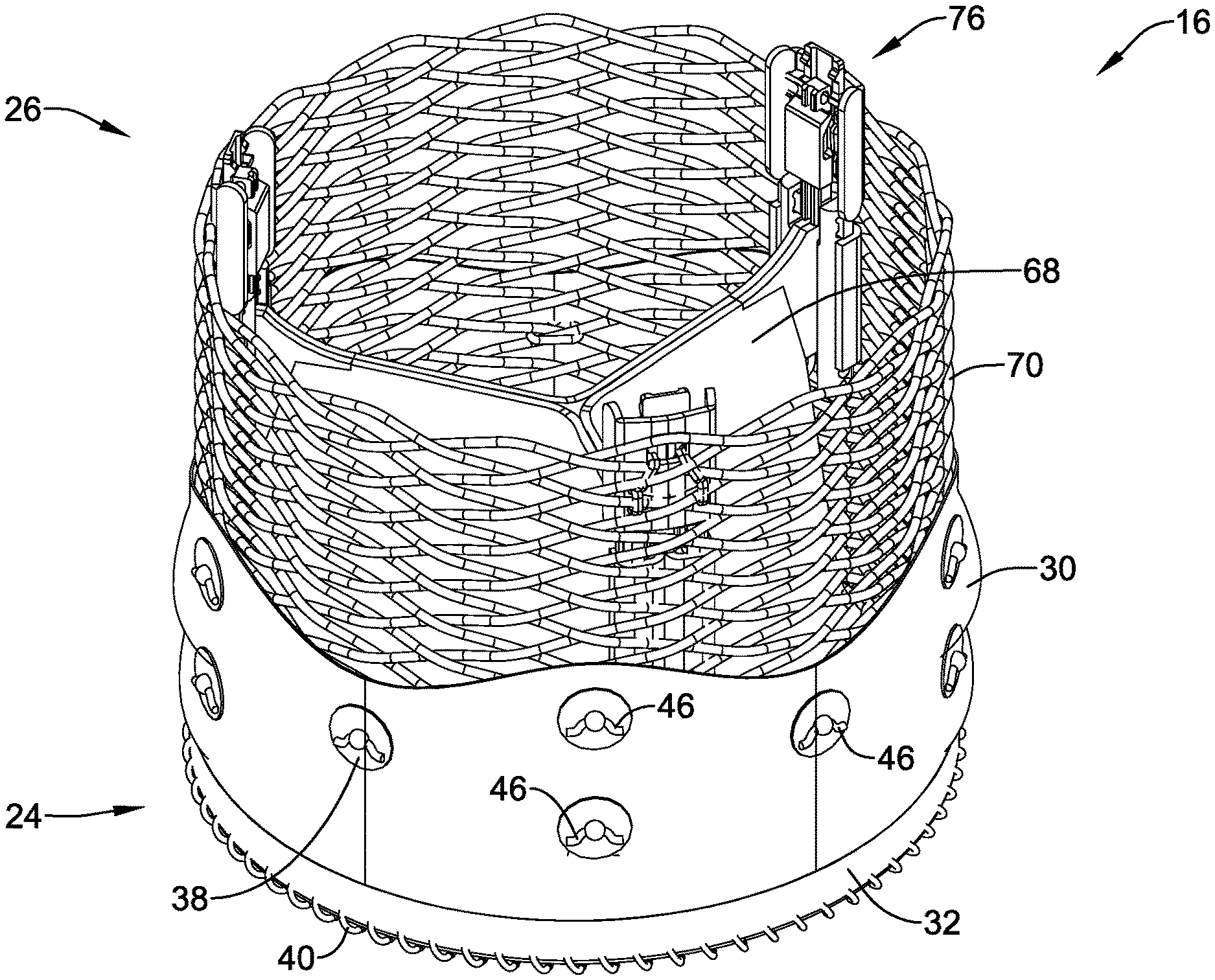
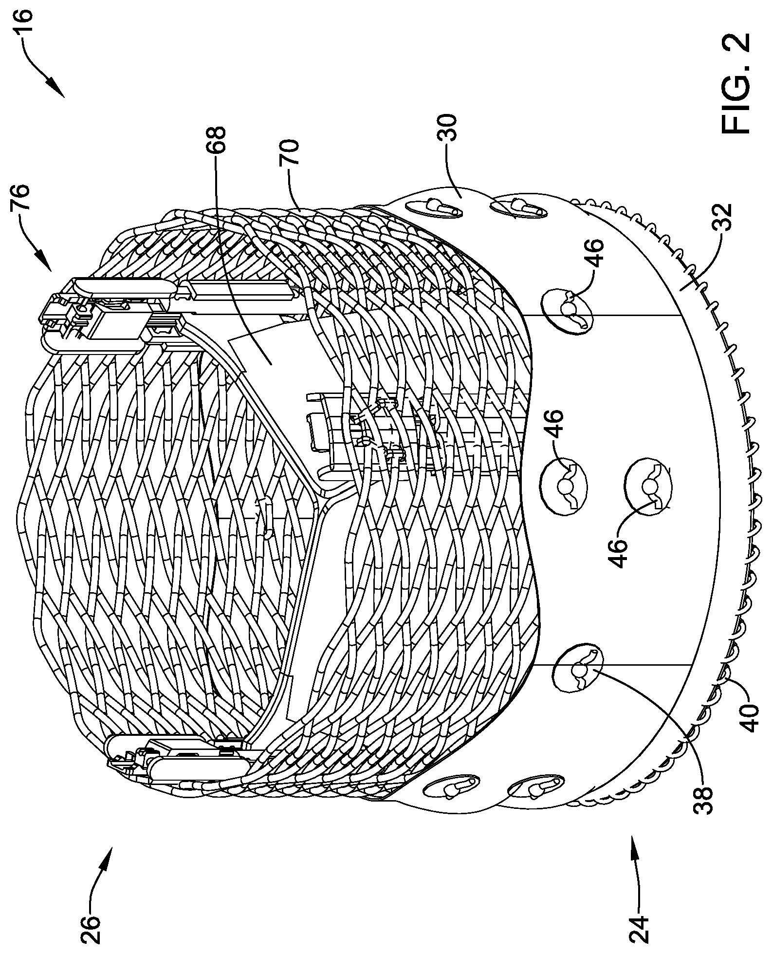
BACKGROUND
[0003] A wide variety of intracorporeal medical devices have been developed for medical use, for example, intravascular use. Some of these devices include guidewires, catheters, medical device delivery systems (e.g., for stents, grafts, replacement valves, etc.), and the like. These devices are manufactured by any one of a variety of different manufacturing methods and may be used according to any one of a variety of methods. Of the known medical devices and methods, each has certain advantages and disadvantages. There is an ongoing need to provide alternative medical devices as well as alternative methods for manufacturing and using medical devices.
SUMMARY
[0004] In a first aspect, a medical implant may comprise an expandable anchor member having a lumen extending through the expandable anchor member from an inflow end to an outflow end; a plurality of valve leaflets disposed within the lumen extending through the expandable anchor member; a seal member disposed adjacent an exterior of the expandable anchor member; and a porous material extending from the seal member to the plurality of valve leaflets.
[0005] In addition or alternatively, the seal member is disposed outside of the lumen extending through the expandable anchor member.
[0006] In addition or alternatively, at least a portion of the porous material is disposed within the lumen extending through the expandable anchor member.
[0007] In addition or alternatively, the seal member includes a reinforcing band disposed proximate the inflow end of the expandable anchor member.
[0008] In addition or alternatively, the porous material extends from the reinforcing band to the plurality of valve leaflets.
[0009] In addition or alternatively, the reinforcing band does not pass through interstices in the expandable anchor member.
[0010] In addition or alternatively, the porous material does not pass through interstices in the expandable anchor member.
[0011] In addition or alternatively, the porous material includes a polymeric coating.
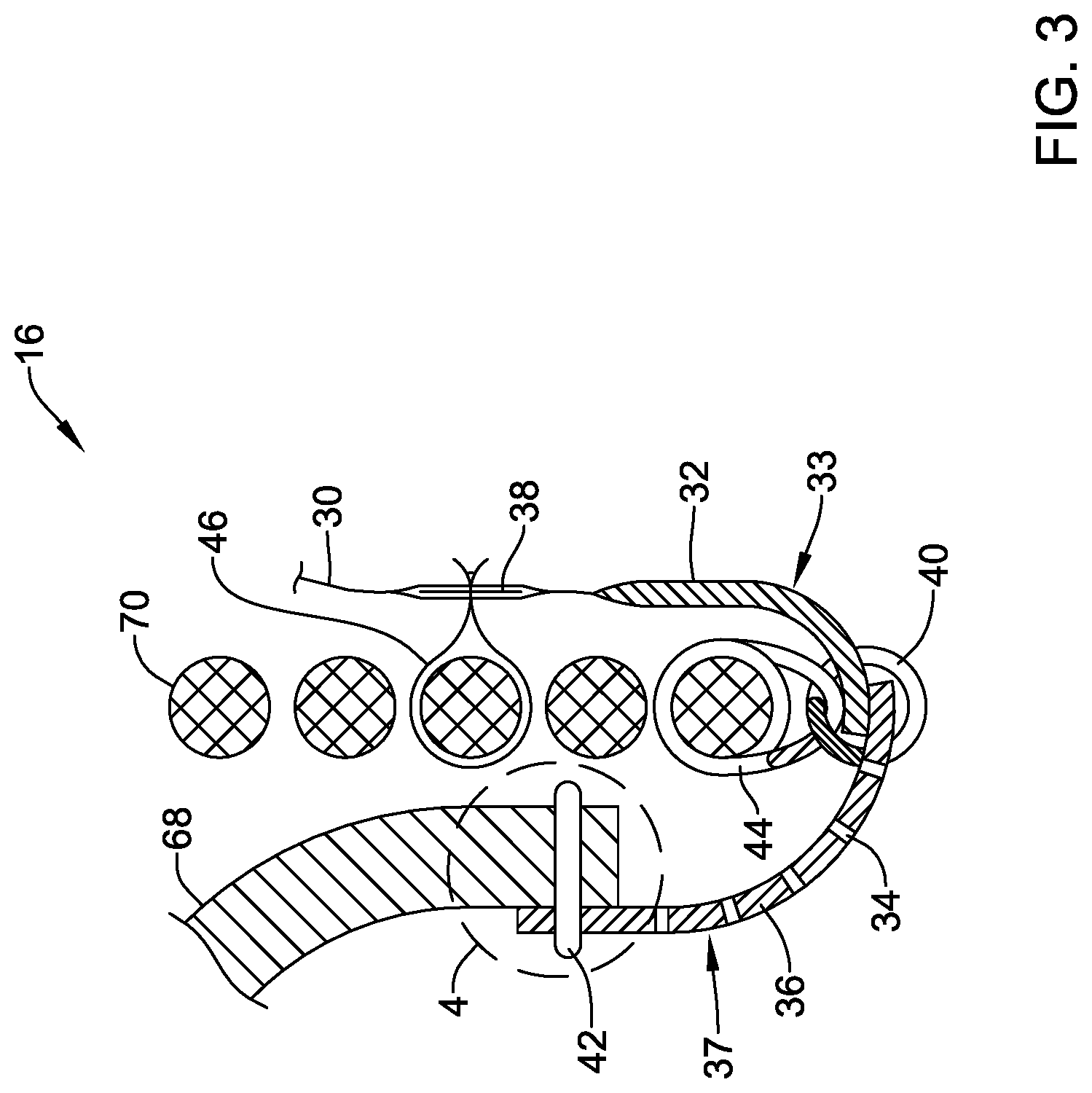
[0012] In addition or alternatively, a medical implant may comprise an expandable anchor member having a lumen extending through the expandable anchor member from an inflow end to an outflow end; a plurality of valve leaflets disposed within the lumen extending is through the expandable anchor member; a seal member disposed adjacent an exterior of the expandable anchor member; and a fabric material extending from the seal member to the plurality of valve leaflets, the fabric material having a plurality of holes therethrough permitting fluid to flow between an inflow side of the plurality of valve leaflets and an outflow side of the plurality of valve leaflets without passing through the plurality of valve leaflets.
[0013] In addition or alternatively, at least one seal stitch secures the seal member to the fabric material.
[0014] In addition or alternatively, the at least one seal stitch includes at least one whip stitch.
[0015] In addition or alternatively, at least one leaflet stitch secures the fabric material to the plurality of valve leaflets.
[0016] In addition or alternatively, the at least one leaflet stitch includes at least one whip stitch.
[0017] In addition or alternatively, the at least one leaflet stitch includes a running stitch.
[0018] In addition or alternatively, the at least one leaflet stitch includes a double running stitch.
[0019] In addition or alternatively, a medical implant may comprise an expandable anchor member having a lumen extending through the expandable anchor member from an inflow end to an outflow end; a plurality of valve leaflets disposed within the lumen extending through the expandable anchor member; and a seal member disposed adjacent an exterior of the expandable anchor member and attached to the plurality of valve leaflets at the inflow end of the expandable anchor member. The plurality of valve leaflets may each include a thinned region disposed proximate the inflow end of the expandable anchor member.
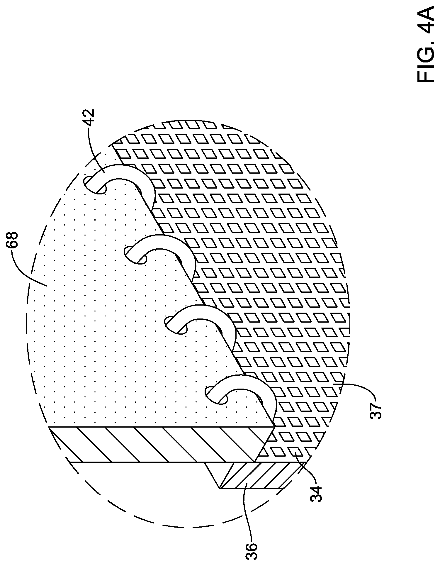
[0020] In addition or alternatively, the thinned region includes a plurality of holes extending through the thinned region permitting fluid to flow between an inflow side of the plurality of valve leaflets and an outflow side of the plurality of valve leaflets without passing through a lumen defined by free edges of the plurality of leaflets.
[0021] In addition or alternatively, the plurality of holes has a variable size.
[0022] In addition or alternatively, the plurality of holes decreases in size in a direction is from the inflow end of the expandable anchor member toward the outflow end of the expandable anchor member.
[0023] In addition or alternatively, the thinned region does not pass through interstices in the expandable anchor member.
[0024] The above summary of some embodiments, aspects, and/or examples is not intended to describe each disclosed embodiment or every implementation of the present disclosure. The Figures, and Detailed Description, which follow, more particularly exemplify these embodiments.
BRIEF DESCRIPTION OF THE DRAWINGS
[0025] The disclosure may be more completely understood in consideration of the following detailed description in connection with the accompanying drawings, in which:
[0026] FIG. 1 illustrates an example medical device system;
[0027] FIG. 2 illustrates an example medical implant associated with the example medical device system;
[0028] FIG. 3 is a partial section view illustrating aspects of the example medical implant;
[0029] FIG. 4A illustrates a partial perspective view of aspects of the example medical implant shown in FIG. 3;
[0030] FIG. 4B illustrates a partial perspective view of aspects of the example medical implant shown in FIG. 3;
[0031] FIG. 5 is a partial cutaway view illustrating aspects of the example medical implant;
[0032] FIG. 6 is a partial cutaway view illustrating aspects of the example medical implant;
[0033] FIG. 7 is a partial section view illustrating aspects of the example medical implant;
[0034] FIG. 8 is a partial section view illustrating aspects of the example medical implant; and
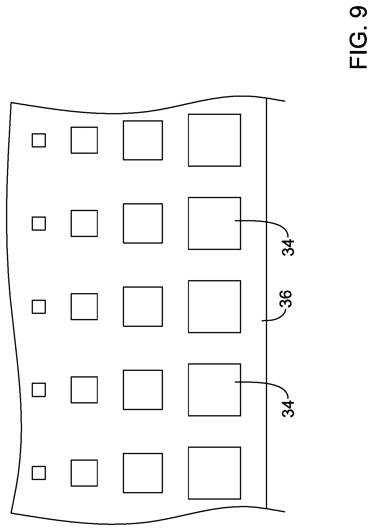
[0035] FIG. 9 illustrates selected aspects of the example medical implant.
[0036] While aspects of the disclosure are amenable to various modifications and alternative forms, specifics thereof have been shown by way of example in the drawings and will be described in detail. It should be understood, however, that the intention is not to limit aspects of the disclosure to the particular embodiments described. On the contrary, is the intention is to cover all modifications, equivalents, and alternatives falling within the spirit and scope of the disclosure.
DETAILED DESCRIPTION
[0037] The following description should be read with reference to the drawings, which are not necessarily to scale, wherein like reference numerals indicate like elements throughout the several views. The detailed description and drawings are intended to illustrate but not limit the claimed invention. Those skilled in the art will recognize that the various elements described and/or shown may be arranged in various combinations and configurations without departing from the scope of the disclosure. The detailed description and drawings illustrate example embodiments of the claimed invention.
[0038] For the following defined terms, these definitions shall be applied, unless a different definition is given in the claims or elsewhere in this specification.
[0039] All numeric values are herein assumed to be modified by the term "about," whether or not explicitly indicated. The term "about", in the context of numeric values, generally refers to a range of numbers that one of skill in the art would consider equivalent to the recited value (e.g., having the same function or result). In many instances, the term "about" may include numbers that are rounded to the nearest significant figure. Other uses of the term "about" (e.g., in a context other than numeric values) may be assumed to have their ordinary and customary definition(s), as understood from and consistent with the context of the specification, unless otherwise specified.
[0040] The recitation of numerical ranges by endpoints includes all numbers within that range, including the endpoints (e.g., 1 to 5 includes 1, 1.5, 2, 2.75, 3, 3.80, 4, and 5).
[0041] Although some suitable dimensions, ranges, and/or values pertaining to various components, features and/or specifications are disclosed, one of skill in the art, incited by the present disclosure, would understand desired dimensions, ranges, and/or values may deviate from those expressly disclosed.
[0042] As used in this specification and the appended claims, the singular forms "a", "an", and "the" include plural referents unless the content clearly dictates otherwise. As used in this specification and the appended claims, the term "or" is generally employed in its sense including "and/or" unless the content clearly dictates otherwise. It is to be noted that in order to facilitate understanding, certain features of the disclosure may be described in the singular, even though those features may be plural or recurring within the disclosed embodiment(s). Each instance of the features may include and/or be encompassed by the singular disclosure(s), unless expressly stated to the contrary. For simplicity and clarity purposes, not all elements of the disclosed invention are necessarily shown in each figure or discussed in detail below. However, it will be understood that the following discussion may apply equally to any and/or all of the components for which there are more than one, unless explicitly stated to the contrary. Additionally, not all instances of some elements or features may be shown in each figure for clarity.
[0043] Relative terms such as "proximal", "distal", "advance", "retract", variants thereof, and the like, may be generally considered with respect to the positioning, direction, and/or operation of various elements relative to a user/operator/manipulator of the device, wherein "proximal" and "retract" indicate or refer to closer to or toward the user and "distal" and "advance" indicate or refer to farther from or away from the user. In some instances, the terms "proximal" and "distal" may be arbitrarily assigned in an effort to facilitate understanding of the disclosure, and such instances will be readily apparent to the skilled artisan. Other relative terms, such as "upstream", "downstream", "inflow", and "outflow" refer to a direction of fluid flow within a lumen, such as a body lumen, a blood vessel, or within a device. Still other relative terms, such as "axial", "circumferential", "longitudinal", "lateral", "radial", etc. and/or variants thereof generally refer to direction and/or orientation relative to a central longitudinal axis of the disclosed structure or device.
[0044] The term "extent" may be understood to mean a greatest measurement of a stated or identified dimension, unless the extent or dimension in question is preceded by or identified as a "minimum", which may be understood to mean a smallest measurement of the stated or identified dimension. For example, "outer extent" may be understood to mean an outer dimension, "radial extent" may be understood to mean a radial dimension, "longitudinal extent" may be understood to mean a longitudinal dimension, etc. Each instance of an "extent" may be different (e.g., axial, longitudinal, lateral, radial, circumferential, etc.) and will be apparent to the skilled person from the context of the individual usage. Generally, an "extent" may be considered a greatest possible dimension measured according to the intended usage, while a "minimum extent" may be considered is a smallest possible dimension measured according to the intended usage. In some instances, an "extent" may generally be measured orthogonally within a plane and/or cross-section, but may be, as will be apparent from the particular context, measured differently--such as, but not limited to, angularly, radially, circumferentially (e.g., along an arc), etc.
[0045] The terms "monolithic" and "unitary" shall generally refer to an element or elements made from or consisting of a single structure or base unit/element. A monolithic and/or unitary element shall exclude structure and/or features made by assembling or otherwise joining multiple discrete structures or elements together.
[0046] It is noted that references in the specification to "an embodiment", "some embodiments", "other embodiments", etc., indicate that the embodiment(s) described may include a particular feature, structure, or characteristic, but every embodiment may not necessarily include the particular feature, structure, or characteristic. Moreover, such phrases are not necessarily referring to the same embodiment. Further, when a particular feature, structure, or characteristic is described in connection with an embodiment, it would be within the knowledge of one skilled in the art to effect the particular feature, structure, or characteristic in connection with other embodiments, whether or not explicitly described, unless clearly stated to the contrary. That is, the various individual elements described below, even if not explicitly shown in a particular combination, are nevertheless contemplated as being combinable or arrangeable with each other to form other additional embodiments or to complement and/or enrich the described embodiment(s), as would be understood by one of ordinary skill in the art.
[0047] For the purpose of clarity, certain identifying numerical nomenclature (e.g., first, second, third, fourth, etc.) may be used throughout the description and/or claims to name and/or differentiate between various described and/or claimed features. It is to be understood that the numerical nomenclature is not intended to be limiting and is exemplary only. In some embodiments, alterations of and deviations from previously-used numerical nomenclature may be made in the interest of brevity and clarity. That is, a feature identified as a "first" element may later be referred to as a "second" element, a "third" element, etc. or may be omitted entirely, and/or a different feature may be referred to as the "first" element. The meaning and/or designation in each instance will be apparent to the skilled practitioner.
[0048] Diseases and/or medical conditions that impact the cardiovascular system are prevalent throughout the world. Traditionally, treatment of the cardiovascular system was often conducted by directly accessing the impacted part of the system. For example, treatment of a blockage in one or more of the coronary arteries was traditionally treated using coronary artery bypass surgery. As can be readily appreciated, such therapies are rather invasive to the patient and require significant recovery times and/or treatments. More recently, less invasive therapies have been developed, for example, where a blocked coronary artery could be accessed and treated via a percutaneous catheter (e.g., angioplasty). Such therapies have gained wide acceptance among patients and clinicians.
[0049] Some relatively common medical conditions may include or be the result of inefficiency, ineffectiveness, or complete failure of one or more of the valves within the heart. For example, failure of the aortic valve or the mitral valve can have a serious effect on a human and could lead to a serious health condition and/or death if not dealt with properly. Treatment of defective heart valves poses other challenges in that the treatment often requires the repair or outright replacement of the defective heart valve. Such therapies may be highly invasive to the patient. Disclosed herein is a medical device system that may be used for delivering a medical implant to a portion of the cardiovascular system in order to diagnose, treat, and/or repair the system. At least some of the medical implants and/or systems disclosed herein may be used to deliver and implant a replacement heart valve implant (e.g., a replacement aortic valve, replacement mitral valve, etc.). In addition, the medical device system may deliver the replacement heart valve implant percutaneously and, thus, may be much less invasive to the patient. The device and/or system disclosed herein may also provide other desirable features and/or benefits as described below.
[0050] The figures illustrate selected components and/or arrangements of a medical device system 10. It should be noted that in any given figure, some features of the medical device system 10 may not be shown, or may be shown schematically, for simplicity. Additional details regarding some of the components of the medical device system 10 may be illustrated in other figures in greater detail. A medical device system 10 may be used to deliver and/or deploy a variety of medical devices to a number of locations within the anatomy. In at least some embodiments, the medical device system 10 may include a replacement heart valve delivery system (e.g., a replacement aortic valve delivery system) that can be used for percutaneous delivery of a replacement heart valve. This, however, is not intended to be limiting as the medical device system 10 may also be used for other interventions including mitral valve replacement, valve repair, valvuloplasty, and the like, or other similar interventions.
[0051] The medical device system 10, as seen in FIG. 1 for example, may generally be described as a catheter system that includes a delivery system having an outer sheath 12 for a medical implant 16 (i.e., a replacement heart valve implant, for example, which term may be used interchangeably with the term "medical implant" herein) which may be coupled to the delivery system and disposed within a lumen of the outer sheath 12 during delivery of the medical implant 16. In some embodiments, the delivery system may include an inner catheter 14 extending at least partially through the outer sheath 12 (partially seen in phantom in FIG. 1). In some embodiments, the medical implant 16 may be coupled to the inner catheter 14 and disposed within the lumen of the outer sheath 12 during delivery of the medical implant 16. In some embodiments, a handle 18 may be disposed and/or attached at a proximal end of the delivery system, as seen in FIG. 1, and may include one or more actuation means associated therewith. In some embodiments, the handle 18 may have an outer shell and an interior space. In some embodiments, the handle 18 may have a control knob rotatable relative to the outer shell of the handle 18. In some embodiments, the handle 18 and/or the control knob may be configured to manipulate the position of the outer sheath 12 relative to the inner catheter 14 and/or the medical implant 16, and/or to aid in the deployment of the medical implant 16. In some embodiments, the medical device system 10 may include a nose cone disposed at a distal end of a guidewire extension tube, wherein the guidewire extension tube may extend distally from the inner catheter 14. In at least some embodiments, the nose cone may be designed to have an atraumatic shape. In some embodiments, the nose cone may include a ridge or ledge that is configured to abut a distal tip of the outer sheath 12 during delivery of the medical implant 16. Some suitable but non-limiting materials for the medical device system 10, the outer sheath 12, the inner catheter 14, the handle 18, the control knob, and/or components or elements thereof, for example metallic materials and/or polymeric materials, are described below.
[0052] In use, the medical device system 10 may be advanced percutaneously through the is vasculature to a position adjacent to an area of interest or a target location. For example, the medical device system 10 may be advanced through the vasculature and across the aortic arch to a position adjacent to a defective aortic valve. Alternative approaches to treat a defective aortic valve and/or other heart valve(s) are also contemplated with the medical device system 10. During delivery, the medical implant 16 may be generally disposed in an elongated and low profile "delivery" configuration within the outer sheath 12 coupled to and/or distal of the inner catheter 14, as seen in FIG. 1, for example. Once positioned, the outer sheath 12 may be retracted relative to the inner catheter 14, which may be held stationary by the handle 18, and/or the medical implant 16 to expose the medical implant 16. The medical implant 16 may be actuated using the handle 18 and/or the control knob in order to translate the medical implant 16 into a generally expanded and larger profile "deployed" configuration (e.g., expanded as in FIG. 2, but still coupled to the inner catheter 14) suitable for implantation within the anatomy. When the medical implant 16 is suitably deployed within the anatomy, the medical implant 16 may be released and/or detached from the medical device system 10, the delivery system can be removed from the vasculature, leaving the medical implant 16 in place in a "released" configuration (e.g., FIG. 2) to function as, for example, a suitable replacement for the native aortic valve. In at least some interventions, the medical implant 16 may be deployed within the native valve (e.g., the native valve is left in place and not excised). Alternatively, the native valve may be removed (such as through valvuloplasty, for example) and the medical implant 16 may be deployed in its place as a replacement.
[0053] In at least some embodiments, the medical implant 16 may be disposed in an "everted" configuration or a partially-everted configuration while disposed within the lumen of the outer sheath 12 and/or immediately upon exposure after retracting the outer sheath 12. In some embodiments, the medical implant 16 may be everted in the "delivery" configuration. The "everted" configuration may involve at least a portion of the valve leaflets (discussed below) of the medical implant 16 being disposed outside of the expandable anchor member (discussed below) of the medical implant 16 during delivery, thereby permitting a smaller radial profile of the medical implant 16 and the use of a smaller overall profile of the outer sheath 12 and/or the medical device system 10. In some embodiments, the "delivery" configuration and the "everted" configuration may be is substantially similar and/or may be used interchangeably herein.
[0054] In some embodiments, the inner catheter 14 may be a tubular structure having one or more lumens extending therethrough. For example, in some embodiments, the inner catheter 14 may include one or more of a first lumen, a second lumen, a third lumen, and a fourth lumen. Other configurations are also contemplated. In some embodiments, the one or more lumens may extend along an entire length of the inner catheter 14. Other embodiments are contemplated, however, wherein one or more of the one or more lumens extend along only a portion of the length of the inner catheter 14. In some embodiments, a coupler assembly may be attached to the inner catheter 14 at and/or proximate a distal end of the inner catheter 14. In some embodiments, the coupler assembly may releasably couple the medical implant 16 to the inner catheter 14.
[0055] In some embodiments, the medical device system 10 may include at least one actuator element (not shown) releasably connecting the medical implant to the handle 18. For example, the at least one actuator element may extend from the handle 18 to the medical implant 16, the medical implant being disposed at a distal end of the lumen of the outer sheath 12. The at least one actuator element may extend distally from the inner catheter 14 to the medical implant 16. In some embodiments, the at least one actuator element may be slidably disposed within and/or may extend slidably through the inner catheter 14. For example, the at least one actuator element may be slidably disposed within one or more of the lumens of the inner catheter 14, and may be used to actuate (i.e., translate axially or longitudinally, and/or expand) the medical implant 16 between the "delivery" configuration, the "deployed" configuration, and/or the "released" configuration. In some embodiments, the at least one actuator element may include a plurality of actuator elements, two actuator elements, three actuator elements, four actuator elements, or another suitable or desired number of actuator elements.
[0056] For the purpose of discussion only, the medical device system 10 and/or the medical implant 16 of FIG. 2 may be configured to use three actuator elements (not shown). In use, a proximal end of each actuator element may be connected to the handle 18, and/or manipulated or otherwise actuated by a user using the handle 18 and/or the control knob, to reversibly shift the medical implant 16 from a "delivery" configuration to a "deployed" configuration, and to later shift the medical implant from the "deployed" configuration to a "released" configuration. During the release process for the medical implant 16, (e.g., as the medical implant 16 is actuated from the "delivery" configuration to the "deployed" configuration to the "released" configuration), the at least one actuator element may be retracted, withdrawn, and/or translated proximally relative to the inner catheter 14 and/or the medical implant 16. Some suitable but non-limiting materials for the actuator element, for example metallic materials or polymeric materials, are described below.
[0057] It is to be noted that in order to facilitate understanding, certain features of the disclosure may be described in the singular, even though those features may be plural or recurring within the disclosed embodiment(s). Each instance of the features may include and/or be encompassed by the singular disclosure(s), unless expressly stated to the contrary. For example, a reference to "the actuator element", "the leaflets", "the lumen", or other features may be equally referred to all instances and quantities beyond one of said feature. As such, it will be understood that the following discussion may apply equally to any and/or all of the components for which there are more than one within the medical implant 16 (i.e., the at least one actuator element, the plurality of leaflets, etc.) and/or the medical device system 10, unless explicitly stated to the contrary. Additionally, not all instances of some elements or features may be shown in each figure for clarity.
[0058] FIG. 2 illustrates some selected components of the medical implant 16. For example, here it can be seen that the medical implant 16 may include a plurality of valve leaflets 68 (e.g., bovine pericardial, polymeric, etc.) which may be secured to an expandable anchor member 70 that is reversibly actuatable between an elongated "delivery" configuration and an expanded "deployed" configuration. In some embodiments, the expandable anchor member 70 may form a tubular structure defining a central longitudinal axis and a lumen extending through the expandable anchor member 70 along, parallel to, coaxial with, and/or coincident with the central longitudinal axis from an inflow end 24 of the expandable anchor member 70 to an outflow end 26 of the expandable anchor member 70. In some embodiments, the expandable anchor member 70 may be and/or include an expandable stent having a plurality of struts. In some embodiments, the expandable anchor member 70 may be and/or include a braid formed from one or more filaments (e.g., a single filament, two filaments, etc.). The expandable anchor member 70 may include a plurality of interstices (e.g., openings) disposed in the is expandable anchor member 70. The plurality of interstices (e.g., openings) may pass from an interior or the expandable anchor member 70 to an exterior of the expandable anchor member 70 between adjacent struts and/or filaments. In some embodiments, the expandable anchor member 70 may be self-expanding. In some embodiments, the expandable anchor member 70 may be expanded via mechanical means, using a balloon, or other suitable methods of expansion. Other configurations are also contemplated. Some suitable but non-limiting materials for the expandable anchor member 70, for example metallic materials, polymeric materials, shape memory materials, etc., are described below.
[0059] In some embodiments, the medical implant 16 may include a plurality of locking elements 76 attached to the expandable anchor member 70, the plurality of locking elements 76 being configured to lock the expandable anchor member 70 in the "deployed" and/or "released" configuration(s). In some embodiments, the at least one actuator element may be configured to actuate the expandable anchor member 70 and/or the medical implant 16 between the "delivery" configuration and the "deployed" configuration and/or the "released" configuration.
[0060] In some embodiments, the plurality of locking elements 76 may each comprise an axially movable post member, for example at the commissure portions of the valve leaflets 68 (the post member may sometimes be referred to as a portion of a commissure post, which may serve to secure the valve leaflets 68, or the post member may be connected and/or attached to a commissure post), and a buckle member or other receiving element configured to slidably receive the post member therein to engage with the buckle member and thereafter lock the expandable anchor member 70 and/or the medical implant 16 in the "deployed" and/or the "released" configuration(s). In other words, in at least some embodiments, a medical implant 16 may include a plurality of post members and a corresponding plurality of buckle members. Other configurations and correspondences are also contemplated. Some suitable but non-limiting materials for the plurality of locking elements 76, the buckle member, and/or the post member, for example metallic materials or polymeric materials, are described below.
[0061] In some embodiments, the plurality of valve leaflets 68 may be secured to the expandable anchor member 70 at, adjacent to, and/or using (at least in part) corresponding post members. In some embodiments, the plurality of valve leaflets 68 may also be secured to the inflow end 24 of the expandable anchor member 70. In some embodiments, the plurality of valve leaflets 68 may be coupled and/or secured (i.e., to the post member, to the expandable anchor member 70, and/or back to themselves) using one or more sutures, threads, wires, filaments, adhesives, bonding agents, or other suitable elements and/or combinations thereof. In some embodiments, the plurality of valve leaflets 68 may be directly attached to the expandable anchor member 70. In some embodiments, the plurality of valve leaflets 68 may not be directly attached to the expandable anchor member 70.
[0062] In some embodiments, the post members and/or the commissure posts may be secured and/or attached to the expandable anchor member 70 (e.g., along the interior of the expandable anchor member) with sutures, tethers, adhesives, or other suitable elements. In some embodiments, the commissure post and/or the post member may include one or more holes or other features provided to aid in securing and/or attaching the commissure post and/or the post member to the expandable anchor member 70. Positioned adjacent to (e.g., aligned with) the plurality of post members is a corresponding plurality of buckle members, which may be secured and/or fixedly attached to the expandable anchor member 70 (e.g., along the interior of the expandable anchor member 70) with sutures, adhesives, or other suitable mechanisms. In some embodiments, the post member may be axially translatable relative to the buckle member generally parallel to the central longitudinal axis of the expandable anchor member 70 when the post member is at least partially disposed within and/or engaged with the buckle member.
[0063] In some embodiments, one buckle member may be fixedly attached to the expandable anchor member 70 adjacent to each of the post members. Accordingly, in some embodiments, the expandable anchor member 70 may have a total of three buckle members and three post members attached thereto. Similarly, one actuator element may be associated with each post member and buckle member, for a total of three actuator elements in the given example(s). Other embodiments are contemplated where fewer or more buckle members, post members, and/or actuator elements may be utilized.
[0064] In some embodiments, a seal member 30 may be circumferentially disposed on, about, and/or adjacent the exterior of the expandable anchor member 70, as seen in FIG. 2 for example, and as the term suggests, may help to seal the exterior of the medical implant 16 and/or the expandable anchor member 70 within and/or against a target site or area of interest upon deployment, thereby preventing leakage around the medical implant 16 and/or the expandable anchor member 70. The seal member 30 may be disposed outside of the lumen extending through the expandable anchor member 70. In some embodiments, the seal member 30 may be coupled and/or secured to the expandable anchor member 70 at one or more locations.
[0065] In some embodiments, the seal member 30 may include a plurality of grommets 38.
[0066] The plurality of grommets 38 may be attached to, bonded to, and/or at least partially embedded in the seal member 30. The plurality of grommets 38 may act as reinforcement points for attachment of the seal member 30 to the expandable anchor member 70 using a plurality of lashing sutures 46. In some embodiments, the plurality of lashing sutures 46 may extend through the plurality of grommets 38. In some embodiments, the plurality of lashing sutures 46 may attach the seal member 30 to the expandable anchor member 70 at non-consecutive intersections of the struts or filaments.
[0067] In some embodiments, the seal member 30 may include one or more layers of polymeric material. Some suitable polymeric materials may include, but are not necessarily limited to, polycarbonate, polyurethane, polyamide, polyether block amide, polyethylene, polyethylene terephthalate, polypropylene, polyvinylchloride, polytetrafluoroethylene, polysulfone, and copolymers, blends, mixtures or combinations thereof. Other suitable polymeric materials are also contemplated, some of which are discussed below.
[0068] In some embodiments, the modulus of elasticity may vary and/or be different from layer to layer. In other embodiments, the elongation to break may vary and/or be different from layer to layer. In some embodiments, the seal member 30 may also include a reinforcement, a reinforcing layer, and/or one or more reinforcing members added to the polymeric material prior to curing. The reinforcement, the reinforcing layer, and/or the one or more reinforcing members may comprise a woven or nonwoven fabric and may be positioned within or between the various layers. In some embodiments, the reinforcement, the reinforcing layer, and/or the one or more reinforcing members may be positioned on a radially innermost surface or radially outermost surface of the seal member 30. In some embodiments, the reinforcement, the reinforcing layer, and/or the one or more reinforcing members may be generally aligned. In some embodiments, the reinforcement, the reinforcing layer, and/or the one or more reinforcing members may be randomly oriented and/or disposed on the seal member 30. In some embodiments, at least a portion of the seal member 30 may be formed from a fabric material having a polymeric coating 33. In at least some embodiments, the seal member 30 may be impermeable to fluids and/or blood.
[0069] In some embodiments, the seal member 30 may include a reinforcing band 32 coupled to the seal member 30 and/or disposed proximate the inflow end 24 of the expandable anchor member 70. In some embodiments, the reinforcing band 32 may be integrally formed with, incorporated into, adhered to, and/or at least partially embedded within the seal member 30. In some embodiments, the reinforcing band 32 may be formed from a woven or nonwoven fabric material, a textile, or other thin flexible material. In some embodiments, the reinforcing band 32 may be the at least a portion of the seal member 30 formed from the fabric material having the polymeric coating 33. The reinforcing band 32 may provide tear resistance in the vicinity of sutures, filaments, or other attachment elements associated with components or aspects of the medical implant 16. In some embodiments, the reinforcing band 32 may have a longitudinal length measured parallel to the central longitudinal axis of about 1.5 millimeters, about 1.8 millimeters, about 2.0 millimeters, about 2.2 millimeters, about 2.5 millimeters, about 3 millimeters, etc.
[0070] In some embodiments, at least one seal stitch 40 may attach the inflow end of the seal member 30 and/or the reinforcing band 32 to the inflow end 24 of the expandable anchor member 70. In some embodiments, the at least one seal stitch 40 may include at least one whip stitch. A whip stitch may sometimes be referred to and/or interchanged with a helical stitch. In some embodiments, the at least one seal stitch 40 may form one or more first helical spirals oriented in a first direction about the inflow end 24 of the expandable anchor member 70.
[0071] In some embodiments, the medical implant 16 may include a porous material 36 extending from the seal member 30 and/or the reinforcing band 32 to the plurality of valve leaflets 68, as seen in FIG. 3 for example. In some embodiments, the porous material 36 may be a fabric material having a plurality of holes 34 therethrough permitting fluid (e.g., blood) to flow between an inflow side of the plurality of valve leaflets 68 and an outflow side of the plurality of valve leaflets 68 without passing through the plurality of valve leaflets 68 and/or without passing through a lumen defined by the free edges of the plurality of valve leaflets 68. For example, the porous material 36 may permit fluid (e.g., blood) to flow through the lumen extending through the expandable anchor member 70 from the inflow side of the plurality of valve leaflets 68 to the outflow side of the plurality of valve leaflets 68, from the outflow side of the plurality of valve leaflets 68 to the inflow side of the plurality of valve leaflets 68, or both, without passing through the plurality of valve leaflets 68 and/or without passing through a lumen defined by the free edges of the plurality of valve leaflets 68. In some embodiments, the porous material 36 may be a blood-permeable material. The blood-permeable material may include a fabric material. In some embodiments, the fabric material of the porous material 36 and/or the blood-permeable material may include a polymeric coating 37 disposed thereon. In some embodiments, the fabric material of the seal member 30 and/or the reinforcing band 32 is the fabric material of the porous material 36 and/or the blood-permeable material. For example, the same fabric material may extend continuously and/or uninterrupted through the seal member 30 and/or the reinforcing band 32 and the porous material 36. In some embodiments, the polymeric coating 33 of the seal member 30 and/or the reinforcing band 32 is the polymeric coating 37 of the porous material 36, the fabric material, and/or the blood-permeable material. For example, the same polymeric coating may be used for both polymeric coating 33 of the seal member 30 and/or the reinforcing band 32 and the polymeric coating 37 of the porous material 36, the fabric material, and/or the blood-permeable material. In some embodiments, the porous material 36 may be and/or may include a form of tissue, such as, but not limited to, bovine pericardial, porcine pericardial, or other suitable tissues (e.g., leaflet material, and the like).
[0072] At least a portion of the porous material 36, the blood-permeable material, and/or the fabric material is disposed within the lumen extending through the expandable anchor member 70. In some embodiments, the porous material 36, the fabric material, and/or the blood-permeable material may have about 30% open area, about 35% open area, about 38% open area, about 40% open area, about 45% open area, etc. In some embodiments, the porous material 36, the fabric material, and/or the blood-permeable material may have a longitudinal length measured parallel to the central longitudinal axis of about 3.0 millimeters, about 3.5 millimeters, about 3.8 millimeters, about 4.0 millimeters, about 4.2 millimeters, about 4.5 millimeters, about 5 millimeters, etc.
[0073] In some embodiments, the polymeric coating 33 of the seal member 30 and/or the reinforcing band 32 is thicker than the polymeric coating 37 of the porous material 36, the fabric material, and/or the blood-permeable material. For example, the polymeric coating 33 of the seal member 30 and/or the reinforcing band 32 may close, plug, and/or seal off any holes, apertures, pores, and/or openings extending therethrough, while the plurality of holes 34, apertures, pores, and/or openings extending through the porous material 36, the fabric material, and/or the blood-permeable material may be at least partially unobstructed by the polymeric coating 37 thereon. In some embodiments, the polymeric coating 33 of the seal member 30 and/or the reinforcing band 32 may be at least about 30 microns thick, about 40 microns thick, about 50 microns thick, about 55 microns thick, about 60 microns thick, or another suitable thickness. In some embodiments, the polymeric coating 37 of the porous material 36, the fabric material, and/or the blood-permeable material may be less than 10 microns thick, about 5 microns thick, about 3 microns thick, about 2 microns thick, about 1 micron thick, or another suitable thickness.
[0074] In some embodiments, the at least one seal stitch 40 may attach the reinforcing band 32 and/or the inflow end of the reinforcing band 32 to an inflow end of the porous material 36 (e.g., the fabric material, etc.) adjacent the inflow end 24 of the expandable anchor member 70. In some embodiments, one or more inflow lashing sutures 44 may secure the at least one seal stitch 40, the inflow end of the porous material 36, the inflow end of the seal member 30, and/or the reinforcing band 32 to the expandable anchor member 70 at, proximate, and/or to the inflow end 24 of the expandable anchor member 70. In at least some embodiments, the one or more inflow lashing sutures 44 may attach the at least one seal stitch 40, the inflow end of the porous material 36, the inflow end of the seal member 30, and/or the reinforcing band 32 to the strut(s), filament(s), and/or intersection(s) thereof of the expandable anchor member 70 disposed and/or positioned closest to the inflow end 24 of the expandable anchor member 70.
[0075] In some embodiments, the one or more inflow lashing sutures 44 may directly attach the at least one seal stitch 40 to the inflow end 24 of the expandable anchor member is 70. In some embodiments, the one or more inflow lashing sutures 44 may be interwoven with the at least one seal stitch 40 and/or a plurality of windings of the at least one seal stitch 40 to form a suture lattice. In some embodiments, at least a portion of the one or more inflow lashing sutures 44 may be looped through an interior of one or more of the plurality of windings of the at least one seal stitch 40 to form the suture lattice. In some embodiments, the one or more inflow lashing sutures 44 may form one or more second helical spirals oriented in a second direction about the inflow end 24 of the expandable anchor member 70. In some embodiments, the one or more inflow lashing sutures 44 may form one or more second helical spirals oriented in a second direction about the inflow end 24 of the expandable anchor member 70. In some embodiments, the first direction may be opposite the second direction.
[0076] As may be seen in FIG. 3, in at least some embodiments, the seal member 30 and/or the reinforcing band 32 does not pass through interstices in the expandable anchor member 70. In at least some embodiments, the porous material 36, the blood-permeable material, and/or the fabric material does not pass through interstices in the expandable anchor member 70. Instead, the seal member 30, the reinforcing band 32, the porous material 36, the blood-permeable material, and/or the fabric material may extend past and/or around the inflow end 24 of the expandable anchor member 70.
[0077] In some embodiments, at least one leaflet stitch 42 may secure the porous material 36, the blood-permeable material, and/or the fabric material to the plurality of valve leaflets 68. In some embodiments, the at least one leaflet stitch 42 may include at least one whip stitch, as shown in FIG. 4A. In some embodiments, the at least one leaflet stitch 42 may include a running stitch and/or a double running stitch, as shown in FIG. 4B. In some embodiments, the porous material 36, the blood-permeable material, and/or the fabric material may be further secured and/or attached to the plurality of valve leaflets 68 using an adhesive, a bonding agent, or other element(s).
[0078] In the partial cutaway view of FIG. 5, a portion of the expandable anchor member 70 and elements outside of the expandable anchor member 70 have been removed to view aspects of the medical implant 16 disposed within the expandable anchor member 70. In this configuration, the plurality of valve leaflets 68 may have a substantially straight inflow is end. Adjacent leaflets of the plurality of valve leaflets 68 may be secured and/or attached together at a valve commissure axially aligned with one of the plurality of locking elements 76 by a whip stitch 77, which may be a helical suture for example. The adjacent leaflets of the plurality of valve leaflets 68 may be attached to the post member of the locking element 76 by the whip stitch 77 or by one or more commissure sutures. As may be seen in FIG. 5, the porous material 36, the blood-permeable material, and/or the fabric material may extend inside of the plurality of valve leaflets 68 proximate the inflow end of the plurality of valve leaflets 68. In some embodiments, the porous material 36, the blood-permeable material, and/or the fabric material may have a substantially constant longitudinal length or profile, as shown in FIG. 5. In at least some embodiments, the porous material 36, the blood-permeable material, and/or the fabric material may extend from the inflow end 24 of the expandable anchor member 70 and/or from the seal member 30 and/or the reinforcing band 32 to the valve commissure. The porous material 36, the blood-permeable material, and/or the fabric material may be joined to the plurality of leaflets 68 by the at least one leaflet stitch 42, which may be a running stitch, a double running stitch, or a helical whip stitch, as described herein.
[0079] In some embodiments, the porous material 36, the blood-permeable material, and/or the fabric material may have a sinusoidal or wave-like longitudinal length and/or profile. In this configuration, the plurality of valve leaflets 68 may also have a sinusoidal or wave-like inflow end corresponding to the porous material 36, the blood-permeable material, and/or the fabric material.
[0080] In the partial cutaway view of FIG. 6, a portion of the expandable anchor member 70 and elements outside of the expandable anchor member 70 have been removed to view aspects of the medical implant 16 disposed within the expandable anchor member 70. In this configuration, the plurality of valve leaflets 68 may have a generally V-shaped inflow end corresponding to the porous material 36, the blood-permeable material, and/or the fabric material, wherein the plurality of valve leaflets 68 is shortest at and/or adjacent the valve commissures and is longest at a circumferential location equidistant between adjacent valve commissures. The porous material 36, the blood-permeable material, and/or the fabric material may have a generally V-shaped longitudinal length and/or profile, as shown is in FIG. 6. The porous material 36, the blood-permeable material, and/or the fabric material may be longest directly below and/or axially aligned with the plurality of locking elements 76 and/or the valve commissures. This area generally sees the least amount of movement of the plurality of leaflets 68 during use. The medical implant 16 illustrated herein, may have three areas of the V-shaped profile, one for each valve commissure. However, other configurations are also contemplated. In some embodiments, at least a portion of the plurality of holes 34 and/or the porous material 36, the blood-permeable material, and/or the fabric material may extend along and/or within at least 25%, at least 35%, at least 45%, at least 50%, at least 60%, or more of an axial length of the expandable anchor member 70 in the "deployed" configuration and/or the "released" configuration. Adjacent leaflets of the plurality of valve leaflets 68 may be secured and/or attached together at a valve commissure at one of the plurality of locking elements 76. The adjacent leaflets of the plurality of valve leaflets 68 may be attached to the post member of the locking element 76 by one or more commissure sutures. As may be seen in FIG. 6, the porous material 36, the blood-permeable material, and/or the fabric material may extend inside of the plurality of valve leaflets 68 proximate the inflow end of the plurality of valve leaflets 68. In at least some embodiments, the porous material 36, the blood-permeable material, and/or the fabric material may extend from the inflow end 24 of the expandable anchor member 70 and/or from the seal member 30 and/or the reinforcing band 32 to the valve commissure and/or the post member of the locking element 76. The porous material 36, the blood-permeable material, and/or the fabric material may be joined to the plurality of leaflets 68 by the at least one leaflet stitch 42, which may be a running stitch, a double running stitch, or a helical whip stitch, as described herein.
[0081] In an alternative configuration, the medical implant 16 may include a thinned region 69 of the plurality of valve leaflets 68 (e.g., leaflet tissue) extending to and/or attached directly to the seal member 30 and/or the reinforcing band 32, as seen in FIG. 7. In some embodiments, the thinned region 69 of the plurality of valve leaflets 68 may include a plurality of holes 67 extending therethrough, thereby functioning similarly to the porous material 36, the blood-permeable material, and/or the fabric material described above. The plurality of holes 67 may permit fluid (e.g., blood) to flow through the lumen extending through the expandable anchor member 70 from the inflow side of the plurality of valve leaflets 68 to the outflow side of the plurality of valve leaflets 68 without passing through a lumen defined by the free edges of the plurality of valve leaflets 68. For example, the plurality of holes 67 may permit fluid (e.g., blood) to flow through the lumen extending through the expandable anchor member 70 from the inflow side of the plurality of valve leaflets 68 to the outflow side of the plurality of valve leaflets 68, from the outflow side of the plurality of valve leaflets 68 to the inflow side of the plurality of valve leaflets 68, or both, without passing through the plurality of valve leaflets 68 and/or without passing through the lumen defined by the free edges of the plurality of valve leaflets 68.
[0082] In some embodiments, the thinned region 69 of the plurality of valve leaflets 68 may be formed by applying pressure to a portion of the plurality of valve leaflets 68 using a press or other means. In some embodiments, a portion of each of the plurality of valve leaflets 68 may be compressed to reduce a thickness of the portion of each of the plurality of valve leaflets 68 by about 30%, about 40%, about 50%, about 60%, about 70% or more. In some embodiments, the thinned region 69 may have a thickness that is approximately 1/3 of the thickness of an un-thinned region of the plurality of valve leaflets 68. In one example, the plurality of valve leaflets may have a thickness of about 0.381 millimeters (about 0.0015 inches) and the thinned region 69 may have a thickness of about 0.127 millimeters (about 0.005 inches). Other configurations and/or thicknesses are also contemplated.
[0083] At least a portion of the thinned region 69 including the plurality of holes 67 is disposed within the lumen extending through the expandable anchor member 70. In some embodiments, the thinned region 69 including the plurality of holes 67 may have about 30% open area, about 35% open area, about 38% open area, about 40% open area, about 45% open area, etc. In some embodiments, the thinned region 69 including the plurality of holes 67 may have a longitudinal length measured parallel to the central longitudinal axis of about 3.0 millimeters, about 3.5 millimeters, about 3.8 millimeters, about 4.0 millimeters, about 4.2 millimeters, about 4.5 millimeters, about 5 millimeters, etc.
[0084] In some embodiments, the at least one seal stitch 40 may attach the reinforcing band 32 and/or the inflow end of the reinforcing band 32 to an inflow end of the thinned region 69 including the plurality of holes 67 and/or the plurality of valve leaflets 68 adjacent the inflow end of the expandable anchor member 70. In some embodiments, one or more is inflow lashing sutures 44 may secure the at least one seal stitch 40, the inflow end of the thinned region 69 including the plurality of holes 67, the inflow end of the seal member 30, and/or the reinforcing band 32 to the expandable anchor member 70 at, proximate, and/or to the inflow end of the expandable anchor member 70. In at least some embodiments, the one or more inflow lashing sutures 44 may attach the at least one seal stitch 40, the inflow end of the thinned region 69 including the plurality of holes 67, the inflow end of the seal member 30, and/or the reinforcing band 32 to the strut(s), filament(s), and/or intersection(s) thereof of the expandable anchor member 70 disposed and/or positioned closest to the inflow end of the expandable anchor member 70.
[0085] In some embodiments, the one or more inflow lashing sutures 44 may directly attach the at least one seal stitch 40 to the inflow end of the expandable anchor member 70.
[0086] In some embodiments, the one or more inflow lashing sutures 44 may be interwoven with the at least one seal stitch 40 and/or a plurality of windings of the at least one seal stitch 40 to form a suture lattice. In some embodiments, at least a portion of the one or more inflow lashing sutures 44 may be looped through an interior of one or more of the plurality of windings of the at least one seal stitch 40 to form the suture lattice. In some embodiments, the one or more inflow lashing sutures 44 may form one or more second helical spirals oriented in a second direction about the inflow end of the expandable anchor member 70. In some embodiments, the one or more inflow lashing sutures 44 may form one or more second helical spirals oriented in a second direction about the inflow end of the expandable anchor member 70. In some embodiments, the first direction may be opposite the second direction.
[0087] As may be seen in FIG. 7, in at least some embodiments, the seal member 30 and/or the reinforcing band 32 does not pass through interstices in the expandable anchor member 70. In at least some embodiments, the thinned region 69 including the plurality of holes 67 does not pass through interstices in the expandable anchor member 70. Instead, the seal member 30, the reinforcing band 32, the thinned region 69 including the plurality of holes 67 may extend past and/or around the inflow end 24 of the expandable anchor member 70.
[0088] In another alternative configuration, the seal member 30 and/or the reinforcing band 32 may extend into the lumen of the expandable anchor member 70 and attach directly to the plurality of valve leaflets 68, as seen in FIG. 8. In some embodiments, the seal member is 30 and/or the reinforcing band 32 may include a plurality of holes 31 extending therethrough within the lumen of the expandable anchor member 70, thereby functioning similarly to the porous material 36, the blood-permeable material, and/or the fabric material described above. The plurality of holes 31 may permit fluid (e.g., blood) to flow through the lumen extending through the expandable anchor member 70 from the inflow side of the plurality of valve leaflets 68 to the outflow side of the plurality of valve leaflets 68 without passing through the plurality of valve leaflets 68 and/or a lumen defined by the free edges of the plurality of valve leaflets 68. For example, the plurality of holes 31 may permit fluid (e.g., blood) to flow through the lumen extending through the expandable anchor member 70 from the inflow side of the plurality of valve leaflets 68 to the outflow side of the plurality of valve leaflets 68, from the outflow side of the plurality of valve leaflets 68 to the inflow side of the plurality of valve leaflets 68, or both, without passing through the plurality of valve leaflets 68 and/or without passing through the lumen defined by the free edges of the plurality of valve leaflets 68.
[0089] At least a portion of the seal member 30 and/or the reinforcing band 32 including the plurality of holes 31 is disposed within the lumen extending through the expandable anchor member 70. In some embodiments, the seal member 30 and/or the reinforcing band 32 including the plurality of holes 31 may have about 30% open area, about 35% open area, about 38% open area, about 40% open area, about 45% open area, etc. In some embodiments, a portion of the seal member 30 and/or the reinforcing band 32 including the plurality of holes 31 may have a longitudinal length measured parallel to the central longitudinal axis of about 3.0 millimeters, about 3.5 millimeters, about 3.8 millimeters, about 4.0 millimeters, about 4.2 millimeters, about 4.5 millimeters, about 5 millimeters, etc.
[0090] In some embodiments, the polymeric coating 33 of the seal member 30 and/or the reinforcing band 32 outside of the lumen of the expandable anchor member 70 is thicker than the polymeric coating 37 disposed within the lumen of the expandable anchor member 70. For example, the polymeric coating 33 of the seal member 30 and/or the reinforcing band 32 may close, plug, and/or seal off any holes, apertures, pores, and/or openings extending therethrough outside of the lumen of the expandable anchor member 70, while the plurality of holes 31 extending through the seal member 30 and/or the reinforcing band is 32 within the lumen of the expandable anchor member 70 may be at least partially unobstructed by the polymeric coating 37 thereon. In some embodiments, the polymeric coating 33 of the seal member 30 and/or the reinforcing band 32 may be at least about 30 microns thick, about 40 microns thick, about 50 microns thick, about 55 microns thick, about 60 microns thick, or another suitable thickness. In some embodiments, the polymeric coating 37 may be less than 10 microns thick, about 5 microns thick, about 3 microns thick, about 2 microns thick, about 1 micron thick, or another suitable thickness. For example, the entire seal member 30 and/or the entire reinforcing band 32 may comprise a polymeric coating thereon. In some embodiments, the polymeric coating may have different and/or varying thicknesses depending on where the polymeric coating is disposed on the seal member 30 and/or the reinforcing band 32. As noted herein, it is desirable for the plurality of holes 31 to remain at least partially unobstructed to facilitate fluid passage therethrough. The plurality of holes 31 is disposed between the inflow end of the expandable anchor member 70 and the inflow end of the plurality of valve leaflets 68, within the lumen of the expandable anchor member 70. Similar to the configuration described above with respect to FIG. 3, at least one leaflet stitch 42 may secure the seal member 30 and/or the reinforcing band 32 to the plurality of valve leaflets 68 within the lumen of the expandable anchor member 70. In some embodiments, the at least one leaflet stitch 42 may include at least one whip stitch and/or at least one helical stitch (e.g., FIG. 4A). In some embodiments, the at least one leaflet stitch 42 may include a running stitch and/or a double running stitch (e.g., FIG. 4B). In at least some embodiments, an attachment region of the seal member 30 and/or the reinforcing band 32 to the plurality of valve leaflets 68 may have an increased thickness polymeric coating (e.g., polymeric coating 33) compared to the polymeric coating 37 disposed within the lumen of the expandable anchor member 70 to provide a more robust and/or durable attachment between the seal member 30 and/or the reinforcing band 32 and the plurality of valve leaflets 68. In some embodiments, the seal member 30 and/or the reinforcing band 32 may be further secured and/or attached to the plurality of valve leaflets 68 using an adhesive, bonding agent, or other element(s).
[0091] In some embodiments, the at least one seal stitch 40 may attach the seal member 30 and/or the reinforcing band 32 to the inflow end of the expandable anchor member 70 such is that the plurality of holes 31 is disposed within the lumen of the expandable anchor member 70. In some embodiments, the at least one seal stitch 40 may be at least one whip stitch or at least one helical stitch. In at least some embodiments, the at least one seal stitch 40 may attach the seal member 30 and/or the reinforcing band 32 to the strut(s), filament(s), and/or intersection(s) thereof of the expandable anchor member 70 disposed and/or positioned closest to the inflow end of the expandable anchor member 70.
[0092] As may be seen in FIG. 8, in at least some embodiments, the seal member 30 and/or the reinforcing band 32 does not pass through interstices in the expandable anchor member 70. In at least some embodiments, the seal member 30 and/or the reinforcing band 32 does not pass through interstices in the expandable anchor member 70. Instead, the seal member 30 and/or the reinforcing band 32 may extend past and/or around the inflow end of the expandable anchor member 70. Additionally, it is contemplated that the plurality of valve leaflets 68 and the seal member 30 and/or the reinforcing band 32 may have and/or take on any of the various arrangements illustrated in FIGS. 5-6, wherein the seal member 30 and/or the reinforcing band 32 may have a substantially constant longitudinal length, may have a sinusoidal or wave-like longitudinal length, and/or may have a generally V-shaped longitudinal length joined and/or attached directly to the plurality of valve leaflets 68 having a complimentary and/or corresponding length and/or shape.
[0093] FIG. 9 illustrates an alternative configuration for the plurality of holes 34 of the porous material 36, the blood-permeable material, and/or the fabric material discussed herein. In some embodiments, the plurality of holes 34 may have a variable size in a longitudinal direction. For example, the plurality of holes 34 may have a largest size proximate and/or adjacent the inflow end of the expandable anchor member 70, with the plurality of holes 34 gradually reducing in size in the longitudinal direction toward the plurality of valve leaflets 68 to a smallest size proximate and/or adjacent the inflow end of the plurality of valve leaflets 68. While expressly illustrated with respect to the plurality of holes 34, the same configuration may apply to the plurality of holes 67 of the thinned region 69 of the plurality of valve leaflets 68, as well as the plurality of holes 31 of the seal member 30 and/or the reinforcing band 32. Other configurations are also contemplated.
[0094] As a result of the aforementioned construction, the medical implant 16 may be is substantially sealed against fluid and/or blood flow around the exterior of the expandable anchor member 70 when positioned within the target site (e.g., the native valve) in the "deployed" configuration and/or the "released" configuration. The plurality of holes 34 of the porous material 36, the blood-permeable material, and/or the fabric material extending from the seal member 30 and/or the reinforcing band 32 to the plurality of valve leaflets 68, the plurality of holes 67 in the thinned region 69 of the plurality of valve leaflets 68, and/or the plurality of holes 31 in the seal member 30 and/or the reinforcing band 32 may provide one or more benefits to the function of the medical implant 16. For example, a pre-selected amount of fluid and/or blood may be permitted to flow through the plurality of holes 34, 67, 31. The pre-selected amount of fluid and/or blood may be selected to meet desired performance, anatomical, and/or regulatory requirements.
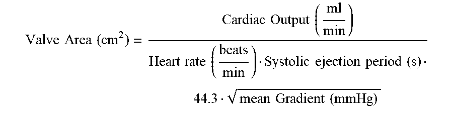
[0095] During the diastolic phase of the heartbeat, fluid and/or blood flow through the plurality of holes 34 of the porous material 36, the blood-permeable material, and/or the fabric material extending from the seal member 30 and/or the reinforcing band 32 to the plurality of valve leaflets 68, the plurality of holes 67 in the thinned region 69 of the plurality of valve leaflets 68, and/or the plurality of holes 31 in the seal member 30 and/or the reinforcing band 32 may serve to help "wash out" any fluid or blood that may be starting to stagnate behind the plurality of valve leaflets 68 in the cusps thereof (e.g., between the outflow side of the plurality of valve leaflets and the seal member 30 and/or the native valve annulus). This may help to prevent thrombus formation and/or release, which may have detrimental effects in/on other parts of the patient's anatomy. In some embodiments, the plurality of holes 34 of the porous material 36, the blood-permeable material, and/or the fabric material extending from the seal member 30 and/or the reinforcing band 32 to the plurality of valve leaflets 68, the plurality of holes 67 in the thinned region 69 of the plurality of valve leaflets 68, and/or the plurality of holes 31 in the seal member 30 and/or the reinforcing band 32 may alternatively and/or additionally reduce peak mechanical loads and/or strains applied to the expandable anchor member 70 during coaptation of the plurality of valve leaflets 68, thereby causing a damping effect during coaptation of the plurality of valve leaflets 68. Reducing peak mechanical loads and/or strains applied to the expandable anchor member 70, and/or the damping effect, may reduce wear and/or increase longevity of the expandable anchor member 70. is In another example, the plurality of holes 34 of the porous material 36, the blood-permeable material, and/or the fabric material extending from the seal member 30 and/or the reinforcing band 32 to the plurality of valve leaflets 68, the plurality of holes 67 in the thinned region 69 of the plurality of valve leaflets 68, and/or the plurality of holes 31 in the seal member 30 and/or the reinforcing band 32 may increase the effective orifice area (EOA) of the medical implant 16 by improving the flexibility and/or "hinge effect" of the plurality of valve leaflets 68 at the inflow end thereof when compared to medical implants lacking this feature and/or having valve leaflets secured directly to the expandable anchor member. The effective orifice area may be defined as the cross-sectional area through the lumen of the expandable anchor member 70 less the cross-sectional area through the lumen of the expandable anchor member 70 occupied by the plurality of valve leaflets 68 (e.g., the cross-sectional area through/within the plurality of leaflets 68 that is open to fluid flow during systole). The plurality of holes 34 of the porous material 36, the blood-permeable material, and/or the fabric material extending from the seal member 30 and/or the reinforcing band 32 to the plurality of valve leaflets 68, the plurality of holes 67 in the thinned region 69 of the plurality of valve leaflets 68, and/or the plurality of holes 31 in the seal member 30 and/or the reinforcing band 32 may permit the plurality of valve leaflets 68 to open faster and with less effort during systole, thereby reducing a pressure drop due to flow dynamics and/or minimizing the pressure gradient between inflow end and outflow end, which increases the effective orifice area when the Gorlin pressure equation is applied:
Valve Area ( cm 2 ) = Cardiac Output ( ml min ) Heart rate ( beats min ) Systolic ejection period ( s ) 44.3 mean Gradient ( mmHg ) ##EQU00001##
The Gorlin equation states that the aortic valve area is equal to the flow through the aortic valve during ventricular systole divided by the systolic pressure gradient across the valve times a constant.
[0096] The materials that can be used for the various components of the medical device system 10 (and/or other systems disclosed herein) and the various elements thereof disclosed herein may include those commonly associated with medical devices. For simplicity purposes, the following discussion refers to the medical device system 10 and/or the medical implant 16. However, this is not intended to limit the devices and methods described herein, as the discussion may be applied to other elements, members, components, or devices disclosed herein, such as, but not limited to, the seal member 30, the reinforcing band 32, the polymeric coating 33, the porous material 36, the polymeric coating 37, the grommets 38, the sutures 40/42/44/46/77, the expandable anchor member 70, and/or elements or components thereof.
[0097] In some embodiments, the medical device system 10, the delivery system, and/or the medical implant 16, and/or components thereof, may be made from a metal, metal alloy, polymer (some examples of which are disclosed below), a metal-polymer composite, ceramics, combinations thereof, and the like, or other suitable material.
[0098] Some examples of suitable polymers may include polytetrafluoroethylene (PTFE), ethylene tetrafluoroethylene (ETFE), fluorinated ethylene propylene (FEP), polyoxymethylene (POM, for example, DELRIN.RTM. available from DuPont), polyether block ester, polyurethane (for example, Polyurethane 85A), polypropylene (PP), polyvinylchloride (PVC), polyether-ester (for example, ARNITEL.RTM. available from DSM Engineering Plastics), ether or ester based copolymers (for example, butylene/poly(alkylene ether) phthalate and/or other polyester elastomers such as HYTREL.RTM. available from DuPont), polyamide (for example, DURETHAN.RTM. available from Bayer or CRISTAMID.RTM. available from Elf Atochem), elastomeric polyamides, block polyamide/ethers, polyether block amide (PEBA, for example available under the trade name PEBAX.RTM.), ethylene vinyl acetate copolymers (EVA), silicones, polyethylene (PE), Marlex high-density polyethylene, Marlex low-density polyethylene, linear low density polyethylene (for example REXELL.RTM.), polyester, polybutylene terephthalate (PBT), polyethylene terephthalate (PET), polytrimethylene terephthalate, polyethylene naphthalate (PEN), polyetheretherketone (PEEK), polyimide (PI), polyetherimide (PEI), polyphenylene sulfide (PPS), polyphenylene oxide (PPO), poly paraphenylene terephthalamide (for example, KEVLAR.RTM.), polysulfone, nylon, nylon-12 (such as GRILAMID.RTM. available from EMS American Grilon), perfluoro(propyl vinyl ether) (PFA), ethylene vinyl alcohol, polyolefin, polystyrene, epoxy, polyvinylidene chloride (PVdC), poly(styrene-b-isobutylene-b-styrene) (for example, SIBS and/or SIBS 50A), polycarbonates, polyurethane silicone copolymers (for example, ElastEon.RTM. from Aortech Biomaterials or ChronoSil.RTM. from AdvanSource Biomaterials), biocompatible polymers, other suitable materials, or mixtures, combinations, copolymers thereof, polymer/metal composites, and the like. In some embodiments the sheath can be blended with a liquid crystal polymer (LCP). For example, the mixture can contain up to about 6 percent LCP.
[0099] Some examples of suitable metals and metal alloys include stainless steel, such as 304V, 304L, and 316LV stainless steel; mild steel; nickel-titanium alloy such as linear-elastic and/or super-elastic nitinol; other nickel alloys such as nickel-chromium-molybdenum alloys (e.g., UNS: N06625 such as INCONEL.RTM. 625, UNS: N06022 such as HASTELLOY.RTM. C-22.RTM., UNS: N10276 such as HASTELLOY.RTM. C276.RTM., other HASTELLOY.RTM. alloys, and the like), nickel-copper alloys (e.g., UNS: N04400 such as MONEL.RTM. 400, NICKELVAC.RTM. 400, NICORROS.RTM. 400, and the like), nickel-cobalt-chromium-molybdenum alloys (e.g., UNS: R30035 such as MP35-N.RTM. and the like), nickel-molybdenum alloys (e.g., UNS: N10665 such as HASTELLOY.RTM. ALLOY B2.RTM.), other nickel-chromium alloys, other nickel-molybdenum alloys, other nickel-cobalt alloys, other nickel-iron alloys, other nickel-copper alloys, other nickel-tungsten or tungsten alloys, and the like; cobalt-chromium alloys; cobalt-chromium-molybdenum alloys (e.g., UNS: R30003 such as ELGILOY.RTM., PHYNOX.RTM., and the like); platinum enriched stainless steel; titanium; platinum; palladium; gold; combinations thereof; or any other suitable material.
[0100] As alluded to herein, within the family of commercially available nickel-titanium or nitinol alloys, is a category designated "linear elastic" or "non-super-elastic" which, although may be similar in chemistry to conventional shape memory and super elastic varieties, may exhibit distinct and useful mechanical properties. Linear elastic and/or non-super-elastic nitinol may be distinguished from super elastic nitinol in that the linear elastic and/or non-super-elastic nitinol does not display a substantial "superelastic plateau" or "flag region" in its stress/strain curve like super elastic nitinol does. Instead, in the linear elastic and/or non-super-elastic nitinol, as recoverable strain increases, the stress continues to increase in a substantially linear, or a somewhat, but not necessarily entirely linear relationship until plastic deformation begins or at least in a relationship that is more linear than the super elastic plateau and/or flag region that may be seen with super elastic nitinol. Thus, for the purposes of this disclosure linear elastic and/or non-super-elastic nitinol may also be termed "substantially" linear elastic and/or non-super-elastic nitinol.
[0101] In some cases, linear elastic and/or non-super-elastic nitinol may also be is distinguishable from super elastic nitinol in that linear elastic and/or non-super-elastic nitinol may accept up to about 2-5% strain while remaining substantially elastic (e.g., before plastically deforming) whereas super elastic nitinol may accept up to about 8% strain before plastically deforming. Both of these materials can be distinguished from other linear elastic materials such as stainless steel (that can also be distinguished based on its composition), which may accept only about 0.2 to 0.44 percent strain before plastically deforming.
[0102] In some embodiments, the linear elastic and/or non-super-elastic nickel-titanium alloy is an alloy that does not show any martensite/austenite phase changes that are detectable by differential scanning calorimetry (DSC) and dynamic metal thermal analysis (DMTA) analysis over a large temperature range. For example, in some embodiments, there may be no martensite/austenite phase changes detectable by DSC and DMTA analysis in the range of about -60 degrees Celsius (.degree. C.) to about 120.degree. C. in the linear elastic and/or non-super-elastic nickel-titanium alloy. The mechanical bending properties of such material may therefore be generally inert to the effect of temperature over this very broad range of temperature. In some embodiments, the mechanical bending properties of the linear elastic and/or non-super-elastic nickel-titanium alloy at ambient or room temperature are substantially the same as the mechanical properties at body temperature, for example, in that they do not display a super-elastic plateau and/or flag region. In other words, across a broad temperature range, the linear elastic and/or non-super-elastic nickel-titanium alloy maintains its linear elastic and/or non-super-elastic characteristics and/or properties. In some embodiments, the linear elastic and/or non-super-elastic nickel-titanium alloy may be in the range of about 50 to about 60 weight percent nickel, with the remainder being essentially titanium. In some embodiments, the composition is in the range of about 54 to about 57 weight percent nickel. One example of a suitable nickel-titanium alloy is FHP-NT alloy commercially available from Furukawa Techno Material Co. of Kanagawa, Japan. Other suitable materials may include ULTANIUM.TM. (available from Neo-Metrics) and GUM METAL.TM. (available from Toyota). In some other embodiments, a superelastic alloy, for example a superelastic nitinol can be used to achieve desired properties.
[0103] In at least some embodiments, portions or all of the delivery system and/or the medical implant 16, and/or components thereof, may also be doped with, made of, or otherwise include a radiopaque material. Radiopaque materials are understood to be materials capable of producing a relatively bright image on a fluoroscopy screen or another imaging technique during a medical procedure. This relatively bright image aids the user of the medical device system 10 in determining its location. Some examples of radiopaque materials can include, but are not limited to, gold, platinum, palladium, tantalum, tungsten alloy, polymer material loaded with a radiopaque filler, and the like. Additionally, other radiopaque marker bands and/or coils may also be incorporated into the design of the medical device system 10 to achieve the same result.
[0104] In some embodiments, a degree of Magnetic Resonance Imaging (MRI) compatibility is imparted into the medical device system 10 and/or the medical implant 16 and/or other elements disclosed herein. For example, the medical device system 10 and/or the medical implant 16, and/or components or portions thereof, may be made of a material that does not substantially distort the image and create substantial artifacts (i.e., gaps in the image). Certain ferromagnetic materials, for example, may not be suitable because they may create artifacts in an MRI image. The medical device system 10 and/or the medical implant 16, or portions thereof, may also be made from a material that the MRI machine can image. Some materials that exhibit these characteristics include, for example, tungsten, cobalt-chromium-molybdenum alloys (e.g., UNS: R30003 such as ELGILOY.RTM., PHYNOX.RTM., and the like), nickel-cobalt-chromium-molybdenum alloys (e.g., UNS: R30035 such as MP35-N.RTM. and the like), nitinol, and the like, and others.
[0105] In some embodiments, the medical device system 10 and/or the medical implant 16 and/or other elements disclosed herein may include a fabric material disposed over or within the structure. The fabric material may be composed of a biocompatible material, such a polymeric material or biomaterial, adapted to promote tissue ingrowth. In some embodiments, the fabric material may include a bioabsorbable material. Some examples of suitable fabric materials include, but are not limited to, polyethylene glycol (PEG), nylon, polytetrafluoroethylene (PTFE, ePTFE), a polyolefinic material such as a polyethylene, a polypropylene, polyester, polyurethane, and/or blends or combinations thereof.
[0106] In some embodiments, the medical device system 10 and/or the medical implant 16 and/or other elements disclosed herein may include and/or be formed from a textile material. Some examples of suitable textile materials may include synthetic yarns that may be flat, shaped, twisted, textured, pre-shrunk or un-shrunk. Synthetic biocompatible yarns suitable for use in the present invention include, but are not limited to, polyesters, including polyethylene terephthalate (PET) polyesters, polypropylenes, polyethylenes, polyurethanes, polyolefins, polyvinyl s, polymethylacetates, polyamides, naphthalene dicarboxylene derivatives, natural silk, and polytetrafluoroethylenes. Moreover, at least one of the synthetic yarns may be a metallic yarn or a glass or ceramic yarn or fiber. Useful metallic yarns include those yarns made from or containing stainless steel, platinum, gold, titanium, tantalum or a Ni--Co--Cr-based alloy. The yarns may further include carbon, glass or ceramic fibers. Desirably, the yarns are made from thermoplastic materials including, but not limited to, polyesters, polypropylenes, polyethylenes, polyurethanes, polynaphthalenes, polytetrafluoroethylenes, and the like. The yarns may be of the multifilament, monofilament, or spun-types. The type and denier of the yarn chosen may be selected in a manner which forms a biocompatible and implantable prosthesis and, more particularly, a vascular structure having desirable properties.
[0107] In some embodiments, the medical device system 10 and/or the medical implant 16 and/or other elements disclosed herein may include and/or be treated with a suitable therapeutic agent. Some examples of suitable therapeutic agents may include anti-thrombogenic agents (such as heparin, heparin derivatives, urokinase, and PPack (dextrophenylalanine proline arginine chloromethylketone)); anti-proliferative agents (such as enoxaparin, angiopeptin, monoclonal antibodies capable of blocking smooth muscle cell proliferation, hirudin, and acetylsalicylic acid); anti-inflammatory agents (such as dexamethasone, prednisolone, corticosterone, budesonide, estrogen, sulfasalazine, and mesalamine); antineoplastic/antiproliferative/anti-mitotic agents (such as paclitaxel, 5-fluorouracil, cisplatin, vinblastine, vincristine, epothilones, endostatin, angiostatin and thymidine kinase inhibitors); anesthetic agents (such as lidocaine, bupivacaine, and ropivacaine); anti-coagulants (such as D-Phe-Pro-Arg chloromethyl keton, an RGD peptide-containing compound, heparin, anti-thrombin compounds, platelet receptor antagonists, anti-thrombin antibodies, anti-platelet receptor antibodies, aspirin, prostaglandin inhibitors, platelet inhibitors, and tick antiplatelet peptides); vascular cell growth promoters (such as growth factor inhibitors, growth factor receptor antagonists, transcriptional activators, and translational promoters); vascular cell growth inhibitors (such as growth factor inhibitors, growth factor receptor antagonists, transcriptional repressors, translational repressors, replication inhibitors, inhibitory antibodies, antibodies directed against growth factors, bifunctional molecules consisting of a growth factor and a cytotoxin, bifunctional molecules consisting of an antibody and a cytotoxin); cholesterol-lowering agents; vasodilating agents; and agents which interfere with endogenous vasoactive mechanisms.
[0108] It should be understood that this disclosure is, in many respects, only illustrative. Changes may be made in details, particularly in matters of shape, size, and arrangement of steps without exceeding the scope of the invention. This may include, to the extent that it is appropriate, the use of any of the features of one example embodiment being used in other embodiments. The invention's scope is, of course, defined in the language in which the appended claims are expressed.
* * * * *
D00000
D00001
D00002
D00003
D00004
D00005
D00006
D00007
D00008
D00009
D00010
XML
uspto.report is an independent third-party trademark research tool that is not affiliated, endorsed, or sponsored by the United States Patent and Trademark Office (USPTO) or any other governmental organization. The information provided by uspto.report is based on publicly available data at the time of writing and is intended for informational purposes only.
While we strive to provide accurate and up-to-date information, we do not guarantee the accuracy, completeness, reliability, or suitability of the information displayed on this site. The use of this site is at your own risk. Any reliance you place on such information is therefore strictly at your own risk.
All official trademark data, including owner information, should be verified by visiting the official USPTO website at www.uspto.gov. This site is not intended to replace professional legal advice and should not be used as a substitute for consulting with a legal professional who is knowledgeable about trademark law.