Ligation Clip Cartridge
Thomas; Justin ; et al.
U.S. patent application number 16/830417 was filed with the patent office on 2020-11-12 for ligation clip cartridge. The applicant listed for this patent is Covidien LP. Invention is credited to Jacob C. Baril, Eric Brown, Matthew A. Dinino, Gregory R. Morck, Roy J. Pilletere, Justin Thomas.
| Application Number | 20200352575 16/830417 |
| Document ID | / |
| Family ID | 1000004746324 |
| Filed Date | 2020-11-12 |


| United States Patent Application | 20200352575 |
| Kind Code | A1 |
| Thomas; Justin ; et al. | November 12, 2020 |
LIGATION CLIP CARTRIDGE
Abstract
A ligation clip cartridge includes a housing and one or more retaining members. The housing defines a plurality of clip recesses that receive ligation clips. The retaining members are positioned on the housing to engage the clips within the housing in an unbiased state to minimize damage to the clip material caused by strain on the clip.
| Inventors: | Thomas; Justin; (New Haven, CT) ; Pilletere; Roy J.; (North Haven, CT) ; Dinino; Matthew A.; (Newington, CT) ; Morck; Gregory R.; (Haddam, CT) ; Brown; Eric; (Madison, CT) ; Baril; Jacob C.; (Norwalk, CT) | ||||||||||
| Applicant: |
|
||||||||||
|---|---|---|---|---|---|---|---|---|---|---|---|
| Family ID: | 1000004746324 | ||||||||||
| Appl. No.: | 16/830417 | ||||||||||
| Filed: | March 26, 2020 |
Related U.S. Patent Documents
| Application Number | Filing Date | Patent Number | ||
|---|---|---|---|---|
| 62844911 | May 8, 2019 | |||
| Current U.S. Class: | 1/1 |
| Current CPC Class: | A61B 17/122 20130101; A61B 2017/00862 20130101; A61B 17/1222 20130101; A61B 2017/00955 20130101; A61B 2017/00902 20130101 |
| International Class: | A61B 17/122 20060101 A61B017/122 |
Claims
1. A clip cartridge comprising; a housing including a body having side walls defining a central cavity and a plurality of dividing walls extending across the central cavity, each of the plurality of dividing walls defining a transverse axis and forming a clip recess within the central cavity with an adjacent one of the plurality of dividing walls, and a support member positioned within each of the clip recesses, the support member including a first support surface and a second support surface; a plurality of clips supported within the central cavity of the housing, one of the plurality of clips being supported within each of the clip recesses on the support member, each of the plurality of clips having a first and a second leg that are interconnected by a hinge portion; and at least one retainer supported on the housing, the at least one retainer having tabs that extend in a direction transverse to the transverse axis defined by the dividing walls, the tabs being positioned to engage the first and second legs of the plurality of clips to urge the first leg onto the first support surface of a respective support member and to urge the second leg onto the second support surface of a respective support member.
2. The clip cartridge of claim 1, wherein each of the first and second support surfaces of the support member is linear.
3. The clip cartridge of claim 1, wherein each of the support members includes spacers positioned between the dividing walls, the spacers defining a slot configured to receive a clip of the plurality of clips, the first and second support surfaces positioned within the slot.
4. The clip cartridge of claim 1, wherein the at least one retainer includes side walls and a top wall, the side walls and the top wall defining a cavity configured to receive an upper end of the housing.
5. The clip cartridge of claim 4, wherein the top wall of the at least one retainer includes openings and the housing includes a top surface having protrusions, the protrusions received within the openings to secure the at least one retainer to the housing.
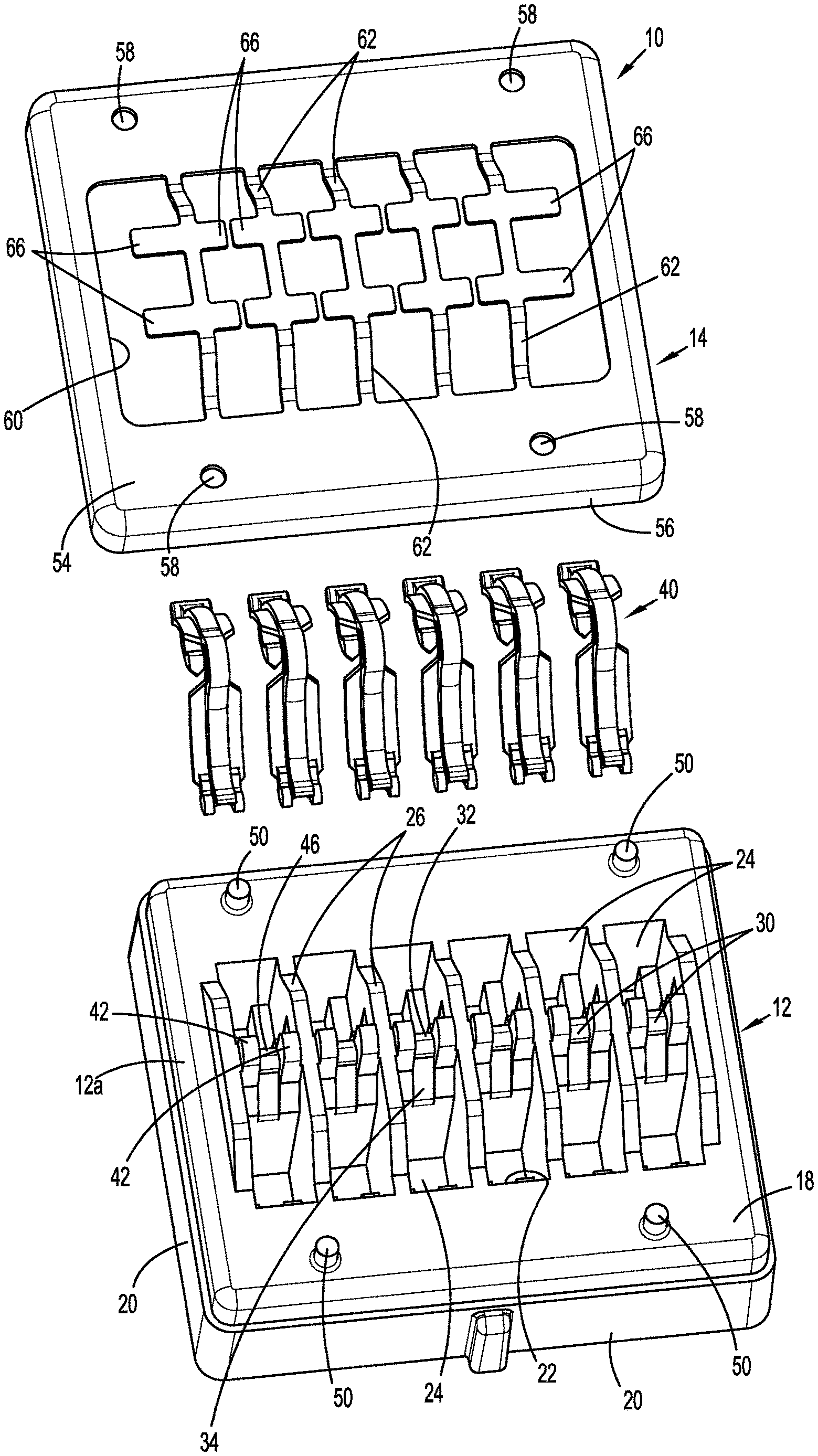
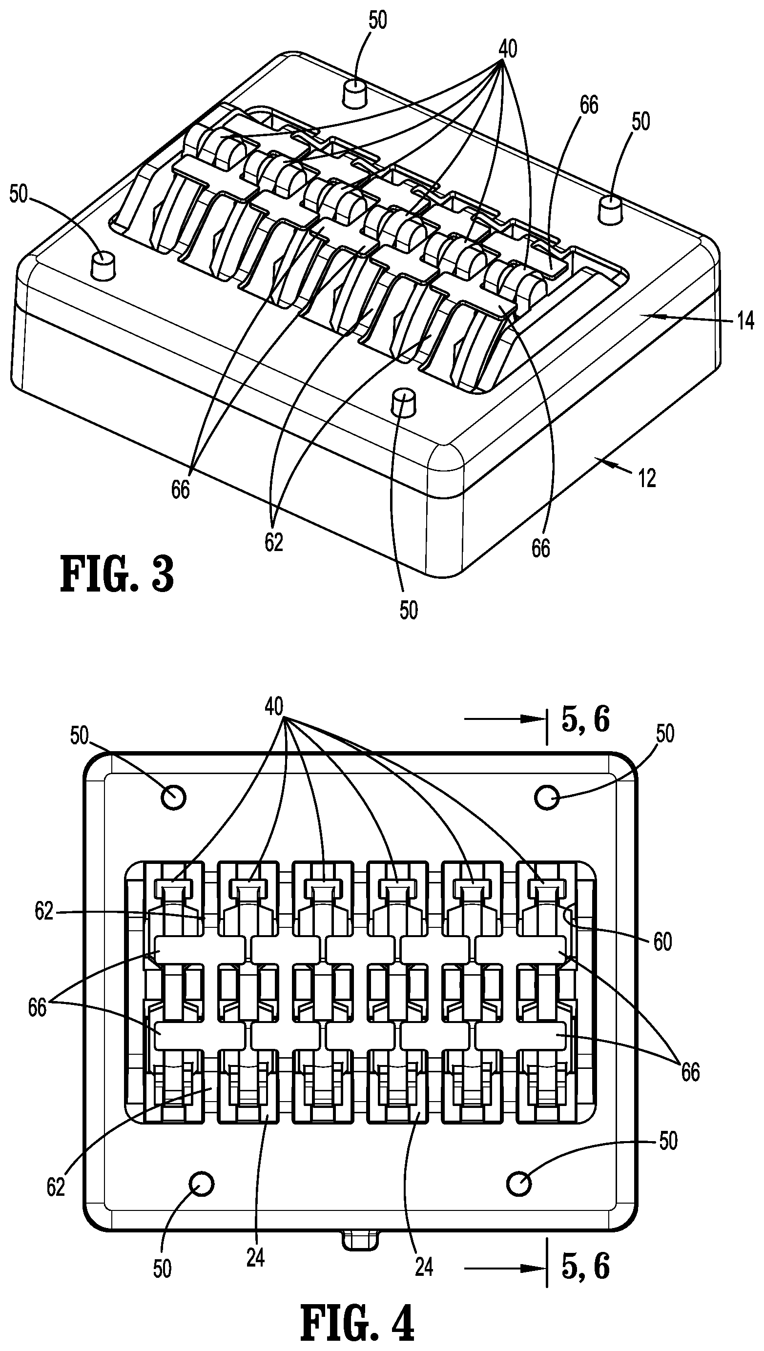
6. The clip cartridge of claim 1, wherein the at least one retainer includes a body that defines an opening that is aligned with the central cavity of the housing, the body including a plurality of resilient strips that extend across the opening, each of the resilient strips supporting the tabs and being aligned with a respective one of the plurality of dividing walls.
7. The clip cartridge of claim 1, wherein the bodies of the housing and of the one retainer are rectangular.
8. The clip cartridge of claim 1, wherein each of the at least one retainer includes an H-shaped body having a central portion, and the tabs are supported on each end of the central portion.
9. The clip cartridge of claim 8, wherein the central portion of each of the at least one retainer is supported on a respective one of the plurality of dividing walls such that the tabs of each of the at least one retainer extend above the clip recesses adjacent to the respective dividing wall.
10. The clip cartridge of claim 9, wherein the central portion of each of the at least one retainer defines an opening and each of the at least one dividing walls includes a protrusion, the opening receiving the protrusion to secure the at least one retainer to the respective dividing wall of the housing.
11. The clip cartridge of claim 1, wherein the at least one retainer is formed of a translucent material.
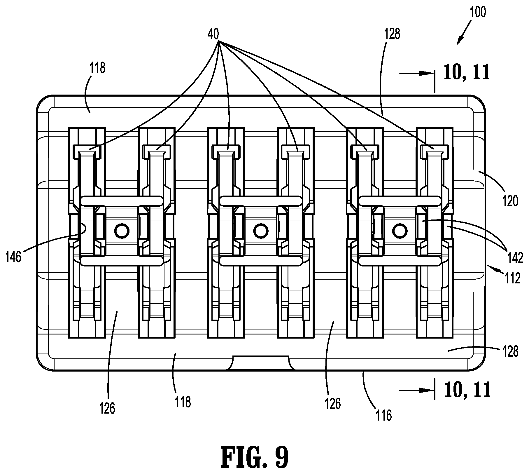
12. A clip cartridge comprising: a housing including a body having side walls defining a central cavity and a plurality of dividing walls extending across the central cavity, each of the plurality of dividing walls defining a transverse axis and forming a clip recess within the central cavity with an adjacent one of the plurality of dividing walls, and a support member positioned within each of the clip recesses, the support member including a first support surface and a second support surface; a clip supported within each of the clip recesses on the support member, each of the clips having a first leg, a second leg, and a hinge portion interconnecting the first leg and the second leg; and a plurality of retainers supported on the housing, each of the plurality of retainers supported on one of the plurality of dividing walls and including tabs that extend in a direction transverse to the transverse axis defined by the plurality of dividing walls, the tabs being positioned to engage the first and second legs of the clips in the clip recesses located adjacent to the dividing wall to urge the first legs of the respective clips onto the first support surfaces of the respective support members and to urge the second legs of the respective clips onto the second support surfaces of the respective support members.
13. The clip cartridge of claim 12, wherein each of the plurality of retainers includes an H-shaped body having a central portion, the tabs supported on each end of the central portion.
14. The clip cartridge of claim 13, wherein the central portion of each of the plurality of retainers defines an opening and each of the plurality of dividing walls includes a protrusion, the opening receiving the protrusion to secure the plurality of retainers to the respective dividing walls of the housing.
15. The clip cartridge of claim 12, wherein the at least one retainer is formed of a translucent material.
16. A clip cartridge comprising; a housing including a body having side walls defining a central cavity and a plurality of dividing walls extending across the central cavity, each of the plurality of dividing walls defining a transverse axis and forming a clip recess within the central cavity with an adjacent one of the plurality of dividing walls, and a support member positioned within each of the clip recesses, the support member including a first support surface and a second support surface; a clip supported within each of the clip recesses of the housing on the support member, each of the clips having a first leg, a second leg, and a hinge portion interconnecting the first and second legs; and a retainer supported on the housing, the retainer having tabs that extend in a direction transverse to the transverse axis defined by the dividing walls, the tabs being positioned to engage the first and second legs of the clips the first leg onto the first support surface and to urge the second leg onto the second support surface of a respective support member.
17. The clip cartridge of claim 16, wherein the retainer includes a body that defines an opening that is aligned with the central cavity of the housing, the body including a plurality of resilient strips that extend across the opening, each of the resilient strips supporting the tabs and being aligned with a respective one of the plurality of dividing walls.
18. The clip cartridge of claim 16, wherein the retainer includes side walls and a top wall, the side walls and the top wall defining a cavity configured to receive an upper end of the housing.
19. The clip cartridge of claim 16, wherein the retainer is formed of a translucent material.
20. The clip cartridge of claim 16, wherein the retainer includes side walls and a top wall that define a cavity that receives an upper end of the housing, the top wall of the retainer defining openings and the housing including a top surface having protrusions, the protrusions received within the openings to secure the retainer to the housing.
Description
FIELD
[0001] This disclosure is directed to a clip cartridge and, more particularly, to a clip cartridge for polymeric ligation clips.
BACKGROUND
[0002] Clip cartridges for supporting polymeric clips are known and typically include a base portion and a retaining member or retaining members. The base portion defines a number of slots that include supporting elements for supporting individual clips within the slots. The retaining member(s) is secured to the base portion and is configured engage a clip or clips to retain the clip or clips within the respective slots of the base portion on the supporting elements. A clip applier is inserted into the slots to remove a clip from the slot and to load a clip onto the clip applier.
[0003] In known clip cartridges, the retaining member(s) applies a load on the clip or clips to retain the clip or clips within the respective slots of the clip cartridge in a compressed or pre-loaded state. The retaining member may also obstruct visualization of the clip within the slot of the staple cartridge which may make loading of a clip into a clip applier difficult.
SUMMARY
[0004] One aspect of the disclosure is directed to a clip cartridge including a housing, at least one retainer, and a plurality of clips. The housing includes a body having side walls defining a central cavity and a plurality of dividing walls extending across the central cavity. Each of the plurality of dividing walls defines a transverse axis and forms a clip recess within the central cavity with an adjacent one of the plurality of dividing walls. A support member is positioned within each of the clip recesses and includes a first support surface and a second support surface. The plurality of clips is supported within the central cavity of the housing, with one clip being supported within each of the clip recesses. Each clip has first and second legs that are interconnected by a hinge portion. The least one retainer is supported on the housing and has tabs that extend in a direction transverse to the transverse axis defined by the dividing walls. The tabs are positioned to engage the first and second legs of the clips to urge the first leg onto the first support surface of a respective support member and to urge the second leg onto the second support surface of a respective support member.
[0005] Another aspect of the disclosure is directed to a clip cartridge including a housing and a retainer. The housing includes a body having side walls defining a central cavity and a plurality of dividing walls extending across the central cavity. Each of the plurality of dividing walls defines a transverse axis and forms a clip recess within the central cavity with an adjacent one of the plurality of dividing walls. A support member is positioned within each of the clip recesses and includes a first support surface and a second support surface. A clip is supported within each of the clip recesses of the housing. Each of the clips has a first leg, a second leg, and a hinge portion interconnecting the first and second legs. The retainer is supported on the housing and has tabs that extend in a direction transverse to the transverse axis defined by the dividing walls. The tabs are positioned to engage the first and second legs of the clips to urge the first leg onto the first support surface of a respective support member and to urge the second leg onto the second support surface of a respective support member.
[0006] Another aspect of the disclosure is directed to a clip cartridge including a housing and a plurality of retainers. The housing includes a body having side walls defining a central cavity and a plurality of dividing walls extending across the central cavity. Each of the plurality of dividing walls defines a transverse axis and forms a clip recess within the central cavity with an adjacent dividing wall. A support member is positioned within each of the clip recesses and includes a first support surface and a second support surface. A clip is supported within each of the clip recesses on the support member. Each of the clips has a first leg, a second leg, and a hinge portion interconnecting the first and the second legs. The plurality of retainers is supported on the housing. Each of the plurality of retainers is supported on one of the plurality of dividing walls and includes tabs that extend in a direction transverse to the transverse axes defined by the plurality of dividing walls. The tabs are positioned to engage the first and second legs of the clips in the clip recesses located adjacent to the dividing wall to urge the first legs of the respective clips onto the first support surfaces of the respective support members and to urge the second legs of the respective clips onto the second support surfaces of the respective support members.
[0007] In aspects of the disclosure, each of the first and second support surfaces of the support member is linear.
[0008] In some aspects of the disclosure, each of the support members includes spacers that are positioned between the dividing walls and define slots that are configured to receive a clip of the plurality of clips, wherein the first and second support surfaces are positioned within the slot.
[0009] In certain aspects of the disclosure, the retainer includes side walls and a top wall that define a cavity that is configured to receive an upper end of the housing.
[0010] In aspects of the disclosure, the top wall of the retainer includes openings and the housing includes a top surface having protrusions, wherein the protrusions are received within the openings to secure the retainer to the housing.
[0011] In some aspects of the disclosure, the retainer includes a body that defines an opening that is aligned with the central cavity of the housing and the body includes a plurality of resilient strips that extend across the opening, wherein each of the resilient strips supports the tabs and is aligned with a respective one of the plurality of dividing walls.
[0012] In certain aspects of the disclosure, the bodies of the housing and of the retainer are rectangular.
[0013] In aspects of the disclosure, each of the retainers includes an H-shaped body having a central portion, and the tabs are supported on each end of the central portion.
[0014] In some aspects of the disclosure, the central portion of each of the retainers is supported on a respective one of the plurality of dividing walls such that the tabs of each of the retainers extend above the clip recesses adjacent to the respective dividing wall.
[0015] In certain aspects of the disclosure, the central portion of each of the at least one retainer defines an opening and each of the at least one dividing wall includes a protrusion, wherein the opening receives the protrusion to secure the at least one retainer to the respective dividing wall of the housing.
[0016] In aspects of the disclosure, the at least one retainer is formed of a translucent material.
[0017] In aspects of the disclosure, the retainer includes a body that defines an opening that is aligned with the central cavity of the housing and the body includes a plurality of resilient strips that extend across the opening, wherein each of the resilient strips supports the tabs and is aligned with a respective one of the plurality of dividing walls.
[0018] Other features of the disclosure will be appreciated from the following description.
BRIEF DESCRIPTION OF THE DRAWINGS
[0019] Various aspects of the disclosed ligation clip cartridge are described herein below with reference to the drawings, wherein:
[0020] FIG. 1 is a perspective first side view from above of an exemplary embodiment of the disclosed ligation clip cartridge;
[0021] FIG. 1A is a side perspective view of an exemplary embodiment of a ligation clip of the ligation clip cartridge shown in FIG. 1;
[0022] FIG. 2 is an exploded perspective view of the ligation clip cartridge shown in FIG. 4;
[0023] FIG. 3 is a perspective second side view from above of the disclosed ligation clip cartridge shown in FIG. 1;
[0024] FIG. 4 is a top view of the clip cartridge shown in FIG. 3;
[0025] FIG. 5 is a cross-sectional view taken along section line 5-5 of FIG. 4;
[0026] FIG. 6 is a cross-sectional view taken along section line 6-6 of FIG. 4;
[0027] FIG. 7 is a perspective first side view from above of another exemplary embodiment of the disclosed ligation clip cartridge;
[0028] FIG. 8 is an exploded perspective view of the ligation clip cartridge shown in FIG. 9;
[0029] FIG. 9 is a top view of the ligation clip cartridge shown in FIG. 8;
[0030] FIG. 10 is a cross-sectional view taken along section line 10-10 of FIG. 9; and
[0031] FIG. 11 is a cross-sectional view taken along section line 11-11 FIG. 9.
DETAILED DESCRIPTION
[0032] The disclosed ligation clip cartridge will now be described in detail with reference to the drawings in which like reference numerals designate identical or corresponding elements in each of the several views. However, it is to be understood that the disclosed aspects are merely exemplary of the disclosure and may be embodied in various forms. Well-known functions or constructions are not described in detail to avoid obscuring the disclosure in unnecessary detail. Therefore, specific structural and functional details disclosed herein are not to be interpreted as limiting, but merely as a basis for the claims and as a representative basis for teaching one skilled in the art to variously employ the disclosure in virtually any appropriately detailed structure. In addition, directional terms such as front, rear, upper, lower, top, bottom, distal, proximal, and similar terms are used to assist in understanding the description and are not intended to limit the disclosure.
[0033] In this description, the term "clinician" is used generally to refer to medical personnel including doctors, nurses, and support personnel.
[0034] FIGS. 1-6 illustrate an exemplary embodiment of the disclosed clip cartridge shown generally as clip cartridge 10. The clip cartridge 10 includes a housing 12 and a retainer 14 that is supported on the housing 12. The housing 12 includes a rectangular body 16 having a top surface 18 (FIG. 2), side walls 20, and a central cavity 22 (FIG. 2) defined by the side walls 20. The central cavity 22 is divided into a plurality of clip recesses 24 by dividing walls 26 that extend upwardly of the top surface 18 of the housing 12 and define transverse axes. Each of the clip recesses 24 includes a support member 30 (FIG. 6) that is positioned between adjacent dividing walls 26 and has a first planar and linear clip support surface 32 (FIG. 5) and a second planar and linear clip support surface 34. The first and second support surfaces 32, 34, respectively, are configured to support legs 38a, 38b of a clip 40 that is supported within the respective clip recess 24. The legs 38a, 38b are coupled together at a hinge portion 38c of the clip 40. The housing 12 also includes spacers 42 (FIG. 2) positioned on each side of the support member 30 that define a slot 46 within the clip recess 24 in which the support member 30 is positioned.
[0035] The housing 12 can be molded from a plastic material such as a thermoplastic material although the use of other materials including metals to form the housing 12 is envisioned. In aspects of the disclosure, the top surface 18 of the housing 12 includes a plurality of protrusions 50 that extend upwardly from the top surface 18. The protrusions 50 are provided to couple the housing 12 to the retainer 14 as described in further detail below.
[0036] The retainer 14 (FIG. 2) is rectangular in shape and includes a top wall 54 and sidewalls 56 that define a cavity configured to receive an upper end 12a (FIG. 2) of the housing 12. The top wall 54 of the retainer 14 includes openings 58 that receive the protrusions 50 to secure the retainer 14 to the top surface 18 (FIG. 2) of the housing 12. Alternately, other securement techniques can be used to secure the retainer 14 to the housing 12 of the clip cartridge 10.
[0037] The top wall 54 of the retainer 14 defines a rectangular opening 60 that is aligned with the central cavity 22 of the housing 12 to provide access to the central cavity 22 and includes a plurality of resilient strips 62 that extend across the opening 60. Each of the resilient strips 62 is aligned with one of the dividing walls 26 of the housing 12 when the retainer 14 is secured to the housing 12 and includes spaced tabs 66. The spaced tabs 66 extend in a direction transverse to the dividing wall 26 to opposite sides of the dividing wall 26 to positions atop the legs 38a, 38b of the clips 40 received in the slots 46.
[0038] In aspects of the disclosure, the resilient strips 62 extend upwardly from the top wall 54 of the retainer 12 along the respective dividing walls 26 to position the tabs 66 in engagement with the legs 38a, 38b of each of the clips 40 at a location adjacent the hinge portion 38c of the clip 40. When the retainer 14 is attached to the housing 12, the tabs 66 of the retainer 14 press downwardly on the legs 38a, 38b of the clips 40 to urge the clip 40 onto the support surfaces 32, 34 of the support member 30 to retain the clips 40 within the clip cartridge 10 in an unbiased, unclamped state.
[0039] During loading of a clip 40 between the jaws of a clip applier (not shown), the jaws of the clip applier are inserted into a clip recess 24 to access a clip 40. The tabs 66 of the retainer 14 are formed of a resilient material and will deform outwardly upon removal of a clip 40 from a recess 24 of the housing 12. In aspects of the disclosure, the retainer 14 is formed of a translucent material to allow a clinician to more easily visualize a clip 40 within the housing 12 of the clip cartridge 10 during loading.
[0040] FIGS. 7-11 illustrate another exemplary embodiment of the disclosed clip cartridge which is shown generally as clip cartridge 100. The clip cartridge 100 includes a housing 112 and a plurality of retainers 114 that are supported on the housing 112. The housing 112 includes a rectangular body 116 having longitudinal side walls 118 and transverse side walls 120 that define a central cavity 122. The central cavity 122 is divided into a plurality of clip recesses 124 by dividing walls 126, each of which define a transverse axis. The transverse side walls 120 and the dividing walls 126 extend upwardly of a top surface 128 of the longitudinal side walls 118 of the housing 112. Each of the clip recesses 124 includes a support member 130 that is positioned between adjacent dividing walls 126 and has a first linear clip support surface 132 (FIG. 10) and a second linear clip support surface 134. The first and second support surfaces 132, 134, respectively, are configured to support legs 38a, 38b of clips 40 supported within the respective clip recesses 124 as described above in regard to support surfaces 32, 34 (FIG. 6). As described above, the legs 38a, 38b of the clips 40 are coupled together at a hinge portion 38c of the clips 40. The support member 130 also includes spacers 142 positioned on each side of the support member 130 between the dividing walls 126 that define slots 146 within which the support members 130 are positioned.
[0041] Each of the dividing walls 126 includes a central portion 148 located between the longitudinal side walls 118 of the housing 112. The central portion 148 supports a protrusion 150 that extends upwardly from the dividing wall 126. The protrusions 150 are provided to couple the retainers 114 to the housing 112.
[0042] Each of the retainers 114 has a resilient H-shaped body 154 (FIG. 8) including a central body portion 156 and tabs 166 supported at each end of the central body portion 156. The central body portion 156 of each of the retainers 114 defines a bore 158 that receives one of the protrusions 150 extending from the central portion 148 of a respective dividing wall 126 to secure the retainer 114 to the dividing wall 126. When the retainers 114 are attached to the dividing walls 126 of the housing 112 of the clip cartridge 100, the tabs 166 of the retainers 114 press downwardly on the legs 38a, 38b of the clips 40 in the clip recesses 124 on each side of the respective dividing wall 126 to urge the clip 40 onto the support surfaces 132, 134 of the support member 130 to retain the clips 40 within the clip cartridge 100 in an unbiased state.
[0043] During loading of a clip 40 between the jaws of a clip applier (not shown), the jaws of the clip applier are inserted into a clip recess 124 to access a clip 40. The tabs 166 of the retainer 114 associated with the clip recess 124 are formed of a resilient material and will deform outwardly upon removal of the clip 40 from the recess 24 of the housing 112. In aspects of the disclosure, the retainer 114 is formed of a translucent material to allow a clinician to more easily visualize a clip 40 within the housing 112 of the clip cartridge 100 during loading.
[0044] The disclosed exemplary aspects of the disclosure of the ligation clip cartridge retain clips within the cartridge in an unbiased state to minimize damage to the clip material caused by strain on the clip. As such, the clip can be stored for longer periods of time.
[0045] Persons skilled in the art will understand that the devices and methods specifically described herein and illustrated in the accompanying drawings are non-limiting exemplary aspects of the disclosure. It is envisioned that the elements and features illustrated or described in connection with one exemplary embodiment may be combined with the elements and features of another without departing from the scope of the disclosure. As well, one skilled in the art will appreciate further features and advantages of the disclosure based on the above-described aspects of the disclosure. Accordingly, the disclosure is not to be limited by what has been particularly shown and described, except as indicated by the appended claims.
* * * * *
D00000
D00001
D00002
D00003
D00004
D00005
D00006
D00007
D00008
XML
uspto.report is an independent third-party trademark research tool that is not affiliated, endorsed, or sponsored by the United States Patent and Trademark Office (USPTO) or any other governmental organization. The information provided by uspto.report is based on publicly available data at the time of writing and is intended for informational purposes only.
While we strive to provide accurate and up-to-date information, we do not guarantee the accuracy, completeness, reliability, or suitability of the information displayed on this site. The use of this site is at your own risk. Any reliance you place on such information is therefore strictly at your own risk.
All official trademark data, including owner information, should be verified by visiting the official USPTO website at www.uspto.gov. This site is not intended to replace professional legal advice and should not be used as a substitute for consulting with a legal professional who is knowledgeable about trademark law.