Livestock Blower Apparatus
Johnson; Jermiah ; et al.
U.S. patent application number 16/406570 was filed with the patent office on 2020-11-12 for livestock blower apparatus. This patent application is currently assigned to Xceed Engineering LLC. The applicant listed for this patent is Xceed Engineering LLC. Invention is credited to Brian Birk, Lance Harris, Jermiah Johnson, Mike Ott.
| Application Number | 20200352132 16/406570 |
| Document ID | / |
| Family ID | 1000004055422 |
| Filed Date | 2020-11-12 |


View All Diagrams
| United States Patent Application | 20200352132 |
| Kind Code | A1 |
| Johnson; Jermiah ; et al. | November 12, 2020 |
Livestock Blower Apparatus
Abstract
A livestock blower apparatus for blowing air through a flexible hose onto an animal. A pair of blower units are enclosed within an interior space of a housing. The blower units are adapted to draw air through housing inlet openings and force it through a Y-shaped conduit out through a housing outlet opening without the air coming in contact with the housing interior space. A cooling fan is provided at a housing cooling inlet opening and blows air into the housing interior space. Another cooling fan is provided at a housing cooling outlet opening and draws/blows air out from within the housing interior space. The blower units are thereby protected from the elements and noise generated by them is muffled by the housing, and the blower units are cooled for minimizing the heat that may be transferred to the air being blown onto the animal.
| Inventors: | Johnson; Jermiah; (Churubusco, IN) ; Birk; Brian; (Goshen, IN) ; Harris; Lance; (Albion, IN) ; Ott; Mike; (Albion, IN) | ||||||||||
| Applicant: |
|
||||||||||
|---|---|---|---|---|---|---|---|---|---|---|---|
| Assignee: | Xceed Engineering LLC Churubusco IN |
||||||||||
| Family ID: | 1000004055422 | ||||||||||
| Appl. No.: | 16/406570 | ||||||||||
| Filed: | May 8, 2019 |
| Current U.S. Class: | 1/1 |
| Current CPC Class: | F04D 29/584 20130101; A01K 13/001 20130101; F04D 29/703 20130101; A01K 1/0052 20130101; F04D 25/166 20130101; F04D 25/06 20130101; F04D 29/403 20130101 |
| International Class: | A01K 13/00 20060101 A01K013/00; F04D 25/16 20060101 F04D025/16; F04D 25/06 20060101 F04D025/06; F04D 29/40 20060101 F04D029/40; F04D 29/58 20060101 F04D029/58; F04D 29/70 20060101 F04D029/70 |
Claims
1. A blower apparatus for blowing air onto animals comprising: a blower housing defining an enclosed interior space and having a blower air inlet opening, a blower air outlet opening, a cooling air inlet opening and a cooling air outlet opening; a blower unit comprising a fan selectively driven by an electric motor, wherein said fan includes a fan housing having an air inlet and an air outlet and wherein said electric motor is located outside of the fan housing; said blower unit is located within said blower housing interior space whereby said blower unit is protected by said blower housing; said fan housing inlet communicates with said blower housing air inlet opening and said fan housing outlet communicates with said blower housing air outlet opening, whereby air is drawn in through said blower housing air inlet opening and forced out through said blower housing air outlet opening without contacting air within said blower housing interior space; and, a cooling fan at one of said blower housing cooling air inlet opening or blower housing cooling air outlet opening drawing air into said blower housing interior space through said blower housing cooling air inlet and forcing air out from within said blower housing interior space through said blower housing cooling air outlet opening, whereby heat generated by said blower unit is removed from said blower housing interior space and said blower unit is cooled.
2. The blower apparatus of claim 1 wherein said blower unit is a tangential bypass flow motor fan.
3. The blower apparatus of claim 1 further comprising an elongate flexible air hose connected to said blower housing air outlet opening at its one terminal end thereof and having a reduced opening nozzle at its other terminal end thereof.
4. The blower apparatus of claim 1 further comprising an air filter selectively placeable over said blower housing air inlet opening.
5. The blower apparatus of claim 1 further comprising a second cooling fan at the other one of said blower housing cooling air inlet opening or blower housing cooling air outlet opening, whereby the cooling fan at the blower housing cooling air inlet forces air into said housing interior space and the cooling fan at the blower housing cooling air outlet forces air out from within said housing interior space.
6. The blower apparatus of claim 1 wherein said blower housing comprises an integrally formed handle.
7. The blower apparatus of claim 1 wherein said blower housing comprises a pair of integrally formed halves secured to each other with fasteners.
8. The blower apparatus of claim 1 wherein said blower unit is a tangential bypass flow motor fan; and, further comprising an air filter selectively placeable over said blower housing air inlet opening.
9. A blower apparatus for blowing air onto animals comprising: a blower housing defining an enclosed interior space and having first and second blower air inlet openings, a blower air outlet opening, a cooling air inlet opening and a cooling air outlet opening; first and second blower units wherein each blower unit comprises a fan selectively driven by an electric motor, wherein said fan includes a fan housing having an air inlet and an air outlet and wherein said electric motor is located outside of the fan housing; said first and second blower units are located within said blower housing interior space whereby said blower units are protected by said blower housing; said first blower unit fan inlet communicates with said first blower housing air inlet opening; said second blower unit fan inlet communicates with said second blower housing air inlet opening; both said first blower unit fan outlet and said second blower unit fan outlet communicate with said blower housing air outlet opening, whereby air is drawn in through said blower housing first and second air inlet openings and is forced out through said blower housing air outlet opening without contacting air within said blower housing interior space and; and, a cooling fan at one of said blower housing cooling air inlet opening or blower housing cooling air outlet opening drawing air into said blower housing interior space through said blower housing cooling air inlet and forcing air out from within said blower housing interior space through said blower housing cooling air outlet opening, whereby heat generated by said first and second blower units is removed from said blower housing interior space and said first and second blower units are cooled.
10. The blower apparatus of claim 9, further comprising a Y-shaped conduit having: a first opening communicating with said first blower unit fan outlet; a second opening communicating with said second blower unit fan outlet; and, a third opening communicating with said blower housing air outlet opening.
11. The blower apparatus of claim 9 wherein said first and second blower units are tangential bypass flow motor fans.
12. The blower apparatus of claim 9 further comprising an elongate flexible air hose connected to said blower housing air outlet opening at its one terminal end thereof and having a reduced opening nozzle at its other terminal end thereof.
13. The blower apparatus of claim 9 further comprising a first air filter selectively placeable over said first blower housing air inlet opening and a second air filter selectively placeable over said second blower housing air inlet opening.
14. The blower apparatus of claim 9 further comprising a second cooling fan at the other one of said blower housing cooling air inlet opening or blower housing cooling air outlet opening, whereby the cooling fan at the blower housing cooling air inlet forces air into said housing interior space and the cooling fan at the blower housing cooling air outlet forces air out from within said housing interior space.
15. The blower apparatus of claim 9 wherein said blower housing comprises an integrally formed handle.
16. The blower apparatus of claim 9 wherein said blower housing comprises a pair of integrally formed halves secured to each other with fasteners.
17. The blower apparatus of claim 9 wherein said first and second blower units are tangential bypass flow motor fans; and, further comprising a first air filter selectively placeable over said first blower housing air inlet opening and a second air filter selectively placeable over said second blower housing air inlet opening.
18. The blower apparatus of claim 9, further comprising: a Y-shaped conduit having: a first opening communicating with said first blower unit fan outlet; a second opening communicating with said second blower unit fan outlet; and, a third opening communicating with said blower housing air outlet opening; and, wherein said first and second blower units are tangential bypass flow motor fans.
19. The blower apparatus of claim 9, further comprising: a Y-shaped conduit having: a first opening communicating with said first blower unit fan outlet; a second opening communicating with said second blower unit fan outlet; and, a third opening communicating with said blower housing air outlet opening; wherein said first and second blower units are tangential bypass flow motor fans; and, a second cooling fan at the other one of said blower housing cooling air inlet opening or blower housing cooling air outlet opening, whereby the cooling fan at the blower housing cooling air inlet forces air into said housing interior space and the cooling fan at the blower housing cooling air outlet forces air out from within said housing interior space.
20. The blower apparatus of claim 9, further comprising: a Y-shaped conduit having: a first opening communicating with said first blower unit fan outlet; a second opening communicating with said second blower unit fan outlet; and, a third opening communicating with said blower housing air outlet opening; wherein said first and second blower units are tangential bypass flow motor fans; a second cooling fan at the other one of said blower housing cooling air inlet opening or blower housing cooling air outlet opening, whereby the cooling fan at the blower housing cooling air inlet forces air into said housing interior space and the cooling fan at the blower housing cooling air outlet forces air out from within said housing interior space; and, an elongate flexible air hose connected to said blower housing air outlet opening at its one terminal end thereof and having a reduced opening nozzle at its other terminal end thereof.
Description
BACKGROUND OF THE INVENTION
1. Field of the Invention
[0001] The present invention relates to the field of blowers used for blowing and directing air onto animals/livestock for cooling and drying the animals and for removing dirt from and grooming the animals.
2. Background
[0002] Animal/livestock blowers are known and are commonly used primarily at events such as shows, sales and/or auctions to groom the animal by drying and/or removing dirt/debris and thereby enhancing the appearance of the skin/hair of the animal. Hand held self-contained blowers have been used for this purpose. However, they tend to be cumbersome and heavy, they do not provide a sufficient volume of air, especially for larger animals, and can spook the animal by the noise they generate. Separate air blower apparatus have therefore been devised which can be located away from the animal. An air hose is used for delivering the air from the blower apparatus to and around the animal as needed or desired. Examples of such known blower apparatus are shown and described in Chen, U.S. D792,662; Sack, U.S. Pat. No. 8,631,767; Denison et at., US 2012/0031347; Davis Jr., U.S. Pat. No. 4,977,690; and, Di Peso, U.S. Pat. No. 5,926,972.
[0003] The prior air blower apparatus, however, typically intend to or otherwise inadvertently heat the air being delivered. This is undesirable, especially in hot weather, when cool air is preferable for cooling and calming the animal. The life of some of the prior air blower apparatus is also often shortened due to dirt and debris fouling the blower motor(s).
[0004] Accordingly, a need exists for an improved livestock blower apparatus which overcomes the foregoing and other disadvantageous of prior livestock blower apparatus, and which delivers relatively cooler air to the animal and which protects the blower(s) and increases the life of the apparatus.
SUMMARY OF THE INVENTION
[0005] The present invention overcomes disadvantageous of prior livestock blower apparatus by isolating the air being drawn into the blower apparatus and being delivered onto the animal from the motor and other components of the apparatus which function to draw and deliver/force the air to the animal; enclosing and protecting the motor and other components from the elements; and, cooling the motor and components to minimize the heat that may be transferred from the motor and other components to the air being delivered onto the animal.
[0006] In one form thereof, the present invention is directed to a blower apparatus for blowing air onto animals and includes a blower housing defining an enclosed interior space and having a blower air inlet opening, a blower air outlet opening, a cooling air inlet opening and a cooling air outlet opening. A blower unit is provided including a fan selectively driven by an electric motor, wherein the fan includes a fan housing having an air inlet and an air outlet and wherein the electric motor is located outside of the fan housing. The blower unit is located within the blower housing interior space whereby the blower unit is protected by the blower housing. The fan housing inlet communicates with the blower housing air inlet opening and the fan housing outlet communicates with the blower housing air outlet opening, whereby air is drawn in through the blower housing air inlet opening and forced out through the blower housing air outlet opening without contacting air within the blower housing interior space. A cooling fan is provided at one of the blower housing cooling air inlet opening or blower housing cooling air outlet opening for drawing air into the blower housing interior space through the blower housing cooling air inlet and forcing air out from within the blower housing interior space through the blower housing cooling air outlet opening, whereby heat generated by the blower unit is removed from the blower housing interior space and the blower unit is cooled.
[0007] In another form thereof, the present invention is directed to a blower apparatus for blowing air onto animals and includes a blower housing defining an enclosed interior space and having first and second blower air inlet openings, a blower air outlet opening, a cooling air inlet opening and a cooling air outlet opening. First and second blower units are provided wherein each blower unit includes a fan selectively driven by an electric motor, wherein the fan includes a fan housing having an air inlet and an air outlet and wherein the electric motor is located outside of the fan housing. The first and second blower units are located within the blower housing interior space whereby the blower units are protected by the blower housing. The first blower unit fan inlet communicates with the first blower housing air inlet opening. The second blower unit fan inlet communicates with the second blower housing air inlet opening. Both the first blower unit fan outlet and the second blower unit fan outlet communicate with the blower housing air outlet opening, whereby air is drawn in through the blower housing first and second air inlet openings and is forced out through the blower housing air outlet opening without contacting air within the blower housing interior space. A cooling fan is provided at one of the blower housing cooling air inlet opening or blower housing cooling air outlet opening for drawing air into the blower housing interior space through the blower housing cooling air inlet and forcing air out from within the blower housing interior space through the blower housing cooling air outlet opening, whereby heat generated by the first and second blower units is removed from the blower housing interior space and the first and second blower units are cooled.
[0008] Preferably, a Y-shaped conduit is provided having: a first opening communicating with the first blower unit fan outlet; a second opening communicating with the second blower unit fan outlet; and, a third opening communicating with the blower housing air outlet opening.
[0009] The first and second blower units are preferably tangential bypass flow motor fans.
[0010] The apparatus may further include an elongate flexible air hose connected to the blower housing air outlet opening at its one terminal end thereof and having a reduced opening nozzle at its other terminal end thereof.
[0011] Also preferably, a first air filter selectively placeable over the first blower housing air inlet opening and a second air filter selectively placeable over the second blower housing air inlet opening.
[0012] A second cooling fan is also preferably provided at the other one of the blower housing cooling air inlet opening or blower housing cooling air outlet opening, whereby the cooling fan at the blower housing cooling air inlet forces air into the housing interior space and the cooling fan at the blower housing cooling air outlet forces air out from within the housing interior space.
[0013] The blower housing preferably comprises a pair of integrally formed halves secured to each other with fasteners and an integrally formed handle.
BRIEF DESCRIPTION OF THE DRAWINGS
[0014] The above mentioned and other features and objects of this invention, and the manner of attaining them, will become more apparent and the invention itself will be better understood by reference to the following description of the embodiments of the invention taken in conjunction with the accompanying drawings, wherein:
[0015] FIG. 1 is a left side elevation view of a livestock blower apparatus constructed in accordance with the principles of the present invention and showing a hose connected thereto for delivering/blowing air onto a remotely located animal;
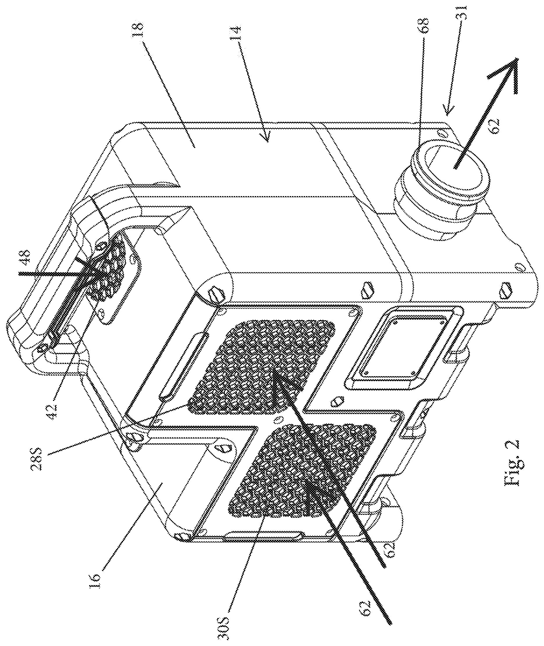
[0016] FIG. 2 is a perspective view of the blower apparatus shown in FIG. 1 and showing the front, left side and top thereof;
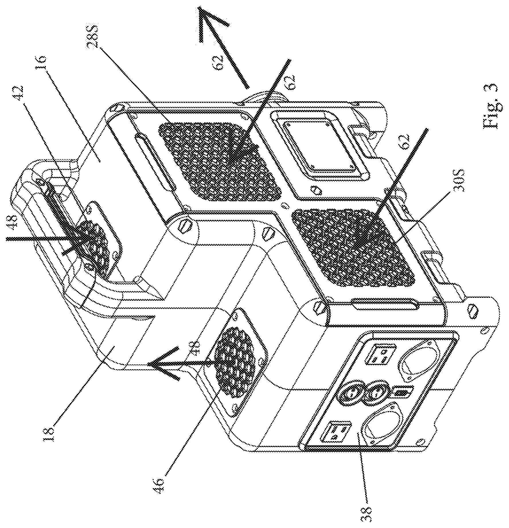
[0017] FIG. 3 is another perspective view of the blower apparatus shown in FIG. 1 and showing the rear, left side and top thereof;
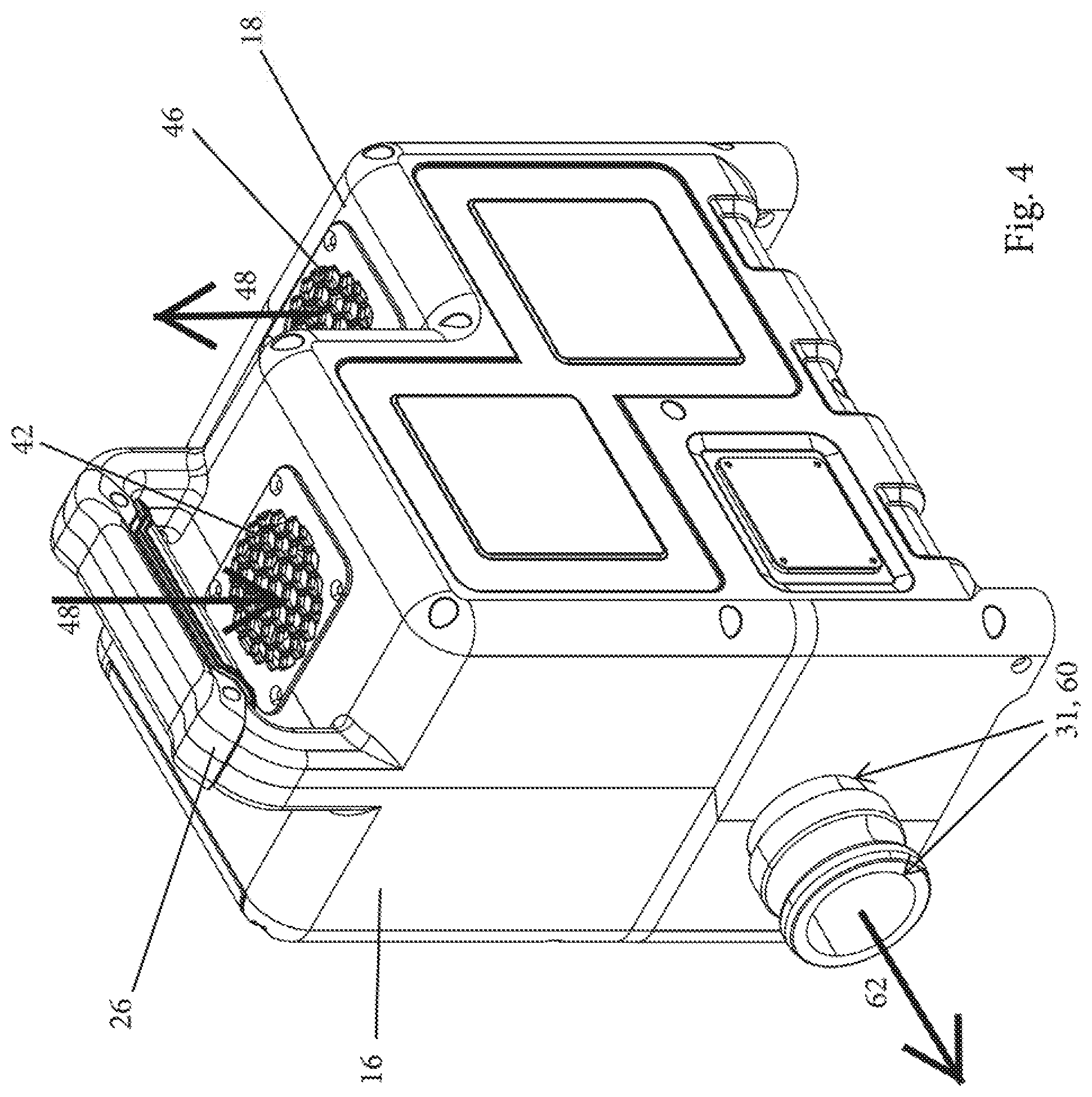
[0018] FIG. 4 is another perspective view of the blower apparatus shown in FIG. 1 and showing the front, right side and top thereof;
[0019] FIG. 5 is another perspective view of the blower apparatus shown in FIG. 1 and showing the rear, right side and top thereof;
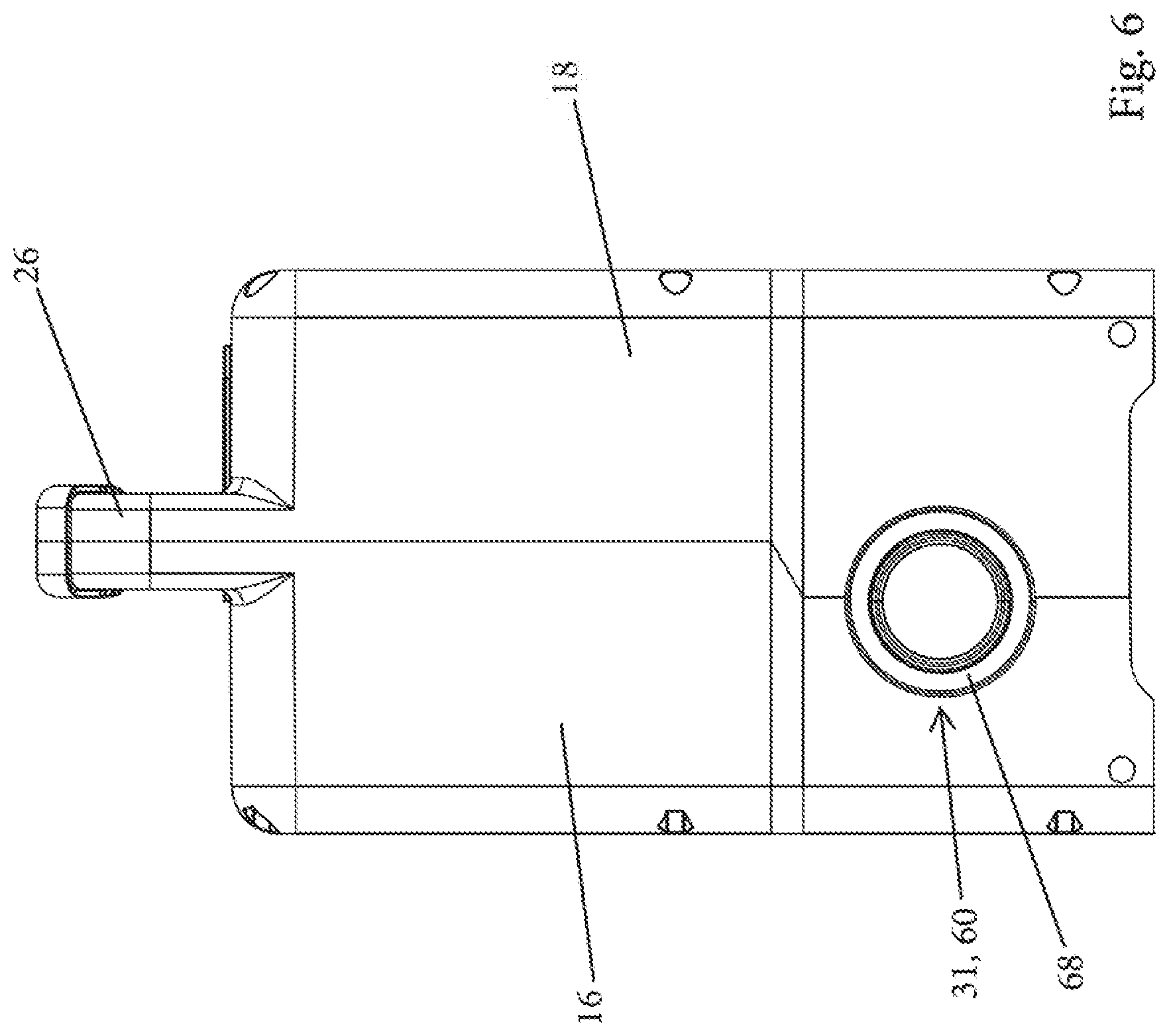
[0020] FIG. 6 is a front elevation view of the blower apparatus shown in FIG. 1;
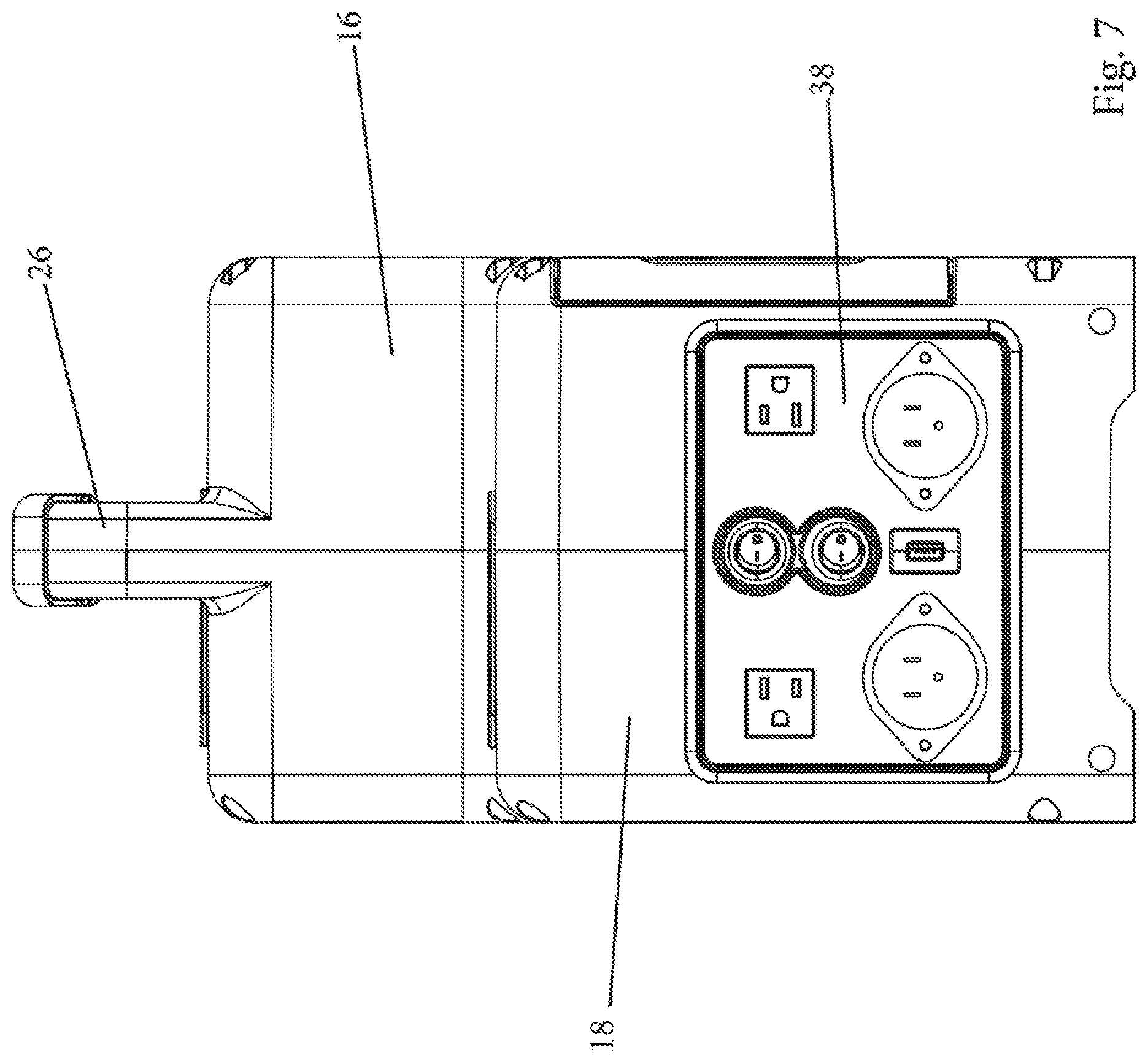
[0021] FIG. 7 is a rear elevation view of the blower apparatus shown in FIG. 1;
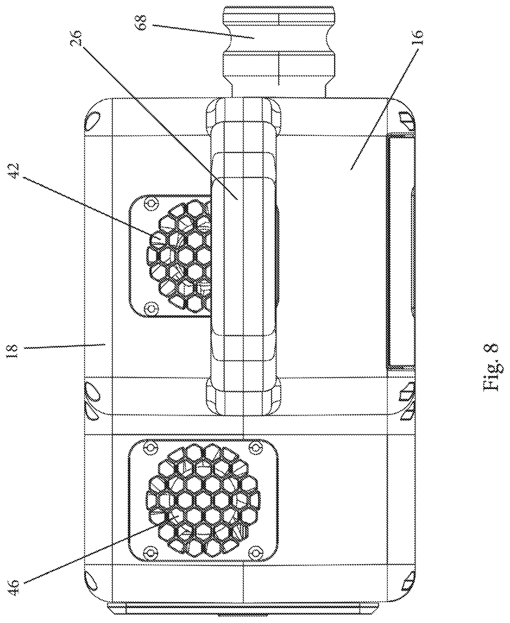
[0022] FIG. 8 is a top plan view of the blower apparatus shown in FIG. 1;
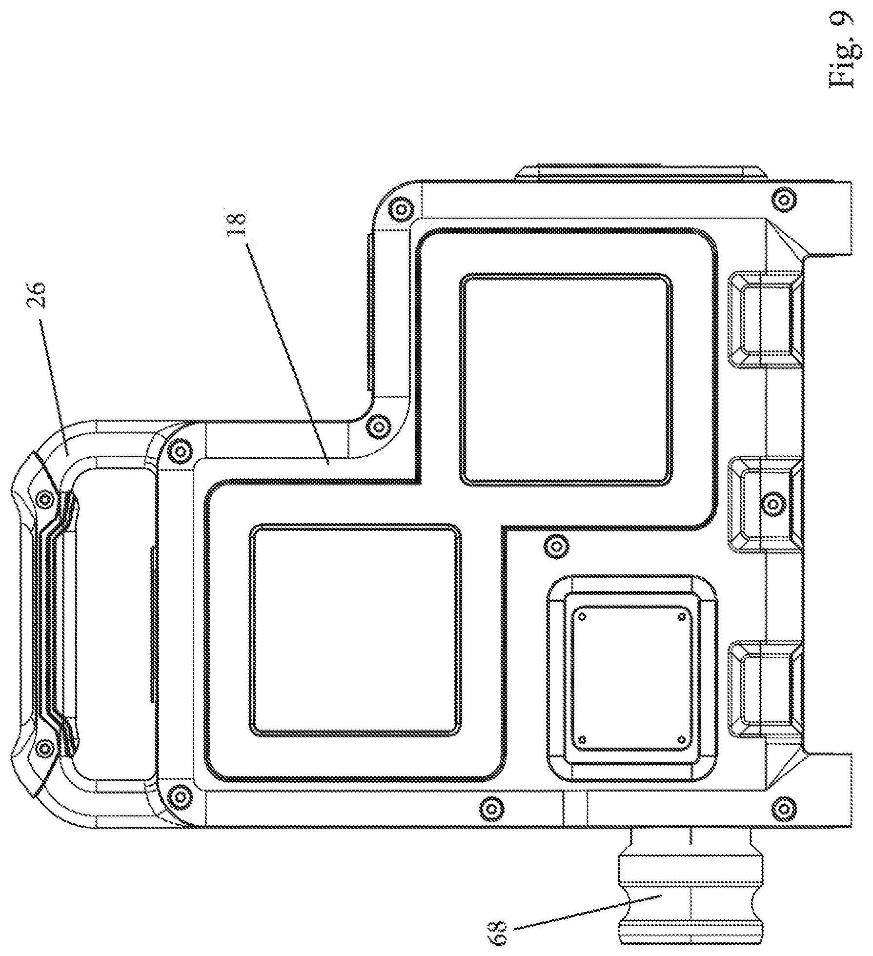
[0023] FIG. 9 is a right side elevation view of blower apparatus shown in FIG. 1 showing the right housing half;
[0024] FIG. 10 is a left side elevation view of blower apparatus shown in FIG. 1 showing the left housing half;
[0025] FIG. 11 is an exploded view of the blower apparatus shown in FIG. 1 depicting the assembly of the several components thereof;
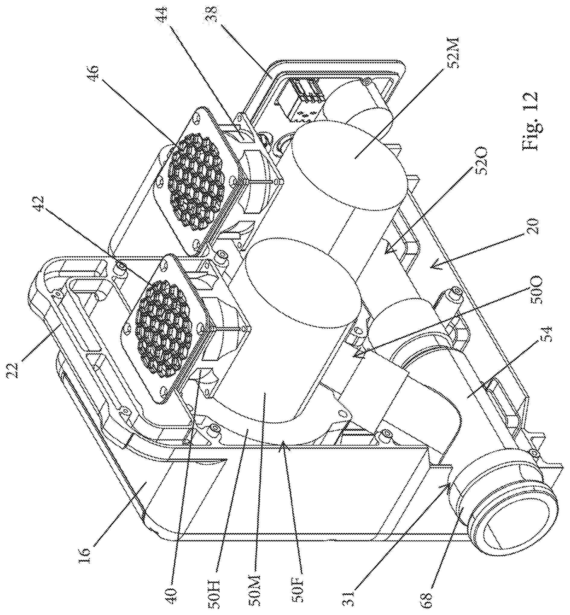
[0026] FIG. 12 is a perspective view similar to FIG. 4 with the right housing half removed;
[0027] FIG. 13 is a perspective view similar to FIG. 5 with the right housing half removed;
[0028] FIG. 14 is a right side elevation view similar to FIG. 9 with the right housing half removed; and,
[0029] FIG. 15 is a perspective view similar to FIG. 3 and depicting the air filters slidably insertable into a slot for placing them over the blower housing air inlet openings.
[0030] Corresponding reference characters indicate corresponding parts throughout several views. Although the exemplification set out herein illustrates embodiments of the invention, in several forms, the embodiments disclosed below are not intended to be exhaustive or to be construed as limiting the scope of the invention to the precise forms disclosed.
DETAILED DESCRIPTION OF THE PREFERRED EMBODIMENTS
[0031] Referring initially to FIG. 1, a livestock blower apparatus constructed in accordance with the principles of the present invention is shown and designated by the numeral 10. Apparatus 10, as more fully described herein below, is adapted to blow/force air through a flexible air hose 12 for thereby directing and blowing the air onto an animal for cooling and drying the animal and for removing dirt from and grooming the animal.
[0032] Apparatus 10 includes a blower housing 14 which, as best seen in FIG. 11, is constructed with a pair of plastic molded housing halves, namely, left housing half 16 and right housing half 18. Left housing half 16 and right housing half 18 are secured to each other with fasteners (not numbered). Housing 14 thereby defines an enclosed interior space 20. Left and right housing halves 16, 18 include respective integrally formed handle halves, namely, left handle half 22 and right handle half 24. When the left and right housing halves 16, 18 are secured to each other, the left and right handle halves 22, 24 form a carrying handle 26.
[0033] The left housing half 16 includes first and second blower air inlet openings 28, 30. When the left and right housing halves 16, 18 are secured to each other, the housing 14 forms and includes a blower air outlet opening 31, a cooling air inlet opening 32, a cooling air outlet opening 34 and a control panel opening 36. A control panel 38 is provided for mounting the control components and controlling the blower apparatus 10 as needed or desired. Control panel 38 is secured to the housing 14 at the control panel opening 36 and thereby also fills/seals the opening 36.
[0034] A cooling axial fan 40 is provided at the housing cooling air inlet opening 32 and is adapted to blow/force air into the housing interior space 20 when energized. A screen 42 is mounted over the cooling axial fan 40 with fasteners (not numbered) for preventing dirt and debris from being drawn into the housing interior space 20 and for safety purposes. A cooling axial fan 44 is provided at the housing cooling air outlet opening 34 and is adapted to blow/force air out from within the housing interior space 20 when energized. A screen 46 is mounted over the cooling axial fan 44 with fasteners (not numbered) primarily for safety purposes and also for preventing dirt and debris from inadvertently entering the housing interior space 20. As should now be appreciated, a cooling air flow path depicted in the drawings with arrows 48 is formed with cooling axial fans 40, 42 forcing ambient air through the housing cooling air inlet opening 32 into the housing interior space 20 and around the blower units 50, 52 and other components within the interior space 20, and then out from the interior space 20 through the housing cooling air outlet 34. As should also be appreciated, although it is preferable to use both cooling axial fans 40, 42 for maximizing the velocity and volume of air traversing the cooling air flow path 48, it is contemplated that only one of the cooling axial fans 40, 42 can be used if a lower velocity and a lesser volume of air is found to be sufficient.
[0035] Blower units 50, 52 are provided and are located within the housing interior space 20. Blower units 50, 52 are mounted onto the left housing half 16 with fasteners (not numbered). Blower units 50, 52 are preferably tangential bypass flow motor fans such as model No. 122525-00 available from AMETEK Dynamic Fluid Solutions, 100 East Erie St., Kent, Ohio 44240. Each of the blower units 50, 52 are made up of and include a fan 50F, 52F which is selectively driven by an electric motor 50M, 52M. The fans 50F, 52F include a fan housing 50H, 52H having an air inlet 501, 521 and an air outlet 500, 520. The electric motors 50M, 52M are located outside of the fan housing 50H, 52H. That is, substantially only the motor shaft extends into the fan housing 50H, 52H for rotatably driving the impeller (not shown) as is common in tangential bypass flow motor fans. Accordingly, air traveling through the fan housing 50H, 52H is effectively sealed from the motor 50M, 52M. Motors 50M, 52M may be provided with internal cooling fans for discarding heat created by the motors (not shown) as is also common in tangential bypass flow motor fans.
[0036] The blower units 50, 52 are mounted onto the left blower housing 16 with the blower fan inlets 501, 521 being aligned with and communicating with respective blower housing inlet openings 28, 30 whereby, when the blower units are energized, air is drawn into the fans 50F, 52F through the respective blower housing inlet openings 28, 30 and respective fan housing inlets 501, 521. The air drawn into the blower units 50, 52 is forced out through respective blower fan outlets 500, 520 and is directed to and discharged out of the blower housing 14 through the blower air outlet opening 31. More particularly and preferably, a Y-shaped conduit 54 is provided and is mounted within the housing 14. Y-shaped conduit 54 has a first opening 56 connected to and communicating with the blower unit 50 fan outlet 500, a second opening 58 connected to and communicating with the blower unit 52 fan outlet 520 and, a third opening 60 extending through/communicating with the blower housing air outlet opening 31. Accordingly, the Y-shaped conduit serves to converge the air blown/forced out of the blower fan outlets 500, 520 into a single air stream which is discharged through the Y-shaped conduit third opening 60 and the blower housing air outlet opening 31.
[0037] Screens 28S, 30S are mounted over the respective blower air inlet openings 28, 30 with fasteners (not numbered) for preventing dirt and debris from being drawn into the respective blower unit fans 50F, 52F and for safety purposes. Screens 28S, 30S are preferably integrally formed together as shown for minimizing costs and aesthetic appearance purposes. Additionally, air filters 28F, 30F are selectively placed over the respective blower unit air inlet openings 28, 30 by grasping the respective handle 28H, 30H thereof and sliding into and out of respective slots 64, 66 formed between the screens 28S, 30S and the left housing half 16. Filters 28F, 30F further prevent dirt and debris from being drawn into the respective blower unit fans 50F, 52F.
[0038] As should now be appreciated, a blower air flow path depicted in the drawings with arrows 62 is formed through the housing interior space 20 with the blower units 50, 52 drawing air in through the blower housing inlet openings 28, 30 and forcing it into the Y-shaped conduit 54 and then out of through the blower housing outlet 31. Also, the air traveling along the blower air flow path 62 does not contact/is not exposed to the blower housing interior space 20 and hence does not communicate with the air traveling along the cooling air flow path 48. Accordingly, the blower units 50, 52 are protected from the elements and are safely located within the housing 14. Additionally, the noise created by blower units 50, 52 is muffled by the housing 14.
[0039] The apparatus 10 is used by directing the air blown/forced out of the blower housing outlet 31 through a flexible air hose 12 and thereby directing and blowing the air onto an animal for cooling and drying the animal and for removing dirt from and grooming the animal. Preferably, a male quick connect pipe coupling 68 is provided at the Y-shaped conduit third opening 60 and the hose 12 is provided with a corresponding female quick connect pipe coupling 70 at one of its terminal ends 72 for thereby quickly and easily connecting the hose terminal end 70 to the conduit third opening 60/blower housing outlet opening 31. The air hose 12 other terminal end 74 is provided with a reduced opening nozzle 76 for increasing the velocity of the air being discharged therethrough and onto an animal.
[0040] While this invention has been described as having an exemplary design, the present invention may be further modified within the spirit and scope of this disclosure. This application is therefore intended to cover any variations, uses, or adaptations of the invention using its general principles.
* * * * *
D00000
D00001
D00002
D00003
D00004
D00005
D00006
D00007
D00008
D00009
D00010
D00011
D00012
D00013

D00014

D00015

XML
uspto.report is an independent third-party trademark research tool that is not affiliated, endorsed, or sponsored by the United States Patent and Trademark Office (USPTO) or any other governmental organization. The information provided by uspto.report is based on publicly available data at the time of writing and is intended for informational purposes only.
While we strive to provide accurate and up-to-date information, we do not guarantee the accuracy, completeness, reliability, or suitability of the information displayed on this site. The use of this site is at your own risk. Any reliance you place on such information is therefore strictly at your own risk.
All official trademark data, including owner information, should be verified by visiting the official USPTO website at www.uspto.gov. This site is not intended to replace professional legal advice and should not be used as a substitute for consulting with a legal professional who is knowledgeable about trademark law.