Terminal Equipped With Removable Robotic Module
Maalouf; Ramzi Khalil ; et al.
U.S. patent application number 16/877481 was filed with the patent office on 2020-11-05 for terminal equipped with removable robotic module. The applicant listed for this patent is Ramzi Khalil Maalouf, Jinrong Yang. Invention is credited to Ramzi Khalil Maalouf, Jinrong Yang.
| Application Number | 20200351446 16/877481 |
| Document ID | / |
| Family ID | 1000004969677 |
| Filed Date | 2020-11-05 |


View All Diagrams
| United States Patent Application | 20200351446 |
| Kind Code | A1 |
| Maalouf; Ramzi Khalil ; et al. | November 5, 2020 |
TERMINAL EQUIPPED WITH REMOVABLE ROBOTIC MODULE
Abstract
In an embodiment, a smart terminal is equipped with a removable robot. In some embodiments, the smart terminal includes a removable camera module that operates as a drone.
| Inventors: | Maalouf; Ramzi Khalil; (Chevy Chase, MD) ; Yang; Jinrong; (Shanghai, CN) | ||||||||||
| Applicant: |
|
||||||||||
|---|---|---|---|---|---|---|---|---|---|---|---|
| Family ID: | 1000004969677 | ||||||||||
| Appl. No.: | 16/877481 | ||||||||||
| Filed: | May 18, 2020 |
Related U.S. Patent Documents
| Application Number | Filing Date | Patent Number | ||
|---|---|---|---|---|
| 15438711 | Feb 21, 2017 | 10659697 | ||
| 16877481 | ||||
| 62297920 | Feb 21, 2016 | |||
| Current U.S. Class: | 1/1 |
| Current CPC Class: | H04N 5/23293 20130101; H04N 5/23203 20130101; H04N 5/2252 20130101; H04N 5/2257 20130101; H04N 5/23216 20130101; H04N 5/23296 20130101 |
| International Class: | H04N 5/232 20060101 H04N005/232; H04N 5/225 20060101 H04N005/225 |
Claims
1-14. (canceled)
15. A portable electronic device, comprising: a touch-screen display; an electronic processor coupled to the touch-screen display; a housing including: an opening on an exterior surface of the housing; and a longitudinal axis; a rod coupled to the housing at a first end of the rod, the rod movable along the longitudinal axis of the housing; and a camera coupled to a second end of the rod and positionable within the opening on the exterior surface of the housing, wherein the rod is configurable to, in response to signals from the electronic processor, retract the camera at least partially into the housing or extend the camera at least partially outside of the housing.
16. The portable electronic device of claim 15, further comprising: one or more electrical actuators operably coupled to the rod, wherein the electronic processor is electrically coupled to the one or more electrical actuators, wherein the electronic processor is configured to: receive a signal from the touch-screen display; determine a movement direction of the rod based at least in part on the signal, and operate the one or more electrical actuators to move of the rod in the movement direction.
17. The portable electronic device of claim 16, wherein the electronic processor is further configured to display a horizontal position control button on the touch-screen display, and, in response to selection of the horizontal position control button, operate the one or more electrical actuators to rotate the rod 180 degrees about the longitudinal axis of the housing.
18. The portable electronic device of claim 15, wherein the rod is movable to extend at least a portion of the rod outside of the housing.
19. The portable electronic device of claim 15, wherein the camera is configured to rotate with respect to an axis of the rod.
20. The portable electronic device of claim 15, wherein the camera is pivotable relative to the second end of the rod.
21. A portable electronic device, comprising: a smart terminal comprising: a touch-screen display; and an electronic processor; and a removable robotic module removably coupled to the camera, the robotic module comprising a camera, wherein the smart terminal is operable to control the camera of the robotic module in response to user input to the touch-screen display.
22. The portable electronic device of claim 21, wherein the robotic module further comprises a drone configured to separate from the smart terminal and move from place to place under the drone's own power.
23. The portable electronic device of claim 22, wherein the drone is a removable micro hovering drone.
24. The portable electronic device of claim 21, wherein the smart terminal further comprises a docking station, wherein the robotic module is configured to couple on the docking station, wherein the docking station is configurable to provide power to the robotic module.
25. The portable electronic device of claim 21, wherein the smart terminal is configured to operate as a remote control for the robotic module.
26. The portable electronic device of claim 21, wherein the smart terminal is configured to operate as a remote control for the robotic module, wherein the smart terminal comprises an augmented-reality viewfinder.
27. The portable electronic device of claim 21, wherein the robotic module comprises a drone device and a camera module movable coupled to the drone device.
28. The portable electronic device of claim 21, wherein the robotic module comprises a drone device and a camera module movably coupled to the drone device, wherein the robotic module further comprises a rod coupled between the drone device and the camera module, wherein the rod is configured to rotate the camera module relative to the drone device.
29. The portable electronic device of claim 21, wherein the robotic module comprises a drone device and a camera module movably coupled to the drone device, wherein the robotic module further comprises a rod coupled between the drone device and the camera module, wherein the drone device is configurable to move the rod to extend and retract the camera module relative to the drone device.
30. A portable electronic device, comprising: a smart terminal comprising: a housing comprising a recess; a touch-screen display; and an electronic processor; and a removable camera module removably at least partially in the recess, the camera module comprising one or more cameras, wherein the smart terminal is operable to control at least one of the one or more cameras of the removable camera module in response to user input to the touch-screen display.
31. The portable electronic device of claim 30, wherein the recess comprises a channel along a top edge of the housing of the smart terminal.
32. The portable electronic device of claim 30, wherein the smart terminal further comprises a docking station, wherein the removable camera module is configured to couple on the docking station, wherein the docking station is configurable to provide power to the removable camera module.
33. The portable electronic device of claim 30, wherein the smart terminal is configured to operate as a remote control for the removable camera module.
34. The portable electronic device of claim 30, wherein the removable camera module comprises a drone device.
Description
PRIORITY CLAIM
[0001] This application is a continuation of, and claims priority to, U.S. patent application Ser. No. 15/438,711, entitled "PORTABLE ELECTRONIC DEVICE WITH RETRACTABLE ANTENNA ROD FOR A CAMERA" filed Feb. 21, 2017 (the "711 application"). The '711 application and this application claim priority to U.S. Provisional Patent Application No. 62/297,920, "TERMINAL EQUIPPED WITH A REMOVABLE ROBOTIC MODULE", filed Feb. 21, 2016 (the "'920 application"). The entire contents of both the '711 application and the '920 application are incorporated herein by reference as if fully set forth herein.
BACKGROUND
Field
[0002] The present invention relates to the field of soap and methods of making and using soap. More specifically, embodiments herein relate to methods of managing consumption of soap.
Description of the Related Art
[0003] Portable electronic devices (such as mobile phones) include cameras to capture pictures and video. The cameras in most portable electronic devices are fixed to the devices such that they are limited to capturing pictures and video in a single direction. Many portable electronic devices include a second camera positioned on an opposite side from the first camera in order to capture pictures and video in more than one direction.
SUMMARY
[0004] The disclosure provides a portable electronic device including a housing, a retractable antenna rod, and a camera. The housing includes an opening on a side of the housing and a longitudinal axis. The retractable antenna rod extends out from the opening and is coupled to the housing at a first end of the retractable antenna rod. The retractable antenna rod is movable along the longitudinal axis of the housing. The camera is coupled to a second end of the retractable antenna rod. The camera is positionable within the opening of the housing when the retractable antenna rod is retracted into the housing.
[0005] The disclosure also provides a portable electronic device including a housing, a retractable antenna rod, and a camera. The housing includes an opening on a side of the housing. The retractable antenna rod extends out from the opening and is coupled to the housing at a first end of the retractable antenna rod. The retractable antenna rod is movable between a retracted position and an extended position. The camera is coupled to a second end of the retractable antenna rod. The camera is positioned outside of the housing when the retractable antenna rod is in the extended position. The camera is positioned within the housing when the retractable antenna rod is in the retracted position.
[0006] A portable electronic device including a housing, a retractable antenna rod, and a camera. The housing includes an opening on a side of the housing and a longitudinal axis. The retractable antenna rod extends out from the opening and is coupled to the housing at a first end of the retractable antenna rod. The retractable antenna rod is movable along the longitudinal axis of the housing. The camera is coupled to a second end of the retractable antenna rod. The camera is positionable within the opening of the housing when the retractable antenna rod is retracted into the housing
[0007] Other aspects of the disclosure will become apparent by consideration of the detailed description and accompanying drawings.
BRIEF DESCRIPTION OF THE DRAWINGS
[0008] FIG. 1 is a diagram of a portable electronic device with a retractable antenna rod in an extended position, in accordance with some embodiments.
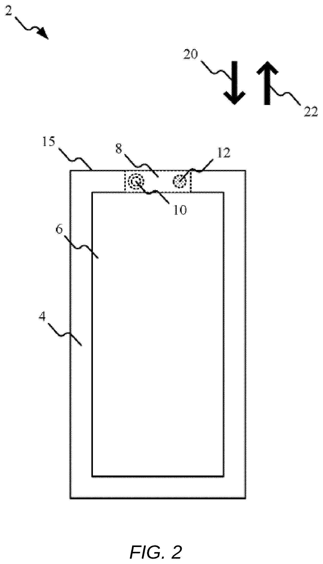
[0009] FIG. 2 is a diagram of the portable electronic device in FIG. 1 with the retractable antenna rod in a retracted position.
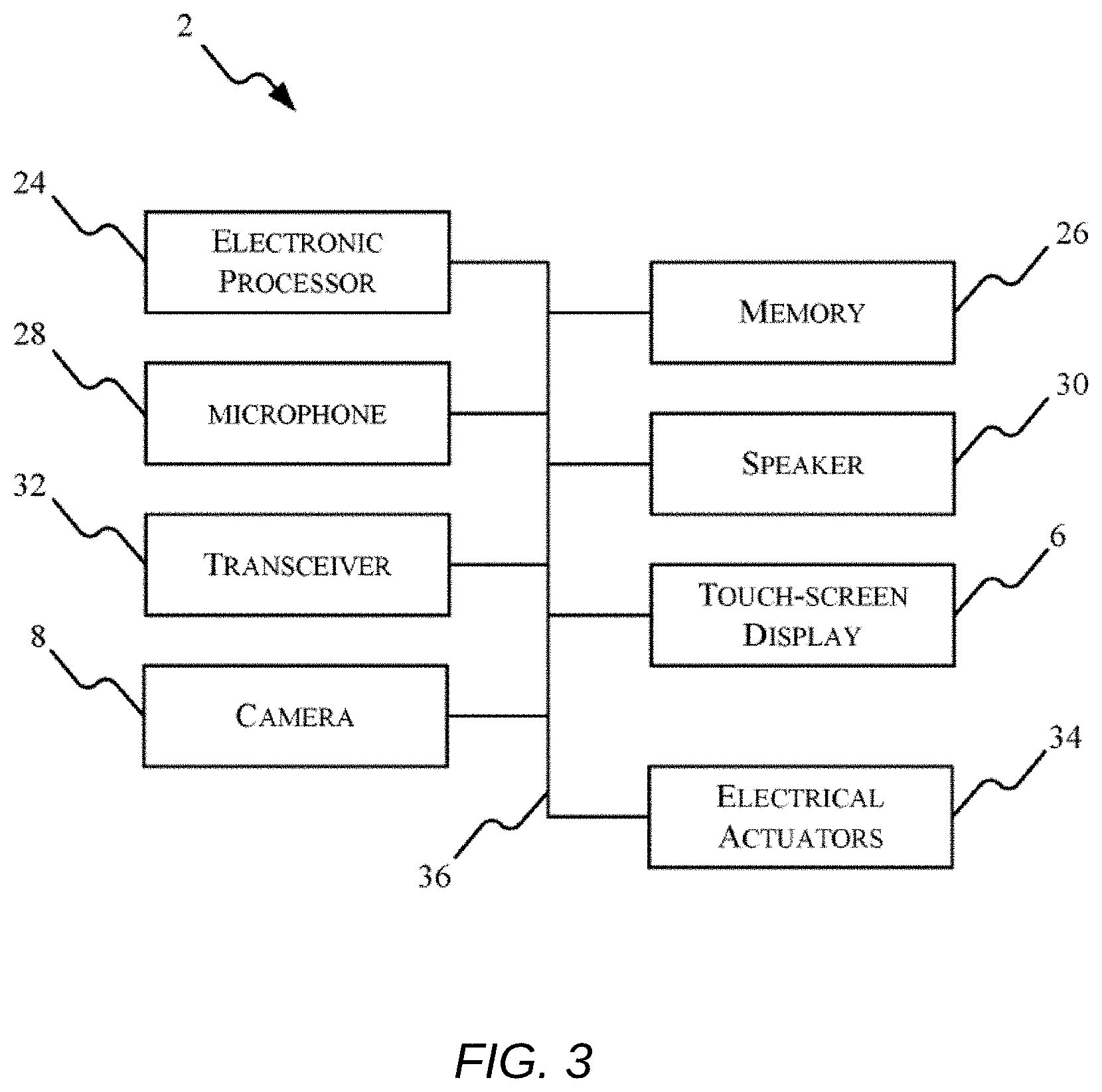
[0010] FIG. 3 is a block diagram of the portable electronic device in FIG. 1, in accordance with some embodiments.
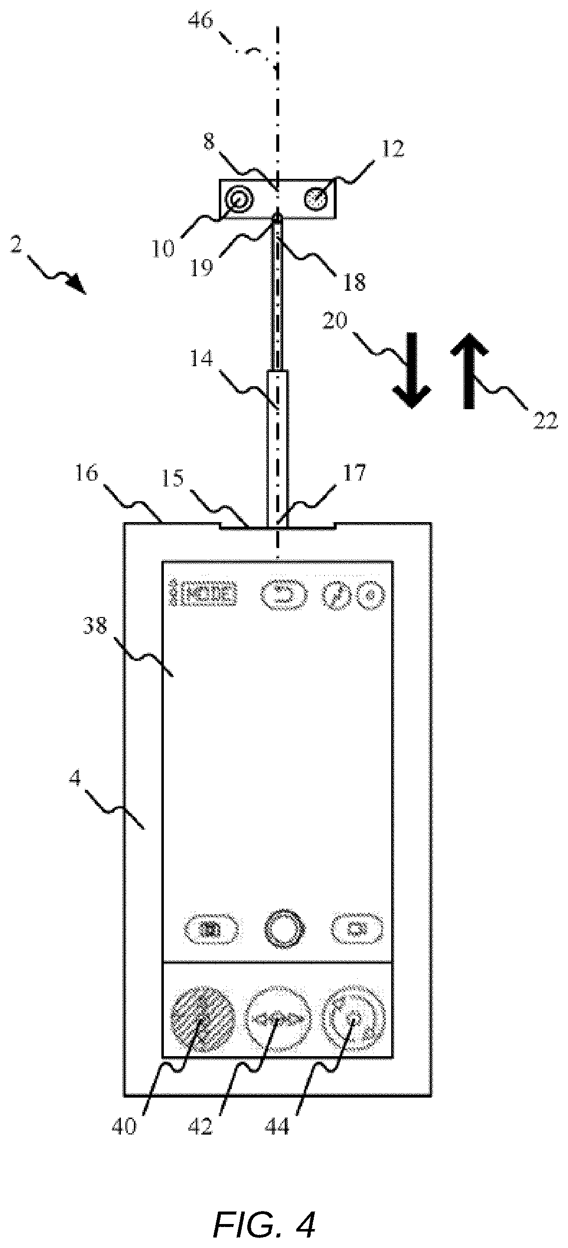
[0011] FIGS. 4, 5, and 6 are exemplary screenshots of a touch-screen display included in the portable electronic device in FIG. 1.
[0012] FIG. 7 illustrates an embodiment of a system with a removable robotic camera module.
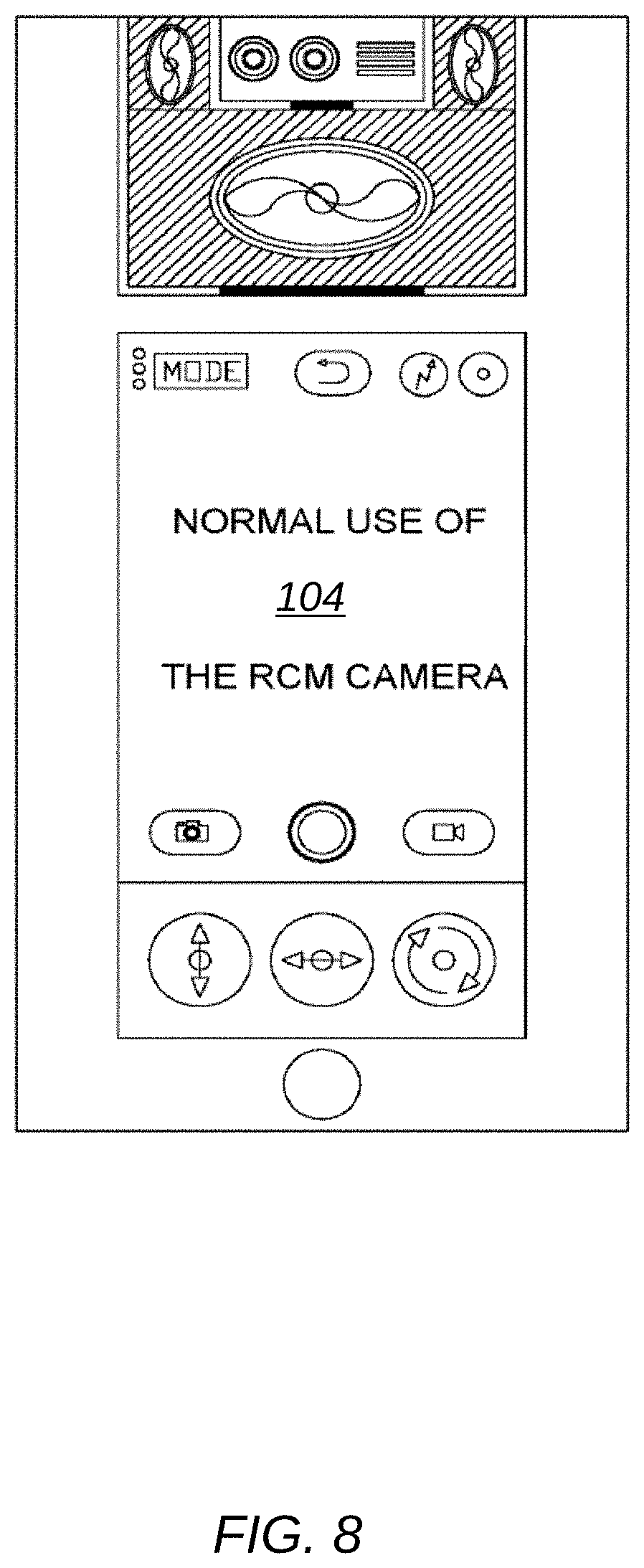
[0013] FIG. 8 illustrates an embodiment of the system with a robotic camera module in home position.
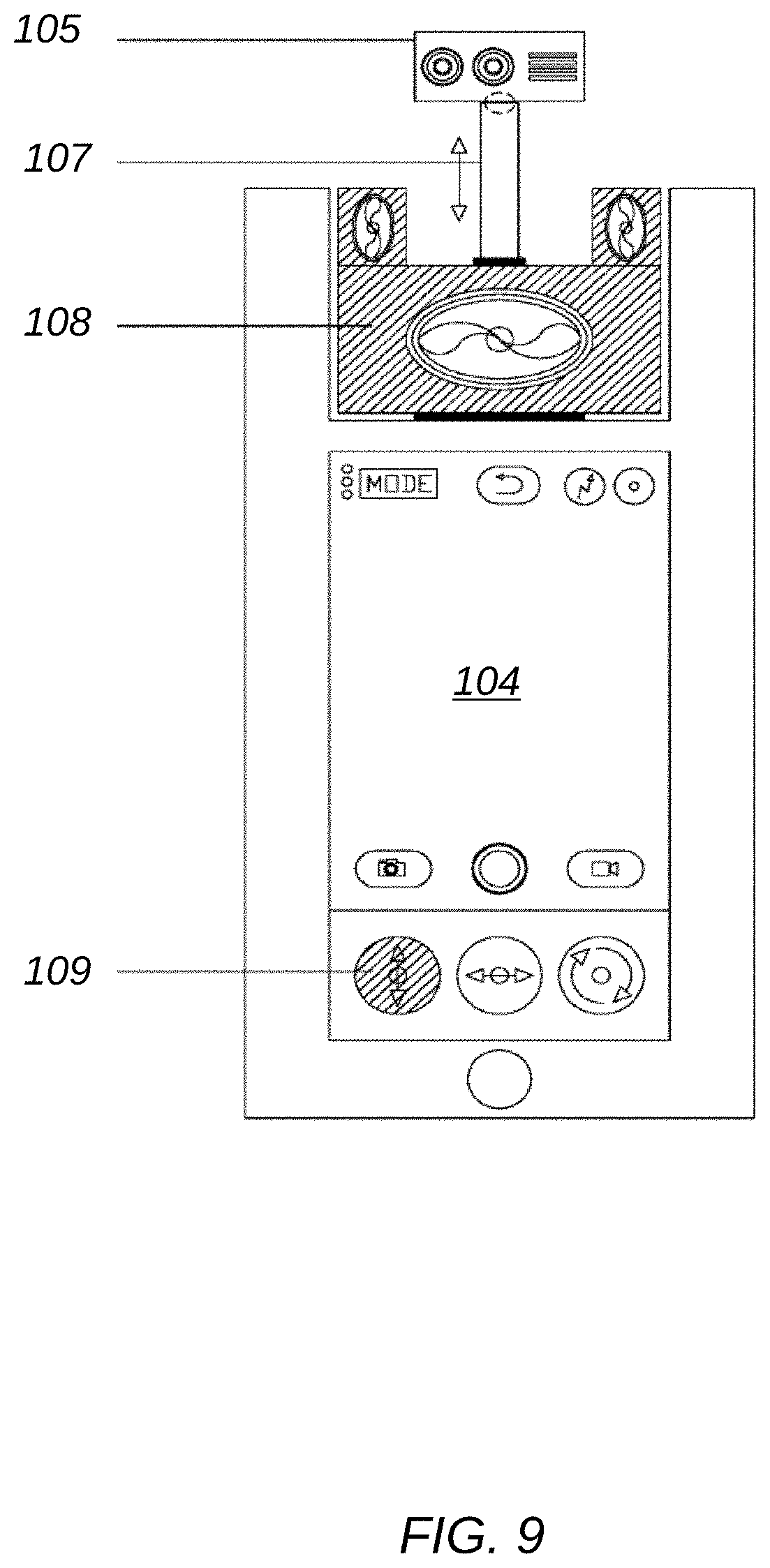
[0014] FIG. 9 illustrates the system with RCM camera lens component on a retractable antenna rod on RCM main body component.
[0015] FIG. 10 illustrates a system with an RCM camera module is a swivel mode.
[0016] FIG. 11 illustrates a system an RCM camera module in a tilt mode.
[0017] FIG. 12 illustrates a system an RCM camera module with an RCM functioning as a micro drone.
DETAILED DESCRIPTION
[0018] For ease of description, each of the exemplary systems presented herein is illustrated with a single exemplar of each of its component parts. Some examples may not describe or illustrate all components of the systems. Other exemplary embodiments may include more or fewer of each of the illustrated components, may combine some components, or may include additional or alternative components.
[0019] FIG. 1 is a diagram of one exemplary embodiment of a portable electronic device 2. In the embodiment illustrated, the portable electronic device 2 is a mobile phone. In other embodiments, the portable electronic device 2 can include other types of devices (for example, tablets, smart terminals, and the like). The portable electronic device 2 in FIG. I includes, among other things, a housing 4, a touch-screen display 6, and a camera 8. The camera 8 includes, among other things, an optical sensor 10 and a light source 12. The camera 8 is coupled to the housing 4 via a retractable antenna rod 14.
[0020] The housing 4 includes an opening 15 at a first end 16 of the housing 4. The retractable antenna rod 14 extends away from the opening 15. The retractable antenna rod 14 includes a first end 17 and a second end 18. The retractable antenna rod 14 is coupled at the first end 17 to a portion of the housing 4 located within the opening 15. The camera 8 is coupled to the second end 18 of the housing 4. In some embodiments, as illustrated in FIG. 1, the camera 8 is coupled to the second end 18 of the housing 4 via a ball bearing connector 19.
[0021] As explained below in more detail, the retractable antenna rod 14 enables movement of the camera 8 relative to the housing 4 (for example, movement in the direction of arrow 20 and 22). FIG. 1 illustrates the camera 8 positioned in an extended position when the camera 8 is positioned outside of and a distance away from the housing 4 in the direction of arrow 22. FIG. 2 illustrates the camera 8 positioned in a retracted position. In the retracted position, the camera 8 (and the retractable antenna rod 14) is positioned within the housing 4.
[0022] FIG. 3 is a diagram of one exemplary embodiment of the portable electronic device 2. In the embodiment illustrated, the portable electronic device 2 includes an electronic processor 24 (for example, a microprocessor, or other electronic controller), a memory 26, a microphone 28, a speaker 30, a transceiver 32, the touch-screen display 6, the camera 8, and electrical actuators 34. The electronic processor 24, the memory 26, as well as the other various modules are coupled by a bus 36, or are coupled directly, by one or more additional control or data buses, or a combination thereof.
[0023] The memory 26 may include read only memory (ROM), random access memory (RAM), other non-transitory computer-readable media, or a combination thereof. The electronic processor 24 is configured to retrieve instructions and data from the memory 26 and execute, among other things, instructions to perform the methods described herein. The microphone 28 captures audio data and the speaker 30 outputs audio data.
[0024] The transceiver 32 is configured to provide communications between the portable electronic device 2 and one or more additional portable electronic devices within a communication system. The transceiver 32 transmits signals to one or more communication networks and receives signals from the communication networks. In some embodiments, signals include, for example, data, audio data, video data, image data, data packets, or any combination thereof. In some embodiments, the transceiver 32 includes a separate transmitter and receiver. The communication network may be implemented using various networks, for example, a cellular network, the Internet, a Bluetooth.TM. network, a wireless local area network (for example, Wi-Fi), a wireless accessory Personal Area Networks (PAN), cable, an Ethernet network, satellite, a machine-to-machine (M2M) autonomous network, and a public switched telephone network.
[0025] The touch-screen display 6 is a touch-sensitive interface that displays visual output, for example, webpages and other graphical user interfaces (GUIs) generated by software applications executed by the electronic processor 24. The touch-screen display 6 also receives user input using detected physical contact, for example, detected capacitance or resistance. Based on the user input, the touch-screen display 6 outputs signals to the electronic processor 24 which indicate positions on the touch-screen display 6 currently being selected by physical contact. In some embodiments, the touch-screen display 6 includes a liquid crystal display (LCD).
[0026] The optical sensor 10 in the camera 8 captures optical signals. For example, the optical sensor 10 may include charged-coupled devices (CCDs) that capture an image, a series of images, video, and the like. The light source 12 includes a light emitting device such as one or more light emitting diodes (LEDs).
[0027] The electrical actuators 34 are operably coupled to the camera 8 and to the retractable antenna rod 14 to cause translational, rotational, and pivotal movements of the camera 8 and the retractable antenna rod 14. Translational, rotational, and pivotal movements of the camera 8 and the retractable antenna rod 14 are explained in more details below. The electrical actuators 34 include, for example, electrical motors. In some embodiments, the portable electronic device 2 includes separate electrical actuators 34 to perform each different type of movement of the camera 8 and the retractable antenna rod 14. For example, a first electrical actuator causes translational movement of the camera 8 and the retractable antenna rod 14 relative to the housing 4, a second electrical actuator causes rotational movement of the camera 8 and the retractable antenna rod 14, and a third electrical actuator causes pivotal movement of the camera 8 relative to the retractable antenna rod 14.
[0028] In some embodiments, the electronic processor 24 controls the movement of the camera 8 and the retractable antenna rod 14 via a graphical user interface (GUI) displayed on the touch-screen display 6. FIGS. 4, 5, and 6 illustrate exemplary screenshots displayed by the touch-screen display 6.
[0029] In FIG. 4, the touch-screen display 6 displays a camera viewing area 38 of the current images captured by the optical sensor 10 in the camera 8. The touch-screen display 6 in FIG. 4 also displays a vertical position control button 40, a horizontal position control button 42, and a tilt position control button 44. In FIG. 4, the vertical position control button 40 is selected. The vertical position control button 40 regulates vertical movement of the camera 8 (for example, movement in the direction of arrow 20 and 22). In other words, translational movement of the camera 8 along a longitudinal axis 45 of the housing 4. When the vertical position control button 40 is selected, the electronic processor 24 receives a signal from the touch-screen display 6 indicating a request from a user to move the camera 8 in the direction of arrow 20 and 22. In response to receiving the signal, the electronic processor 24 sends a signal to the electrical actuators 34 which causes the retractable antenna rod 14 to either retract toward the housing 4 or extend away from the housing 4.
[0030] In FIG. 5, the horizontal position control button 42 is selected. The horizontal position control button 42 regulates horizontal movement of the camera 8 (for example, movement in the direction of arrow 46 and 48). In other words, rotational movement of the camera 8 about the longitudinal axis 45 of the housing 4. When the horizontal position control button 42 is selected, the electronic processor 24 receives a signal from the touch-screen display 6 indicating a request from a user to rotate the camera 8 in the direction of arrow 46 and 48. In response to receiving the signal, the electronic processor 24 sends a signal to the electrical actuators 34 which causes the retractable antenna rod 14 (and the camera 8) to rotate.
[0031] In some embodiments, the electronic processor 24 continuously rotates the camera 8 as long as the horizontal position control button 42 remains selected. In other embodiments, the electronic processor 24 rotates the camera 8 by a set amount each time the horizontal position control button 42 is selected. For example, in some embodiments, the electronic processor 24 rotates the camera 8 by 180 degrees each time the horizontal position control button 42 is selected. By having the camera 8 rotate, the portable electronic device 2 can captures images on multiple sides of the housing 4 with a single camera.
[0032] In FIG. 6, the tilt position control button 44 is selected. The tilt position control button 44 regulates tilting movements of the camera 8 (for example, movement in the direction of arrow 50 and 52). In other words, pivotal movement of the camera 8 with respect to (or relative to) the longitudinal axis 45 of the housing 4. When the tilt position control button 44 is selected, the electronic processor 24 receives a signal from the touch-screen display 6 indicating a request from a user to pivot the camera 8 in the direction of arrow 50 and 52. In response to receiving the signal, the electronic processor 24 sends a signal to the electrical actuators 34 which causes the camera 8 to pivot relative to the second end 18 of the retractable antenna rod 14.
[0033] In an embodiment, a smart terminal is equipped with a removable robot. In certain embodiments, built-in sensors of a smart terminals are replaced with removable intelligent multifunctional robotic modules.
[0034] In an embodiment, a smart terminal is equipped with removable robots, to improve their technology and to increase their value, freedom, efficiency and convenience by replacing their built-in unintelligent sensors with removable intelligent Robotic Modules. For example, integrating within the ST a removable micro hovering drone--a Robotic Camera Module (RCM)--to replace the built-in image sensors. The RCM's Rotating Telescopic Retractable Antenna Rod allows the attached camera lens to extend out of and beyond the frame of the ST, then to swivel and tilt to capture fixed or 360-degree panoramic images along all 3 axes (radar-like), for greater flexibility, stealth, quality, and clarity (no flipping selfies). Remove the RCM from its docking station, pair it with its host ST, and turn the latter into an augmented-reality viewfinder.
[0035] Embodiments may include every field of current and future robotics applications, including technology, IOT, health care, education, medical, security, household appliances, construction, communication, gaming, drones etc. For an illustrative example, systems, methods and devices are described herein that integrate a smart terminal and a removable micro hovering drone--a Robotic Camera Module (RCM)--equipped with multi-sensors and technological devices, and a power and communication docking port to replace the current built-in image sensors.
[0036] FIG. 7 illustrates an embodiment of a system with a removable robotic camera module. The system includes robotic camera module 101, terminal 102, and power & communication docking port 103, and smart terminal 104.
[0037] FIG. 8 illustrates an embodiment of the system with a robotic camera module in home position. In normal (home) position, the RCM 101 is seamlessly located within its host smart terminal 104, connected to the ST's docking station 103), with the top portion of the camera lens component flush within the ST's frame. When the camera application is activated, images are captured in customary point and shoot mode using the RCM's camera.
[0038] The RCM is also equipped with a Rotating Telescopic Retractable Antenna Rod (RTRA) 107 attached to the main body 108 of the RTRA on one end, and to the camera lens component 105 (via a ball bearing connector (D) on the other, allowing the camera lens to extend out of and beyond the frame of the ST, then rotate (swivel) and tilt - much like the movement of a high technology radar to capture images along all 3 axes within a 360-degree spectrum.
[0039] FIG. 9 illustrates the system with RCM camera lens component 105 on retractable antenna rod 107 on RCM main body component 108. The Vertical position control Function 109 is used to lift the RTRA and camera lens up to several inches past the smart terminal frame.
[0040] FIG. 10 illustrates a system with an RCM camera module is a swivel mode. Once the bottom of the camera lens component clears the ST's frame and reaches its desired height, the Horizontal position control Function 110 is activated to radially rotate (swivel) the RTRA to any angle, such that the sensors can capture fixed or panoramic images along the 360-degree horizontal plane.
[0041] For example, flat frontal and back facing images (normal use and selfies, respectively) would have the camera lens parallel to the plane of the ST's frame, while right and left flat position images would have the camera lens perpendicular to the plane of the ST's frame.
[0042] As shown in FIG. 11, in combination with the aforementioned Vertical and Horizontal position functions, the Tilt position control Function 111, which controls the ball-bearing connector 106 at the camera lens end of the RTRA, allows the camera lens 105 to additionally capture angular tilt images, for the ultimate in flexibility and coverage along all 3 axes within a 360-degree spectrum.
[0043] These functions, separately or in combination, all provide for a greater image selection spectrum, flexibility, stealth, quality (HD/DSLR), and clarity (no more flipping images on selfies). When the RCM 101 is removed from its docking station within its host ST 104, it now functions as an autonomous hovering micro drone, which, when paired with its host ST, turns the latter into a remote control 112 with an augmented-reality viewfinder 113.
[0044] This disclosure is not limited in its application to the examples provided, the embodiments discussed, or to the details of construction and the arrangement of components set forth in the foregoing description or drawings. The disclosure is capable of other embodiments and of being practiced or of being carried out in various ways.
* * * * *
D00000
D00001
D00002
D00003
D00004
D00005
D00006
D00007
D00008
D00009
D00010
D00011
D00012

XML
uspto.report is an independent third-party trademark research tool that is not affiliated, endorsed, or sponsored by the United States Patent and Trademark Office (USPTO) or any other governmental organization. The information provided by uspto.report is based on publicly available data at the time of writing and is intended for informational purposes only.
While we strive to provide accurate and up-to-date information, we do not guarantee the accuracy, completeness, reliability, or suitability of the information displayed on this site. The use of this site is at your own risk. Any reliance you place on such information is therefore strictly at your own risk.
All official trademark data, including owner information, should be verified by visiting the official USPTO website at www.uspto.gov. This site is not intended to replace professional legal advice and should not be used as a substitute for consulting with a legal professional who is knowledgeable about trademark law.