Round Metal Pipe, Heat Exchanger Provided With Same, Pipe Bender, And Method For Bend-processing Round Metal Pipe
SE; Naoki ; et al.
U.S. patent application number 16/933732 was filed with the patent office on 2020-11-05 for round metal pipe, heat exchanger provided with same, pipe bender, and method for bend-processing round metal pipe. This patent application is currently assigned to NORITZ CORPORATION. The applicant listed for this patent is NORITZ CORPORATION. Invention is credited to Hideyuki FUJISAWA, Shoji OKUDA, Naoki SE.
| Application Number | 20200348085 16/933732 |
| Document ID | / |
| Family ID | 1000004973732 |
| Filed Date | 2020-11-05 |


| United States Patent Application | 20200348085 |
| Kind Code | A1 |
| SE; Naoki ; et al. | November 5, 2020 |
ROUND METAL PIPE, HEAT EXCHANGER PROVIDED WITH SAME, PIPE BENDER, AND METHOD FOR BEND-PROCESSING ROUND METAL PIPE
Abstract
A round metal pipe 1 including a bend portion 10 is configured such that on an axial direction cross-section of the bend portion 10, an outer half portion 11b of a peripheral wall portion 11 of the bend portion 10 has an outwardly projecting, non-circular arc shape in which a central portion in a y direction, which is orthogonal to a bend radius direction x of the bend portion 10, forms an outermost peripheral portion 13, and a distance Lb from respective intermediate portions 15 between the outermost peripheral portion 13 and a pair of proximal end portions 14 of the outer half portion 11b to a pipe center O is shorter than a distance La from the outermost peripheral portion 13 to the pipe center O. Thus, advantages such as suppressing reductions in the sectional area and minimum inside width of the bend portion 10 and reducing flow path resistance can be obtained, and the round metal pipe 1 can be manufactured easily and appropriately.
| Inventors: | SE; Naoki; (Kobe-shi, JP) ; OKUDA; Shoji; (Kobe-shi, JP) ; FUJISAWA; Hideyuki; (Kobe-shi, JP) | ||||||||||
| Applicant: |
|
||||||||||
|---|---|---|---|---|---|---|---|---|---|---|---|
| Assignee: | NORITZ CORPORATION Hyogo JP |
||||||||||
| Family ID: | 1000004973732 | ||||||||||
| Appl. No.: | 16/933732 | ||||||||||
| Filed: | July 20, 2020 |
Related U.S. Patent Documents
| Application Number | Filing Date | Patent Number | ||
|---|---|---|---|---|
| PCT/JP2019/001777 | Jan 22, 2019 | |||
| 16933732 | ||||
| Current U.S. Class: | 1/1 |
| Current CPC Class: | B21D 9/14 20130101; F28D 7/082 20130101; F28F 2255/00 20130101; F28F 1/06 20130101; B21D 53/06 20130101; B21D 9/073 20130101 |
| International Class: | F28D 7/08 20060101 F28D007/08; F28F 1/06 20060101 F28F001/06; B21D 9/07 20060101 B21D009/07; B21D 9/14 20060101 B21D009/14; B21D 53/06 20060101 B21D053/06 |
Foreign Application Data
| Date | Code | Application Number |
|---|---|---|
| Jan 26, 2018 | JP | 2018-011256 |
Claims
1. A round metal pipe including a bend portion, wherein, on an axial direction cross-section of the bend portion, an outer half portion of a peripheral wall portion of the bend portion has an outwardly projecting, non-circular arc shape in which a central portion in an orthogonal direction to a bend radius direction of the bend portion forms an outermost peripheral portion, and a distance from respective intermediate portions between the outermost peripheral portion and a pair of proximal end portions of the outer half portion to a pipe center is shorter than a distance from the outermost peripheral portion to the pipe center.
2. The round metal pipe according to claim 1, wherein, on the axial direction cross-section of the bend portion, an inner half portion of the peripheral wall portion of the bend portion has either a semicircular arc shape or a shape that is closer to a semicircular arc shape than the outer half portion.
3. The round metal pipe according to claim 1, wherein, on the axial direction cross-section of the bend portion, the outermost peripheral portion and the intermediate portions of the outer half portion are respectively formed in either an outwardly projecting curved shape or a straight shape such that no inwardly depressed parts are provided on the outer half portion.
4. A heat exchanger comprising a heat transfer pipe, wherein the heat transfer pipe is constructed using the round metal pipe according to claim 1.
5. The heat exchanger according to claim 4, wherein the heat transfer pipe is a meandering heat transfer pipe in which a plurality of bend portions are provided as the bend portion and a plurality of straight pipe body portions arranged via intervals in a direction intersecting an axial length direction are connected in series via the plurality of bend portions.
6. A pipe bender comprising: a rolling block having a first pipe insertion recess, into which a bending direction inner surface side of a round metal pipe is to be inserted, formed in an outer peripheral surface thereof; and a pressure die having a second pipe insertion recess, into which a bending direction outer surface side of the round metal pipe is to be inserted, formed in a side face thereof, wherein a bend portion is formable on the round metal pipe by clamping the round metal pipe between respective inner surfaces of the first and second pipe insertion recesses, and the second pipe insertion recess has a non-semicircular cross-section on which a central portion in an opening width direction of the second pipe insertion recess forms a deepest portion, and a distance from respective intermediate portions between the deepest portion and a pair of edge portions of the second pipe insertion recess to a center between the pair of edge portions is shorter than a distance from the deepest portion to the center.
7. The pipe bender according to claim 6, wherein the first pipe insertion recess is formed to have either a semicircular sectional shape or a sectional shape that is closer to a semicircular shape than the second pipe insertion recess.
8. The pipe bender according to claim 6, wherein the deepest portion and the intermediate portions of the second pipe insertion recess are formed to have either a recessed, curved sectional shape or a straight sectional shape such that no projecting parts are provided on the second pipe insertion recess.
9. A method for bend-processing a round metal pipe, comprising the step of: using a pipe bender including a rolling block having a first pipe insertion recess formed in an outer peripheral surface thereof and a pressure die having a second pipe insertion recess formed in a side face thereof to bend the round metal pipe by clamping the round metal pipe between respective inner surfaces of the first and second pipe insertion recesses, wherein the pipe bender according to claim 6 is used as the pipe bender.
Description
TECHNICAL FIELD
[0001] The present invention relates to a round metal pipe formed with a bend portion, and techniques relating thereto.
BACKGROUND ART
[0002] A round metal pipe including a bend portion, such as a heat transfer pipe with a U shape, a meandering shape, or a spiral shape, is often used as a heat transfer pipe of a heat exchanger. A round metal pipe including a bend portion of this type is manufactured by bend-processing a straight pipe-shaped round metal pipe using a pipe bender (see PTL 1 and PTL 2, for example).
[0003] A pipe bender shown as an example in FIG. 6 includes a rolling block 2 and a pressure die 3. Semicircular first and second pipe insertion recesses 21, 31 are provided respectively in the rolling block 2 and the pressure die 3. To form a bend portion in a round metal pipe 1, the round metal pipe 1 is bent around the first pipe insertion recess 21 of the rolling block 2 while clamped between respective inner surfaces of the first and second pipe insertion recesses 21, 31.
[0004] According to the means described above, the round metal pipe 1 having a bend portion 10, as shown in FIG. 7, is obtained. The bend portion 10 of the round metal pipe 1 is formed such that an inner half portion 11a on the inside of a center line C1 takes the shape of a semicircular arc, while a large region of an outer half portion 11b on the outside of the center line C1 is depressed toward the center line C1. Of the outer half portion 11b, a part Pa that originally formed the outermost portion is offset toward the center line C1 by an appropriate dimension Lc.
[0005] When forming the bend portion 10, the inner half portion 11a serves as a compressed side, while the outer half portion 11b serves as a pulled side. Accordingly, as a curvature radius R (a bend radius) of the bend portion 10 decreases, an amount of tensile deformation applied to the outer half portion 11b increases, leading to an increase in the aforementioned dimension Lc, and as a result, the outer half portion 11b is flattened. Moreover, when the bend-processing speed of the round metal pipe 1 is increased, this flattening becomes more noticeable.
[0006] With the prior art described above, however, there remains room for improvement, as described below.
[0007] Firstly, when the bend portion 10 is flattened into the form described above, the sectional area of the bend portion 10 becomes considerably smaller than the original sectional area prior to bend-processing. A minimum inside width Ld of the bend portion 10 also decreases. As a result, flow path resistance increases when a fluid is passed through the round metal pipe 1. This is undesirable in a case where the round metal pipe 1 is used as a heat transfer pipe of a heat exchanger or the like, for example.
[0008] Secondly, flattening of the bend portion 10 becomes steadily more noticeable as the bend-processing speed of the round metal pipe 1 is increased. Hence, in order to suppress flattening of the bend portion 10, it is necessary to reduce the bend-processing speed, but in so doing, productivity deteriorates.
[0009] Conventionally, meanwhile, as described in PTL 3, for example, means for preventing flattening of the bend portion by disposing a metal core inside of the bend-processing target part may be employed when implementing bend-processing on the round metal pipe. By employing this means, however, increases occur in operational complexity and facility costs. Moreover, when the overall length of the round metal pipe is comparatively large, or when a plurality of bend portions are to be provided on a single round metal pipe, the metal core cannot be disposed and accommodated inside the bend-processing target part, making it difficult to perform bend-processing using the metal core. Hence, it remains difficult to appropriately solve the problems described above.
CITATION LIST
Patent Literature
[0010] [PTL 1] Japanese Patent Application Publication No. 2016-131977
[0011] [PTL 2] Japanese Patent Application Publication No. 2012-135797
[0012] [PTL 3] Japanese Patent Application Publication No. 2004-322186
SUMMARY OF INVENTION
Technical Problem
[0013] An object of the present invention is to provide a round metal pipe, a heat exchanger including the round metal pipe, a pipe bender suitable for manufacturing the round metal pipe, and a method for bend-processing the round metal pipe with which problems such as those described above can be solved appropriately.
Solution to Problem
[0014] To achieve the object described above, the present invention teaches the following technical means.
[0015] A round metal pipe provided by a first aspect of the present invention includes a bend portion, wherein, on an axial direction cross-section of the bend portion, an outer half portion of a peripheral wall portion of the bend portion has an outwardly projecting, non-circular arc shape in which a central portion in an orthogonal direction to a bend radius direction of the bend portion forms an outermost peripheral portion, and a distance from respective intermediate portions between the outermost peripheral portion and a pair of proximal end portions of the outer half portion to a pipe center is shorter than a distance from the outermost peripheral portion to the pipe center.
[0016] Preferably, on the axial direction cross-section of the bend portion, an inner half portion of the peripheral wall portion of the bend portion has either a semicircular arc shape or a shape that is closer to a semicircular arc shape than the outer half portion.
[0017] Preferably, on the axial direction cross-section of the bend portion, the outermost peripheral portion and the intermediate portions of the outer half portion are respectively formed in either an outwardly projecting curved shape or a straight shape such that no inwardly depressed parts are provided on the outer half portion.
[0018] A heat exchanger provided by a second aspect of the present invention includes a heat transfer pipe, and the heat transfer pipe is constructed using the round metal pipe provided by the first aspect of the present invention.
[0019] Preferably, the heat transfer pipe is a meandering heat transfer pipe in which a plurality of bend portions are provided as the bend portion and a plurality of straight pipe body portions arranged via intervals in a direction intersecting an axial length direction are connected in series via the plurality of bend portions.
[0020] A pipe bender provided by a third aspect of the present invention includes a rolling block having a first pipe insertion recess, into which a bending direction inner surface side of a round metal pipe is inserted, formed in an outer peripheral surface thereof, and a pressure die having a second pipe insertion recess, into which a bending direction outer surface side of the round metal pipe is inserted, formed in a side face thereof, wherein a bend portion can be formed on the round metal pipe by clamping the round metal pipe between respective inner surfaces of the first and second pipe insertion recesses, and the second pipe insertion recess has a non-semicircular cross-section on which a central portion in an opening width direction of the second pipe insertion recess forms a deepest portion, and a distance from respective intermediate portions between the deepest portion and a pair of edge portions of the second pipe insertion recess to a center between the pair of edge portions is shorter than a distance from the deepest portion to the center.
[0021] Preferably, the first pipe insertion recess is formed to have either a semicircular sectional shape or a sectional shape that is closer to a semicircular shape than the second pipe insertion recess.
[0022] Preferably, the deepest portion and the intermediate portions of the second pipe insertion recess are formed to have either a recessed, curved sectional shape or a straight sectional shape such that no projecting parts are provided on the second pipe insertion recess.
[0023] A method for bend-processing a round metal pipe provided by a fourth aspect of the present invention includes a step of using a pipe bender that includes a rolling block having a first pipe insertion recess formed in an outer peripheral surface thereof and a pressure die having a second pipe insertion recess formed in a side face thereof to bend the round metal pipe by clamping the round metal pipe between respective inner surfaces of the first and second pipe insertion recesses, wherein the pipe bender provided by the third aspect of the present invention is used as the pipe bender.
[0024] Other features and advantages of the present invention will become more apparent from the embodiment of the invention that is described below with reference to the figures.
BRIEF DESCRIPTION OF DRAWINGS
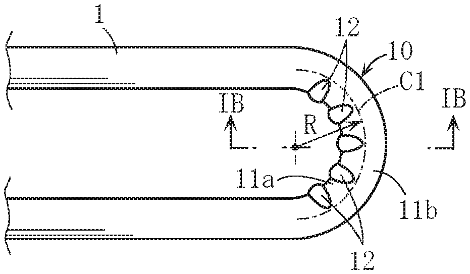
[0025] FIG. 1A is a plan view showing main parts of an example of a round metal pipe according to the present invention, and FIG. 1B is an IB-IB enlarged sectional view of FIG. 1A.
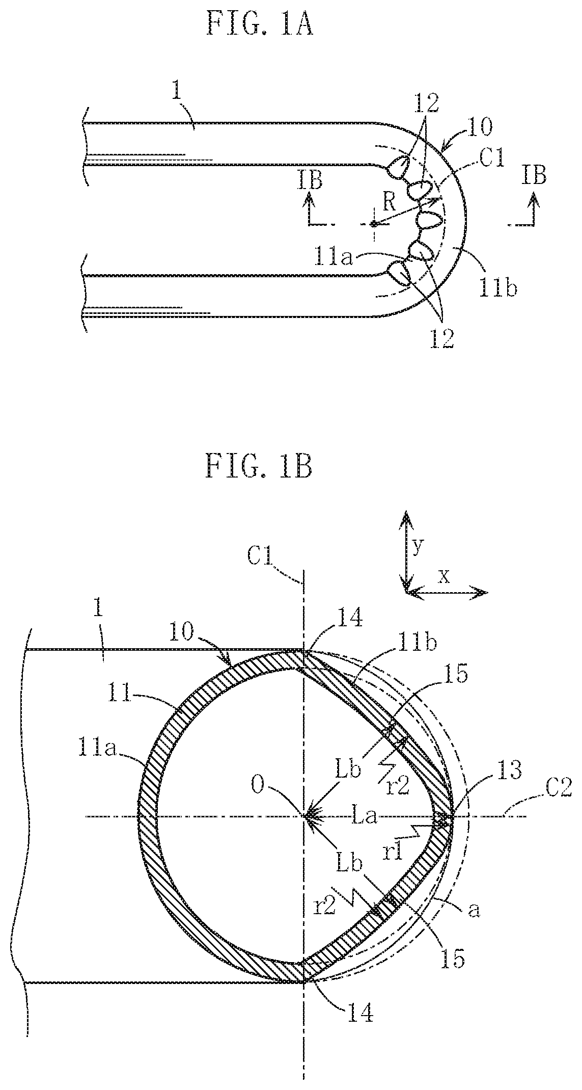
[0026] FIG. 2A is a schematic planar sectional view showing an example of a pipe bender according to the present invention, FIG. 2B is an IIB-IIB sectional view of FIG. 2A, and FIG. 2C is an IIC-IIC sectional view of FIG. 2A.
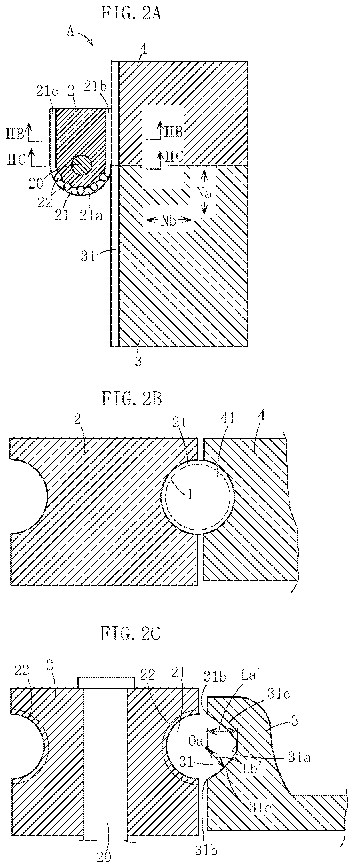
[0027] FIG. 3A is a schematic planar sectional view of a state in which the round metal pipe is set in the pipe bender shown in FIGS. 2A to 2C, and FIG. 3B is an IIIB-IIIB sectional view of FIG. 3A.
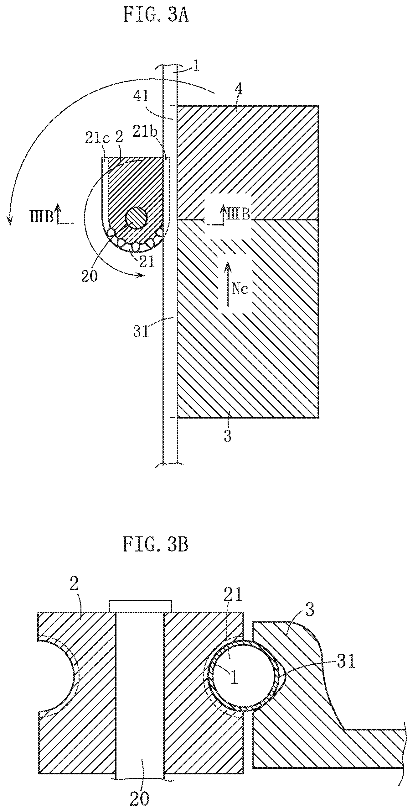
[0028] FIG. 4 is a schematic planar sectional view of a state in which a bend portion has been formed on the round metal pipe by operating the pipe bender from the state shown in FIGS. 3A and 3B.
[0029] FIG. 5A is a planar sectional view showing an example of a heat exchanger constructed using a round metal pipe having a bend portion, FIG. 5B is a VB-VB sectional view of FIG. 5A, and FIG. 5C is a side view.
[0030] FIG. 6 is a sectional view showing main parts of an example of a pipe bender according to the prior art.
[0031] FIG. 7A is a planar view showing main parts of an example of a round metal pipe according to the prior art, and FIG. 7B is a VIIB-VIIB enlarged sectional view of FIG. 7A.
DESCRIPTION OF EMBODIMENTS
[0032] A preferred embodiment of the present invention will be described specifically below with reference to the figures.
[0033] Elements that are identical or similar to the prior art shown in FIGS. 6, 7A and 7B have been allocated identical reference numerals to those of the prior art as appropriate.
[0034] A round metal pipe 1 shown in FIG. 1A is made of stainless steel, for example, and includes a bend portion 10 that curves by an appropriate curvature radius R over an angle range of 180.degree.. As shown in FIG. 1B, on an axial direction cross-section of the bend portion 10, an inner half portion 11a (on the inside (the left side) of a center line C1) of a peripheral wall portion 11 of the bend portion 10 takes the shape of a semicircular arc. Note, however, that the inner half portion 11a is a site where the peripheral wall portion 11 is compressed in a circumferential direction, and therefore, as shown in FIG. 1A, the inner half portion 11a is formed in a wrinkled shape having a plurality of projecting portions 12.
[0035] Meanwhile, an outer half portion 11b (on the outside of the center line C1) of the peripheral wall portion 11 of the bend portion 10 takes the shape of an outwardly projecting, non-circular arc. More specifically, a central portion (a part through which a center line C2 passes) of the outer half portion 11b in a y direction of FIG. 1B (an up-down vertical direction in the figure) serves as an outermost peripheral portion 13. The y direction is an orthogonal direction to an x direction, which is a bend radius direction of the bend portion 10 (the same direction as a direction in which an inner peripheral portion and an outer peripheral portion of the bend portion 10 oppose each other, i.e. a left-right direction in FIG. 1B). Here, a distance Lb from a pair of intermediate portions 15 to a pipe center O is set to be shorter than a distance La from the outermost peripheral portion 13 to the pipe center O (a relationship of La>Lb). The intermediate portions 15 are sites respectively located between the outermost peripheral portion 13 and a pair of proximal end portions 14 of the outer half portion 11b. The pair of proximal end portions 14 are sites serving as proximal ends of the outer half portion 11b, and are the sites of the outer half portion 11b that are closest to the center line C1.
[0036] As a result of the bend-processing applied to the round metal pipe 1, to be described below, the position of the outermost peripheral portion 13 may deviate slightly from the original position thereof prior to bend-processing toward the pipe center O. Accordingly, a distance from the part of the intermediate portion 15 closest to the proximal end portion 14 to the pipe center O may become longer than the distance La. In the present invention, however, it is not necessary for the entire region of the intermediate portion 15 to satisfy the relationship of La>Lb as long as the distance Lb from at least a part of the intermediate portion 15 (for example, a central portion of the intermediate portion 15 or the vicinity thereof) to the pipe center O satisfies the relationship of La>Lb.
[0037] This point applies likewise to a relationship between distances La', Lb' relating to a deepest portion 31a and intermediate portions 31c of a second pipe insertion recess 31 of a pressure die 3 to be described below.
[0038] Considered from a different perspective, the outer half portion 11b corresponds to a form in which the intermediate portions 15 are positioned closer to the pipe center O than an arc a passing through three points on the pair of proximal end portions 14 and the outermost peripheral portion 13.
[0039] On the axial direction cross-section of the bend portion 10, no inwardly depressed parts are provided on the outer half portion 11b, and the outermost peripheral portion 13 and intermediate portions 15 all have an outwardly projecting curved shape. Respective curvature radii r1, r2 thereof differ from each other such that r1<r2, for example. Note, however, that the present invention is not limited thereto, and instead, the outermost peripheral portion 13 and/or the intermediate portions 15 may be formed in a non-curved shape (a straight shape), for example.
[0040] Next, an example of a pipe bender A for forming the bend portion 10 and an example of a method for forming the bend portion 10 using the pipe bender A will be described.
[0041] The pipe bender A shown in FIGS. 2A to 2C includes a rolling block 2, the pressure die 3, and a clamping die 4.
[0042] The rolling block 2 is capable of rotating horizontally about a shaft portion 20, and a first pipe insertion recess 21 is formed continuously in an outer peripheral surface thereof. On a planar cross-section, the first pipe insertion recess 21 includes a curved portion 21a curved into an arc shape over an angle range of 180.degree., and rectilinear portions 21b, 21c connected to respective ends of the curved portion 21a. The first pipe insertion recess 21 has a form that corresponds to the inner half portion 11a of the bend portion 10 described above. More specifically, as shown in FIG. 2C, the first pipe insertion recess 21 has a semicircular sectional shape (a semicircular arc-shaped inner surface). Note, however, that a plurality of recessed groove portions 22 having a greater depth than the first pipe insertion recess 21 are provided at appropriate intervals in the inner surface of the first pipe insertion recess 21. The recessed groove portions 22 are sites corresponding to the projecting portions 12 shown in FIG. 1A.
[0043] The pressure die 3 is a block-shaped member in which the second pipe insertion recess 31 is formed continuously in a horizontal direction, indicated by an arrow Na, in a side face thereof. The pressure die 3 is capable of reciprocating in the direction of the arrow Na when positioned beside the rolling block 2, and is also capable of reciprocating in a horizontal direction indicated by an arrow Nb, which intersects the direction of the arrow Na, so as to approach and separate from the rolling block 2.
[0044] The second pipe insertion recess 31 has a form that corresponds to the outer half portion 11b of the bend portion 10 described above. More specifically, as shown in FIG. 2C, the second pipe insertion recess 31 has a non-semicircular sectional shape in which a central portion in an up-down opening width direction serves as the deepest portion 31a, and the distance Lb' from each of the pair of intermediate portions 31c to a center Oa between a pair of edge portions 31b of the second pipe insertion recess 31 is shorter than the distance La' from the deepest portion 31a to the center Oa. The intermediate portions 31c are sites between the deepest portion 31a and the respective edge portions 31b. The deepest portion 31a and the intermediate portions 31c are sites corresponding respectively to the outermost peripheral portion 13 and the intermediate portions 15 of the bend portion 10 shown in FIG. 1B, and are preferably formed to have a recessed, curved sectional shape or a non-curved (straight) sectional shape such that no projecting parts are provided on the second pipe insertion recess 31.
[0045] The clamping die 4 is a site for clamping the round metal pipe 1 together with the rolling block 2 so as to exert a pulling action on the round metal pipe 1. A third pipe insertion recess 41 having a semicircular cross-section, as shown in FIG. 2B, is provided in a side face of the clamping die 4. The clamping die 4 is configured such that when the rolling block 2 is rotated about the shaft portion 20, the clamping die 4 rotates horizontally about the shaft portion 20 together therewith. Thus, deviation can be prevented from occurring in the relative positional relationship between the clamping die 4 and the rolling block 2, and as a result, the round metal pipe 1 can be kept in a clamped state by both the rolling block 2 and the clamping die 4.
[0046] Processing for forming the bend portion 10 on the round metal pipe 1 using the pipe bender A described above is performed as follows.
[0047] First, as shown in FIGS. 3A and 3B, the round metal pipe 1 is set such that a bending direction inner surface side is inserted into the first pipe insertion recess 21 (the rectilinear portion 21b) of the rolling block 2 and a bending direction outer surface side is inserted into the second and third pipe insertion recesses 31, 41 of the pressure die 3 and the clamping die 4. The pressure die 3 and the clamping die 4 are then brought closer to the rolling block 2 side so as to clamp the round metal pipe 1 with enough force to ensure that no slippage or the like occurs between the round metal pipe 1 and the pressure die 3 and clamping die 4.
[0048] Next, in the set state described above, the rolling block 2 and the clamping die 4 are rotated 180.degree. horizontally about the shaft portion 20. As a result, as shown in FIG. 4, a part of the round metal pipe 1 is bent around the curved portion 21a of the first pipe insertion recess 21 of the rolling block 2, thereby forming the bend portion 10. The bend portion 10 has a similar configuration to that described with reference to FIGS. 1A and 1B.
[0049] Hence, with the bend-processing method using the pipe bender A, as described above, the round metal pipe 1 including the bend portion 10 can be manufactured easily and appropriately. Note that by causing the pressure die 3 to advance in the direction of an arrow Nc while the rolling block 2 and clamping die 4 rotate as described above, it is possible to adjust the tensile force, or the amount of pulling, applied to the outer half portion 11b of the bend portion 10.
[0050] FIGS. 5A to 5C show an example of a heat exchanger HE. A plurality of heat transfer pipes 1A of the heat exchanger HE are formed from heat transfer pipes having an overall meandering shape by forming the bend portion 10 described above in a plurality of locations on the round metal pipe 1. More specifically, each heat transfer pipe 1A includes the plurality of bend portions 10 and a plurality of straight pipe body portions 18 arranged via intervals in a direction intersecting an axial length direction, the plurality of straight pipe body portions 18 being connected in series by the plurality of bend portions 10.
[0051] In the heat exchanger HE, the plurality of heat transfer pipes 1A are housed in a case 5 so as to be stacked via intervals in an up-down height direction. An intake port 50 and an exhaust port 51 for combustion gas serving as heating gas are provided in the case 5. Further, respective end portions of each heat transfer pipe 1A are disposed inside cold water inlet and hot water outlet headers 6a, 6b such that water to be heated, supplied through a cold water inlet 60a of the header 6a, is heated while passing through the respective heat transfer pipes 1A, then enters the header 6b, and is then discharged as hot water through a hot water outlet 60b.
[0052] Next, actions of the round metal pipe 1 shown in FIGS. 1A and 1B will be described.
[0053] Firstly, in the bend portion 10, the inner half portion 11a is, as expected, not flattened, and moreover, the outer half portion 11b is also not greatly flattened. Hence, in comparison with the prior art shown in FIGS. 7A and 7B, the sectional area and minimum inside width of the bend portion 10 can be increased. As a result, the flow path resistance that occurs when a fluid is passed through the round metal pipe 1 can be reduced. This is desirable for reducing water flow resistance of the heat transfer pipes 1A in the heat exchanger HE shown in FIGS. 5A to 5C.
[0054] In the outer half portion 11b of the bend portion 10, the intermediate portions 15 are positioned closer to the pipe center O than the outermost peripheral portion 13. With this form, the intermediate portions 15 serve as the sites that are depressed (displaced toward the pipe center O) when the outer half portion 11b of the bend portion 10 is pulled and stretched during molding of the bend portion 10. Thus, the outermost peripheral portion 13 of the outer half portion 11b can be formed so as not to be greatly depressed toward the pipe center O. Therefore, even when the bend-processing speed of the round metal pipe 1 is set to be comparatively high, flattening of the bend portion 10 can be avoided appropriately, which is desirable for improving the productivity and reducing the manufacturing cost of the round metal pipe 1 including the bend portion 10.
[0055] In this embodiment, as described above, the outermost peripheral portion 13 and the intermediate portions 15 of the outer half portion 11b of the bend portion 10 all have outwardly projecting curved shapes on the axial direction cross-section of the bend portion 10. It is therefore possible to ensure even more reliably that no sites of the outer half portion 11b are greatly depressed toward the pipe center O.
[0056] The inner half portion 11a of the bend portion 10 has a semicircular arc shape and is not depressed toward the pipe center O, and therefore the overall sectional area and the minimum inside width of the bend portion 10 can be increased, which is desirable for reducing flow path resistance. Note that even when the inner half portion 11a is not formed in a semicircular arc shape, in contrast to this embodiment, excessive reductions in the overall sectional area and the minimum inside width of the bend portion 10 can be prevented by forming the inner half portion 11a in a shape (a substantially semicircular arc shape) that is closer to a semicircular arc shape than the outer half portion 11b.
[0057] The present invention is not limited to the content of the embodiment described above. The specific configurations of the respective parts of the round metal pipe, the heat exchanger, and the pipe bender according to the present invention may be freely subjected to various design modifications within the intended scope of the present invention. The specific configurations of the respective operation processes of the method for bend-processing a round metal pipe according to the present invention may also be freely subjected to various modifications within the intended scope of the present invention.
[0058] The present invention focuses on preventing or suppressing flattening of the outer half portion of the bend portion of the round metal pipe. Therefore, the specific shape of the inner half portion may be selected in accordance with various circumstances. Note, however, that the inner half portion preferably has a semicircular arc shape or at least a shape (a substantially semicircular arc shape) that is closer to a semicircular arc than the outer half portion.
[0059] The outermost peripheral portion and intermediate portions of the outer half portion of the bend portion preferably have an outwardly projecting curved shape or at least a non-curved (straight) shape, i.e. a shape not having any inwardly depressed parts, but the outermost peripheral portion and intermediate portions may also be configured to include inwardly depressed parts.
[0060] There are no limitations on the specific bend angle of the bend portion. In the embodiment described above, the bend portion is formed over an angle range of 180.degree., but a different bend angle, such as 90.degree., may be set instead. There are also no limitations on the specific bend radius, the size and material of the round metal pipe to be bent, and so on.
[0061] The round metal pipe to which the present invention is applied is suitable for use as a heat transfer pipe of a heat exchanger but can also be used in other applications.
* * * * *
D00000
D00001
D00002
D00003
D00004
D00005
D00006
XML
uspto.report is an independent third-party trademark research tool that is not affiliated, endorsed, or sponsored by the United States Patent and Trademark Office (USPTO) or any other governmental organization. The information provided by uspto.report is based on publicly available data at the time of writing and is intended for informational purposes only.
While we strive to provide accurate and up-to-date information, we do not guarantee the accuracy, completeness, reliability, or suitability of the information displayed on this site. The use of this site is at your own risk. Any reliance you place on such information is therefore strictly at your own risk.
All official trademark data, including owner information, should be verified by visiting the official USPTO website at www.uspto.gov. This site is not intended to replace professional legal advice and should not be used as a substitute for consulting with a legal professional who is knowledgeable about trademark law.