Air Conditioner
SEO; Yongho ; et al.
U.S. patent application number 16/864839 was filed with the patent office on 2020-11-05 for air conditioner. This patent application is currently assigned to Samsung Electronics Co., Ltd.. The applicant listed for this patent is Samsung Electronics Co., Ltd.. Invention is credited to Mingi CHO, Donggi HAN, Dohoon KIM, Jinbaek KIM, Kyunghoon KIM, Donggyu LEE, Kisup LEE, Yongho SEO, Jaehyoung SIM, Wooseog SONG, Joonho YOON.
| Application Number | 20200348030 16/864839 |
| Document ID | / |
| Family ID | 1000004913017 |
| Filed Date | 2020-11-05 |


View All Diagrams
| United States Patent Application | 20200348030 |
| Kind Code | A1 |
| SEO; Yongho ; et al. | November 5, 2020 |
AIR CONDITIONER
Abstract
An indoor unit of an air conditioner comprises a housing comprising a first accommodating part and a second accommodating part, a heat exchanger provided in the second accommodating part, extended in a longitudinal direction of the second accommodating part, and configured to exchange heat with a refrigerant transferred from an outdoor unit, a first air-blower and a second air-blower respectively provided in the first accommodating part in a direction parallel to an extension direction of the heat exchanger, and configured to introduce air into the first accommodating part and discharge the introduced air to the second accommodating part, and a guide provided in the second accommodating part, extended from the first accommodating part to the heat exchanger, and configured to guide a flow of air discharged from the first accommodating part to the second accommodating part by at least one of the first air-blower and the second air-blower.
| Inventors: | SEO; Yongho; (Suwon-si, KR) ; KIM; Kyunghoon; (Suwon-si, KR) ; SONG; Wooseog; (Suwon-si, KR) ; SIM; Jaehyoung; (Suwon-si, KR) ; YOON; Joonho; (Suwon-si, KR) ; LEE; Donggyu; (Suwon-si, KR) ; CHO; Mingi; (Suwon-si, KR) ; KIM; Dohoon; (Suwon-si, KR) ; KIM; Jinbaek; (Suwon-si, KR) ; LEE; Kisup; (Suwon-si, KR) ; HAN; Donggi; (Suwon-si, KR) | ||||||||||
| Applicant: |
|
||||||||||
|---|---|---|---|---|---|---|---|---|---|---|---|
| Assignee: | Samsung Electronics Co.,
Ltd. Suwon-si KR |
||||||||||
| Family ID: | 1000004913017 | ||||||||||
| Appl. No.: | 16/864839 | ||||||||||
| Filed: | May 1, 2020 |
| Current U.S. Class: | 1/1 |
| Current CPC Class: | F24F 13/081 20130101; F24F 1/0063 20190201; F24F 1/0022 20130101; F24F 13/30 20130101; F24F 13/02 20130101; F24F 1/0033 20130101 |
| International Class: | F24F 1/0033 20060101 F24F001/0033; F24F 1/0063 20060101 F24F001/0063; F24F 1/0022 20060101 F24F001/0022; F24F 13/08 20060101 F24F013/08; F24F 13/02 20060101 F24F013/02; F24F 13/30 20060101 F24F013/30 |
Foreign Application Data
| Date | Code | Application Number |
|---|---|---|
| May 3, 2019 | KR | 10-2019-0052001 |
Claims
1. An indoor unit of an air conditioner comprising: a housing comprising a first accommodating part and a second accommodating part; a heat exchanger provided in the second accommodating part, extended in a longitudinal direction of the second accommodating part, and configured to exchange heat with a refrigerant transferred from an outdoor unit; a first air-blower and a second air-blower respectively provided in the first accommodating part in a direction parallel to an extension direction of the heat exchanger, and configured to introduce air into the first accommodating part and discharge the introduced air to the second accommodating part; and a guide provided in the second accommodating part, extended from the first accommodating part to the heat exchanger, and configured to guide a flow of air discharged from the first accommodating part to the second accommodating part by at least one of the first air-blower and the second air-blower.
2. The indoor unit of an air conditioner according to claim 1, wherein, in the guide, a width on a side of the first accommodating part is wider than a width on a side of the heat exchanger.
3. The indoor unit of an air conditioner according to claim 1, wherein the guide divides the second accommodating part into two regions which respectively corresponding to the first air-blower and the second air-blower which are provided at opposite sides in the first accommodating part to correspond to the two regions.
4. The indoor unit of an air conditioner according to claim 1, wherein the guide is curved to have a rounded shape and comprises a guide surface respectively provided on both sides of the guide, wherein the guide surface respectively guides the flow of air discharged from the first accommodating part to the second accommodating part.
5. The indoor unit of an air conditioner according to claim 2, wherein the guide further comprises a fin placed in a front-end thereof and extended with a uniform width toward the heat exchanger along a plate surface of the heat exchanger.
6. The indoor unit of an air conditioner according to claim 1, further comprising one or more lateral guides provided in at least one of opposite lateral walls of the second accommodating part facing the guide , and configured to guide the flow of air discharged.
7. The indoor unit of an air conditioner according to claim 6, wherein the lateral guide comprises a width which becomes narrower as closer to the heat exchanger.
8. The indoor unit of an air conditioner according to claim 1, wherein the first air-blower and the second air-blower are sirocco fans.
9. The indoor unit of an air conditioner according to claim 1, wherein the heat exchanger comprises an upper edge and a lower edge, and the upper edge is more spaced apart from the first accommodating part than the lower edge.
10. The indoor unit of an air conditioner according to claim 9, wherein the guide comprises an upper extension length and a lower extension length and the upper extension length is longer than the lower extension length.
11. The indoor unit of an air conditioner according to claim 1, wherein the guide comprises an uneven pattern.
12. The indoor unit of an air conditioner according to claim 1, wherein the indoor unit is a duct-type indoor unit.
13. An air conditioner comprising the indoor unit of claim 1 and the outdoor unit.
Description
CROSS-REFERENCE TO RELATED APPLICATIONS
[0001] This application is based on and claims priority under 35 U.S.C. .sctn. 119 to Korean Patent Application No. 10-2019-0052001 filed on May 3, 2019 in the Korean Intellectual Property Office, the disclosure of which is incorporated by reference herein in its entirety.
BACKGROUND
Field
[0002] The disclosure relates to an air conditioner controlling various properties of air in a use space in response to a user's request, and more particularly to a structure for controlling flow of air inside a duct-type indoor unit.
Description of the Related Art
[0003] An air conditioner refers to an apparatus provided to control properties such as temperature, humidity, cleanness, air current, etc. in response to a use space. The air conditioner basically includes an air blower forming air current, and changes at least one of properties of air circulated by the air blower, thereby making the environment of the use space comfortable for a user. The air conditioner is classified according to the properties of air to be controlled, and may for example include an air cooler for cooling air, a dehumidifier for lowering humidity of air, an air cleaner for enhancing cleanness of air.
[0004] Among them, the air cooler lowers temperature of a room by a cooling principle based on heat of vaporization. Absorption of heat occurs when liquid is evaporated into gas, and release of heat occurs when gas is condensed into liquid. The heat absorbed for the evaporation is called the heat of vaporization. The air cooler condenses coolant from a gas state into a liquid state by highly changing pressure through a compressor, and evaporates and returns the coolant of the liquid state into vapor by lowering the pressure in an evaporator, so that the vaporized coolant can absorbs heat, thereby lowering ambient temperature. The cooling of the air cooler is performed by a simple cooling cycle capable of efficiently making a lot of heat of vaporization, and such a method is also applied to a refrigerator. Although heat transfers from high temperature to low temperature in a natural phenomenon, the cooling cycle of the air cooler makes heat transfer in an opposite direction from low indoor temperature to high outdoor temperature. To this end, the air cooler includes an indoor unit blowing cold air, and an outdoor unit blowing hot air. In a similar way, the refrigerator makes heat transfer from low temperature inside the refrigerator to high temperature outside the refrigerator.
[0005] There are various models of the indoor unit of the air cooler according to installed positions. For example, the models of the indoor unit may include a standing-type model installed on an indoor floor, a wall-mount-type model mounted to a wall, and a ceiling-type model installed on a ceiling. Among the ceiling-type models, there is a duct-type indoor unit used as being embedded in an upper side of the ceiling, i.e. inside the ceiling. The duct-type indoor unit cools air inhaled through an air inlet provided in the ceiling, and sends cooled air to one or more places through one or more ducts. The duct-type indoor unit is aesthetically advantageous because it is typically hidden inside the ceiling from a user's view, and is capable of cooling many places at a time because it can send cooled air to a plurality of places through ducts.
[0006] However, when the number or length of ducts through which air is discharged from the duct-type indoor unit is relatively increased, a load applied to the duct-type indoor unit, i.e. external static pressure or duct work increases. When the external static pressure becomes relatively higher, the external static pressure causes recirculation flow to increase while air moves from the inside of the duct-type indoor unit to the heat exchanger. The increase in the recirculation flow is directly related to loss-of-cooling, and therefore a structure for reducing the recirculation flow in the duct-type indoor unit is required.
SUMMARY
[0007] According to an embodiment of the disclosure of the present disclosure, there is provided an indoor unit of an air conditioner comprising a housing comprising a first accommodating part and a second accommodating part; a heat exchanger provided in the second accommodating part, extended in a longitudinal direction of the second accommodating part, and configured to exchange heat with a refrigerant transferred from an outdoor unit, a first air-blower and a second air-blower respectively provided in the first accommodating part in a direction parallel to an extension direction of the heat exchanger, and configured to introduce air into the first accommodating part and discharge the introduced air to the second accommodating part, and a guide provided in the second accommodating part, extended from the first accommodating part to the heat exchanger, and configured to guide a flow of air discharged from the first accommodating part to the second accommodating part by at least one of the first air-blower and the second air-blower.
[0008] In the guide, a width on a side of the first accommodating part may be wider than a width on a side of the heat exchanger.
[0009] The guide may include the guide divides the second accommodating part into two regions which respectively corresponding to the first air-blower and the second air-blower, and are provided at opposite sides in the first accommodating part to correspond to the two regions.
[0010] The guide may be curved to have a rounded shape and comprises a guide surface respectively provided on both sides of the guide, wherein the guide surface respectively guides the flow of air discharged from the first accommodating part to the second accommodating part.
[0011] The guide may further include a fin placed in a front-end thereof and extended with a uniform width toward the heat exchanger along a plate surface of the heat exchanger.
[0012] The air conditioner may further include one or more lateral guides provided in at least one of opposite lateral walls of the second accommodating part facing the guide, and configured to guide the flow of air discharged.
[0013] The lateral guide may include a width which becomes narrower as closer to the heat exchanger.
[0014] The first air-blower and the second air-blower may be sirocco fans.
[0015] The heat exchanger may include an upper edge and a lower edge, and the upper edge is more spaced apart from the second accommodating part than the lower edge with respect to an installation surface of the indoor unit of an air conditioner.
[0016] The guide may include an upper extension length and a lower extension length and the upper extension length is longer than the lower extension length with respect to the installation surface of the indoor unit of an air conditioner.
[0017] The guide may include an uneven pattern.
[0018] The indoor unit of an air conditioner may be a duct-type indoor unit.
BRIEF DESCRIPTION OF THE DRAWINGS
[0019] The patent or application file contains at least one drawing executed in color. Copies of this patent or patent application publication with color drawing(s) will be provided by the Office upon request and payment of the necessary fee.
[0020] The above and/or other aspects will become apparent and more readily appreciated from the following description of embodiments, taken in conjunction with the accompanying drawings, in which:
[0021] FIG. 1 is a block diagram of an air conditioner;
[0022] FIG. 2 illustrates an example that an indoor unit is installed;
[0023] FIG. 3 is a perspective view showing that an inhaling duct and a discharging duct are coupled to an indoor unit;
[0024] FIG. 4 is a perspective view showing an inhaling side of an indoor unit;
[0025] FIG. 5 is a perspective view showing a discharging side of an indoor unit;
[0026] FIG. 6 is a perspective view showing an outer appearance of an air-blowing unit;
[0027] FIG. 7 is a partial perspective view of an indoor unit;
[0028] FIG. 8 is a lateral view of the indoor unit of FIG. 7;
[0029] FIG. 9 is a plan view of the indoor unit of FIG. 7;
[0030] FIG. 10 is a perspective view of a guide member;
[0031] FIG. 11 is a graph showing comparison in static-pressure performance between a case where a guide member is applied to the indoor unit and a case where the guide member is not applied to the indoor unit;
[0032] FIG. 12 is a graph showing comparison air-blowing noise between a case where a guide member is applied to the indoor unit and a case where the guide member is not applied to the indoor unit;
[0033] FIG. 13 is a lateral view of an indoor unit with a guide member having a guide surface;
[0034] FIG. 14 is a perspective view of an indoor unit including three air-blowing units;
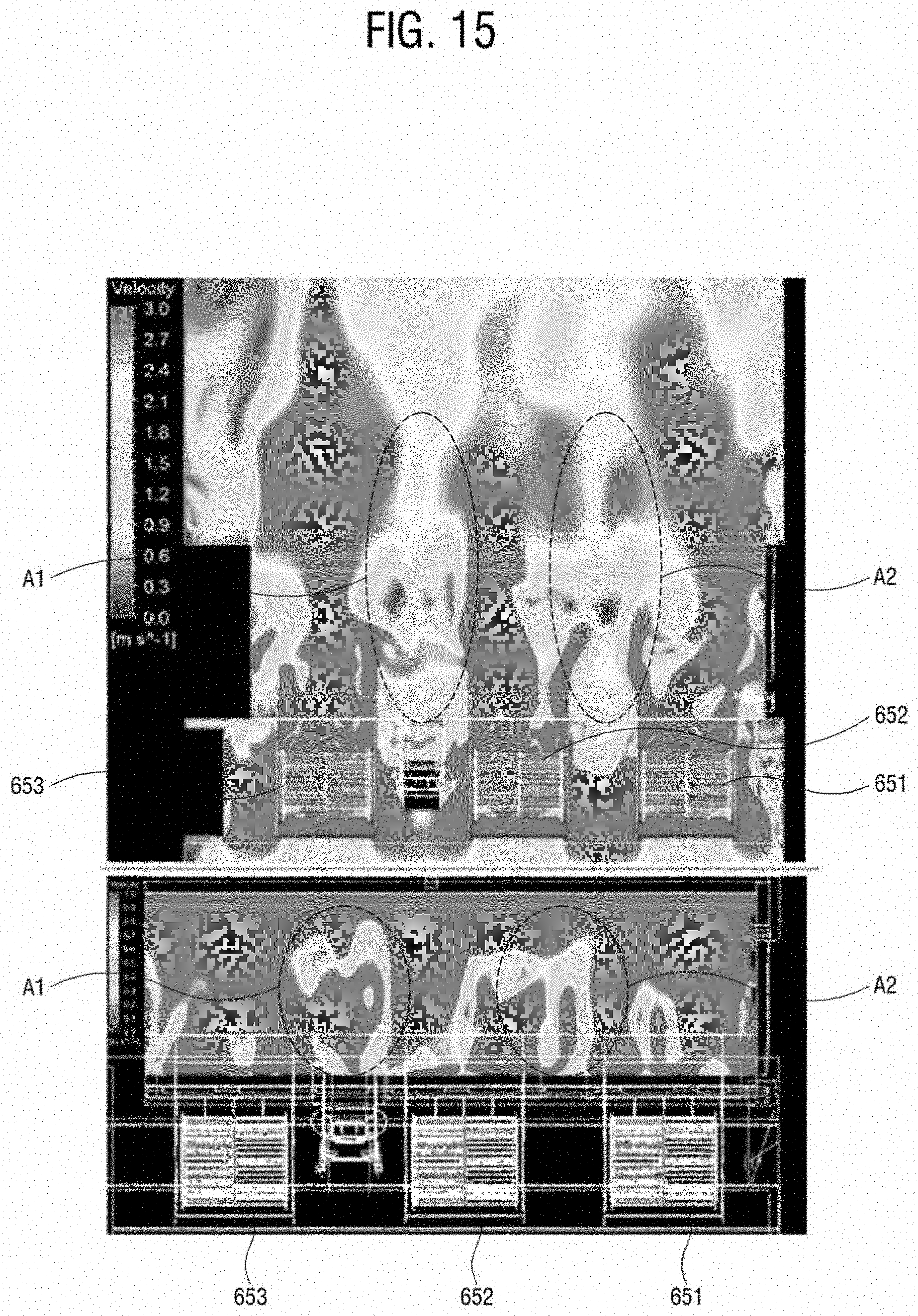
[0035] FIG. 15 illustrates a colorful speed-distribution of a moving fluid measured in an indoor unit without a guide member;
[0036] FIG. 16 illustrates a colorful speed-distribution of a moving fluid measured in an indoor unit with a guide member;
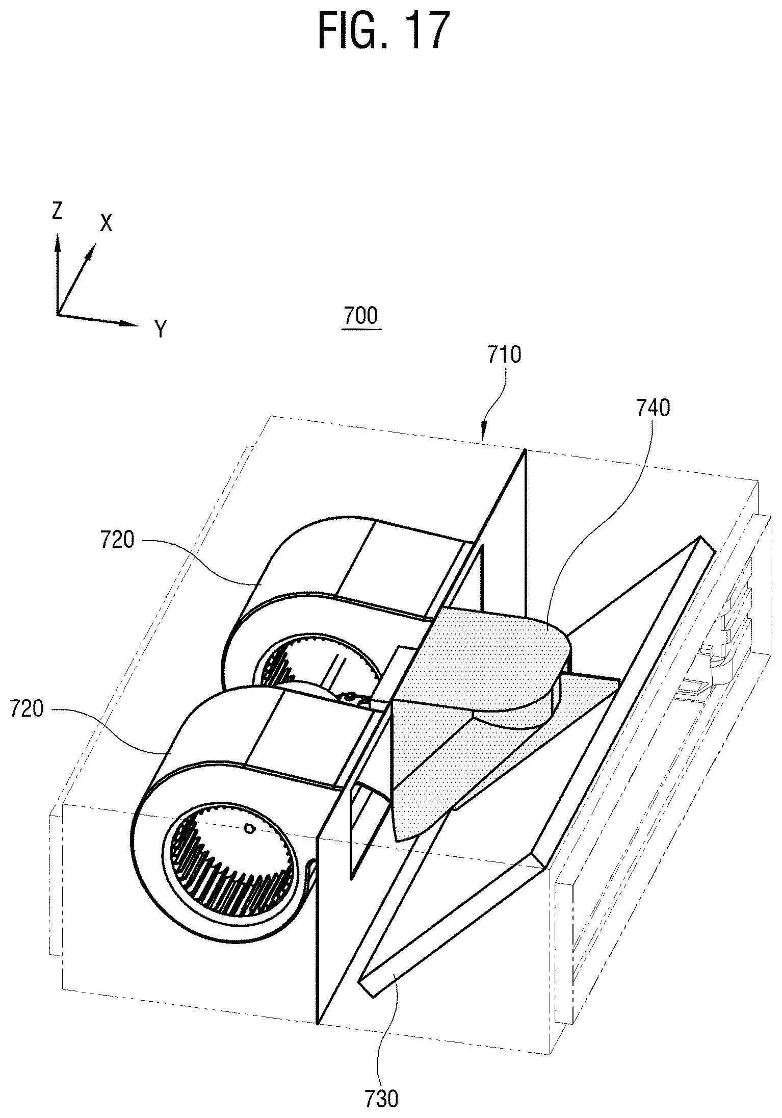
[0037] FIG. 17 is a perspective view showing that a guide member having a predetermined volume is installed in an indoor unit;
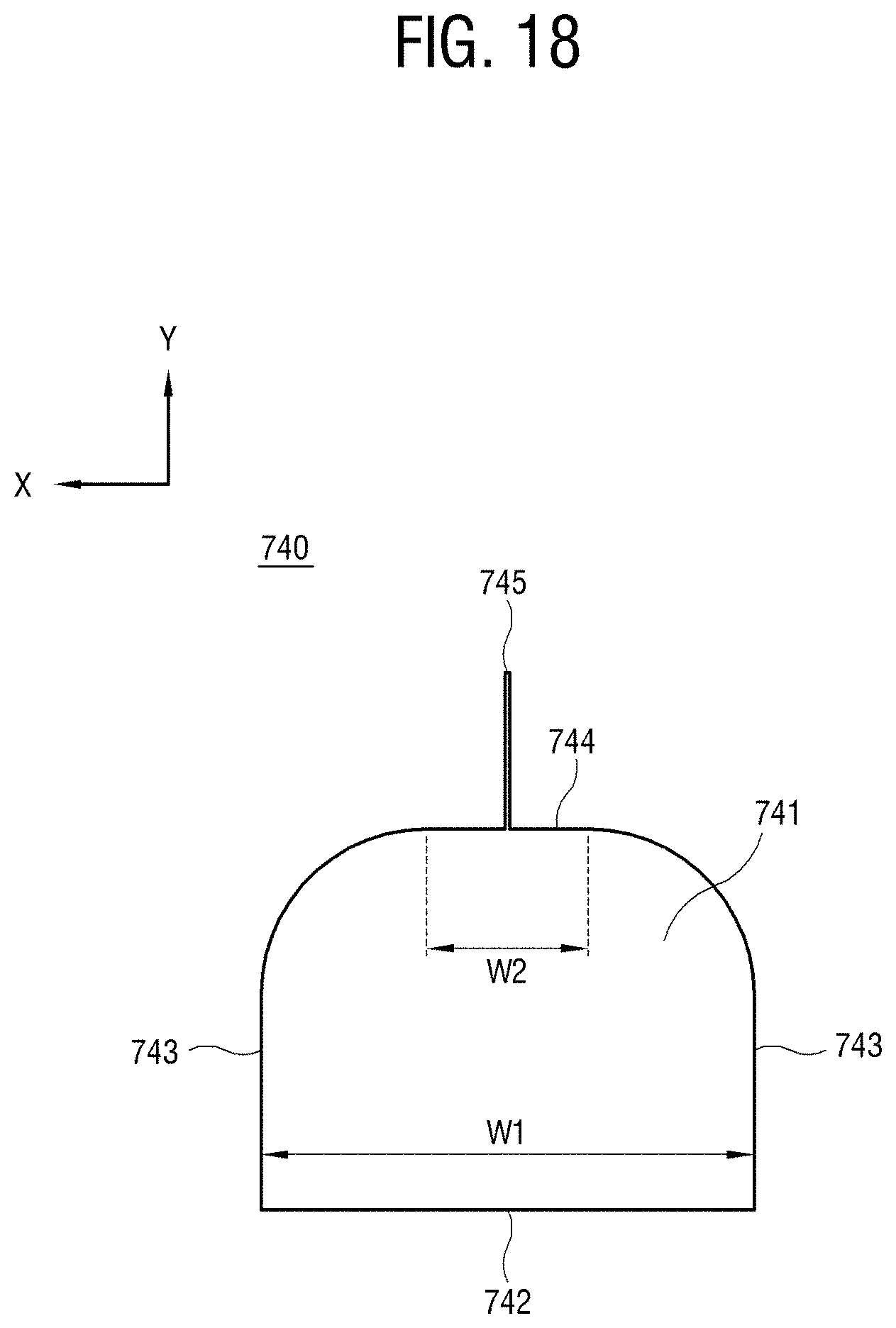
[0038] FIG. 18 is a plan view of the guide member of FIG. 17, viewed from above;
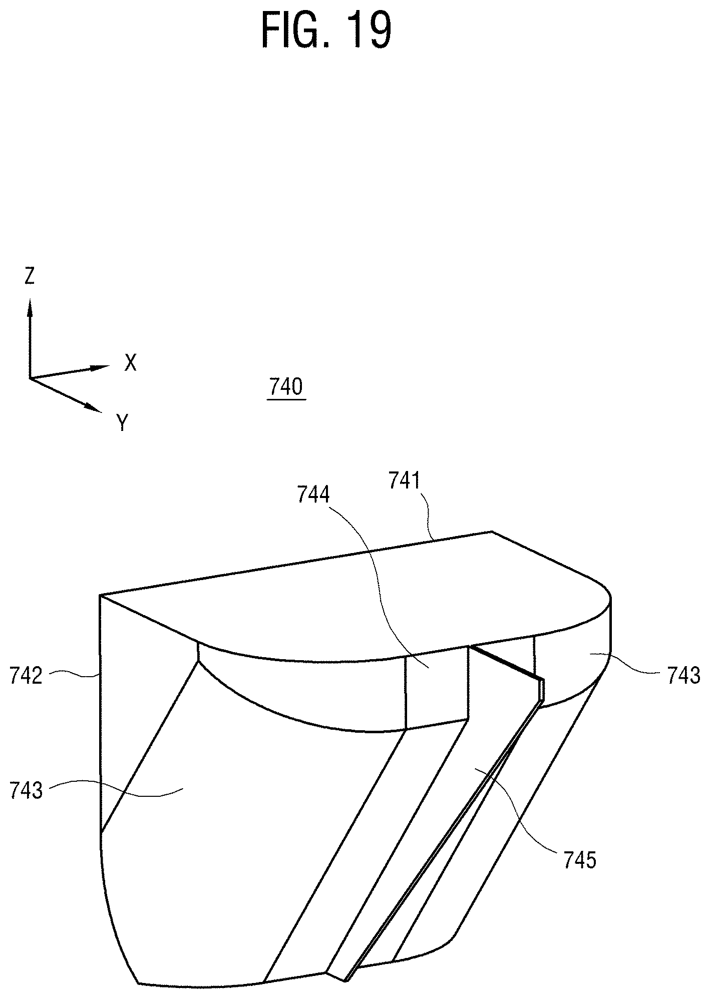
[0039] FIG. 19 is a perspective view of the guide member in FIG. 18;
[0040] FIG. 20 is a perspective view showing that a guide member having a predetermined volume is installed in an indoor unit;
[0041] FIG. 21 is a plan view of the guide member of FIG. 20, viewed from above;
[0042] FIG. 22 is a perspective view of the guide member of FIG. 20;
[0043] FIG. 23 is a plan view of the guide member of FIG. 20 with a fin;
[0044] FIG. 24 is a perspective view of the guide member of FIG. 23;
[0045] FIG. 25 illustrates a colorful speed-distribution of a moving fluid measured in an indoor unit with the guide member of FIG. 10;
[0046] FIG. 26 illustrates a colorful speed-distribution of a moving fluid measured in an indoor unit with the guide member of FIG. 18; and
[0047] FIG. 27 is a plan view showing that lateral guide members are arranged at lateral sides of a front accommodating portion in an indoor unit.
DETAILED DESCRIPTION
[0048] Below, embodiments will be described in detail with reference to accompanying drawings. Further, the embodiments described with reference to the accompanying drawings are not exclusive to each other unless otherwise mentioned, and a plurality of embodiments may be selectively combined within one apparatus. The combination of these plural embodiments may be discretionally selected and applied to realize the present inventive concept by a person having an ordinary skill in the art.
[0049] In the description of the embodiments, an ordinal number used in terms such as a first element, a second element, etc. is employed for describing variety of elements, and the terms are used for distinguishing between one element and another element. Therefore, the meanings of the elements are not limited by the terms, and the terms are also used just for explaining the corresponding embodiment without limiting the disclosure.
[0050] Further, a term "at least one" among a plurality of elements in the disclosure represents not only all the elements but also each one of the elements, which excludes the other elements or all combinations of the elements.
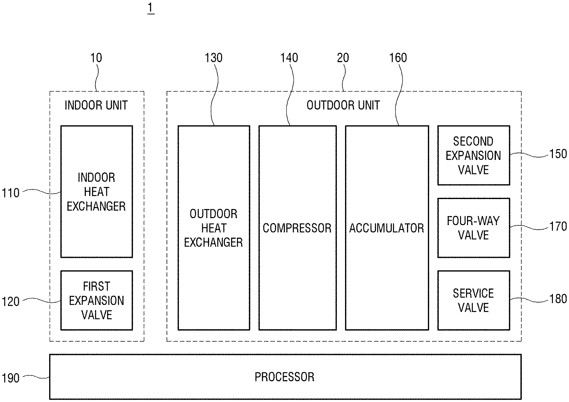
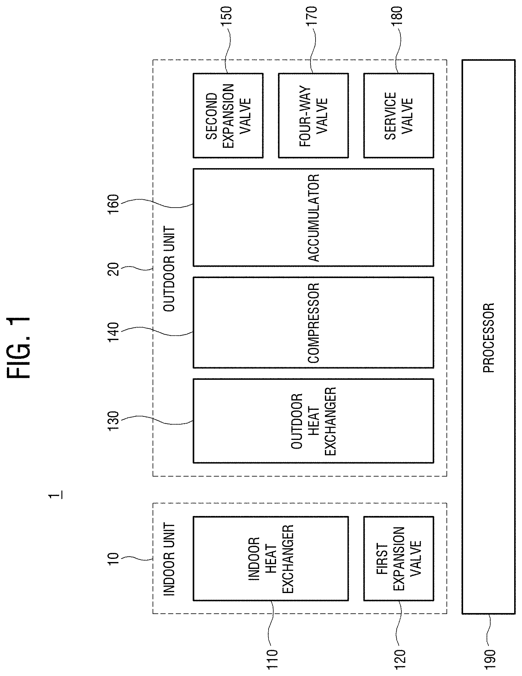
[0051] FIG. 1 is a block diagram of an air conditioner.
[0052] As shown in FIG. 1, an air conditioner according to an embodiment of the disclosure is actualized by an air cooler. The air conditioner 1 includes an indoor unit 10 to be installed in a first place having an environment of which temperature is desired to be controlled like an interior of a building, and an outdoor unit 20 to be installed in a second place free from the foregoing environment like an exterior of the building. A refrigerant circulates between the indoor unit 10 and the outdoor unit 20, and each of the indoor unit 10 and the outdoor unit 20 adjusts the state of the refrigerant based on energy, thereby controlling the temperature in the first place. The circulation of the refrigerant is achieved as an internal pipe of the indoor unit 10, an internal pipe of the outdoor unit 20, and outer pipes for connection between the indoor unit 10 and the outdoor unit 20 are connected to communicate with one another. The indoor unit 10 and the outdoor unit 20 may be variously provided in a ratio of 1:1, 1:N, N:1, N:N, etc. (where, N is a natural number).
[0053] The air conditioner 1 basically performs cooling based on heat of vaporization. The refrigerant absorbs heat when liquid is evaporated into gas, but releases heat when gas is condensed into liquid. The heat absorbed when the refrigerant is evaporated is called the heat of vaporization. Because the air conditioner 1 employs phase change of the refrigerant between liquid and gas, a refrigerant having a low evaporation point and releasing much heat of vaporization may be used in the air conditioner 1. Further, the refrigerant is required not to corrode the metal for the pipes because the indoor/outdoor pipes of the air conditioner 1 are generally made of metal. In addition, the refrigerant is required to stay in a liquid form even at a low temperature according to use locations because problems arise when the refrigerant is frozen in winter.
[0054] The air conditioner 1 includes an indoor heat exchanger 110, a first expansion valve 120, an outdoor heat exchanger 130, a compressor 140, a second expansion valve 150, an accumulator 160, a four-way valve 170, and a service valve 180. These elements are installed in the indoor unit 10 or the outdoor unit 20. The indoor unit 10 includes the indoor heat exchanger 110 and the first expansion valve 120, and the outdoor unit 20 includes the outdoor heat exchanger 130, the compressor 140, the second expansion valve 150, the accumulator 160, the four-way valve 170, and the service valve 180. Further, pipes are installed to form various routes between these elements, thereby allowing the refrigerant to move among the elements.
[0055] Further, the air conditioner 1 includes a controller or processor 190 for controlling and instructing operation of structures such as the foregoing elements of the air conditioner 1. One or more processors 190 are embodied by a hardware circuit such as a central processing unit (CPU), a micro-processor, a chipset, a system-on-chip, etc. mounted on a printed circuit board, and may be installed in one of the indoor unit 10 and the outdoor unit 20 or in each of the indoor unit 10 and the outdoor unit 20, or may be installed outside the indoor unit 10 and the outdoor unit 20.
[0056] Below, the elements will be described briefly.
[0057] The indoor heat exchanger 110 causes a phase change of a refrigerant and thus adjusts a temperature of an ambient environment based on thermal interaction between a refrigerant and air. The indoor heat exchanger 110 serves as an evaporator when the air conditioner 1 is in a cooling mode, and serves as a condenser when the air conditioner 1 is in a heating mode. In the cooling mode, the indoor heat exchanger 110 evaporates the refrigerant to cause an endothermic reaction, thereby changing the refrigerant into a gaseous state and lowering a temperature of an ambient environment. In the heating mode, the indoor heat exchanger 110 condenses a high-temperature and high-pressure refrigerant to cause an exothermic reaction, thereby changing the refrigerant into a liquid state and raising the temperature of the ambient environment.
[0058] The first expansion valve 120 expands the refrigerant condensed by the outdoor heat exchanger 130 in the cooling mode and sends it to the indoor heat exchanger 110. The first expansion valve 120 lets the refrigerant go through a route having a relatively decreased diameter to lower the pressure of the refrigerant, thereby allowing the refrigerant to easily evaporate in the future.
[0059] The outdoor heat exchanger 130 basically works in a similar way to the indoor heat exchanger 110. However, the outdoor heat exchanger 130 works on the contrary to the indoor heat exchanger 110 in each mode. In other words, the outdoor heat exchanger 130 serves as the condenser in the cooling mode and serves as the evaporator in the heating mode. The outdoor heat exchanger 130 releases heat absorbed in the indoor heat exchanger 110 in the cooling mode to thereby lower an indoor temperature, and plays the opposite role in the heating mode.
[0060] The compressor 140 compresses a gaseous cold refrigerant, which is transferred from the indoor heat exchanger 110 or the outdoor heat exchanger 130 serving as an evaporator according to modes, and adjusts the refrigerant into high-temperature and high-pressure gas. As the compressor 140 compresses the refrigerant, phase change into liquid is easily performed at a high temperature. Further, the compressor 140 receives a low-pressure refrigerant and discharges a high-pressure refrigerant, thereby urging the refrigerant to form a circulation cycle in the air conditioner 1.
[0061] The second expansion valve 150 has the same function of expanding the refrigerant as the first expansion valve 120. The second expansion valve 150 expands the refrigerant condensed by the indoor heat exchanger 110 in the heating mode and sends it to the outdoor heat exchanger 130.
[0062] The accumulator 160 sends only a gaseous refrigerant of an introduced refrigerant to the compressor 140. The evaporated refrigerant may not completely evaporate but occasionally include a liquid refrigerant, and thus the accumulator 160 prevents the liquid refrigerant from being introduced into the compressor 140.
[0063] The four-way valve 170 changes the route of the refrigerant in the outdoor unit 20 based on one of the cooling mode and the heating mode. The four-way valve 170 adjusts the movement of the refrigerant based on the current mode, thereby switching over between the indoor heat exchanger 110 and the outdoor heat exchanger 130 according to the modes.
[0064] The service valve 180 refers to a valve for allowing a manager to control a vacuum state and replenish a refrigerant, in the circulation cycle for the refrigerant through the pipes of the air conditioner 1. When a cooling/heating efficiency is lowered due to the lack of the refrigerant in the cycle with increased use time, the refrigerant may be replenished through the service valve 180.
[0065] In this embodiment the indoor unit 10 is embodied by a duct-type indoor unit. Below, an installed type and structure of the indoor unit 10 according to this embodiment will be described.
[0066] FIG. 2 illustrates an example that an indoor unit is installed.
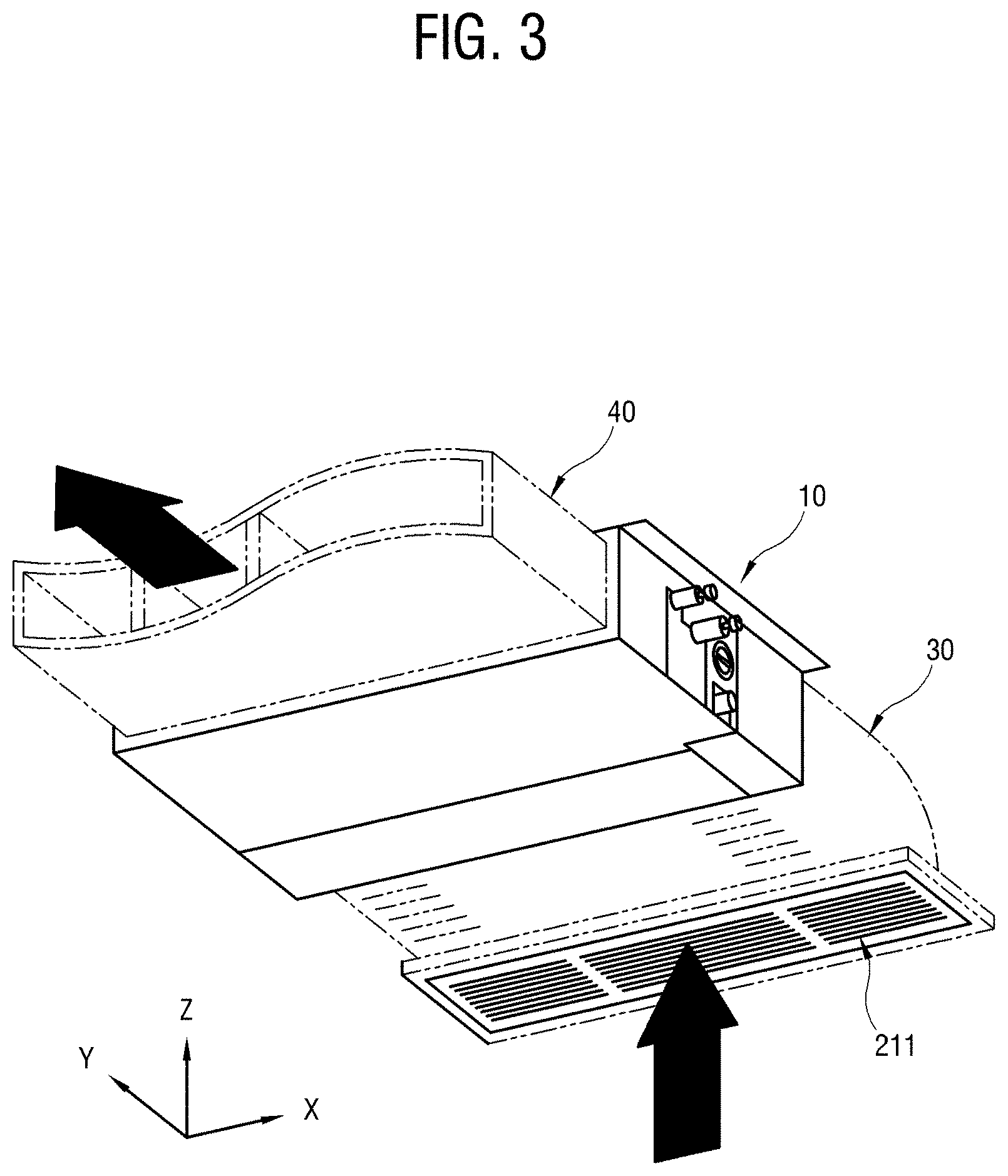
[0067] FIG. 3 is a perspective view showing that an inhaling duct and a discharging duct are coupled to the indoor unit.
[0068] As shown in FIGS. 2 and 3, an indoor environment is divided into a lower space 220 below a ceiling 210, and an upper space 230 above the ceiling 210. Typically, the lower space 220 refers to a room in which a user is present, a living room, etc. of which air is cooled or heated by the indoor unit 10. The upper space 230 refers to a space under a roof in a case of a one-storied house, and a space hidden from a user, who is present in the lower space 220, behind the ceiling 210.
[0069] In the accompanying drawings, axes X, Y and Z are orthogonal to one another. The axis X refers to the left and right directions of the indoor unit. The axis Y refers to the front and back directions of the indoor unit, i.e. a main direction in which air flows. The axis Z refers to the upward and downward directions of the indoor unit.
[0070] The indoor unit 10 is installed in the upper space 230. The indoor unit 10 has one side communicating with an air inlet 211 formed in the ceiling 210, and the other side communicating with an air outlet 212 formed in the ceiling 210 and spaced apart from the air inlet 211. In this embodiment, the air inlet 211 is horizontally disposed, and the air outlet 212 is vertically disposed. However, this embodiment is merely an example. Alternatively, the air inlet 211 and the air outlet 212 may be variously disposed. The indoor unit 10 is opened backward and forward, and couples with an inhaling duct 30 and a discharging duct 40.
[0071] The inhaling duct 30 is provided between the indoor unit 10 and the air inlet 211. The inhaling duct 30 guides air, which is inhaled from the lower space 220 into the air inlet 211, toward the inside of the indoor unit 10. On the other hand, the discharging duct 40 is provided between the indoor unit 10 and the air outlet 212. The discharging duct 40 guides air, which is subjected to heat exchange inside the indoor unit 10, for example, cooled air toward the air outlet 212, thereby discharging the cooled air toward the lower space 220.
[0072] The lower space 220 is cooled with the cooled air discharged through the air outlet 212. The air circulating in the lower space 220 is inhaled into the inhaling duct 30 through the air inlet 211. The air flowing in the inhaling duct 30 is introduced into the indoor unit 10. Based on such circulation, the indoor unit 10 cools the lower space 220.
[0073] In this embodiment, the discharging duct 40 and the air outlet 212 are grouped as one set. Alternatively, a plurality of sets of discharging ducts 40 and air outlets 212 may be provided. When the air outlets 212 are provided at a plurality of spaced positions, the plurality of discharging ducts 40 from the indoor unit 10 are respectively connected to the air outlets 212, so that the indoor unit 10 can cool many places at a time.
[0074] Below, the structure of the indoor unit 10 will be described.
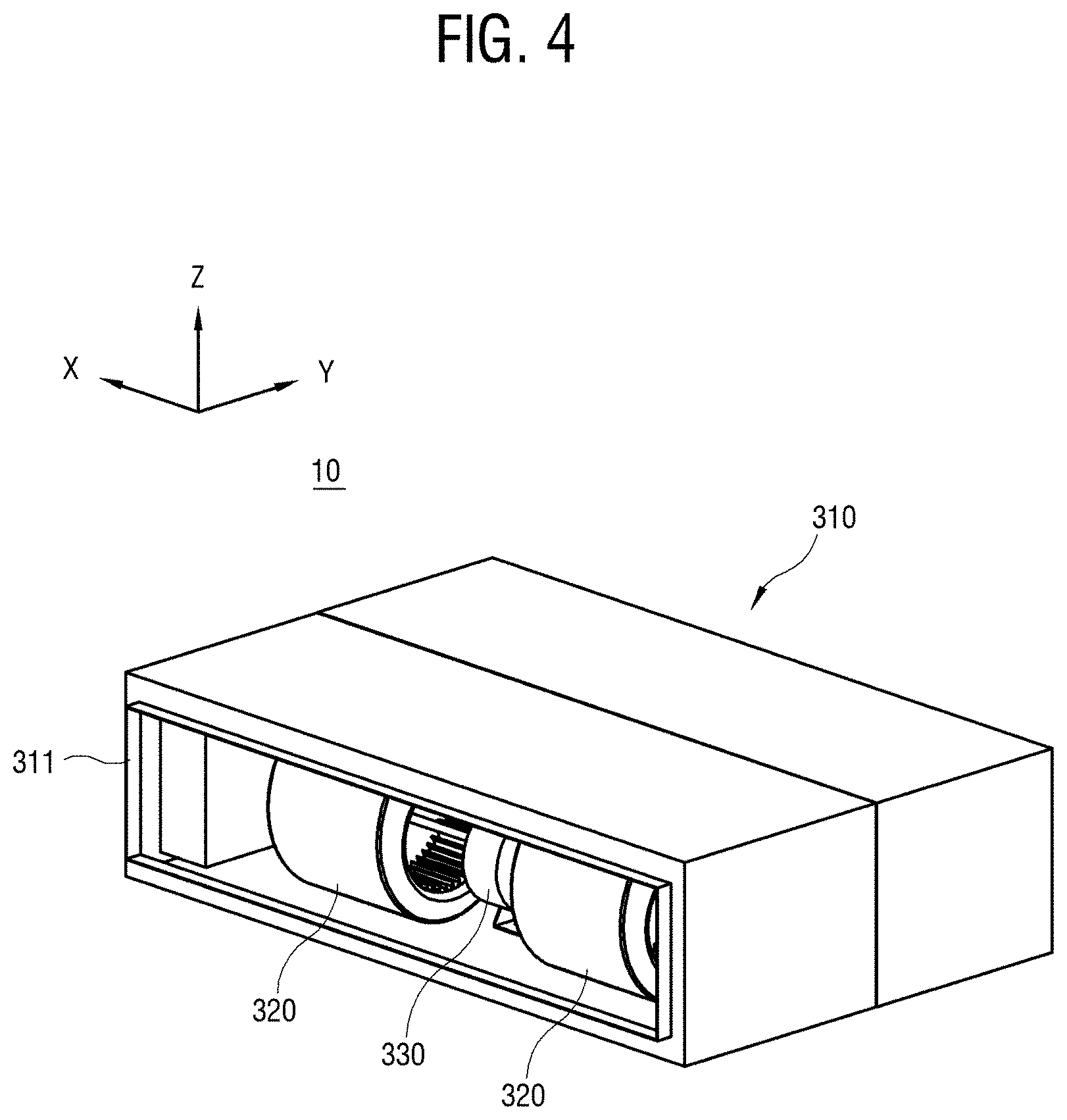
[0075] FIG. 4 is a perspective view showing an inhaling side of an indoor unit.
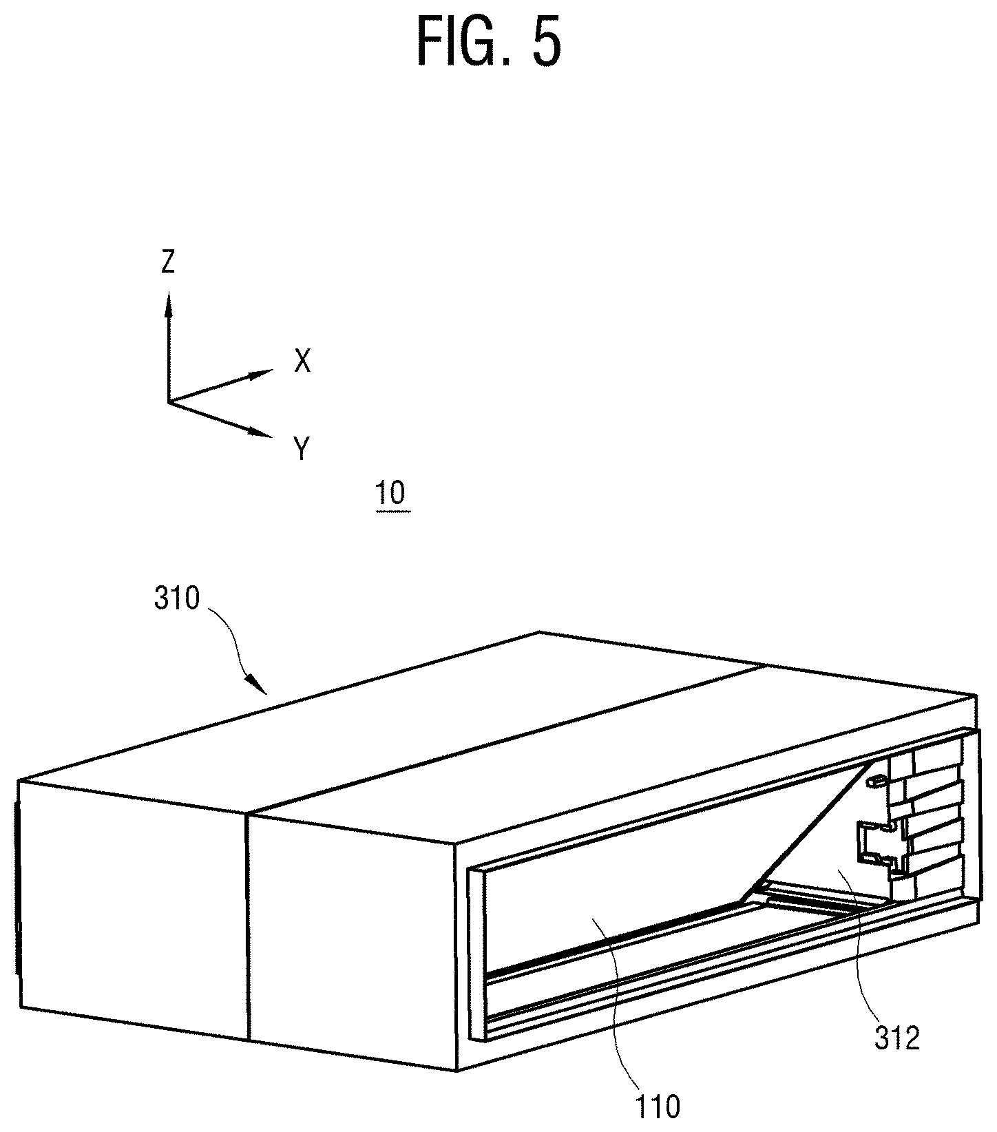
[0076] FIG. 5 is a perspective view showing a discharging side of an indoor unit.
[0077] As shown in FIGS. 4 and 5, the indoor unit 10 includes a main housing 310 shaped like a rectangular parallelepiped, a plurality of air-blowing units 320 disposed at the inhaling or rear side of the main housing 310, an indoor heat exchanger 110 disposed at the discharging or front side of the main housing 310, and a motor 330 disposed near the plurality of air-blowing units 320. In the following embodiments, the indoor heat exchanger 110 will be briefly called a heat exchanger 110.
[0078] The main housing 310 includes a rear opening 311 formed on the rear, and a front opening 312 formed on the front. The rear opening 311 refers to an opening through which air is introduced from the outside of the indoor unit 10 into the indoor unit 10. The front opening 312 refers to an opening through which air is discharged from the inside of the indoor unit 10 to the outside of the indoor unit 10. For convenience of description, the main housing 310 may be divided into an inhaling side region (or a rear region) and a discharging side region (or a front area) with respect to the axis Y, i.e. the main direction in which air flows. In this embodiment, the discharging side region and the inhaling side region may also be called a first accommodating portion and a second accommodating portion, respectively. The main housing 310 accommodates the air-blowing unit 320 in the inhaling side region, and the heat exchanger 110 in the discharging side region.
[0079] The air-blowing unit 320 blows air toward the heat exchanger 110. The air-blowing unit 320 employs the motor 330 to drive an internal fan so as to inhale air though the rear opening 311, and sends the inhaled air to the heat exchanger 110. In this embodiment, the air-blowing unit 320 includes two units arranged in parallel along the axis X. Alternatively, the air-blowing unit 320 may be designed to include three or more units. Further, the air-blowing unit 320 may be embodied by various fan units. In this embodiment, the air-blowing unit 320 may be embodied by a centrifugal fan or a sirocco fan.
[0080] The reason why the sirocco fan is used as the air-blowing unit 320 is as follows. According to this embodiment, the indoor unit 10 is provided as the duct-type indoor unit, and couples with a plurality of discharging ducts through the front opening 312, thereby discharging the cooled air to a plurality of positions. As a parameter of an airflow rate in the duct-type indoor unit, there is static pressure. As the total length of the discharging duct connected to the indoor unit 10 increases and the number of discharging ducts increases, a load applied to the indoor unit 10 becomes higher. To cope with such a high load, the indoor unit 10 needs the air-blowing unit 320 having high static-pressure performance. Among various kinds of fan units, the sirocco fan keeps an appropriate airflow rate even when the load is high, and this means that the sirocco fan is relatively excellent in the static-pressure performance. From this point of view, the air-blowing unit 320 is embodied by the sirocco fan when the indoor unit 10 is the duct-type indoor unit. Further, when the air-blowing unit 320 is embodied by the sirocco fan, it is possible to relatively reduce noise.
[0081] The heat exchanger 110 exchanges heat with the refrigerant so as to adjust the temperature of air passing through the heat exchanger 110. The heat exchanger 110 includes a pipe through which the refrigerant passes, and a fin extended from the pipe. Both the pipe and the fin contain metal excellent in thermal conductivity. While air passes through the pipe and the fin of the heat exchanger 110, the air exchanges heat with the pipe and the fin. The air, which is subjected to the heat exchange via passing through the heat exchanger 110, is discharged to the outside of the main housing 310 through the front opening 312.
[0082] According to this embodiment, the heat exchanger 110 is not vertically disposed in parallel with the axis Z, but the heat exchanger 110 is not vertically disposed in parallel with the axis Z, and the upper side of the heat exchanger 110 is inclined at a predetermined angle to the axis Z. This is designed to enlarge the area of the heat exchanger 110 to be in contact with air.
[0083] Below, the air-blowing unit 320 will be described.
[0084] FIG. 6 is a perspective view showing an outer appearance of an air-blowing unit.
[0085] As shown in FIG. 6, the air-blowing unit 320 includes an air-blowing unit housing 321, and a centrifugal fan 324 rotatably accommodated in the air-blowing unit housing 321.
[0086] The air-blowing unit housing 321 includes an air-blowing unit inlet 322 formed at one side oriented in the direction of X or -X to inhale air, and an air-blowing unit outlet 323 formed at one side oriented in the direction of Y to exhale the air. In other words, the air-blowing unit 320 is designed to have an air inhaling direction and an air exhaling direction which are substantially perpendicular to each other, and this is because the centrifugal fan 324 is structurally provided as the sirocco fan.
[0087] The centrifugal fan 324 includes a plurality of blades 325 arranged in parallel with a rotational axis, and a fan frame 326 supporting the plurality of blades 325. The plurality of blades 325 extended in parallel along the axis X are arranged to have substantially the same distance from the rotational axis on the plane Y-Z. The plurality of blades 325 is coupled to the fan frame 326 shaped like a cylinder, and the fan frame 326 is rotatably coupled to the air-blowing unit housing 321 and the motor. The motor is driven to rotate the fan frame 326, thereby rotating the plurality of blades 325. With this structure, air is introduced into the air-blowing unit housing 321 through the air-blowing unit inlet 322 along the rotational axis of the centrifugal fan 324, and then discharged through the air-blowing unit outlet 323 in a radial direction of the centrifugal fan 324 based on centrifugal force generated by the rotating centrifugal fan 324.
[0088] Below, an overall structure of an indoor unit according to an embodiment of the disclosure will be described.
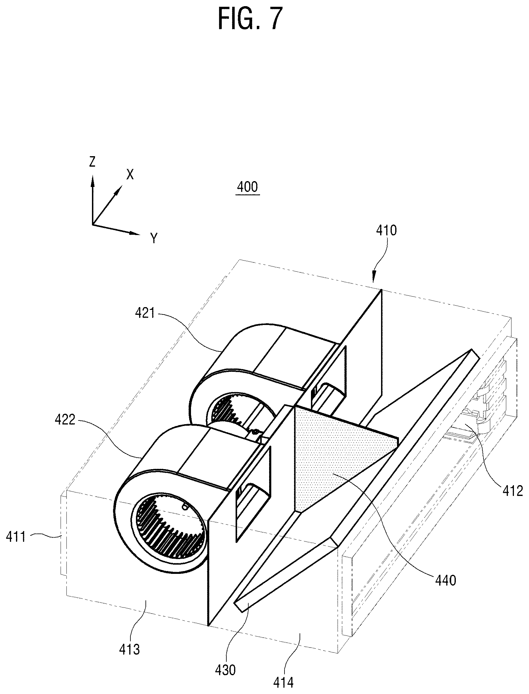
[0089] FIG. 7 is a partial perspective view of an indoor unit.
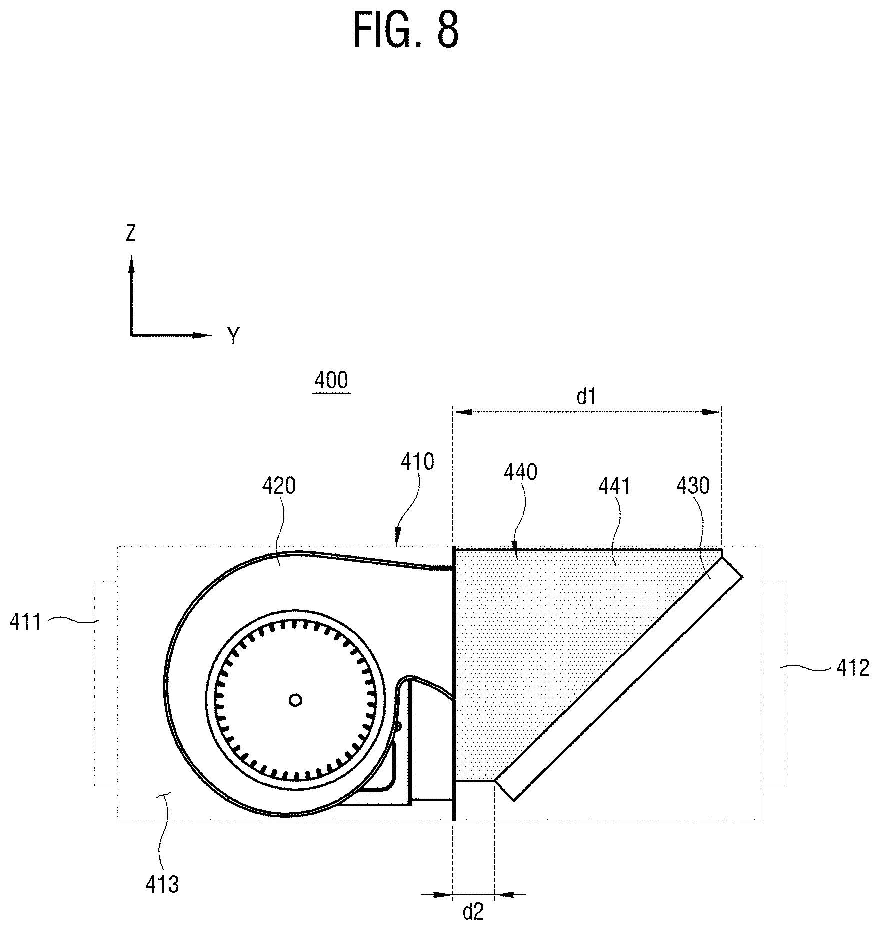
[0090] FIG. 8 is a lateral view of the indoor unit of FIG. 7.
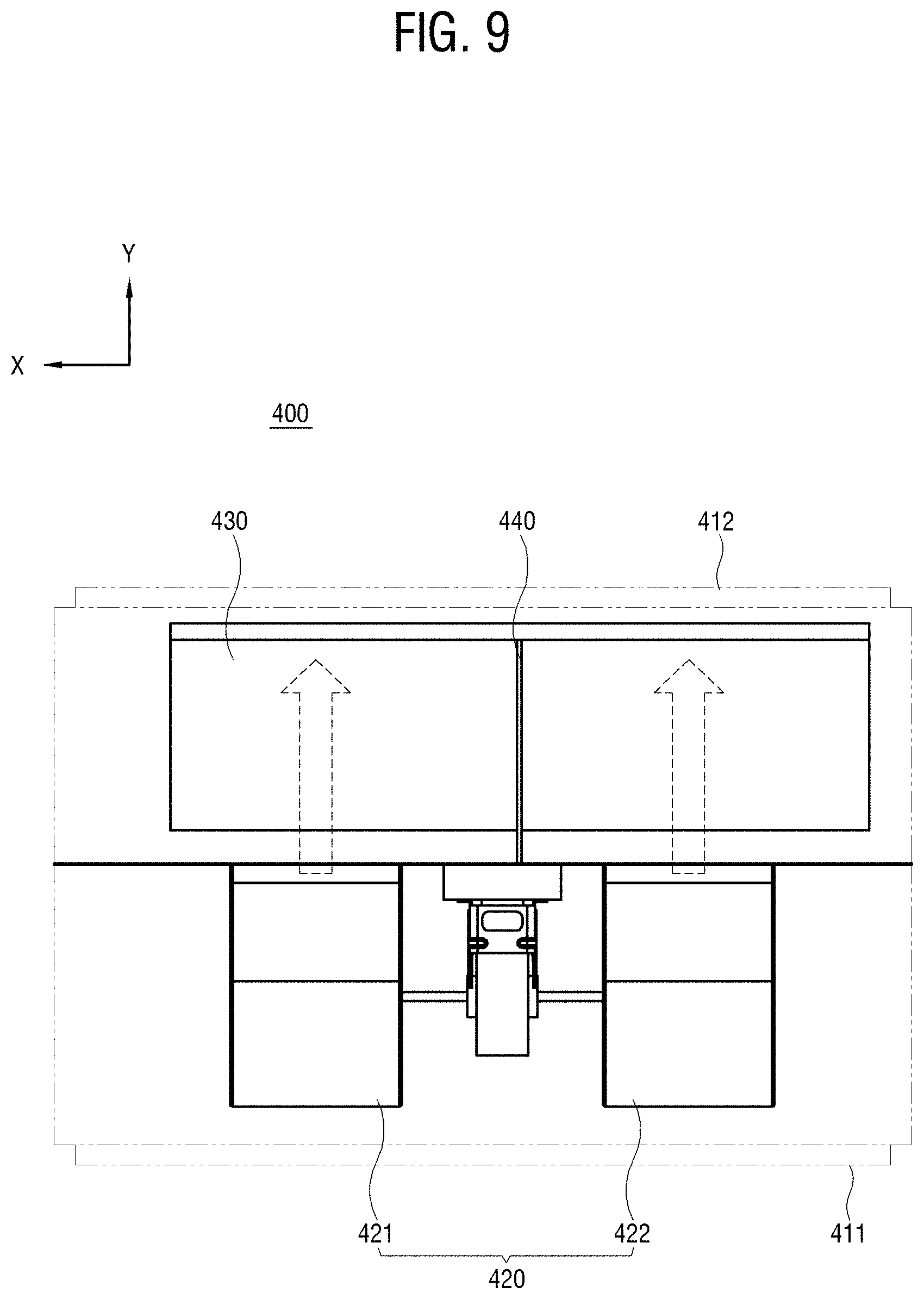
[0091] FIG. 9 is a plan view of the indoor unit of FIG. 7.
[0092] As shown in FIGS. 7, 8 and 9, an indoor unit 400 includes a main housing 410, a rear opening 411, a front opening 412, an air-blowing unit 420, and a heat exchanger 430.
[0093] The main housing 410 may be divided into a rear inhaling-side accommodating portion or a rear accommodating portion 413, and a front discharging side accommodating portion or a front accommodating portion 414. The rear accommodating portion 413 and the front accommodating portion 414 are merely expressed for convenience of description. Alternatively, the rear accommodating portion 413 and the front accommodating portion 414 may be called a first accommodating portion and a second accommodating portion. The rear accommodating portion 413 accommodates the air-blowing unit 420 therein, and the front accommodating portion 414 accommodates the heat exchanger 430 therein. Air inhaled into the rear accommodating portion 413 of the main housing 410 through the rear opening 411 is introduced into the air-blowing unit 420. The air introduced into the air-blowing unit 420 is sent to the heat exchanger 430 provided in the front accommodating portion 414 of the main housing 410 by centrifugal force of the air-blowing unit 420. Then, the air exchanges heat with the heat exchanger 430 and is discharged to the outside of the main housing 410 through the front opening 412.
[0094] Further, the air-blowing unit 420 according to this embodiment includes a first air-blowing unit 421 and a second air-blowing unit 422 which are arranged in parallel leaving a predetermined distance therebetween in the direction of Y. Both the first air-blowing unit 421 and the second air-blowing unit 422 discharge air in the direction of Y.
[0095] The heat exchanger 430 is microscopically shaped like a plate, but has a structure including a pipe through which the refrigerant passes and a fin extended from the pipe. The heat exchanger 430 is extended in parallel with the rear accommodating portion 413, and accommodated in the main housing 410 as its upper edge is inclined forward.
[0096] In other words, a distance of `d1` between the upper edge of the heat exchanger 430 and the air-blowing unit 420 and a distance of `d2` between the lower edge of the heat exchanger 430 and the air-blowing unit 420 are given to satisfy `d1>d2`. Alternatively, `d1` may be a distance between the upper edge of the heat exchanger 430 and the rear accommodating portion 413 and `d2` may be a distance between the upper edge of the heat exchanger 430 and the rear accommodating portion 413. Because the heat exchanger 430 is disposed as above, it is possible to relatively increase the area for exchanging heat with the area. Although the area for exchanging heat with air is relatively increased even in a case of `d1<d2`, `d1>d2` is preferable because it is natural that air flows down because of gravity.
[0097] Here, the indoor unit 400 according to this embodiment includes a guide member 440 extended from the rear accommodating portion 413 between the first air-blowing unit 421 and the second air-blowing unit 422 toward the heat exchanger 430 and provided in the front accommodating portion 414. The guide member 440 has a guide surface 441 for guiding air discharged from the rear accommodating portion 413 toward the front accommodating portion 414 by the first air-blowing unit 421 and the second air-blowing unit 422.
[0098] For comparison, it will be assumed that the indoor unit 400 does not include the guide member 440. In this case, a recirculation flow occurs in the front accommodating portion 414 because of external static pressure. In particular, a flow loss caused by recirculation increases as the external static pressure becomes higher. Specifically, for convenience of description, a certain region of the front accommodating portion 414 positioned between the first air-blowing unit 421 and the second air-blowing unit 422 will be called a middle region. In this middle region, air flowing from the first air-blowing unit 421 and air flowing from the second air-blowing unit 422 are mixed. This mixture causes the flow loss, thereby decreasing a flow rate of air discharged from the indoor unit 400.
[0099] On the other hand, the guide member 440 according to this embodiment divides the front accommodating portion 414 into a first channel through which air discharged from the first air-blowing unit 421 reaches the heat exchanger 430 and a second channel through which air discharged from the second air-blowing unit 422 reaches the heat exchanger 430. Thus, the guide member 440 of the indoor unit 400 can prevent turbulence or swirl caused by the mixture of the plurality of air flows in the middle region, and guides the air discharged from the first air-blowing unit 421 and the air discharged from the second air-blowing unit 422 to individually reach the heat exchanger 430. In this regard, the guide member 440 may also be called a divider.
[0100] Further, the guide member 440 of the indoor unit 400 can prevents speed of moving fluid from slowing down in the middle region.
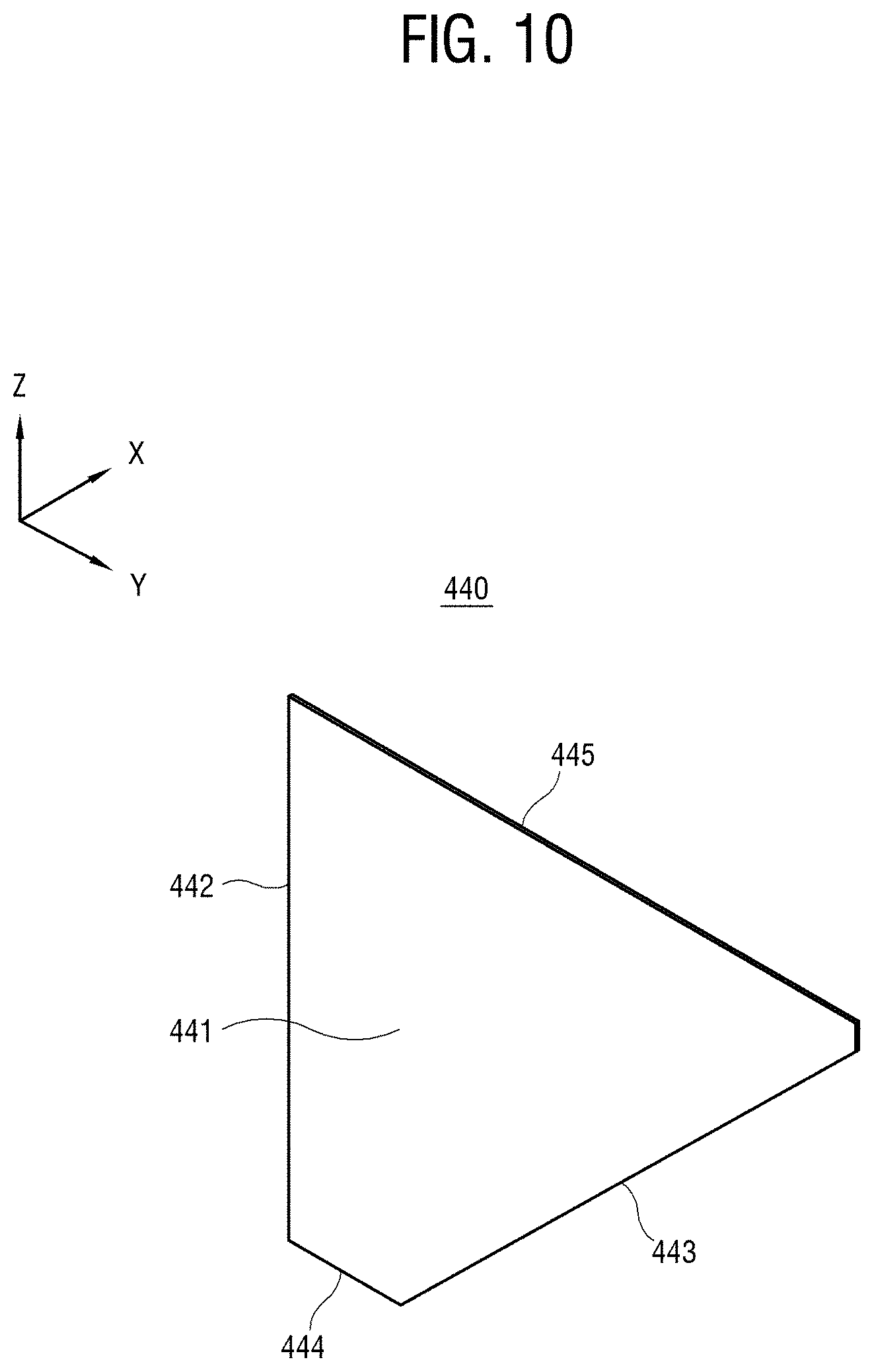
[0101] FIG. 10 is a perspective view of a guide member.
[0102] As shown in FIG. 10, the guide member 440 includes a guide surface 441 surrounded with a rear edge 442, a front edge 443, a lower edge 444, and an upper edge 445. The rear edge 442 substantially stands, and faces the rear accommodating portion of the main housing in which the air-blowing unit is provided. However, the heat exchanger has a structure of being inclined frontward, and therefore the front edge 443, the lower edge 444 and the upper edge 445 have shapes and lengths corresponding to the structure of the heat exchanger.
[0103] Because the front edge 443 is extended substantially in parallel with the plate surface of the heat exchanger, the upper side is inclined frontward at a predetermined angle. The front edge 443 may be in contact with or spaced apart from the plate surface of the heat exchanger. The lower edge 444 faces the lower plate surface of the main housing. The upper edge 445 is extended in parallel with the lower edge 444, and faces the upper plate surface of the main housing. Because the lower edge of the heat exchanger is near to the air-blowing unit and the upper edge of the heat exchanger is spaced apart from the air-blowing unit, the lower edge 444 is shorter than the upper edge 445.
[0104] The guide surface 441 may have an even surface, but may be designed to have a surface formed with a predetermined uneven pattern. This will be described later.
[0105] Below, the indoor unit, of which performance is improved by the guide member 440, will be described.
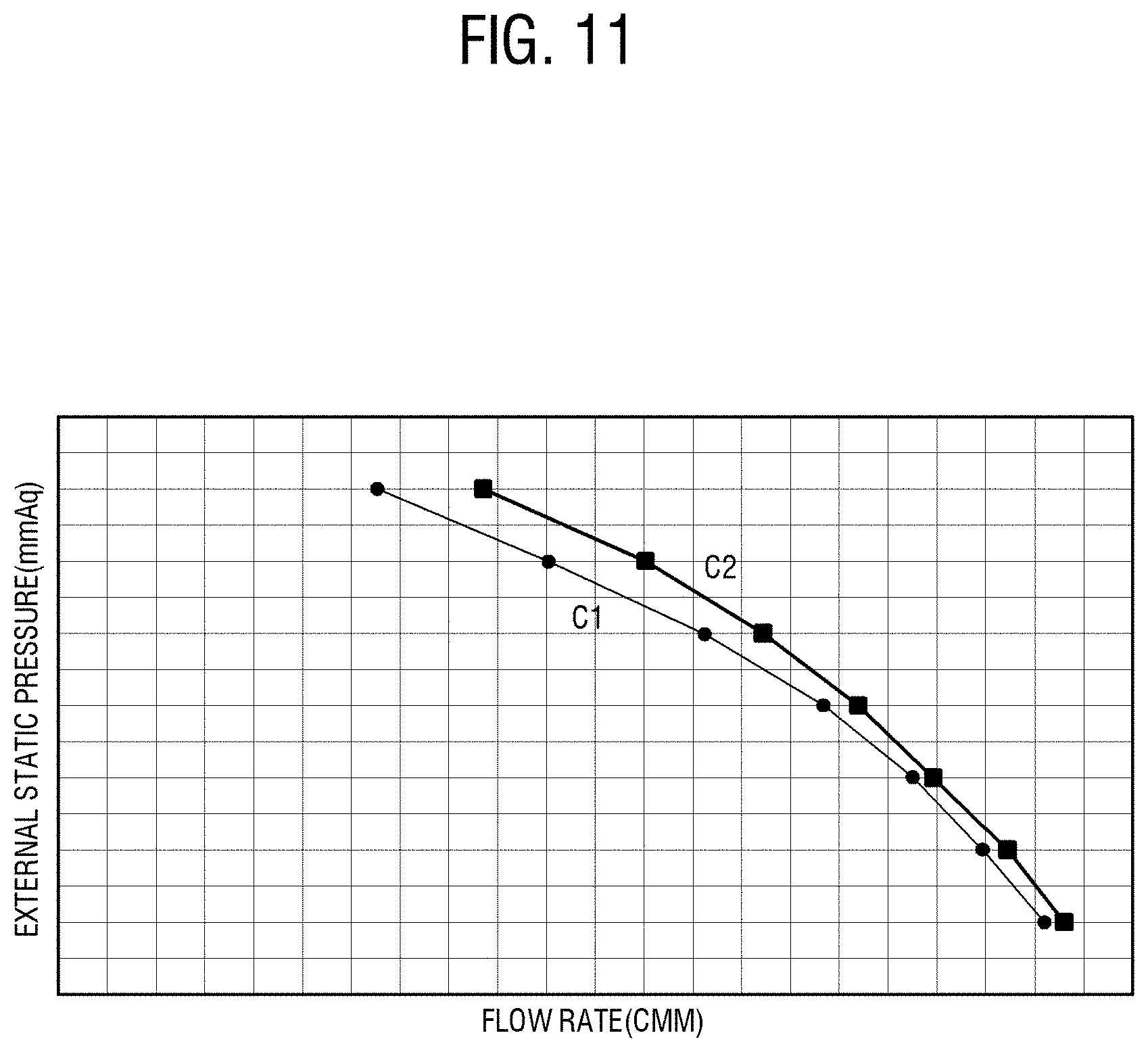
[0106] FIG. 11 is a graph showing comparison in static-pressure performance between a case where a guide member is applied to the indoor unit and a case where the guide member is not applied to the indoor unit.
[0107] As shown in FIG. 11, comparison between a flow rate of air measured when the guide member is applied to the indoor unit and a flow rate of air measured when the guide member is not applied to the indoor unit may be carried out with respect to external static pressure. In this graph, the abscissa indicates the flowing amount, the ordinate indicates the external static pressure, the curve `C1` indicates a case of excluding guide member, and the curve `C2` indicates a case of including the guide member. This graph is merely given to compare the results of `C1` and `C2`, and therefore detailed numerical values of experimental results will be omitted.
[0108] When the external static pressure is low, i.e. when a load applied to the indoor unit is low, the indoor unit needs less capacity for cooling a place, a small number of discharging ducts are used in discharging the cooled air from the indoor unit, and a total length of the discharging duct is short. On the other hand, when the external static pressure is high, i.e. when a load applied to the indoor unit is high, the indoor unit needs more capacity for cooling a place, a large number of discharging ducts are used in discharging the cooled air from the indoor unit, and a total length of the discharging ducts is long.
[0109] According to this graph, under the same condition of the external static pressure, the flow rate of `C2` is higher than the flow rate of Based on this result, it will be appreciated that difference in the flow rate in a case of high external static pressure is larger than that in a case of low external static pressure. In terms of securing the flow rate, this means that the guide member according to this embodiment more advantageously works at high external static pressure.
[0110] FIG. 12 is a graph showing comparison air-blowing noise between a case where a guide member is applied to the indoor unit and a case where the guide member is not applied to the indoor unit.
[0111] As shown in FIG. 12, comparison between a flow rate of air measured when the guide member is applied to the indoor unit and a flow rate of air measured when the guide member is not applied to the indoor unit may be carried out with respect to the air-blowing noise. Here, the flow rate of air was measured as divided into a case of relatively low static pressure and a case of relatively high static pressure. The curve `C3` indicates a case of excluding the guide member when the static pressure is low, and the curve `C4` indicates a case of including the guide member under the same static pressure condition as that of the curve C3. Meanwhile, the curve `C5` indicates a case of excluding the guide member when the static pressure is high, and the curve `C6` indicates a case of including the guide member under the same static pressure condition as that of the curve C5.
[0112] According to this graph, under the same condition of air-blowing noise, the flow rate of `C4` is higher than that of `C3` and the flow rate of `C6` is higher than that of `C5`. However, under the same condition of air-blowing noise, difference in the flow rate between `C6` and `C5` is larger than that between `C4` and `C3`. In terms of silence, this means that the guide member according to this embodiment more advantageously works at high external static pressure.
[0113] Like this, the indoor unit including the guide member according to this embodiment is more effective in securing the flow rate and the silence than that excluding the guide member. Further, this effect is remarkable when the external static pressure is high.
[0114] Below, various alternative embodiments of the guide member will be described.
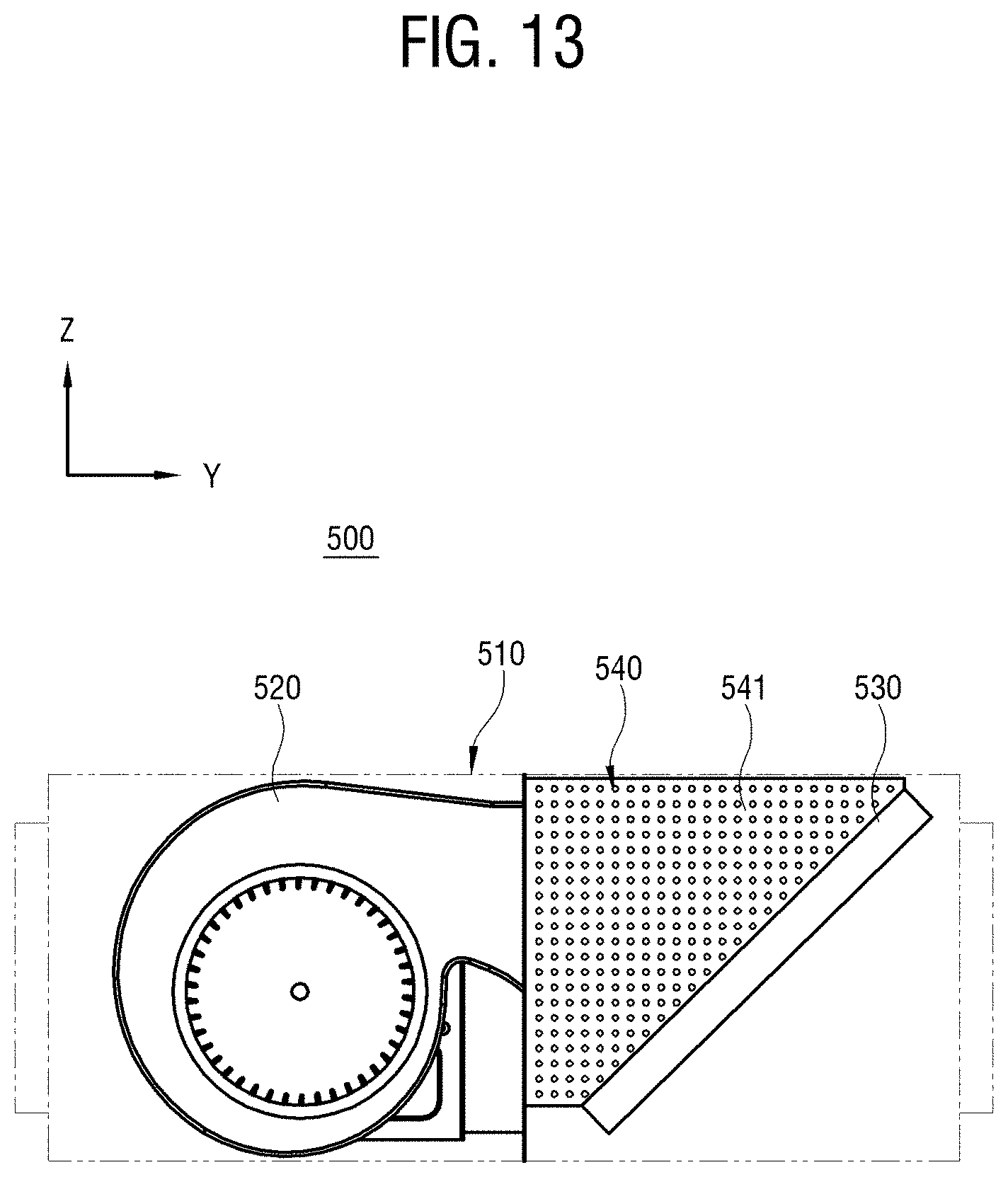
[0115] FIG. 13 is a lateral view of an indoor unit with a guide member having a guide surface.
[0116] As shown in FIG. 13, an indoor unit 500 according to this embodiment includes a main housing 510 internally divided into a rear accommodating portion and a front accommodating portion, an air-blowing unit 520 placed in the rear accommodating portion, a heat exchanger 530 placed in a front accommodating portion, and a guide member 540 placed in the front accommodating portion. The basic structure of the indoor unit 500 in this embodiment is substantially the same as that of the foregoing embodiment, and thus detailed descriptions thereof will be omitted. However, the guide member 540 in this embodiment includes a guide surface 541 formed with a predetermined uneven pattern instead of the even guide surface unlike that of the foregoing embodiment. The uneven pattern formed on the guide surface 541 may be achieved by a dimple pattern including one or more recesses, an embossing pattern including a plurality of projections, etc.
[0117] The guide member 540 having the guide surface 541 with the uneven pattern is more improved in a separation delay effect than that having the even guide surface. Air discharged from the air-blowing unit 520 moves as being attached to the guide surface 541 when the air is sent to the heat exchanger 530 along the guide surface 541. Flow speed of air moving as attached to the guide surface 541 is faster than that of air moving as being detached from the guide surface 541. Therefore, in terms of the flow speed of air, it is advantageous to prevent air moving as attached to the guide surface 541 from being detached from the guide surface 541. The separation delay effect is that air attached to the guide surface 541 is interrupted from separation from the guide surface 541. According to this embodiment, the guide surface 541 has a structure to relatively improve the separation delay effect.
[0118] Meanwhile, the foregoing embodiments described the indoor units including two air-blowing units. In these cases, the guide member is interposed between two air-blowing units and therefore one guide member is applied to the indoor unit. However, three or more air-blowing units may be employed, and the number of guide members is varied depending on the number of air-blowing units. Below, an indoor unit with three air-blowing units will be described.
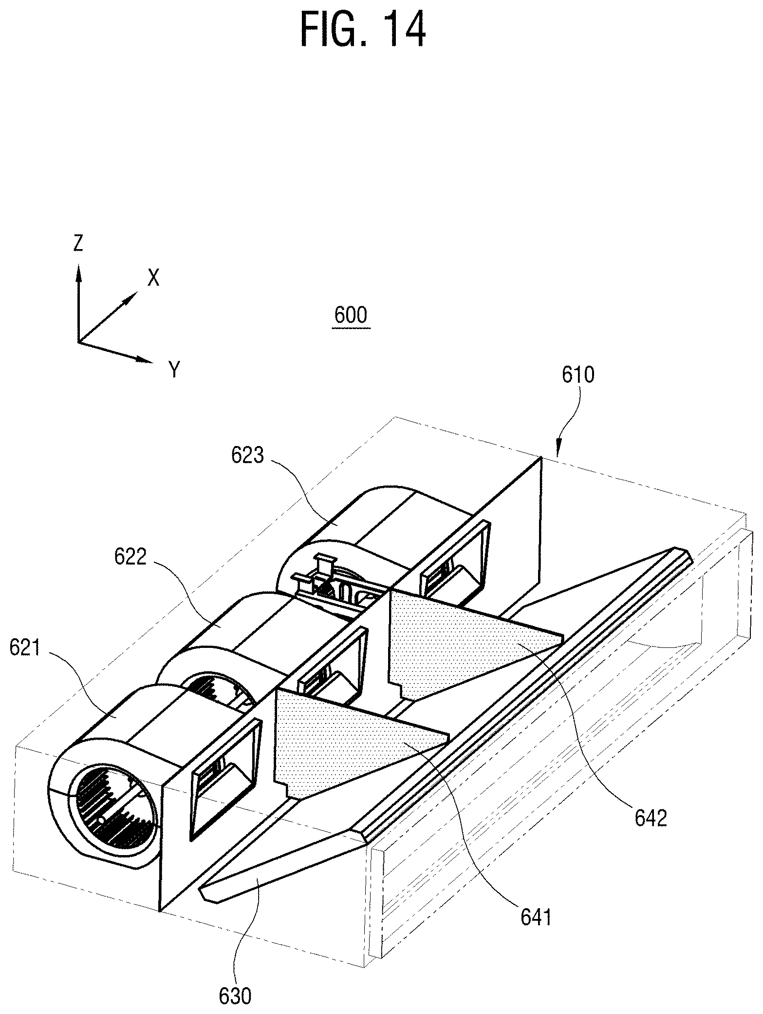
[0119] FIG. 14 is a perspective view of an indoor unit including three air-blowing units.
[0120] As shown in FIG. 14, an indoor unit 600 includes a main housing 610, a plurality of air-blowing units 621, 622 and 623, a heat exchanger 630, and a plurality of guide members 641 and 642. The elements in this embodiment perform substantially the same functions as those of the foregoing embodiments called by the same name, and therefore detailed descriptions thereof will be omitted.
[0121] The plurality of air-blowing units 621, 622 and 623 includes a first air-blowing unit 621, a second air-blowing unit 622, and a third air-blowing unit 623 which are placed in a rear accommodating portion of a main housing 610 and arranged in parallel to face the heat exchanger 630. From a point of view of the heat exchanger 630, the plurality of air-blowing units 621, 622 and 623 are arranged in parallel, the first air-blowing unit 621 and the second air-blowing unit 622 are adjacent to each other, and the second air-blowing unit 622 and the third air-blowing unit 623 are adjacent to each other.
[0122] The plurality of guide members 641 and 642 includes a first guide member 641 and a second guide member 642. The first guide member 641 is provided in a front accommodating portion and extended from the rear accommodating portion between the first air-blowing unit 621 and the second air-blowing unit 622 toward the heat exchanger 630, and has a guide surface to guide flow of air discharged from the rear accommodating portion toward the front accommodating portion by the first air-blowing unit 621 and the second air-blowing unit 622. Further, the second guide member 642 is extended from the front accommodating portion between the second air-blowing unit 622 and the third air-blowing unit 623 toward the heat exchanger 630, and has a guide surface to guide flow of air discharged from the rear accommodating portion toward the front accommodating portion by the second air-blowing unit 622 and the third air-blowing unit 623. The plurality of guide members 641 and 642 has substantially the same effects as described above.
[0123] In this embodiment, the plurality of air-blowing units includes three air-blowing units 621, 622 and 623. However, the concept of the disclosure may also be applied to even four or more air-blowing units 621, 622 and 623. When the number of air-blowing units 621, 622 and 623 is N, the number of guide members 641 and 642 is (N-1).
[0124] Below, effects of an embodiment will be described based on difference in measured flow speed between the indoor unit including the guide member according to an embodiment and the indoor unit excluding the guide member.
[0125] FIG. 15 illustrates a colorful speed-distribution of a moving fluid measured in an indoor unit without a guide member.
[0126] As shown in FIG. 15, speed of fluid may be measured according to regions and represented as a color distribution in an indoor unit including a first air-blowing unit 651, a second air-blowing unit 652, and a third air-blowing unit 653. In this color distribution, the distribution at the upper side shows a cross-section with respect to the discharging holes of the air-blowing units 651, 652 and 653 when the indoor unit is viewed from above, and the distribution at the lower side shows a cross-section of the heat exchanger. In this color distribution, faster speed of fluid is represented with a color inclining to red, and slower speed of fluid is represented with a color inclining to blue.
[0127] In the indoor unit excluding the guide member, a region on a straight line along which each of the air-blowing units 651, 652 and 653 discharges air is represented with red. However, middle regions A1 and A2 between the air-blowing units 651, 652 and 653 are represented with sky-blue to blue, and thus it will be appreciated that speed of fluid is largely slowed down in the regions A1 and A2.
[0128] FIG. 16 illustrates a colorful speed-distribution of a moving fluid measured in an indoor unit with a guide member.
[0129] As shown in FIG. 16, the indoor unit according to this embodiment includes the first air-blowing unit 621, the second air-blowing unit 622, the third air-blowing unit 623, and the first guide member 641 and the second guide member 642 respectively placed in the middle regions. Basics about this color distribution are the same as those of the foregoing color distribution, and thus descriptions thereof will be omitted.
[0130] Although blue to sky-blue regions appear around the first guide member 641 and the second guide member 642, the area of the regions is relatively decreased. In particular, it will be appreciated that the blue to sky-blue regions are significantly reduced at positions corresponding to the middle regions in the heat exchanger. This means that the speed of fluid becomes faster in the middle region. This color distribution shows that the first guide member 641 and the second guide member 642 provided in the middle regions prevent turbulence or swirl caused by the mixture of flows of air respectively discharged from the air-blowing units 621, 622 and 623, and thus interruption of air flows is considerably removed.
[0131] Meanwhile, the foregoing embodiments described that the guide member is uniformly extended without width variation. Here, the guide member is extended in the direction of Y in which air flows, and the width of the guide member refers to a length of a widthwise direction (i.e. the direction of X) transverse to the extension direction of the guide member. However, the concept of the disclosure is not limited to such embodiments. Below, it will be described that the guide member is designed differently from those of the foregoing embodiments.
[0132] FIG. 17 is a perspective view showing that a guide member having a predetermined volume is installed in an indoor unit.
[0133] FIG. 18 is a plan view of the guide member of FIG. 17, viewed from above.
[0134] FIG. 19 is a perspective view of the guide member in FIG. 18.
[0135] As shown in FIGS. 17, 18 and 19, an indoor unit 700 includes a main housing 710, a plurality of air-blowing unit 720, a heat exchanger 730, and a guide member 740. The main housing 710, the plurality of air-blowing unit 720, and the heat exchanger 730 are substantially the same as those of the foregoing embodiments.
[0136] In this embodiment, the guide member 740 has a relatively wide volume unlike the guide members of the foregoing embodiments. In the foregoing embodiments, the guide member is provided in the middle region of the front accommodating portion in the main housing and plays the roles of dividing the channel and guiding air. On the other hand, the guide member 740 in this embodiment is reinforced in the role of guiding air between the two roles.
[0137] The guide member 740 includes a guide-member main body 741 forming a main body of the guide member 740. Because a distance between the upper edge of the heat exchanger 730 and the air-blowing unit 720 is longer than a distance between the lower edge of the heat exchanger 730 and the air-blowing unit 720, the lower surface of the guide-member main body 741 has a narrower area than the upper surface of the guide-member main body 741. The guide-member main body 741 includes a guide-member backward surface 742 facing the air-blowing unit 720, a guide-member front-end surface 744 facing the heat exchanger 730, and a pair of guide-member lateral surfaces 743 provided between the guide-member backward surface 742 and the guide-member front-end surface 744. Substantively, air is guided to flow along this pair of guide-member lateral surfaces 743.
[0138] The main direction of moving air from the air-blowing unit 720 to the heat exchanger 730 is the direction of Y, and the length of the direction of X transverse to the direction of Y will be called the width for convenience of description. In this case, the width W1 of the guide-member backward surface 742 and the width W2 of the guide-member front-end surface 744 are set to satisfy W1>W2. Therefore, a distance between the guide-member lateral surfaces 743 provided at the left and right sides of the guide-member main body 741 generally decreases as going in the direction of Y. In this embodiment, the guide-member lateral surface 743 is rounded at a position near the guide-member front-end surface 744, but there are no limits to the shape of the guide-member lateral surface 743. For example, the guide-member lateral surface 743 may be substantially straight without being curved when viewed from above.
[0139] Like this, when the guide-member main body 741 is provided to have a predetermined volume, a distance until air discharged from the air-blowing unit 720 reaches the guide-member lateral surface 743 becomes shorter, and air flows as attached to the guide-member lateral surface 743. Air moving as attached to a predetermined wall is faster than that moving without being attached to the wall, and this is called the Coand{hacek over (a)} effect. According to the Coand{hacek over (a)} effect, airflow discharged near a wall or ceiling surface has a tendency to flow as attached to the surface. In this case, the speed of airflow is less slowed down, and the reaching distance becomes longer. In other words, the guide member 740 according to this embodiment has an improved structure for the Coand{hacek over (a)} effect.
[0140] The guide-member backward surface 742 is designed to have the width W1 so that the rear side of the guide-member lateral surface 743 can be close to the discharging hole of the air-blowing unit 720, thereby allowing air to rapidly reach the guide-member lateral surface 743. Further, the width W2 of the guide-member front-end surface 744 is narrower than the width W1, so that air flowing as attached to the guide-member lateral surface 743 can be guided to easily reach a region, which corresponds to the middle region between the plurality of air-blowing units 720, of the whole region of the heat exchanger 730. Thus, it is possible to uniformly transfer air throughout the heat exchanger 730.
[0141] Meanwhile, the guide member 740 may additionally include a fin 745 protruding from the guide-member front-end surface 744 toward the heat exchanger 730. The fin 745 has an effect on preventing two flows of air moving as attached to one pair of guide-member lateral surfaces 743 from swirling between the guide-member front-end surface 744 and the heat exchanger 730. When the guide-member front-end surface 744 is very close to the heat exchanger 730 or when swirl between the guide-member front-end surface 744 and the heat exchanger 730 does not have a big effect, the guide member 740 may exclude the fin 745.
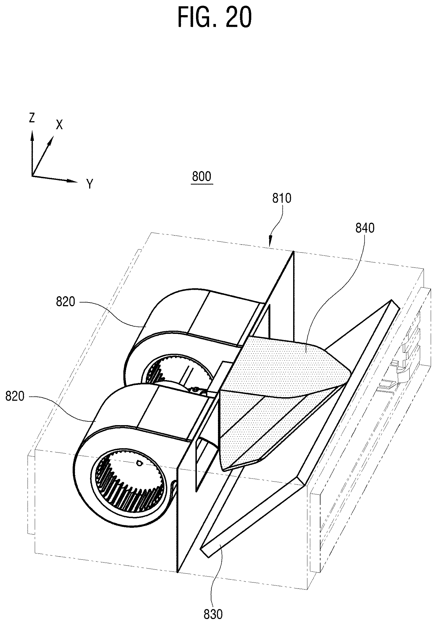
[0142] FIG. 20 is a perspective view showing that a guide member having a predetermined volume is installed in an indoor unit.
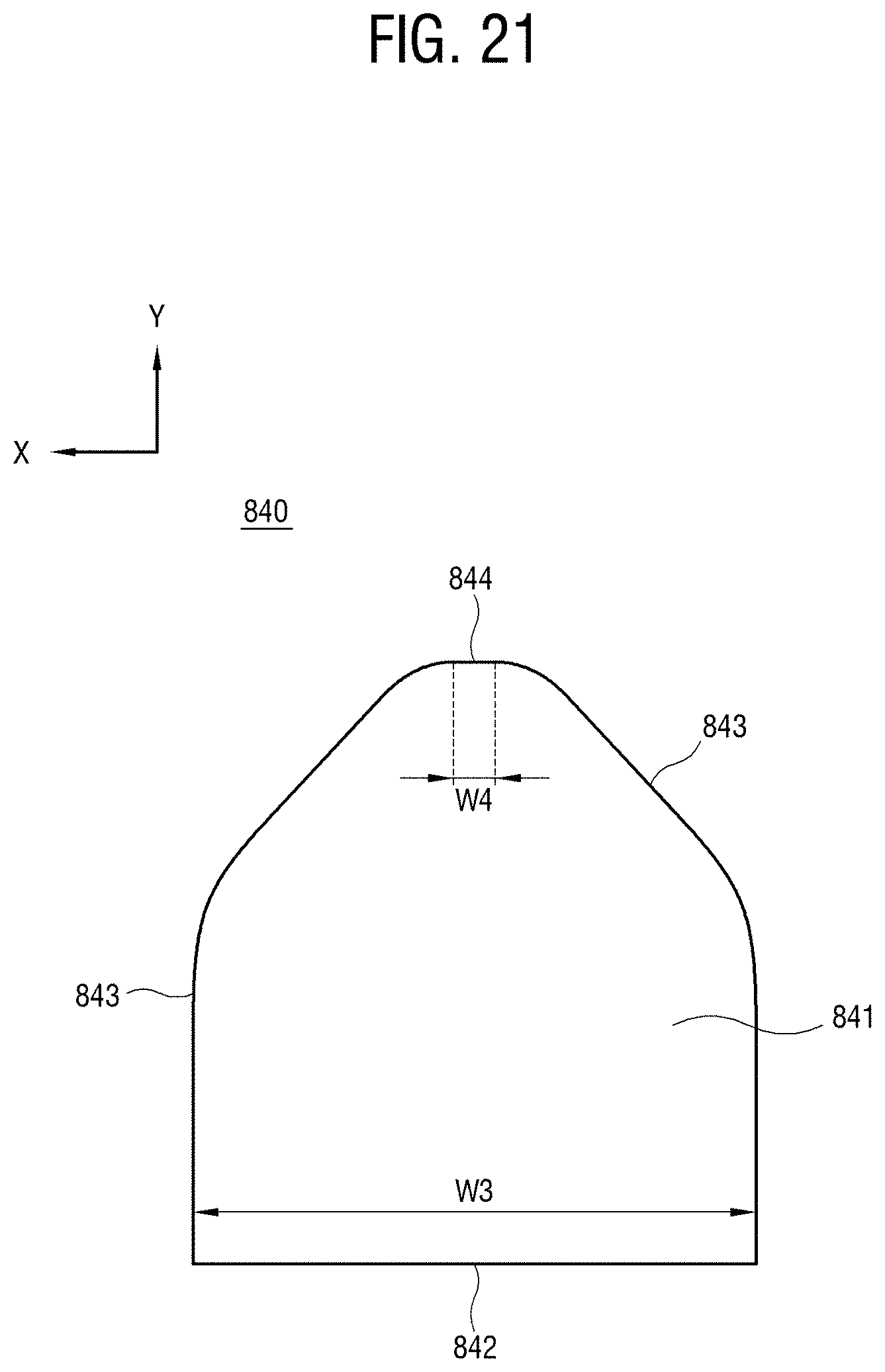
[0143] FIG. 21 is a plan view of the guide member of FIG. 20, viewed from above.
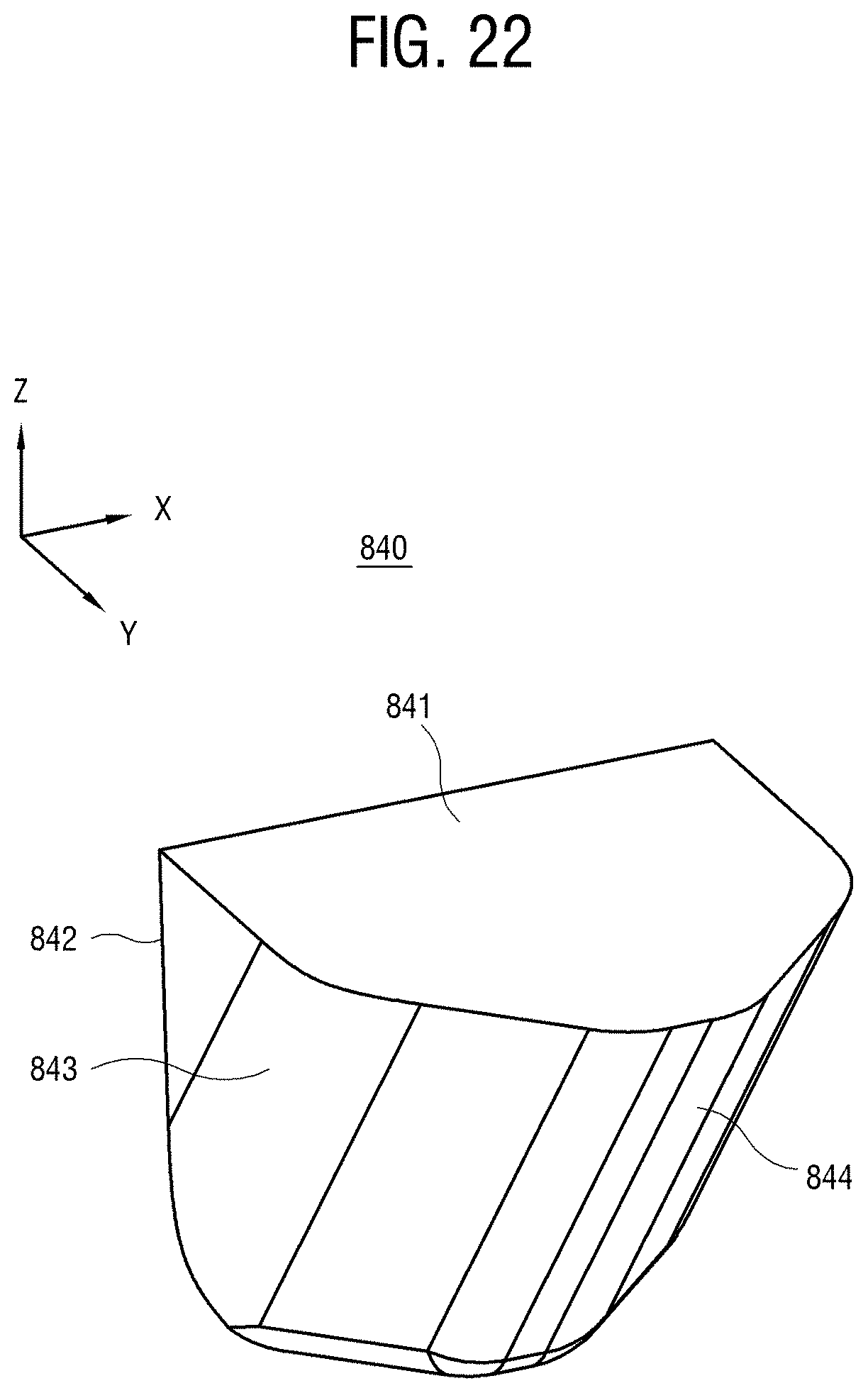
[0144] FIG. 22 is a perspective view of the guide member of FIG. 20.
[0145] As shown in FIGS. 20, 21 and 22, an indoor unit 800 includes a main housing 810, a plurality of air-blowing unit 820, a heat exchanger 830, and a guide member 840. The main housing 810, the plurality of air-blowing unit 820, and the heat exchanger 830 are substantially the same as those of the foregoing embodiments.
[0146] The guide member 840 according to this embodiment includes a guide-member main body 841 forming a main body of the guide member 840. The guide-member main body 841 includes a guide-member backward surface 842 facing the air-blowing unit 820, a guide-member front-end surface 844 facing the heat exchanger 830, and a pair of guide-member lateral surfaces 843 provided between the guide-member backward surface 842 and the guide-member front-end surface 844.
[0147] The width W3 of the guide-member backward surface 842 and the width W4 of the guide-member front-end surface 844 are set to satisfy W3>W4, and therefore a distance between the guide-member lateral surfaces 843 provided at left and right sides of the guide-member main body 841 is generally decreased as going in the direction of Y. Whereas the guide-member lateral surfaces of the foregoing embodiment (see `743` in FIGS. 18 and FIG. 19) is curved having a gentle curvature at a position near the guide-member front-end surface 844, the guide-member lateral surface 843 according to this embodiment is bent between the guide-member backward surface 842 and the guide-member front-end surface 844.
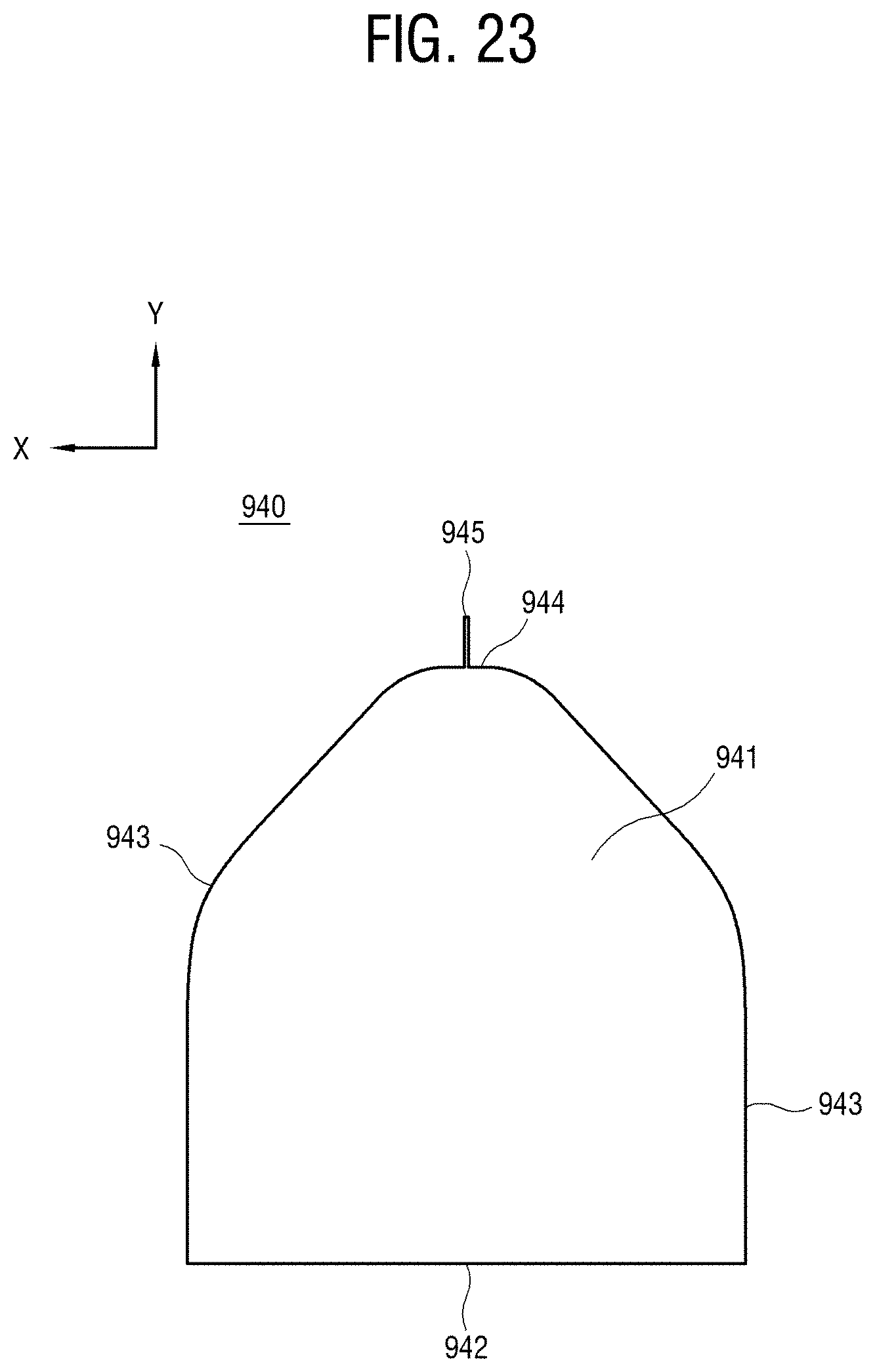
[0148] FIG. 23 is a plan view of the guide member of FIG. 20 with a fin.
[0149] FIG. 24 is a perspective view of the guide member of FIG. 23.
[0150] As shown in FIGS. 23 and 24, a guide member 940 includes a guide-member main body 941 forming a main body of the guide member 940. The guide-member main body 941 includes a guide-member backward surface 942 facing the air-blowing unit, a guide-member front-end surface 944 facing the heat exchanger, and a pair of guide-member lateral surfaces 943 between the guide-member backward surface 942 and the guide-member front-end surface 944. According to this embodiment, the guide member 940 basically has the same structure as the guide member (see `840` in FIGS. 21 and 22) of the foregoing embodiment, and additionally includes a fin 945.
[0151] The fin 945 protrudes from the guide-member front-end surface 944 toward the heat exchanger, and is extended along the plate surface of the heat exchanger. The fin 945 has an effect on preventing two flows of air moving as attached to one pair of guide-member lateral surfaces 943 from swirling between the guide-member front-end surface 944 and the heat exchanger.
[0152] Below, experimental results about speed of fluid will be described with respect to a case where the guide member is shaped as shown in FIG. 10 and a case where the guide member is shaped as shown in FIG. 18.
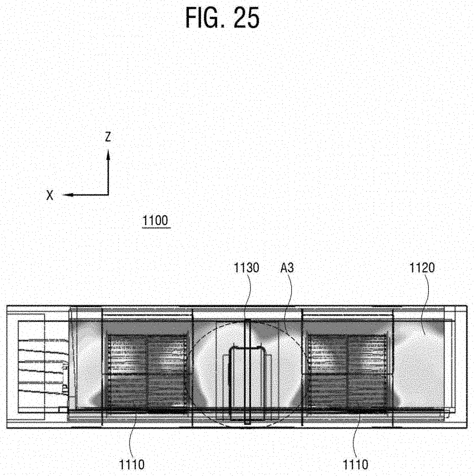
[0153] FIG. 25 illustrates a colorful speed-distribution of a moving fluid measured in an indoor unit with the guide member of FIG. 10.
[0154] As shown in FIG. 25, in an indoor unit 1100 including a plurality of air-blowing unit 1110, a heat exchanger 1120, and a guide member 1130, speed of fluid may be measured according to regions on the surface of the heat exchanger 1120 and represented as a color distribution. Here, the indoor unit 1100 is seen through from the back side. The guide member 1130 is provided in a middle region A3 between a plurality of air-blowing units 1110. In this color distribution, faster speed of fluid is represented with a color inclining to red, and slower speed of fluid is represented with a color inclining to blue.
[0155] In the indoor unit 1100 including a relatively narrow guide member 1130, the region of the air-blowing unit 1110 includes a lot of red but the middle region A3 includes a lot of blue, green and yellow. In other words, this color distribution shows that the speed of fluid in the middle region A3 is slower than that in the other regions except the middle region A3.
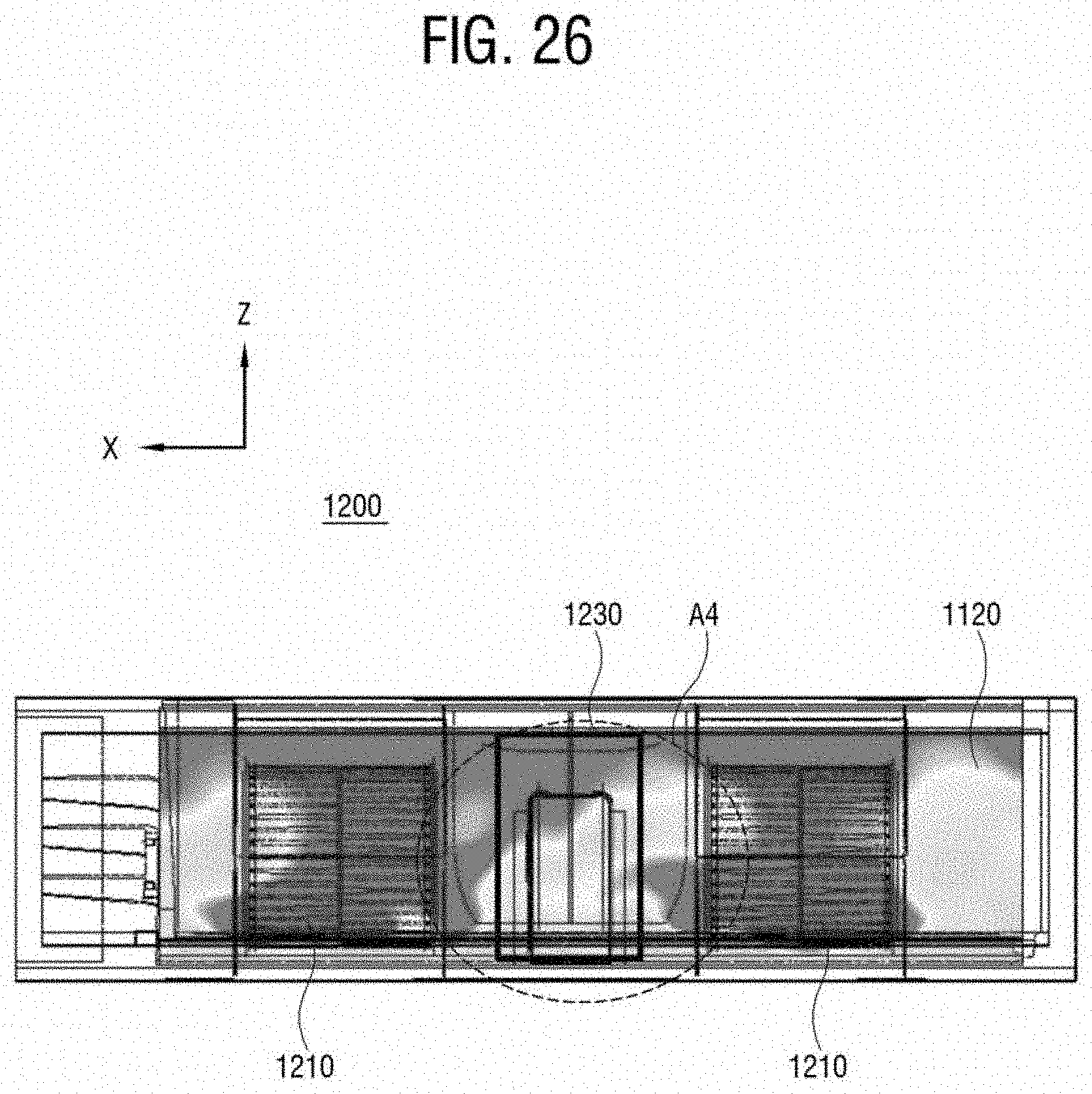
[0156] FIG. 26 illustrates a colorful speed-distribution of a moving fluid measured in an indoor unit with the guide member of FIG. 18.
[0157] As shown in FIG. 26, in an indoor unit 1100 including a plurality of air-blowing unit 1210, a heat exchanger 1220, and a guide member 1230, speed of fluid may be measured according to regions on the surface of the heat exchanger 1220 and represented as a color distribution. In this embodiment, the guide member 1230 has a wider width than the guide member (see `1130` in FIG. 18) in the foregoing embodiment.
[0158] In comparison between the results of this embodiment and the results of the foregoing embodiment, it will be appreciated that blue, green and yellow included in the middle region A4 in this embodiment are relatively decreased, but red is increased. In other words, the guide member 1230 having a relatively large volume enhances the speed of air flowing toward the region of the heat exchanger 1220 corresponding to the middle region A4. Nevertheless, the foregoing embodiment may be effective when the indoor unit has a relatively narrow width or inner space, and thus selectively applied according to the design of the indoor unit.
[0159] Meanwhile, the guide member having a predetermined volume to have the Coand{hacek over (a)} effect does not need to be placed in the middle region between the plurality of air-blowing units. Below, it will be described that the guide member is placed in not the middle region but another position.
[0160] FIG. 27 is a plan view showing that lateral guide members are arranged at lateral sides of a front accommodating portion in an indoor unit.
[0161] As shown in FIG. 27, an indoor unit 1300 includes a main housing 1310, a plurality of air-blowing units 1321 and 1322, a heat exchanger 1330, and a guide member 1340. The guide member 1340 is placed in a middle region between a plurality of air-blowing units 1321 and 1322 in the front accommodating portion. In other words, when a first air-blowing unit 1321 is placed at the left side of the rear accommodating portion in FIG. 27 and a second air-blowing unit 1322 is placed at the right side, the guide member 1340 is placed at the right side of the first air-blowing unit 1321 and at the left side of the second air-blowing unit 1322 in the front accommodating portion. This configuration is substantially the same as those of the foregoing embodiments.
[0162] Here, the indoor unit 1300 according to this embodiment further includes one or more lateral guide members 1351 and 1352 respectively installed in the outmost regions at the opposite sides of the front accommodating portion and guiding air to flow. In other words, the indoor unit 1300 may additionally include a first lateral guide member 1351 extended from a left wall of the front accommodating portion in the main housing 1310 along an air-flowing direction, and a second lateral guide member 1352 extended from a right wall of the front accommodating portion along the air-flowing direction. The lateral guide members 1351 and 1352 may be formed integrally with the main housing 1310, or may be provided as separate members and coupled to the inside of the main housing 1310.
[0163] Each of the lateral guide members 1351 and 1352 may have a rear-side width close to the air-blowing units 1321 and 1322 and a front-side width close to the heat exchanger 1330, in which the rear-side width is wider than the front-side width. Further, each width of the lateral guide members 1351 and 1352 may become narrower as closer to the heat exchanger 1330. In other words, the closer the heat exchanger 1330, the shorter the distance between the side of the front accommodating portion to which each of the lateral guide members 1351 and 1352 is coupled and each side of the lateral guide members 1351 and 1352 with which air meets. Therefore, the closer the heat exchanger 1330, the wider the channel for air discharged from each of the air-blowing units 1321 and 1322.
[0164] When air discharged from each of the air-blowing units 1321 and 1322 meets the lateral guide members 1351 and 1352, the air moves as attached to the lateral guide members 1351 and 1352 based on the Coand{hacek over (a)} effect. Therefore, the speed of fluid is enhanced at the left and right sides in the front accommodating portion.
[0165] Although a few embodiments have been shown and described, it will be appreciated by those skilled in the art that changes may be made in these embodiments without departing from the principles and spirit of the invention, the scope of which is defined in the appended claims and their equivalents.
* * * * *
D00000
D00001
D00002
D00003
D00004
D00005
D00006
D00007
D00008
D00009
D00010
D00011
D00012

D00013
D00014
D00015
D00016

D00017
D00018
D00019
D00020
D00021
D00022
D00023
D00024

D00025
D00026
D00027

XML
uspto.report is an independent third-party trademark research tool that is not affiliated, endorsed, or sponsored by the United States Patent and Trademark Office (USPTO) or any other governmental organization. The information provided by uspto.report is based on publicly available data at the time of writing and is intended for informational purposes only.
While we strive to provide accurate and up-to-date information, we do not guarantee the accuracy, completeness, reliability, or suitability of the information displayed on this site. The use of this site is at your own risk. Any reliance you place on such information is therefore strictly at your own risk.
All official trademark data, including owner information, should be verified by visiting the official USPTO website at www.uspto.gov. This site is not intended to replace professional legal advice and should not be used as a substitute for consulting with a legal professional who is knowledgeable about trademark law.