A method for simulating the discontinuity of the hydraulic fracture wall in fractured reservoirs
Zhao; Jinzhou ; et al.
U.S. patent application number 16/929108 was filed with the patent office on 2020-11-05 for a method for simulating the discontinuity of the hydraulic fracture wall in fractured reservoirs. This patent application is currently assigned to SOUTHWEST PETROLEUM UNIVERSITY. The applicant listed for this patent is SOUTHWEST PETROLEUM UNIVERSITY. Invention is credited to Yongquan Hu, Ran Lin, Lan Ren, Qiang Wang, Chaoneng Zhao, Jin Zhao, Jinzhou Zhao.
| Application Number | 20200347721 16/929108 |
| Document ID | / |
| Family ID | 1000004990304 |
| Filed Date | 2020-11-05 |


View All Diagrams
| United States Patent Application | 20200347721 |
| Kind Code | A1 |
| Zhao; Jinzhou ; et al. | November 5, 2020 |
A method for simulating the discontinuity of the hydraulic fracture wall in fractured reservoirs
Abstract
The invention discloses a method for simulating the discontinuity of the hydraulic fracture wall in fractured reservoirs, comprising the following steps: establish a physical model of the natural fracture; establish a hydraulic fracture propagation calculation equation; establish a natural fracture failure model, calculate the natural fracture aperture, and then calculate the natural fracture permeability, and finally convert the natural fracture permeability into the permeability of the porous medium; couple the hydraulic fracture propagation calculation equation with the permeability of the porous medium through the fracture propagation criterion and the fluid loss to obtain a pore elastic model of the coupled natural fracture considering the influence of the natural fracture; work out the stress and displacement distribution of the hydraulic fracture wall with the pore elastic model of the coupled natural fracture, and analyze the offset and discontinuity of the hydraulic fracture wall according to the displacement.
| Inventors: | Zhao; Jinzhou; (CHENGDU CITY, CN) ; Wang; Qiang; (CHENGDU CITY, CN) ; Hu; Yongquan; (CHENGDU CITY, CN) ; Ren; Lan; (CHENGDU CITY, CN) ; Zhao; Chaoneng; (CHENGDU CITY, CN) ; Zhao; Jin; (CHENGDU CITY, CN) ; Lin; Ran; (CHENGDU CITY, CN) | ||||||||||
| Applicant: |
|
||||||||||
|---|---|---|---|---|---|---|---|---|---|---|---|
| Assignee: | SOUTHWEST PETROLEUM
UNIVERSITY CHENGDU CITY CN |
||||||||||
| Family ID: | 1000004990304 | ||||||||||
| Appl. No.: | 16/929108 | ||||||||||
| Filed: | July 15, 2020 |
| Current U.S. Class: | 1/1 |
| Current CPC Class: | E21B 49/003 20130101; E21B 49/005 20130101; E21B 47/003 20200501 |
| International Class: | E21B 49/00 20060101 E21B049/00; E21B 47/003 20060101 E21B047/003 |
Foreign Application Data
| Date | Code | Application Number |
|---|---|---|
| Dec 4, 2019 | CN | 201911225898.1 |
Claims
1. A method for simulating the discontinuity of the hydraulic fracture wall in fractured reservoirs, comprising the following steps: acquire geological parameters of the fractured reservoir, and establish a physical model of the natural fracture based on the fracture continuum model according to the length, width, height and other physical conditions of the natural fracture; establish a hydraulic fracture propagation calculation equation on the basis of the in-fracture flow equation, fluid loss equation, width equation and material balance equation; establish a natural fracture failure model according to the Mohr-Coulomb rule, work out the natural fracture aperture according to the natural fracture failure model, calculate the natural fracture permeability based on the natural fracture aperture, and convert the fracture permeability into the permeability of the porous medium with the fracture continuum model; couple the hydraulic fracture propagation calculation equation with the permeability of the porous medium through the fracture propagation criterion and the fluid loss to obtain a pore elastic model of the coupled natural fracture considering the influence of the natural fracture; and work out the stress and displacement distribution of the hydraulic fracture wall with the pore elastic model of the coupled natural fracture, and analyze the offset and discontinuity of the hydraulic fracture wall according to the displacement.
2. The method for simulating the discontinuity of the hydraulic fracture wall in fractured reservoirs according to claim 1, wherein the geological parameters are obtained by logging or fracturing, specifically including initial aperture of natural fracture, matrix initial permeability, initial porosity, elastic modulus and Poisson's ratio.
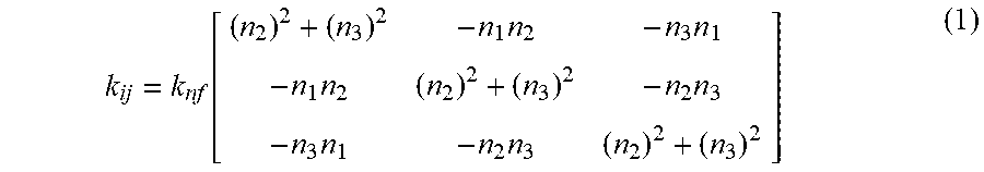
3. The method for simulating the discontinuity of the hydraulic fracture wall in fractured reservoirs according to claim 1, wherein the fracture continuum model is as follows: k ij = k nf [ ( n 2 ) 2 + ( n 3 ) 2 - n 1 n 2 - n 3 n 1 - n 1 n 2 ( n 2 ) 2 + ( n 3 ) 2 - n 2 n 3 - n 3 n 1 - n 2 n 3 ( n 2 ) 2 + ( n 3 ) 2 ] ( 1 ) ##EQU00011## Where, k.sub.ij is the matrix permeability tensor, in m.sup.2; k.sub.nf is the natural fracture permeability, in m.sup.2; n.sub.1, n.sub.2 and n.sub.3 are calculated as follows: n 1 = cos ( .pi. 180 ) sin ( .xi. .pi. 180 ) n 2 = cos ( .pi. 180 ) cos ( .xi. .pi. 180 ) n 3 = - sin ( .pi. 180 ) ( 2 ) ##EQU00012## Where, c is the dip angle, in .degree.; .xi. is the approaching angle, in .degree.; The natural fracture permeability k.sub.nf is calculated as follows: k nf = w NF 3 12 d ( 3 ) ##EQU00013## Where, w.sub.NF is the natural fracture aperture, in m; d is the natural fracture spacing, in m.
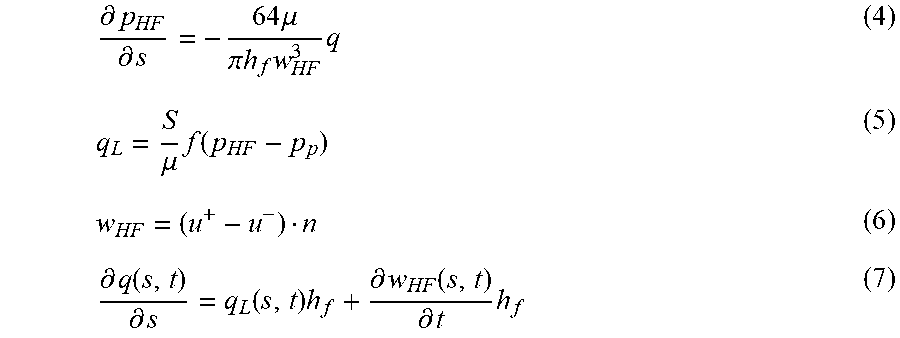
4. The method for simulating the discontinuity of the hydraulic fracture wall in fractured reservoirs according to claim 3, wherein the hydraulic fracture propagation calculation equation is worked out by substituting the in-fracture flow equation, fluid loss equation and width equation into the material balance equation; the substitution of in-fracture flow equation, fluid loss equation, width equation and the material balance equation are as follows: .differential. p HF .differential. s = - 64 .mu. .pi. h f w HF 3 q ( 4 ) q L = S .mu. f ( p HF - p p ) ( 5 ) w HF = ( u + - u - ) n ( 6 ) .differential. q ( s , t ) .differential. s = q L ( s , t ) h f + .differential. w HF ( s , t ) .differential. t h f ( 7 ) ##EQU00014## Where, .differential. is the partial differential symbol; p.sub.HF is the pressure in the fracture, in Pa; s is the coordinate of fracture length direction, in m; .mu. is the fluid viscosity, in mPas; h.sub.f is the hydraulic fracture height, in m; w.sub.HF is the hydraulic fracture aperture, in m; q is the flow in the hydraulic fracture, in m.sup.3/s; q.sub.L is the fracturing fluid loss rate, in m/s; S is the fracturing fluid loss area, in m.sup.2; f is the fluid loss coefficient, in 1/m; p.sub.p is the reservoir pore pressure, in MPa; u.sup.+ and u.sup.- are displacements on the left and right sides of the hydraulic fracture, in m; n is the unit normal vector on the hydraulic fracture surface, dimensionless; t is the fracturing time, in min.
5. The method for simulating the discontinuity of the hydraulic fracture wall in fractured reservoirs according to claim 4, wherein the natural fracture failure model is as follows: .sigma..sub..tau.>.tau..sub.0+tan(.phi..sub.basic)(.sigma..sub.n-p.sub- .NF) (8) p.sub.NF.gtoreq..sigma..sub.n+K.sub.t (9) w.sub.NF=a.sub.0+a.sub.NFT+a.sub.NFS (10) Where, .sigma..sub..tau. is the shear stress on the natural fracture wall, in MPa; .tau..sub.0 is the natural fracture cohesion, in MPa; .phi..sub.basic is the basic friction angle, in .degree.; .sigma..sub.n is the normal stress on the natural fracture surface, in MPa; p.sub.NF is the fluid pressure in the natural fracture, in MPa; K.sub.t is the tensile strength of the natural fracture, in MPa; a.sub.0 is the initial aperture of the natural fracture, in m; a.sub.NFT is the extensional aperture of the natural fracture, in m; a.sub.NFS is the shear aperture of the natural fracture, in m.
6. The method for simulating the discontinuity of the hydraulic fracture wall in fractured reservoirs according to claim 5, wherein the basic friction angle is within a range from 30.degree. to 40.degree..
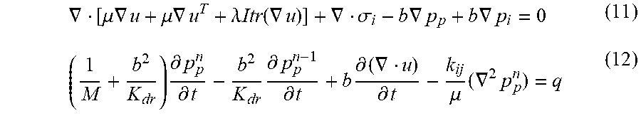
7. The method for simulating the discontinuity of the hydraulic fracture wall in fractured reservoirs according to claim 5, wherein the pore elastic model of the coupled natural fracture is as follows: .gradient. [ .mu. .gradient. u + .mu. .gradient. u T + .lamda. Itr ( .gradient. u ) ] + .gradient. .sigma. i - b .gradient. p p + b .gradient. p i = 0 ( 11 ) ( 1 M + b 2 K dr ) .differential. p p n .differential. t - b 2 K dr .differential. p p n - 1 .differential. t + b .differential. ( .gradient. u ) .differential. t - k ij .mu. ( .gradient. 2 p p n ) = q ( 12 ) ##EQU00015## Where, .gradient. is the Laplacian operator; u is the displacement tensor, in m; T is the matrix transpose; .lamda. is the lame constant, in MPa; Itr is the integral symbol; .sigma..sub.i is the stress tensor, in MPa; b is the Biot effective coefficient, dimensionless; p.sub.i is the initial pore pressure, in MPa; M is the Biot modulus, in MPa; K.sub.dr is the bulk modulus in the drainage process, in MPa.
Description
TECHNICAL FIELD
[0001] The present invention relates to the technical field of hydraulic fractures, in particular to a method for simulating the discontinuity of the hydraulic fracture wall in fractured reservoirs.
DESCRIPTION OF PRIOR ART
[0002] For the study of hydraulic fracturing technology for unconventional reservoirs, most researchers consider the original porous elastic formation as elastic formation, and only consider the flow in the fracture as the fluid flow, ignoring the flow in the pore. This consideration is based on elastic mechanics, but it is far from the actual conditions of unconventional reservoirs. Therefore, the hydraulic fracture wall obtained in most studies is smooth and continuous. However, it can be seen from many experiments (Wang Yue. Fracture simulation based on large hydraulic fracturing experiment system in laboratory [J]. Progress in Geophysics, 2017, 32 (1): 408-413; Zhang Jian, Zhang Guoxiang, Li Liang, et al. Study on simulation and experiment of shale hydraulic fracturing [J]. Journal of Hefei University of Technology (Natural Science), 2019, 42 (4): 541-545) that the fracture wall formed after the hydraulic fracturing of the reservoir rock is not smooth and continuously distributed, but is uneven and discontinuous. This phenomenon is ignored in most studies, but the discontinuity of the hydraulic fracture wall has a great influence on the proppant migration. Therefore, conventional methods can no longer accurately simulate the actual conditions of hydraulic fractures in the fracturing process.
[0003] Furthermore, most of the current studies focus on the propagation path of hydraulic fractures in unconventional reservoirs and the intersection between hydraulic fractures and natural fractures (Li Xiao, He Jianming, Yin Chao, et al. Characteristics of the shale bedding planes and their control on hydraulic fracturing [J]. Natural Gas Geoscience, 2019, 40 (3): 653-660; Chen X, Li Y, Zhao J, Xu W, Fu D. Numerical investigation for simultaneous growth of hydraulic fractures in multiple horizontal wells[J]. Journal of Natural Gas Science and Engineering, 2018, 51:44-52). The purpose is to study the mechanism of the intersection between hydraulic fractures and natural fractures, and then to simulate and predict the network forming capacity and the stimulated volume of reservoirs during fracturing. However, due to the limitation of the calculation method, when the number of natural fractures increases, the calculation time increases exponentially and the computer is required to have higher performance and configuration (Roussel, N. P. and Sharma, M. M. Role of Stress Reorientation in the Success of Refracture Treatments in Tight Gas Sands [J]. SPE Prod & Oper, 2012, 27 (4): 346-355). Therefore, the original simulation method is no longer applicable to the field engineering practice. In addition, because the reservoir is considered as an elastomer rather than a porous elastic medium, there will be a large error in the calculation results of fluid loss and reservoir stress, which is also a disadvantage of the conventional method (Gao Q, Ghassemi A. Pore pressure and stress distributions around a hydraulic fracture in heterogeneous rock [J]. Rock Mechanics and Rock Engineering, 2017, 50(12), 3157-3173).
SUMMARY OF THE INVENTION
[0004] In view of the above problems, the present invention aims to provide a method for simulating the discontinuity of the hydraulic fracture wall in fractured reservoirs. Specifically, analyze the effects of natural fracture, hole elasticity and hydraulic drive, and the coupling effect between the fluid and the geologic stress in the fracturing process, then establish a new mathematical model based on the Biot theory, fluid-solid coupling principle, finite difference theory and multiphase seepage principle to simulate the multi-cluster hydraulic fracture propagation and analyze the hydraulic fracture wall discontinuity; use the mathematical model to predict the offset and uneven propagation of hydraulic fractures under the influence of the uneven stress in the dynamic fracturing process with different parameters in combination with the construction parameters, initial conditions and boundary conditions, so as to analyze the roughness of the fracture wall by analyzing the discontinuity of the fracture wall. Finally, it provides a guidance and reference for the proppant migration in hydraulic fractures.
[0005] The technical solution of the present invention is as follows:
[0006] A method for simulating the discontinuity of the hydraulic fracture wall in fractured reservoirs, comprising the following steps:
[0007] Acquire geological parameters of the fractured reservoir, and establish a physical model of the natural fracture based on the fracture continuum model according to the length, width, height and other physical conditions of the natural fracture;
[0008] Establish a hydraulic fracture propagation calculation equation on the basis of the in-fracture flow equation, fluid loss equation, width equation and material balance equation;
[0009] Establish a natural fracture failure model according to the Mohr-Coulomb rule, work out the natural fracture aperture according to the natural fracture failure model, calculate the natural fracture permeability based on the natural fracture aperture, and convert the fracture permeability into the permeability of the porous medium with the fracture continuum model;
[0010] Couple the hydraulic fracture propagation calculation equation with the permeability of the porous medium through the fracture propagation criterion and the fluid loss to obtain a pore elastic model of the coupled natural fracture considering the influence of the natural fracture;
[0011] Work out the stress and displacement distribution of the hydraulic fracture wall with the pore elastic model of the coupled natural fracture, and analyze the offset and discontinuity of the hydraulic fracture wall according to the displacement.
[0012] Further, the geological parameters are obtained by logging or fracturing, specifically including initial aperture of natural fracture, matrix initial permeability, initial porosity, elastic modulus and Poisson's ratio.
[0013] Further, the fracture continuum model is as follows:
k ij = k nf [ ( n 2 ) 2 + ( n 3 ) 2 - n 1 n 2 - n 3 n 1 - n 1 n 2 ( n 2 ) 2 + ( n 3 ) 2 - n 2 n 3 - n 3 n 1 - n 2 n 3 ( n 2 ) 2 + ( n 3 ) 2 ] ( 1 ) ##EQU00001##
Where,
[0014] k.sub.ij is the matrix permeability tensor, in m.sup.2; k.sub.nf is the natural fracture permeability, in m.sup.2; n.sub.1, n.sub.2 and n.sub.3 are calculated as follows:
n 1 = cos ( .pi. 180 ) sin ( .xi. .pi. 180 ) n 2 = cos ( .pi. 180 ) cos ( .xi. .pi. 180 ) n 3 = - sin ( .pi. 180 ) ( 2 ) ##EQU00002##
Where,
[0015] c is the dip angle, in .degree.; .xi. is the approaching angle, in .degree.; The natural fracture permeability k.sub.nf is calculated as follows:
k nf = w NF 3 12 d ( 3 ) ##EQU00003##
Where,
[0016] w.sub.NF is the natural fracture aperture, in m; d is the natural fracture spacing, in m.
[0017] Further, the hydraulic fracture propagation calculation equation is worked out by substituting the in-fracture flow equation, fluid loss equation and width equation into the material balance equation; the substitution of in-fracture flow equation, fluid loss equation, width equation and the material balance equation are as follows:
.differential. p HF .differential. s = - 64 .mu. .pi. h f w HF 3 q ( 4 ) q L = S .mu. f ( p HF - p p ) ( 5 ) w HF = ( u + - u - ) n ( 6 ) .differential. q ( s , t ) .differential. s = q L ( s , t ) h f + .differential. w HF ( s , t ) .differential. t h f ( 7 ) ##EQU00004##
Where,
[0018] .differential. is the partial differential symbol; p.sub.HF is the pressure in the fracture, in Pa; s is the coordinate of fracture length direction, in m; .mu. is the fluid viscosity, in mPas; h.sub.f is the hydraulic fracture height, in m; w.sub.HF is the hydraulic fracture aperture, in m; q is the flow in the hydraulic fracture, in m.sup.3/s; q.sub.L is the fracturing fluid loss rate, in m/s; S is the fracturing fluid loss area, in m.sup.2; f is the fluid loss coefficient, in 1/m; p.sub.p is the reservoir pore pressure, in MPa; u.sup.+ and u.sup.- are displacements on the left and right sides of the hydraulic fracture, in m; n is the unit normal vector on the hydraulic fracture surface, dimensionless; t is the fracturing time, in min.
[0019] Further, the natural fracture failure model is as follows:
.sigma..sub..tau.>.tau..sub.0+tan(.phi..sub.basic)(.sigma..sub.n-p.su- b.NF) (8)
p.sub.NF.gtoreq..sigma..sub.n+K.sub.t (9)
w.sub.NF=a.sub.0+a.sub.NFT+a.sub.NFS (10)
Where,
[0020] .sigma..sub..tau. is the shear stress on the natural fracture wall, in MPa; .tau..sub.0 is the natural fracture cohesion, in MPa; .phi..sub.basic is the basic friction angle, in .degree.; .sigma..sub.n is the normal stress on the natural fracture surface, in MPa; p.sub.NF is the fluid pressure in the natural fracture, in MPa; K.sub.t is the tensile strength of the natural fracture, in MPa; a.sub.0 is the initial aperture of the natural fracture, in m; a.sub.NFT is the extensional aperture of the natural fracture, in m; a.sub.NFS is the shear aperture of the natural fracture, in m.
[0021] Further, the basic friction angle is within a range from 30.degree. to 40.degree..
[0022] Further, the pore elastic model of the coupled natural fracture is as follows:
.gradient. [ .mu. .gradient. u + .mu. .gradient. u T + .lamda. Itr ( .gradient. u ) ] + .gradient. .sigma. i - b .gradient. p p + b .gradient. p i = 0 ( 11 ) ( 1 M + b 2 K dr ) .differential. p p n .differential. t - b 2 K dr .differential. p p n - 1 .differential. t + b .differential. ( .gradient. u ) .differential. t - k ij .mu. ( .gradient. 2 p p n ) = q ( 12 ) ##EQU00005##
Where,
[0023] .gradient. is the Laplacian operator; u is the displacement tensor, in m; T is the matrix transpose; .lamda. is the lame constant, in MPa; Itr is the integral symbol; .sigma..sub.i is the stress tensor, in MPa; b is the Biot effective coefficient, dimensionless; p.sub.i is the initial pore pressure, in MPa; M is the Biot modulus, in MPa; K.sub.dr is the bulk modulus in the drainage process, in MPa.
[0024] Compared with the prior art, the present invention has the following advantages:
[0025] In the process of the staged multi-cluster fracturing in the unconventional reservoirs, the present invention considers the effects of natural fractures on reservoir fluid flow, hydraulic fracture propagation, and stress distribution, and also considers the pore elastic effect of the reservoir, so as to accurately calculate the displacement and discontinuity of the hydraulic fracture wall with different number of fracture clusters and different fracturing time. In addition, when the number of natural fractures increases in multiples, the present invention directly calculates the matrix permeability tensor of natural fractures by the fracture continuum model, which solves the shortcoming in the prior art that each natural fracture needs to be calculated separately, causing heavy calculation amount. In summary, the present invention has an important role in the analysis of the proppant migration in hydraulic fracturing and the fracture conductivity after fracturing, and also has reference significance for the development of oil and gas fields and the enrichment of basic theories of hydraulic fracturing.
BRIEF DESCRIPTION OF THE DRAWINGS
[0026] In order to explain the embodiments of the present invention or the technical solutions in the prior art more clearly, the following will make a brief introduction to the drawings needed in the description of the embodiments or the prior art. Obviously, the drawings in the following description are merely some embodiments of the present invention. For those of ordinary skill in the art, other drawings can be obtained based on these drawings without any creative effort.
[0027] FIG. 1 is a schematic diagram of physical model of natural fracture in the present invention.
[0028] FIG. 2 is a cloud chart of stress distribution after fracturing in Embodiment 1.
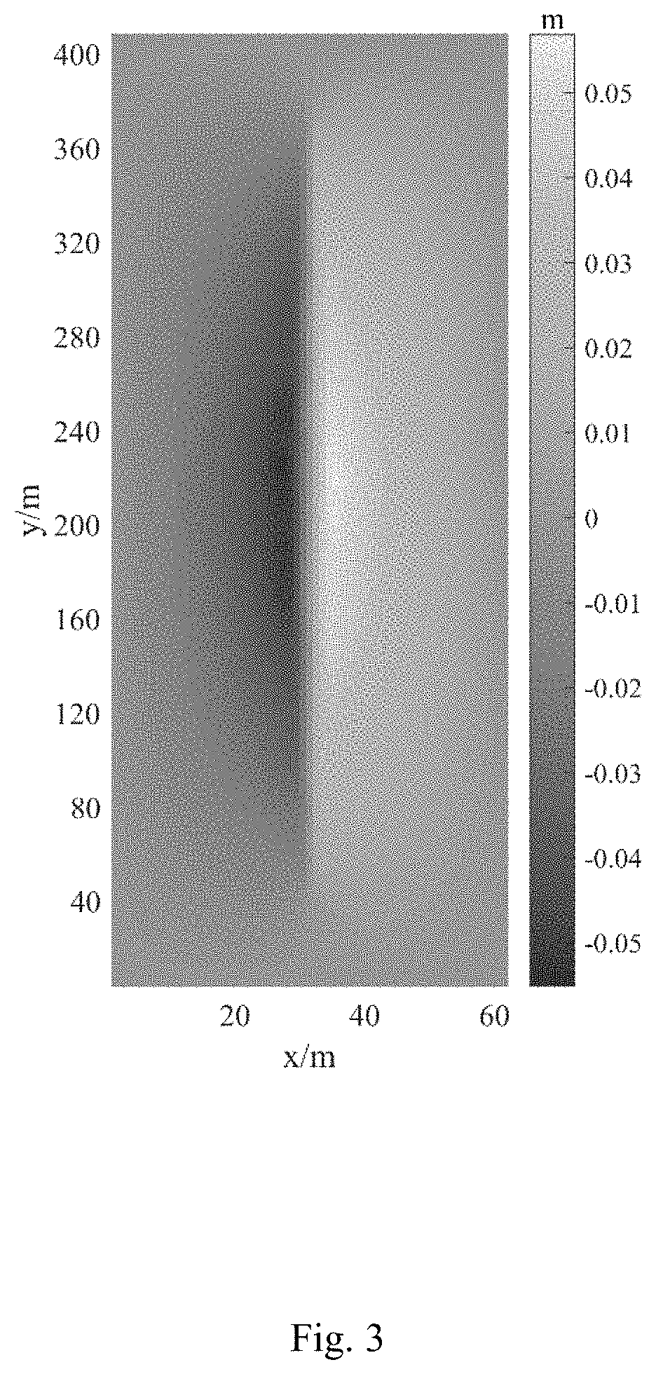
[0029] FIG. 3 is a cloud chart of displacement distribution after fracturing in Embodiment 1.
[0030] FIG. 4 is a schematic diagram of discontinuous distribution of the hydraulic fracture wall in Embodiment 1.
DETAILED DESCRIPTION OF THE PREFERRED EMBODIMENTS
[0031] The present invention is further described with reference to the drawings and embodiments. It should be noted that the embodiments in this application and the technical features in the embodiments can be combined with each other without conflict.
[0032] A method for simulating the discontinuity of the hydraulic fracture wall in fractured reservoirs, comprising the following steps:
[0033] Firstly, acquire geological parameters of the fractured reservoir, and establish a physical model of the natural fracture based on the fracture continuum model according to the length, width, height and other physical conditions of the natural fracture; the geological parameters are obtained by logging or fracturing, specifically including initial aperture of natural fracture, matrix initial permeability, initial porosity, elastic modulus and Poisson's ratio. The fracture continuum model is as follows:
k ij = k nf [ ( n 2 ) 2 + ( n 3 ) 2 - n 1 n 2 - n 3 n 1 - n 1 n 2 ( n 2 ) 2 + ( n 3 ) 2 - n 2 n 3 - n 3 n 1 - n 2 n 3 ( n 2 ) 2 + ( n 3 ) 2 ] ( 1 ) ##EQU00006##
Where,
[0034] k.sub.ij is the matrix permeability tensor, in m.sup.2; k.sub.nf is the natural fracture permeability, in m.sup.2; n.sub.1, n.sub.2 and n.sub.3 are calculated as follows:
n 1 = cos ( .pi. 180 ) sin ( .xi. .pi. 180 ) n 2 = cos ( .pi. 180 ) cos ( .xi. .pi. 180 ) n 3 = - sin ( .pi. 180 ) ( 2 ) ##EQU00007##
Where,
[0035] c is the dip angle, in .degree.; .xi. is the approaching angle, in .degree.;
[0036] The natural fracture permeability k.sub.nf is calculated as follows:
k nf = w NF 3 12 d ( 3 ) ##EQU00008##
Where,
[0037] w.sub.NF is the natural fracture aperture, in m; d is the natural fracture spacing, in m.
[0038] Secondly, establish the hydraulic fracture propagation calculation equation on the basis of the in-fracture flow equation, fluid loss equation, width equation and material balance equation, and work out it by substituting the flow equation, fluid loss equation and width equation into the material balance equation. The substitution of in-fracture flow equation, fluid loss equation, width equation and the material balance equation are as follows:
.differential. p HF .differential. s = - 64 .mu. .pi. h f w HF 3 q ( 4 ) q L = S .mu. f ( p HF - p p ) ( 5 ) w HF = ( u + - u - ) n ( 6 ) .differential. q ( s , t ) .differential. s = q L ( s , t ) h f + .differential. w HF ( s , t ) .differential. t h f ( 7 ) ##EQU00009##
Where,
[0039] .differential. is the partial differential symbol; p.sub.HF is the pressure in the fracture, in Pa; s is the coordinate of fracture length direction, in m; .mu. is the fluid viscosity, in mPas; h.sub.f is the hydraulic fracture height, in m; w.sub.HF is the hydraulic fracture aperture, in m; q is the flow in the hydraulic fracture, in m.sup.3/s; q.sub.L is the fracturing fluid loss rate, in m/s; S is the fracturing fluid loss area, in m.sup.2; f is the fluid loss coefficient, in 1/m; p.sub.p is the reservoir pore pressure, in MPa; u.sup.+ and u.sup.- are displacements on the left and right sides of the hydraulic fracture, in m; n is the unit normal vector on the hydraulic fracture surface, dimensionless; t is the fracturing time, in min.
[0040] Thirdly, establish the natural fracture failure model according to the Mohr-Coulomb rule, obtain the natural fracture aperture according to the natural fracture failure model, work out the natural fracture permeability based on the natural fracture aperture, and convert the fracture permeability into the permeability of the porous medium by the fracture continuum model. The natural fracture failure model is as follows:
.sigma..sub..tau.>.tau..sub.0+tan(.phi..sub.basic)(.sigma..sub.n-p.su- b.NF) (8)
p.sub.NF.gtoreq..sigma..sub.n+K.sub.t (9)
w.sub.NF=a.sub.0+a.sub.NFT+a.sub.NFS (10)
[0041] Where,
.sigma..sub..tau. is the shear stress on the natural fracture wall, in MPa; .tau..sub.0 is the natural fracture cohesion, in MPa; .phi..sub.basic is the basic friction angle, in .degree.; .sigma..sub.n is the normal stress on the natural fracture surface, in MPa; p.sub.NF is the fluid pressure in the natural fracture, in MPa; K.sub.t is the tensile strength of the natural fracture, in MPa; a.sub.0 is the initial aperture of the natural fracture, in m; a.sub.NFT is the extensional aperture of the natural fracture, in m; a.sub.NFS is the shear aperture of the natural fracture, in m.
[0042] Optionally, the basic friction angle is within a range from 30.degree. to 40.degree..
[0043] Fourthly, couple the hydraulic fracture propagation calculation equation with the permeability of the porous medium through the fracture propagation criterion and the fluid loss to obtain a pore elastic model of the coupled natural fracture considering the influence of the natural fracture. The pore elastic model of the coupled natural fracture is as follows:
.gradient. [ .mu. .gradient. u + .mu. .gradient. u T + .lamda. Itr ( .gradient. u ) ] + .gradient. .sigma. i - b .gradient. p p + b .gradient. p i = 0 ( 11 ) ( 1 M + b 2 K dr ) .differential. p p n .differential. t - b 2 K dr .differential. p p n - 1 .differential. t + b .differential. ( .gradient. u ) .differential. t - k ij .mu. ( .gradient. 2 p p n ) = q ( 12 ) ##EQU00010##
Where,
[0044] .gradient. is the Laplacian operator; u is the displacement tensor, in m; T is the matrix transpose; .lamda. is the lame constant, in MPa; Itr is the integral symbol; .sigma..sub.i is the stress tensor, in MPa; b is the Biot effective coefficient, dimensionless; p.sub.i is the initial pore pressure, in MPa; M is the Biot modulus, in MPa; K.sub.dr is the bulk modulus in the drainage process, in MPa.
[0045] Finally, work out the stress and displacement distribution of the hydraulic fracture wall with the pore elastic model of the coupled natural fracture, and analyze the offset and discontinuity of the hydraulic fracture wall according to the displacement.
Embodiment 1
[0046] A typical unconventional reservoir in a block of Fuling is taken as the fractured reservoir to be simulated. The geological and construction parameters of the block are obtained through field logging and well testing, as shown in Table 1.
TABLE-US-00001 TABLE 1 Geological Parameters and Construction Parameters of Fractured Reservoir to be Simulated Parameters Value Parameters Value Displacement (m.sup.3/h) 11 Natural fracture 0.4 spacing (m) Fluid viscosity 10 Rock compressibil- 4 .times. 10.sup.-3 (MPa S) ity (MPa.sup.-1) Total volume injected 1500 Fluid compressibil- 8 .times. 10.sup.-4 (m.sup.3) ity (MPa.sup.-1) Cluster spacing (m) 10 Natural fracture 35 approaching angle (.degree.) Number of clusters 1 Natural fracture dip 90 angle (.degree.) Model size (H .times. W .times. 40*60*400 Vertical principal 55 L) (m) stress (MPa) Initial pore pressure 35 Horizontal minimum 54 (MPa) principal stress (MPa) Matrix initial 0.01~0.1 Horizontal maximum 60 permeability (mD) principal stress (MPa) Initial porosity of 0.041 Initial aperture of .sup. 10.sup.-4 the reservoir the natural fracture (m) Elastic modulus 3 .times. 10.sup.4 Poisson's ratio 0.2 (MPa)
[0047] Establish a physical model of the natural fracture according to the geological parameters and the length, width, height and other physical conditions of natural fracture, as shown in FIG. 1.
[0048] Work out the natural fracture aperture according to the natural fracture failure model of Equations (8) to (10), and then calculate the natural fracture permeability with Equation (3), and finally convert the natural fracture permeability into the permeability of the porous medium with Equations (1) and (2).
[0049] Substitute Equations (4) to (6) into Equation (7) to obtain the hydraulic fracture propagation calculation equation, and couple the hydraulic fracture propagation calculation equation with the permeability of the porous medium through the fracture propagation criterion and the fluid loss to obtain pore elastic model of the coupled natural fracture considering the influence of the natural fracture.
[0050] Work out the the stress and displacement distribution (as shown in FIG. 3) of hydraulic fracture wall with the pore elastic model of the coupled natural fracture, and analyze the offset and discontinuity of the hydraulic fracture wall according to the displacement. The offset and discontinuity distribution of the hydraulic fracture wall, at 25 minutes, 50 minutes, and 75 minutes of the hydraulic fracturing, are shown in FIG. 4.
[0051] The above are only the preferred embodiments of the present invention, not intended to limit the present invention in any form. Although the present invention has been disclosed as above with the preferred embodiments, it is not intended to limit the present invention. Those skilled in the art, within the scope of the technical solution of the present invention, can use the disclosed technical content to make a few changes or modify the equivalent embodiment with equivalent changes. Within the scope of the technical solution of the present invention, any simple modification, equivalent change and modification made to the above embodiments according to the technical essence of the present invention are still regarded as a part of the technical solution of the present invention.
* * * * *
D00000
D00001
D00002
D00003
D00004


XML
uspto.report is an independent third-party trademark research tool that is not affiliated, endorsed, or sponsored by the United States Patent and Trademark Office (USPTO) or any other governmental organization. The information provided by uspto.report is based on publicly available data at the time of writing and is intended for informational purposes only.
While we strive to provide accurate and up-to-date information, we do not guarantee the accuracy, completeness, reliability, or suitability of the information displayed on this site. The use of this site is at your own risk. Any reliance you place on such information is therefore strictly at your own risk.
All official trademark data, including owner information, should be verified by visiting the official USPTO website at www.uspto.gov. This site is not intended to replace professional legal advice and should not be used as a substitute for consulting with a legal professional who is knowledgeable about trademark law.