Jumper Termination Manifold
ALI; Mohammed Hasan
U.S. patent application number 16/763070 was filed with the patent office on 2020-11-05 for jumper termination manifold. The applicant listed for this patent is Vetco Gray Scandinavia AS. Invention is credited to Mohammed Hasan ALI.
| Application Number | 20200347703 16/763070 |
| Document ID | / |
| Family ID | 1000005018121 |
| Filed Date | 2020-11-05 |


View All Diagrams
| United States Patent Application | 20200347703 |
| Kind Code | A1 |
| ALI; Mohammed Hasan | November 5, 2020 |
JUMPER TERMINATION MANIFOLD
Abstract
The invention relates to a solution that enables the connection of multiple jumpers to a single tie-in hub. The solution concerns a subsea assembly (100) that comprises branched connections for multiple jumpers. The subsea assembly comprises a well multiplier assembly (120) comprising a branched pipe (130), a tie-in hub coupling (140), at least one tie-in hub (150), and a well multiplier assembly connection (155).
| Inventors: | ALI; Mohammed Hasan; (Sandvika, NO) | ||||||||||
| Applicant: |
|
||||||||||
|---|---|---|---|---|---|---|---|---|---|---|---|
| Family ID: | 1000005018121 | ||||||||||
| Appl. No.: | 16/763070 | ||||||||||
| Filed: | November 19, 2018 | ||||||||||
| PCT Filed: | November 19, 2018 | ||||||||||
| PCT NO: | PCT/EP2018/025294 | ||||||||||
| 371 Date: | May 11, 2020 |
| Current U.S. Class: | 1/1 |
| Current CPC Class: | E21B 43/0107 20130101; E21B 43/017 20130101; E21B 43/013 20130101; E21B 21/10 20130101; E21B 41/0007 20130101 |
| International Class: | E21B 43/017 20060101 E21B043/017; E21B 41/00 20060101 E21B041/00 |
Foreign Application Data
| Date | Code | Application Number |
|---|---|---|
| Nov 19, 2017 | NO | 20171842 |
| Nov 6, 2018 | NO | 20181421 |
Claims
1. A subsea assembly (100) comprising a well multiplier assembly (120) for enabling the connection of multiple jumpers onto a single tie-in hub, the well multiplier assembly (120) comprises: a branched pipe (130), a tie-in hub coupling (140), configured to be connectable with any tie-in hub, at least one tie-in hub (150), wherein said tie-in hub (150) is a connection configured to be connectable with any tie-in hub coupling, and a well multiplier assembly connection (155), integrally attached to the branched pipe (130) and configured to integrally connect to a jumper using a weld (171) or a flange coupling (172) prior to submerging and installing the subsea assembly, where the branched pipe (130) extends between the tie-in hub coupling (140), the at least one tie-in hub (150) and the well multiplier assembly connection (155), and where the at least one tie-in hub (150) is provided with a closing valve arrangement (160) or end cap.
2. The subsea assembly (100) according to claim 1, where the tie-in hub coupling (140) is fitted with a closing valve arrangement (160).
3. The subsea assembly (100) according to claim 1, where the branched pipe (130) is a Y-branch (131) or a tee branch (132).
4. The subsea assembly (100) according to claim 1, where the branched pipe (130) is in one piece.
5. The subsea assembly (100) according to claim 1, where at least one tie-in hub (150) is arranged in a nonparallel direction relative to the tie-in hub coupling (140), optionally in a perpendicular direction relative to the tie-in hub coupling (140).
6. The subsea assembly (100) according to claim 1, further comprising a jumper (110) integrally attached to the well multiplier assembly connection (155).
7. The subsea assembly (100) according to claim 1, further comprising a termination assembly, where the termination assembly comprises one or more of the elements chosen from the group comprising barrel in barrel alignment means (167), a guide funnel (165), a insertion interface (168) and landing bracket means (169).
8. The subsea assembly (100) according to claim 1, where the jumper is a flowline.
9. A jumper connection method comprising the steps of: providing a subsea assembly (100) according to claim 1, providing a first jumper (11), integrally connecting the first jumper (11) to the well multiplier assembly connection (155) of the well multiplier assembly (120), submerging the subsea assembly (100) and the first jumper (11), providing a subsea production unit tie-in hub (145, 210), connecting the tie-in hub coupling (140) of the subsea assembly to the subsea production unit tie-in hub (145, 210), providing a second jumper (12), and connecting the second jumper (12) to a tie-in hub (150) of the well multiplier assembly (120).
10. The method according to claim 9, where the step of providing a subsea production unit tie-in hub (145, 210) involves: providing a subsea production unit, comprising the subsea production unit tie-in hub (145, 210).
11. The method according to claim 10, wherein the subsea production unit is a production manifold (146) or a Christmas tree (200)
12. The method according to claim 9, further comprising the step of opening the closing valve arrangement (160) of the tie-in hub (150) to which the second jumper (12) is connected or opening/removing the end cap of the tie-in hub (150) when the tie-in hub (150) is connected to the second jumper (12).
13. A subsea production system (101) comprising: a subsea assembly (100) according to claim 1, a first jumper (11), and a second jumper (12), where the first jumper (11) is integrally connected to the well multiplier assembly connection (155) and where the second jumper (12) is connected to a tie-in hub (150).
14. The subsea production system (101) according to claim 13, further comprising a production manifold (146), where the production manifold (146) comprises a production manifold tie-in hub (145), and where the tie-in hub coupling (140) of the well multiplier assembly (120) is connected to the production manifold tie-in hub (145).
15. The subsea production system (101) according to claim 13, further comprising a Christmas tree (200), where the Christmas tree (200) comprises a Christmas tree tie-in hub (210), and where the tie-in hub coupling (140) of the well multiplier assembly (120) is connected to the Christmas tree tie-in hub (210).
Description
TECHNICAL FIELD
[0001] The disclosure relates to a subsea assembly that enables branched connections onto tie-in hubs.
BACKGROUND
[0002] A production manifold is a type of subsea hardware used in subsea production systems. It reduces e.g. the required amount of subsea piping and the number of risers between a subsea installation and a production platform.
[0003] Production manifolds are typically connected to a production platform via risers, and to a series of wellbores via individual Christmas trees. It handles tasks like routing of production fluid and injection fluids, as well as distribution of power lines and hydraulic connections with the subsea Christmas trees. A production manifold is typically provided with a series of production manifold tie-in hubs, each connectable to a Christmas tree via a production jumper that comprises suitable flow lines and connections capable of transporting i.a. production fluids, injection fluids, electrical power and hydraulic power. The number of production manifold tie-in hubs on the production manifold thus governs the number of Christmas trees that can be connected, hence often leading to production manifolds being dimensioned according to the number of wellbores in the production system.
[0004] A problem, however, arises if one or more additional wellbores need to be connected to a production manifold having no vacant production manifold tie-in hub. In such cases, one generally either has to install an additional production manifold, or install an external branched connection assembly positioned adjacent to or at a distance from the existing production manifold. Installation of an addition production manifold is undesirable as it imposes large extra installation costs, and in some cases costs related to the requirement for an additional riser. Installation of an external branched connection assembly is often cheaper than installing an additional production manifold, as such assemblies typically comprise a simple one-to-many manifold, allowing for combination of multiple jumpers that can be jointly connected to one production manifold tie-in hub.
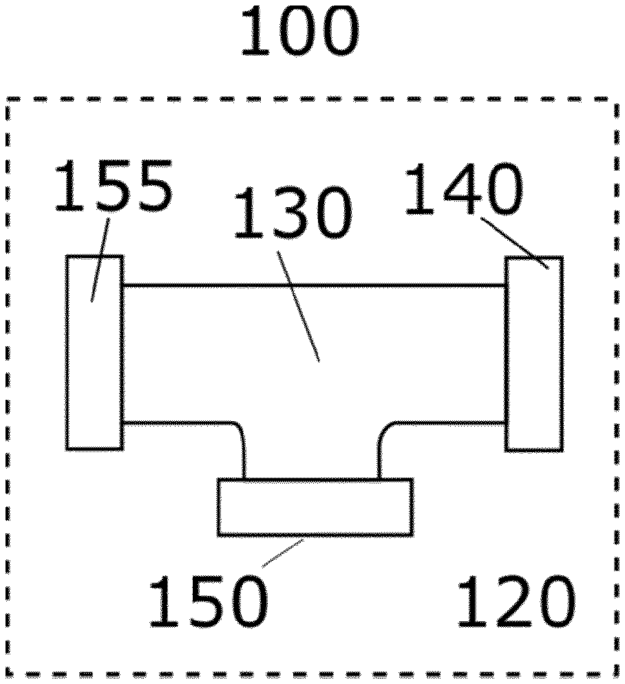
[0005] External branched connection assemblies are, however, usually large in size and thus requires additional space on the seabed adjacent to or in the vicinity of the production manifold. Their installation is also cumbersome, as it may require the disassembling, and cut back, of a jumper before the external branched connection assembly can be connected to the production manifold.
[0006] It is the goal of the present invention to provide an improved solution for how to connect multiple jumpers to a single production manifold tie-in hub.
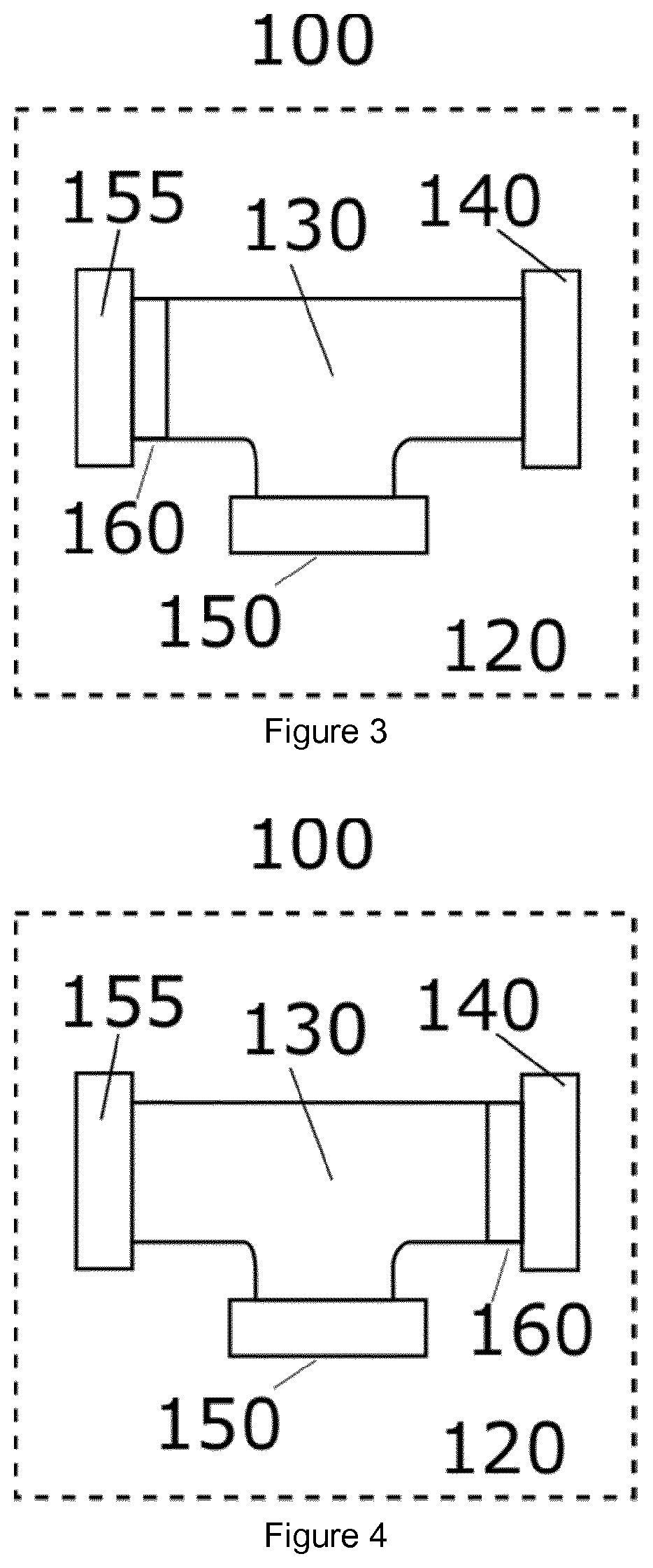
SUMMARY OF THE INVENTION
[0007] In a first aspect of the present invention, the invention provides a subsea assembly comprising a well multiplier assembly, where the well multiplier assembly comprises a branched pipe, a tie-in hub coupling, at least one tie-in hub, and a well multiplier assembly connection, where the branched pipe extends between the tie-in hub coupling, the at least one tie-in hub (150) and the well multiplier assembly connection.
[0008] According to one embodiment of the present invention each tie-in hub may associated with a closing valve arrangement. The well multiplier assembly connection may be associated with a closing valve arrangement. The tie-in hub coupling may be fitted with a closing valve arrangement.
[0009] According to another embodiment of the invention the well multiplier assembly connection is a tie-in hub.
[0010] According to yet another embodiment of the invention the branched pipe may be a Y-branch or a tee branch. The branched pipe may be in one piece.
[0011] According to yet another embodiment of the invention the at least one tie-in hub may be arranged in a nonparallel direction relative to the tie-in hub coupling. The at least one tie-in hub may alternatively be arranged in a perpendicular direction relative to the tie-in hub coupling.
[0012] According to yet another embodiment of the invention the at least one tie-in hub is fitted with a tie-in hub connector.
[0013] According to yet another embodiment of the invention, the well multiplier assembly further comprises a flowline integrally attached to the well multiplier assembly connection. The flowline may be integrally attached to the well multiplier assembly connection using welding or flange coupling. The well multiplier assembly connection may be integrally attached to the branched pipe.
[0014] According to yet another embodiment of the invention the subsea assembly may further comprise a termination assembly, where the termination assembly comprises one or more of the elements chosen from the group comprising a barrel in barrel alignment means, a guide funnel, a insertion interface and landing bracket means.
[0015] In a second aspect of the present invention, the invention provides a jumper connection method comprising the steps of providing a subsea assembly comprising a well multiplier assembly, where the well multiplier assembly comprises a branched pipe, a tie-in hub coupling, at least one tie-in hub and a well multiplier assembly connection, where the branched pipe extends between the tie-in hub coupling, the at least one tie-in hub and the well multiplier assembly connection, providing a subsea production unit tie-in hub, providing a first jumper, providing a second jumper, connecting the tie-in coupling to the subsea production unit tie-in hub, connecting the first jumper to the well multiplier assembly connection of the well multiplier assembly, and connecting the second jumper to a tie-in hub of the well multiplier assembly.
[0016] According to another embodiment of the invention, the step of providing a subsea production unit tie-in hub involves providing a subsea production unit comprising a tie-in hub.
[0017] According to another embodiment of the subsea production unit is a production manifold or a Christmas tree.
[0018] According to yet another embodiment of the invention the method further comprises the steps of providing each tie-in hub of the well multiplier assembly with a closing valve arrangement, and opening the closing valve arrangement of the tie-in hub to which the second jumper is connected.
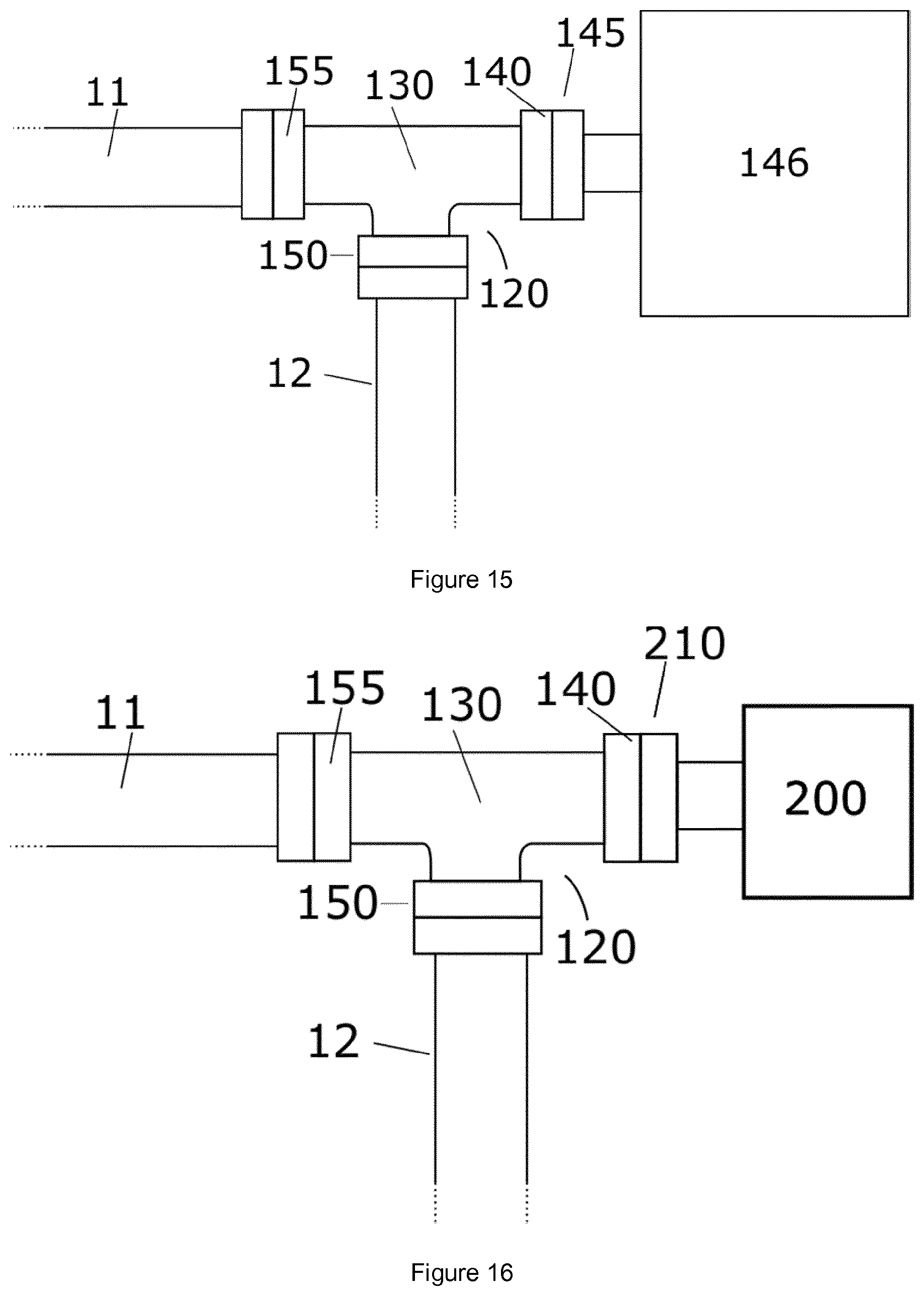
[0019] According to yet another embodiment of the invention the method further comprises the steps of providing the well multiplier assembly connection with a closing valve arrangement, and opening the closing valve arrangement of the well multiplier assembly connection.
[0020] According to yet another embodiment of the invention the method further comprises the steps of providing any one of the tie-in hub coupling, the tie-in hub, the well multiplier assembly connection or the subsea production unit tie-in hub with an end cap or cover means, and opening or removing the respective end cap or cover means when the tie-in hub coupling, the tie-in hub, the well multiplier assembly connection or the subsea production unit tie-in hub provided with an end cap or cover means is connected to the subsea production unit, the second jumper, the first jumper or the subsea assembly respectively.
[0021] According to yet another embodiment of the invention the step of connecting the first jumper to the well multiplier assembly connection may involve integrally connecting the first jumper to the well multiplier assembly connection.
[0022] In a third aspect of the present invention, the invention provides a subsea production system comprising a subsea assembly comprising a well multiplier assembly, where the well multiplier assembly comprises a branched pipe, a tie-in hub coupling, at least one tie-in hub and a well multiplier assembly connection, where the branched pipe extends between the tie-in hub coupling, the at least one tie-in hub and the well multiplier assembly connection, a first jumper, and a second jumper, where the first jumper is connected to the well multiplier assembly connection and where the second jumper is connected to a tie-in hub.
[0023] According to an embodiment of the invention the subsea production system further comprises a production manifold, where the production manifold comprises a production manifold tie-in hub, and where the tie-in hub coupling of the well multiplier assembly is connected to the production manifold tie-in hub.
[0024] According to another embodiment of the invention the subsea production system further comprises a Christmas tree, where the Christmas tree comprises a Christmas tree tie-in hub, and where the tie-in hub coupling of the well multiplier assembly is connected to the Christmas tree tie-in hub.
[0025] According to yet another embodiment of the invention the subsea production system further comprises a first Christmas tree and a second Christmas tree, where the first Christmas tree is connected to the subsea assembly using the first jumper and the second Christmas tree is connected to the subsea assembly using the second jumper.
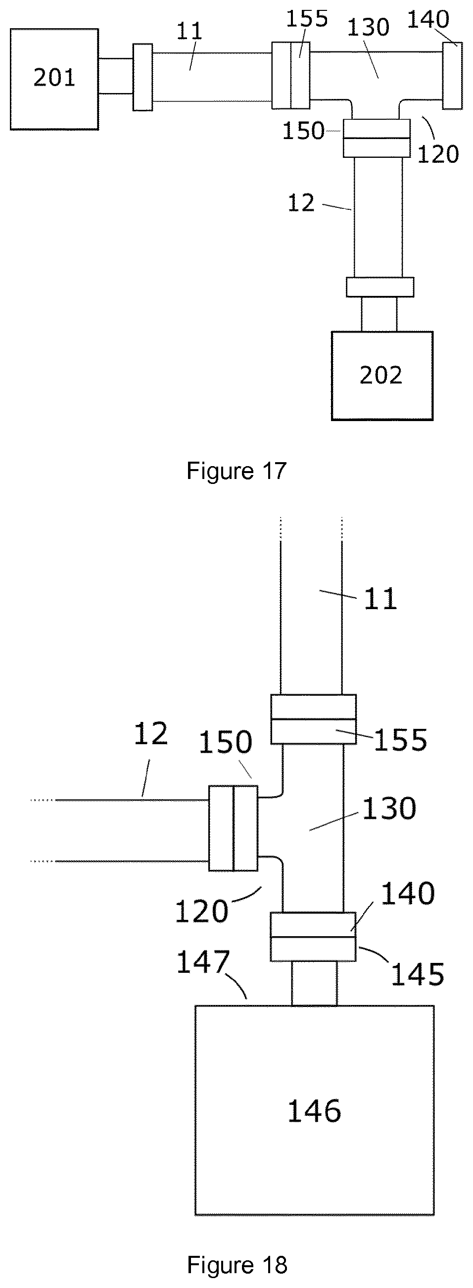
[0026] According to yet another embodiment of the invention the production manifold is provided with at least one production manifold tie-in hub on its top side.
[0027] Other advantageous features will be apparent from the accompanying claims.
BRIEF DESCRIPTION OF THE DRAWINGS
[0028] In order to make the invention more readily understandable, the discussion that follows will refer to the accompanying drawings, in which:
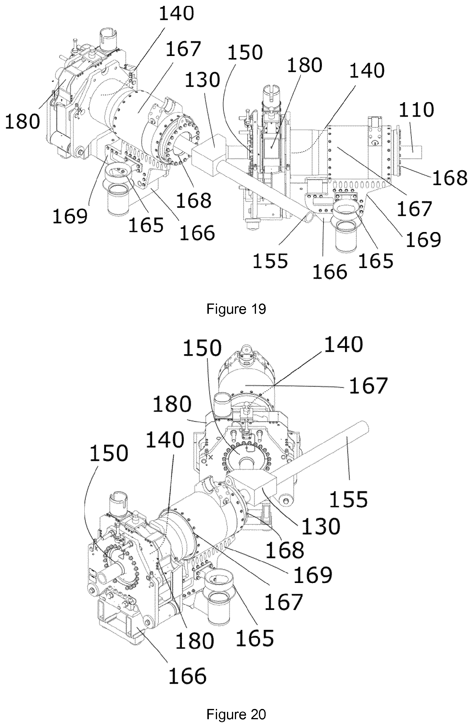
[0029] FIG. 1 is a schematic representation of a subsea assembly according to one embodiment of the invention;
[0030] FIG. 2 is a schematic representation of a subsea assembly where a tie-in hub is associated with a closing valve arrangement;
[0031] FIG. 3 is a schematic representation of a subsea assembly where a well multiplier assembly connection is associated with a closing valve arrangement;
[0032] FIG. 4 is a schematic representation of a subsea assembly where a tie-in hub coupling is associated with a closing valve arrangement;
[0033] FIG. 5 is a schematic representation of a subsea assembly where a well multiplier assembly connection is a tie-in hub;
[0034] FIG. 6 is a schematic representation of a subsea assembly where a branched pipe is a Y-branch;
[0035] FIG. 7 is a schematic representation of a subsea assembly where a branched pipe is a T-branch;
[0036] FIG. 8 is a schematic representation of a subsea assembly where a tie-in hub is fitted with a tie-in hub connector;
[0037] FIG. 9 is a schematic representation of a subsea assembly comprising a jumper/flowline integrally attached to a well multiplier assembly connection;
[0038] FIG. 10 is a schematic representation of a subsea assembly comprising a jumper/flowline integrally attached to a well multiplier assembly connection using welding or flange coupling;
[0039] FIG. 11 is a schematic representation of a jumper connection method where a subsea assembly is connecting with a first jumper and a second jumper;
[0040] FIG. 12 is a schematic representation of a jumper connection method where a subsea assembly is connecting with a production manifold;
[0041] FIG. 13 is a schematic representation of a jumper connection method where a subsea assembly is connecting with a Christmas tree;
[0042] FIG. 14 is a schematic representation of a subsea production system where a subsea assembly is connected to a first jumper and a second jumper;
[0043] FIG. 15 is a schematic representation of a subsea production system where a production manifold is connected to a subsea assembly;
[0044] FIG. 16 is a schematic representation of a subsea production system where a Christmas tree is connected to a subsea assembly;
[0045] FIG. 17 is a schematic representation of a subsea production system where a subsea assembly is connected to a first Christmas tree and a second Christmas tree;
[0046] FIG. 18 is a schematic representation of a subsea production system where a production manifold is provided with a production manifold tie-in hub on its top side;
[0047] FIG. 19 is a schematic representation of a subsea assembly according to one embodiment of the invention;
[0048] FIG. 20 is a schematic representation of a subsea assembly according to one embodiment of the invention;
[0049] FIG. 21 is a schematic representation of a subsea assembly comprising a jumper/flowline integrally attached to a well multiplier assembly connection;
[0050] FIG. 22 is a schematic representation of a subsea production system according to one embodiment of the invention;
[0051] FIG. 23 is a schematic representation of a subsea production system according to one embodiment of the invention; and
[0052] FIG. 24 is a schematic representation of a subsea production system according to one embodiment of the invention.
DETAILED DESCRIPTION OF THE INVENTION
[0053] In the following, general embodiments as well as particular exemplary embodiments of the invention will be described. References will be made to the accompanying drawings. It shall be noted, however, that the drawings are exemplary embodiments only, and that other features and embodiments may well be within the scope of the invention as claimed.
[0054] The present invention relates to a device, method and system that enables connection of multiple jumpers onto a single tie-in hub.
[0055] The present invention involves a branched connection that enables two or more jumpers to be connected onto a single tie-in hub, e.g. that of a production manifold or a Christmas tree. The invention thus provides a solution that makes obsolete the installation of separated installations such as large external branched connection assemblies or additional separate production manifolds. The present invention offers several benefits over prior art, e.g. external branched connection assemblies, by i.a. offering a more compact design, lower requirements for seabed conditions, and lower cost of installation. A lower cost of installation can be achieved as the present invention may remove the need for a disconnection/stroke-back and/or jumper retrieval and modification.
[0056] A first aspect of the present invention is illustrated in FIG. 1. Here the invention provides a subsea assembly 100 comprising a well multiplier assembly 120, where the well multiplier assembly 120 comprises a branched pipe 130, a tie-in hub coupling 140, at least one tie-in hub 150, and a well multiplier assembly connection 155. The branched pipe 130 extends between the tie-in hub coupling 140, the at least one tie-in hub 150 and the well multiplier assembly connection 155. The at least one tie-in hub 150 and well multiplier assembly connection 155 allows for tie-in of multiple jumpers onto the subsea assembly 100, rendering possible the connection of multiple jumpers onto a single tie-in hub 145.
[0057] A well multiplier assembly connection may according to the present invention be considered as a general connection onto a well multiplier assembly. It may be configured to act as a connection for various subsea components, such as jumpers, umbilicals, pipelines, flow lines, power lines, and/or any other subsea module, and may comprise various fastening or securing means. According to one embodiment of the invention, a well multiplier assembly connection may be a tie-in hub.
[0058] FIGS. 2, 3 and 4 show respectively a tie-in hub 150, a well multiplier assembly connection 155 and a tie in hub coupling 140 that is associated with a closing valve arrangement 160. Each closing valve arrangement 160 may be configured to seal of its associated tie-in hub 150, well multiplier assembly connection 155 or tie in hub coupling 140, e.g. when the well multiplier assembly connection 155 is not connected to a jumper. A closing valve arrangement 160 may in general be fitted on or in any tie-in hub 150, well multiplier assembly connection 155 or tie in hub coupling 140, but could alternatively or additionally be fitted on or in the branched pipe 130 in order to close of an inlet/outlet of the branched pipe 130. A closing valve arrangement 160 can also be used in order to control the flow of fluid through a well multiplier assembly 120 based on e.g. various production, maintenance or plugging and abandonment schemes.
[0059] A tie-in hub coupling 140 of a well multiplier assembly 120 is illustrated in FIG. 4, where the tie-in hub coupling 140 it is fitted with a closing valve arrangement 160. The closing valve arrangement 160 may e.g. be used to keep the tie-in hub coupling 140 sealed, e.g. prior to installation, or alternatively used to control or direct ingoing/outgoing flow to/from a subsea assembly 100.
[0060] A subsea assembly may in general be fitted with any combination of valves that may be positioned e.g. at any outlet/inlet of a branched pipe of the well multiplier assembly. Such valves may be mechanically, hydraulically and/or electrically actuated and could e.g. be used to control fluid flow through the branched pipe, or alternatively operate as safety valves. Any tie-in hub, well multiplier assembly connection or tie-in hub coupling may for example be fitted with a pressure cap.
[0061] A tie-in hub coupling 140 is as illustrated in FIG. 11 configured to be at least be connectable with any tie-in hub 145, e.g. in order to connect two subsea elements to each other. Such subsea elements involve e.g. a jumper, well multiplier assembly 120, production manifold, subsea assembly 100, Christmas tree etc. Connection of two subsea elements to each other is typically performed in order to enable fluid connection between the two, enable electrical or hydraulic power to be transferred, etc.
[0062] A branched pipe 130 of a well multiplier assembly 120 may as illustrated in the accompanying figures be configured so that it extends between a well multiplier assembly 120 connection, a tie-in hub coupling 140 and a at least one tie-in hub 150 of the well multiplier assembly 120. The branched pipe 130 facilitates the bringing of the constituents of a subsea assembly 100 connection into fluid connection, allowing e.g. for fluid flowing into the well multiplier assembly 120 through the well multiplier assembly connection 155 to be directed by the branched pipe 130 to the tie-in hub coupling 140 and the at least one tie-in hub 150. The branched pipe 130 of the well multiplier assembly 120 is illustrated in e.g. FIG. 1 a chamber having three or more inlets/outlets through which a fluid can flow. The branched pipe 130 is in this case configured to distribute a fluid from one or more inlets to one or more outlets.
[0063] FIG. 1 illustrates a branched pipe 130 shaped as a one-to-two branched pipe extending between a well multiplier assembly connection 155, a tie-in hub 150 and a tie-in hub coupling 140 of the well multiplier assembly 120. The branched pipe 130 could for example be a Y-branch 131 or a tee branch 132, as can be seen in FIGS. 6 and 7 respectively. The branched pipe 130 may be made up by a plurality of separate parts fitted together, but is preferably made out of one single integral piece of material using a technique like milling, cutting, moulding, casting or similar. The branched pipe 130 may be made out of one or more materials chosen from the group comprising polymers, metals, composite materials, ceramics, or any combination of the aforementioned, and could optionally be coated on either side, e.g. by an anti-corrosion coating.
[0064] FIGS. 5 and 7 respectively illustrates a well multiplier assembly 120 where either or both of at least one tie-in hub 150 and a well multiplier assembly connection 155 is arranged in a nonparallel direction relative to a tie-in hub coupling 140. This arrangement allows for branched connection of multiple jumpers onto e.g. a single production manifold tie-in hub, where the jumpers don't have to point in the same direction. An arrangement of at least one tie-in hub 150 in a non-parallel direction relative to the tie-in hub coupling 140 allows i.a. for optimization of the space in all spatial directions surrounding any tie-in hub to which the subsea assembly 100 may connect.
[0065] FIG. 7 illustrates a well multiplier assembly 120 where at least one tie-in hub 150 is arranged in a perpendicular direction relative to a tie-in hub coupling 140 of a well multiplier assembly 120. The direction of the tie-in hub coupling 140 is generally considered to be the same direction as the intended direction of flow of a production fluid through the tie-in hub coupling 140. The perpendicular arrangement of a tie-in hub 150 of the well multiplier assembly 120 enables branched connection of jumpers to be made in the vertical direction relative to e.g. a production manifold tie-in hub arranged in the horizontal direction. A branched connection of jumpers may alternatively be made in the horizontal direction relative to a production manifold tie-in hub arranged in the vertical direction. The present invention thus enables branched connections onto a production manifold tie-in hub 145 being arranged in a vertical direction on top of a production manifold. Existing solutions involving submerging separated units, e.g. skid-based units, will not be able to connect to such a tie-in hub without employing additional connectors extending from the separate unit to the production manifold tie-in hub.
[0066] FIG. 8 illustrates a well multiplier assembly 120 comprising a tie-in hub 150 fitted with a tie-in hub connector 180. The tie-in hub connector 180 is configured to connect a tie-in hub coupling 140 to a tie-in hub 150, e.g. by clamping or locking the tie-in hub 150 and the tie-in hub coupling 140 together. The tie-in hub connector 180 is mechanically, hydraulically and/or electrically actuated. The tie-in hub 140 or tie-in hub connector 180 may be provided with a seal or end cap arranged or formed between the tie-in hub 150 and tie-in hub coupling 140, e.g. against the surrounding seawater. The seal or end cap is opened in connection with the tie-in hub 150 being connected to a jumper or pipe section.
[0067] FIG. 9 illustrates a subsea assembly 100 comprising a flowline 110/jumper 110 that is integrally attached to a well multiplier assembly 120. The flowline 110/jumper 110 may as illustrated in FIG. 10 be integrally attached to a well multiplier assembly connection 155 of the well multiplier assembly 120, by e.g. using a weld 171, a permanent flange coupling 172, clamp, etc. The flowline 110/jumper 110 may alternatively be unitarily attached to the well multiplier assembly connection 155, or alternatively be integrally or unitarily attached directly to the branched pipe 130.
[0068] FIG. 11 illustrates a method for connecting at least a first jumper 11 and a second jumper 12 to a subsea assembly 100. The subsea assembly 100 comprises a well multiplier assembly 120, where the well multiplier assembly 120 comprises a branched pipe 130, a tie-in hub coupling 140, at least one tie-in hub 150 and a well multiplier assembly connection 155. The branched pipe 130 extends between the tie-in hub coupling 140, the at least one tie-in hub 150 and the well multiplier assembly connection 155.
[0069] A jumper connection method is visualized in FIG. 11, where it comprises the steps of providing a first jumper 11, providing a second jumper 12, providing a subsea assembly 100, connecting the first jumper 11 to the well multiplier assembly connection 155 of the well multiplier assembly 120 and connecting the second jumper 12 to a tie-in hub 150 of the well multiplier assembly 120, e.g. by means of a tie-in hub connector. A jumper may according to any embodiment of the present invention comprise a tie-in hub coupling 140 on one end. The tie-in hub 150 may be provided with a tie-in hub connector, which may connect the tie-in hub 150 and the jumper 12 or any other pipeline.
[0070] A well multiplier assembly connection can be considered as comprising means that allow the connection of a jumper or flowline. The well multiplier assembly connection may e.g. be a tie-in hub, but could be any type of connection that allows for the connection of a jumper or other flowline. The connecting of a jumper to a subsea assembly may thus comprise connecting a tie-in hub coupling of the jumper to a tie-in hub of a well multiplier assembly of the subsea assembly. The connecting of a jumper to the subsea assembly may alternatively comprise connecting a tie-in hub coupling of the jumper to a tie-in hub of the well multiplier assembly of the subsea assembly. The connecting of a jumper to the subsea assembly may alternatively comprise connecting a tie-in hub coupling on a tie-in hub to a jumper. The well multiplier assembly may alternatively comprise a tie-in hub coupling being connected to a jumper or other flowline.
[0071] FIG. 12 illustrates a jumper connection method comprising a connection of a subsea assembly to a subsea production unit, such as a production manifold. Here, the method comprises the steps of providing a production manifold 146, and connecting the subsea assembly 100 to the production manifold 146. The production manifold 146 is in this embodiment fitted with a tie-in hub, i.e. a production manifold tie-in hub 145, and the step of connecting the subsea assembly 100 to the production manifold 146 may thus comprise connecting the tie-in hub coupling 140 of the well multiplier assembly 120 of the subsea assembly to the production manifold tie-in hub 145.
[0072] As an alternative to connecting a subsea assembly 100 to a production manifold 146, the subsea assembly 100 may as illustrated in FIG. 13 be connected to other subsea production units, such as a Christmas tree 200.
[0073] This will create a branched connection for jumpers on the Christmas tree 200. A jumper connection method may in this case comprise the steps of providing a Christmas tree 200, and connecting the subsea assembly 100 to the Christmas tree 200. The Christmas tree 200 may comprise a tie-in hub 150, i.e. a Christmas tree tie-in hub 210, and the step of connecting the subsea assembly to the Christmas tree 200 may comprise connecting the tie-in hub coupling 140 of the well multiplier assembly 120 to the Christmas tree tie-in hub 210.
[0074] A jumper connection method may further comprise the step of providing any tie-in hub, well multiplier assembly connection or tie-in hub coupling of a well multiplier assembly with a closing valve arrangement. A closing valve arrangement can be opened and closed on demand, and a closing valve arrangement provided on a tie-in hub of the well multiplier assembly may thus e.g. be opened after a jumper is connected to that tie-in hub. A closing valve arrangement associated with a well multiplier assembly connection can similarly e.g. be opened after a jumper is connected to the well multiplier assembly connection.
[0075] A step of connecting a first jumper to a well multiplier assembly connection may involve integrally connecting the first jumper to the well multiplier assembly connection. The step of connecting the first jumper to the well multiplier assembly connection may be performed prior to submerging and installing the subsea assembly and may thus be performed using methods like welding, clamping or permanent flange coupling. The first jumper may e.g. by integrally connected onto the branched pipe so as to form one piece with the branched pipe.
[0076] FIG. 14 illustrates a subsea production system 101 comprising a subsea assembly 100, a first jumper 11, and a second jumper 12. The subsea assembly 100 comprises a well multiplier assembly 120. The first jumper 11 is here connected to a well multiplier assembly connection 155 of a well multiplier assembly 120 and the second jumper 12 is connected to a tie-in hub 150 of the well multiplier assembly 120. Any one of the jumpers may be substituted with another subsea assembly allowing for further branched connection of jumpers. FIG. 22-24 illustrates a production system where two subsea assemblies are connected to a production manifold.
[0077] FIG. 15 illustrates a subsea production system 101 comprising a production manifold 146 to which a subsea assembly 100 may be connected. The production manifold 146 comprises according to this embodiment of the invention a tie-in hub 150, i.e. a production manifold tie-in hub 145, to which the tie-in hub coupling 140 of the well multiplier assembly 120 is connected. FIG. 16 illustrates a subsea production system comprising a Christmas tree 200, where a well multiplier assembly 120 of a subsea assembly 110 is connected to the Christmas tree 200. The Christmas tree 200 may comprise a tie-in hub, i.e. a Christmas tree tie-in hub 210, to which a tie-in hub coupling 140 of the well multiplier assembly 120 is connected.
[0078] FIG. 17 illustrates a subsea production system comprising a first Christmas tree 201 and a second Christmas tree 202. The first Christmas tree 201 may be connected to a subsea assembly 100 using the first jumper 11 and the second Christmas tree 202 may be connected to the same subsea assembly 100 using the second jumper 12. An example of a production system comprising a first Christmas tree 201 and a second Christmas tree 202 is illustrated in FIG. 17.
[0079] A production manifold 146 may as illustrated in FIG. 18 be provided with at least one production manifold tie-in hub 145 on at least one of its sides, or alternatively be provided with one or more production manifold tie-in hubs 145 either on opposing sides or the top side 147.
[0080] A production manifold tie-in hub 145 being provided on a production manifold top side 147 is incompatible with many existing external branched connection assemblies that are dependent on being positioned adjacent to the production manifold tie-in hub. The subsea assembly 100 according to the present invention may be mounted on vertically aligned production manifold tie-in hubs 145.
[0081] Any of the tie-in hub coupling, the tie-in hub and the well multiplier assembly connection of the subsea assembly may be covered by an end cap or other cover means prior to being connected to a subsea production unit, jumper/flowline. The end cap or other cover means is removed or opened when the subsea assembly is connected to a jumper/flowline or subsea production unit. Any tie-in hub, jumper/flowline may also be provided with an end cap or cover means which may be opened or removed when the subsea assembly is connected to the subsea production unit tie-in hub or jumper/flowline.
[0082] FIG. 19 illustrates a subsea assembly according to an embodiment of the invention, where the subsea assembly is fitted with a termination assembly and where the tie in hub of the subsea assembly is connected to a jumper 110 by employing a tie-in hub connector 180. Any jumper or subsea assembly may according to any embodiment of the invention be fitted with, or be integrally attached to, a termination assembly. A termination assembly may be associated with or positioned adjacent to any tie-in hub coupling. A termination assembly may be fitted with, or comprise, any combination or assortment amongst barrel in barrel alignment means 167, a guide funnel 165, an insertion interface 168 and landing bracket means 169. Any tie-in hub 150 or tie-in hub connector 180 may be fitted with, or comprise, any combination or assortment amongst a guide funnel, and a landing beam 166.
[0083] A termination assembly can e.g. be used in order to aid the tie-in of a jumper 110 or subsea assembly onto a tie-in hub 150. Landing bracket means 169 may according to the invention be configured to couple with a landing beam 166. Any guidepost may according to the invention be configured to fit inside a guide funnel 165.
[0084] FIG. 20 illustrates the same subsea arrangement as FIG. 19 viewed from a different angle. The subsea assembly can here be seen to be connected with one tie-in hub 150, which may be part of an associated production manifold, Christmas tree or other structure.
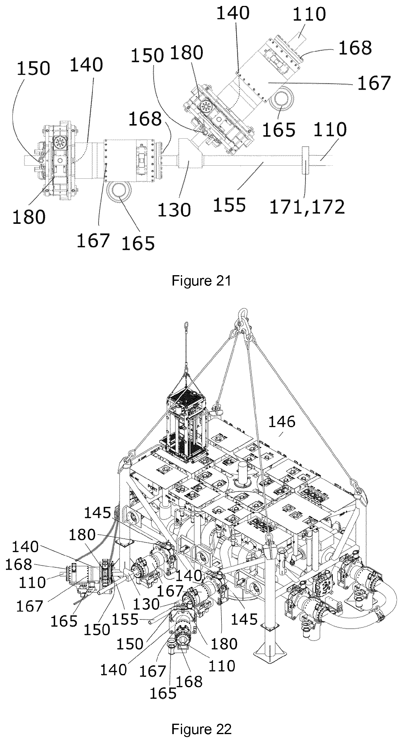
[0085] FIG. 21 illustrates a subsea assembly like the one illustrated in FIG. 19, further comprising a flowline/jumper 110 that is integrally attached to the well multiplier assembly of the subsea assembly. The flowline/jumper 110 may as illustrated be integrally attached to a well multiplier assembly connection 155 of the well multiplier assembly, by e.g. using a weld 171, a permanent flange coupling 172, clamp, etc. The flowline/jumper 110 may alternatively be unitarily attached to the well multiplier assembly connection 155, or alternatively be integrally or unitarily attached directly to the branched pipe 130.
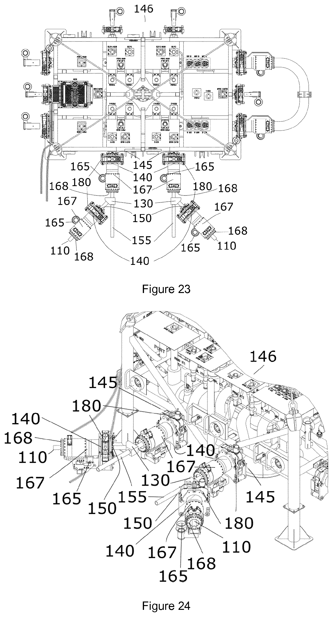
[0086] FIG. 22 illustrates a subsea system comprising two subsea assemblies like the one illustrated by FIGS. 19 and 20 that are connected to a production manifold 146. Each subsea assembly is here tied in on a production manifold tie-in hub 145. The connection of a subsea assembly onto a production manifold tie-in hub enables the connection of two jumpers, onto one production manifold tie-in hub. FIG. 23 illustrates a top view of the subsea system illustrated in FIG. 22. FIG. 24 illustrates a zoomed in view of the subsea system illustrated in FIG. 22.
[0087] Other advantageous features will be apparent from the accompanying claims.
TABLE-US-00001 11 First jumper 12 Second jumper 100 Subsea assembly 101 Subsea production system 110 Flowline/jumper 120 Well multiplier assembly 130 Branched pipe 131 Y-branch 132 T-branch 140 Tie-in hub coupling 145 Production manifold tie-in hub 146 Production manifold 147 Production manifold top side 150 Tie-in hub 155 Well multiplier assembly connection 160 Closing valve arrangement 165 Guide funnel 166 Landing beam 167 Barrel in barrel alignment means 168 Insertion interface 169 Landing bracket means 170 Integral attachment point 171 Weld 172 Flange coupling 180 Tie-in hub connector 190 Pressure cap 200 Christmas tree 201 First Christmas tree 202 Second Christmas tree 210 Christmas tree tie-in hub
TABLE-US-00002 Terminology Definition Tie-in hub Connection/tie-in point configured to be connectable with any tie-in hub coupling. A tie-in hub may i.a. be provided on production manifolds and subsea assemblies. Production manifold Tie-in hub provided on a production tie-in hub manifold configured to be connectable with any tie-in hub coupling. Tie-in hub coupling Coupling configured to be connectable with any tie-in hub. A tie-in hub coupling is according to the present invention i.a. provided on subsea assemblies and jumpers. Tie-in hub connector A connector configured to connect a tie- in hub coupling to a tie-in hub by clamping or locking the two together.
* * * * *
D00000
D00001
D00002
D00003
D00004
D00005
D00006
D00007
D00008
D00009
D00010
D00011
D00012
XML
uspto.report is an independent third-party trademark research tool that is not affiliated, endorsed, or sponsored by the United States Patent and Trademark Office (USPTO) or any other governmental organization. The information provided by uspto.report is based on publicly available data at the time of writing and is intended for informational purposes only.
While we strive to provide accurate and up-to-date information, we do not guarantee the accuracy, completeness, reliability, or suitability of the information displayed on this site. The use of this site is at your own risk. Any reliance you place on such information is therefore strictly at your own risk.
All official trademark data, including owner information, should be verified by visiting the official USPTO website at www.uspto.gov. This site is not intended to replace professional legal advice and should not be used as a substitute for consulting with a legal professional who is knowledgeable about trademark law.