Flat Pack Convertible Four Sided Storage Box and Eight Sided Nesting Tote Box
Traub; Eliezer
U.S. patent application number 16/862853 was filed with the patent office on 2020-11-05 for flat pack convertible four sided storage box and eight sided nesting tote box. The applicant listed for this patent is Eliezer Traub. Invention is credited to Eliezer Traub.
| Application Number | 20200346817 16/862853 |
| Document ID | / |
| Family ID | 1000004827527 |
| Filed Date | 2020-11-05 |


| United States Patent Application | 20200346817 |
| Kind Code | A1 |
| Traub; Eliezer | November 5, 2020 |
Flat Pack Convertible Four Sided Storage Box and Eight Sided Nesting Tote Box
Abstract
A flat pack convertible stackable four sided storage box and eight sided nesting tote box comprises a base, two opposed longitudinal sides, two end sides having at least one cutline defining at least one end side opening, four triangular expansion sides with each triangular expansion side located adjacent one of the sides, and four moving conversion panels with each panel adjacent one of the expansion sides, each panel includes at least one panel opening configured to selectively align with one opening formed by at least one cutline and configured to receive a locking element there-through to be locked into one position, wherein in one position a stackable four sided storage box is formed and in another position an eight sided nesting tote box is formed and the box may be moved back and forth between the two configurations.
| Inventors: | Traub; Eliezer; (Ramat-Gan, IL) | ||||||||||
| Applicant: |
|
||||||||||
|---|---|---|---|---|---|---|---|---|---|---|---|
| Family ID: | 1000004827527 | ||||||||||
| Appl. No.: | 16/862853 | ||||||||||
| Filed: | April 30, 2020 |
Related U.S. Patent Documents
| Application Number | Filing Date | Patent Number | ||
|---|---|---|---|---|
| 62920465 | May 2, 2019 | |||
| Current U.S. Class: | 1/1 |
| Current CPC Class: | B65D 5/4608 20130101; B65D 21/0233 20130101; B65D 5/64 20130101; B65D 5/241 20130101; B65D 5/0015 20130101; B65D 5/0005 20130101 |
| International Class: | B65D 5/00 20060101 B65D005/00; B65D 21/02 20060101 B65D021/02; B65D 5/64 20060101 B65D005/64; B65D 5/24 20060101 B65D005/24; B65D 5/355 20060101 B65D005/355; B65D 5/468 20060101 B65D005/468 |
Claims
1. A flat pack convertible stackable four sided storage box and eight sided nesting tote box comprising: A base [110, 310] including two parallel base longitudinal score lines [112, 312] and two parallel base end score lines [114, 314]; two opposed longitudinal sides [120, 320] each longitudinal side [120, 320] adjacent one of the base longitudinal score lines [112, 312] and having opposed longitudinal side end score lines [122, 322]; two end sides [130, 330], each end side [130, 330] adjacent one of the base end score lines [114, 314] and having at least one cutline [136, 336] defining at least one end side opening; four triangular expansion sides [140, 340] each triangular expansion side [140, 340] located adjacent one of the side end score lines [122, 322] and having an expansion side score line [142, 342]; four moving conversion panels [150, 350] each panel [150, 350] adjacent one of the expansion side score line [142, 342], each panel [150, 350] includes at least one panel opening [152, 352] configured to selectively align with one opening formed by at least one cutline [136, 336] and configured to receive a locking element [138, 370] there-through to be locked into one position, wherein in one position a stackable four sided storage box [100, 300] is formed as one configuration and in another position an eight sided nesting tote box [100, 300] is formed as a second configuration and wherein the box [100, 300] may be moved back and forth between the two configurations.
2. The convertible box of claim 1, wherein the base [110] includes two openings along each base end score line [114] configured for receiving elements [166] which help secure the box [100] in both the stackable four sided storage box [100] configuration and the eight sided nesting tote box [100] configuration.
3. The convertible box of claim 2, further including a pair of inner end sides [160], each inner end side [160] adjacent one end side [130].
4. The convertible box of claim 3, wherein each inner end side [160] includes a score line [162] offset from a score line [134] at the top of the end side [130] by a thickness adapted to accommodate folding the inner end sides [160] such that the inner end side [160] and the end side [130] are on opposite sides of intervening conversion panels [150].
5. The convertible box of claim 4, wherein each inner end side [160] includes an opening [164] that aligns with the at least one end side opening.
6. The convertible box of claim 5, wherein the at least one end side opening in each end side [130] forms an oval handle opening for the box [100].
7. The convertible box of claim 6, wherein each cutline [136] in each end side defines a locking tab [138] forming the locking element.
8. The convertible box of claim 7, wherein each panel includes a second panel opening [156] configured to selectively align with one opening formed by at least one cutline [136] and configured to receive the locking tab [138] there-through to be locked into a second position.
9. The convertible box of claim 1, wherein the box is formed of cardboard, plastic, corrugated plastic cardboard.
10. The convertible box of claim 1, wherein the box [100, 300] includes a lid [200] configured to be secured on top of the box [100, 300] when in the storage box configuration.
11. The convertible box of claim 10, wherein the lid [200] is formed of cardboard, plastic, corrugated plastic cardboard.
12. The convertible box of claim 10, wherein the lid [200] is configured to convert to an eight sided nesting tote box.
13. The convertible box of claim 1, wherein each locking element is a one piece double headed connecting stud [370].
14. The convertible box of claim 13, wherein each stud [370] is received within an oval opening formed by at least one cutline in an end side and is configured to be moved between one position locking the box in a configuration and a second position allowing the box to be converted from one configuration to the second configuration.
15. The convertible box of claim 14, wherein each panel opening [352] is formed as a slot with two detent positions.
16. A flat pack convertible stackable four sided storage box and eight sided nesting tote box comprising: A rectangular base [110, 310]; two opposed longitudinal sides [120, 320]; two end sides [130, 330], each end side [130, 330] having at least one cutline [136, 336] defining at least one end side opening; four triangular expansion sides [140, 340]; four moving conversion panels [150, 350], each panel [150, 350] including at least one panel opening [152, 352] configured to selectively align with one opening formed by at least one cutline [136, 336] and configured to receive a locking element [138, 370] there-through to be locked into one position, wherein in one position a stackable four sided storage box [100, 300] is formed as one configuration and in another position an eight sided nesting tote box [100, 300] is formed as a second configuration and wherein the box [100, 300] may be moved back and forth between the two configurations; a lid [200] configured to be secured on top of the box [100, 300] when in the storage box configuration.
17. The convertible box of claim 16, wherein the lid [200] is configured to convert to an eight sided nesting tote box.
18. The convertible box of claim 16, wherein the box is formed of cardboard, plastic, corrugated plastic cardboard.
19. The convertible box of claim 16, wherein each locking element is a one piece double headed connecting stud [370].
20. The convertible box of claim 16, further including a pair of inner end sides [160], each inner end side [160] adjacent one end side [130].
Description
RELATED APPLICATIONS
[0001] The present application claims the benefit of U.S. Provisional Patent Application Ser. No. 62/920,465 filed May 2, 2019 titled "Opened Tray, or Opened Box, or Opened Container with Straight up Side Walls that can Flare Out and Retract Back" which is incorporated herein by reference.
BACKGROUND OF THE INVENTION
1. Field of the Invention
[0002] This invention generally relates to flat pack storage boxes, more specifically to flat pack storage boxes that are expandable to a larger size.
2. Background Information
[0003] The phrase "flat pack" within the meaning of the present application references products assembled from a one or more planar components that are assembled to the desired product. The phrase "flat pack" is often used in referencing furniture. In the field of the present invention, namely boxes and trays, this phrase "flat pack" can be equated with the phrase "knock down." See, for example, the "Corrugated Plastic Knockdown Tray" sold by Minnesota Diversified or the "Knock Down Storage Box" sold by Bigso Box of Sweden. The terms "Collapsible" and "Foldable", and similar terms, have also been used in this industry to convey the same concept and can also accurately describe the present invention.
[0004] The terms "boxes" and "trays" do not have consistent and precise definition in the art and can be interchangeably used together with the terms container, bin, receptacle, crate, chest, trunk, carton, and a host of other similar terms. Within the meaning of the present application the phrase "storage box" defines a container with substantially vertical sides (+/-7 degrees), and the phrase "nesting tote box" defines a container with non-vertical sides that extend upward at an angle of more than 7 degrees from vertical and less than 75 degrees from vertical, also called "flared sided" herein, wherein the containers may be nested together. The nesting of the tote boxes generally aids in storage and shipment of the containers. The flared sides of a nesting tote box yield numerous other advantages, such as ease of access to contained articles that are lower in a stack of article within the nesting tote box. The outward angle yield a greater containment volume within the box than if the sides extended vertically from the base, thus yielding greater containment volume. Further the nesting tote box design offers an improved display of products within the nesting tote box then a storage box would in some commercial establishments. For example, there are some supermarkets that minimize shelving labor and display products within shipping containers, and a nesting tote box allows for a better display of products on the shelf, although the storage box is preferable for product shipping.
[0005] The U.S. patent system has long illustrated the ingenuity of flat pack containers, such as the 1894 U.S. Pat. No. 529,053 for a "Paper Pail", which was later emblazoned with the graphical image of a pagoda, and has become well known as the now ubiquitous "Chinese food" take out container.
[0006] As noted above the present invention is directed to flat pack storage boxes that are expandable to a larger size. The U.S. patent system also shows innovations in this specific flat pack container field as well, with U.S. Pat. Nos. 2,793,802; 3,373,923; 3,520,409; and 4,111,306 being representative examples of these boxes. These patents are incorporated herein by reference.
[0007] There remains a need in the art to design cost effective, efficient and effective flat pack storage boxes that are expandable.
SUMMARY OF THE INVENTION
[0008] The various embodiments and examples of the present invention as presented herein are understood to be illustrative of the present invention and not restrictive thereof and are non-limiting with respect to the scope of the invention.
[0009] The present invention provides a flat pack convertible stackable four sided storage box and eight sided nesting tote box. Specifically one embodiment of the present invention provides a flat pack convertible stackable four sided storage box and eight sided nesting tote box which comprises a base including two parallel base longitudinal score lines and two parallel base end score lines, two opposed longitudinal sides each longitudinal side adjacent one of the longitudinal score lines and having opposed longitudinal side end score lines, two end sides with each end side adjacent one of the base end score lines and having at least one cutline defining at least one end side opening, four triangular expansion sides each triangular expansion side located adjacent one of the side end score lines and having an expansion side score line, four moving conversion panels with each panel adjacent one of the expansion side score line, each panel includes at least one panel opening configured to selectively align with one opening formed by at least one cutline and configured to receive a locking element there-through to be locked into one position, wherein in one position a stackable four sided storage box is formed and in another position an eight sided nesting tote box is formed and the box may be moved back and forth between the two configurations.
[0010] One embodiment of the present invention provides a flat pack convertible stackable four sided storage box and eight sided nesting tote box comprising: a rectangular base; two opposed longitudinal sides; two end sides, each end side having at least one cutline defining at least one end side opening; four triangular expansion sides; four moving conversion panels, each panel including at least one panel opening configured to selectively align with one opening formed by at least one cutline and configured to receive a locking element there-through to be locked into one position, wherein in one position a stackable four sided storage box is formed as one configuration and in another position an eight sided nesting tote box is formed as a second configuration and wherein the box may be moved back and forth between the two configurations; and a lid configured to be secured on top of the box when in the storage box configuration.
[0011] These and other advantages of the present invention will be clarified in the description of the preferred embodiments taken together with the attached figures.
BRIEF DESCRIPTION OF THE DRAWINGS
[0012] FIG. 1A is a perspective view of a flat pack stackable four sided storage box in accordance with a first embodiment of the present invention and shown without a lid and which storage box can convert to an eight sided nesting tote box;
[0013] FIG. 1B is a perspective view of the flat pack stackable four sided storage box of FIG. 1A converted to an eight sided nesting tote box;
[0014] FIG. 2A is a perspective view of a nested set of a plurality of eight sided nesting tote boxes of FIG. 1B with a nested set of a plurality of eight sided nesting tote box lids and an exploded perspective view of the nested boxes and nested lids;
[0015] FIG. 2B is a perspective view of a stacked set of a plurality of four sided storage boxes of FIG. 1A with storage box lids;
[0016] FIG. 3A is a top plan view of a flat die cut substrate used in forming the flat pack stackable four sided storage box of FIG. 1A and the eight sided nesting tote box of FIG. 1B;
[0017] FIG. 3B is a top plan view of a flat die cut substrate used in forming the lid for the flat pack stackable four sided storage box of FIG. 2B and the eight sided nesting tote box lids of FIG. 2A;
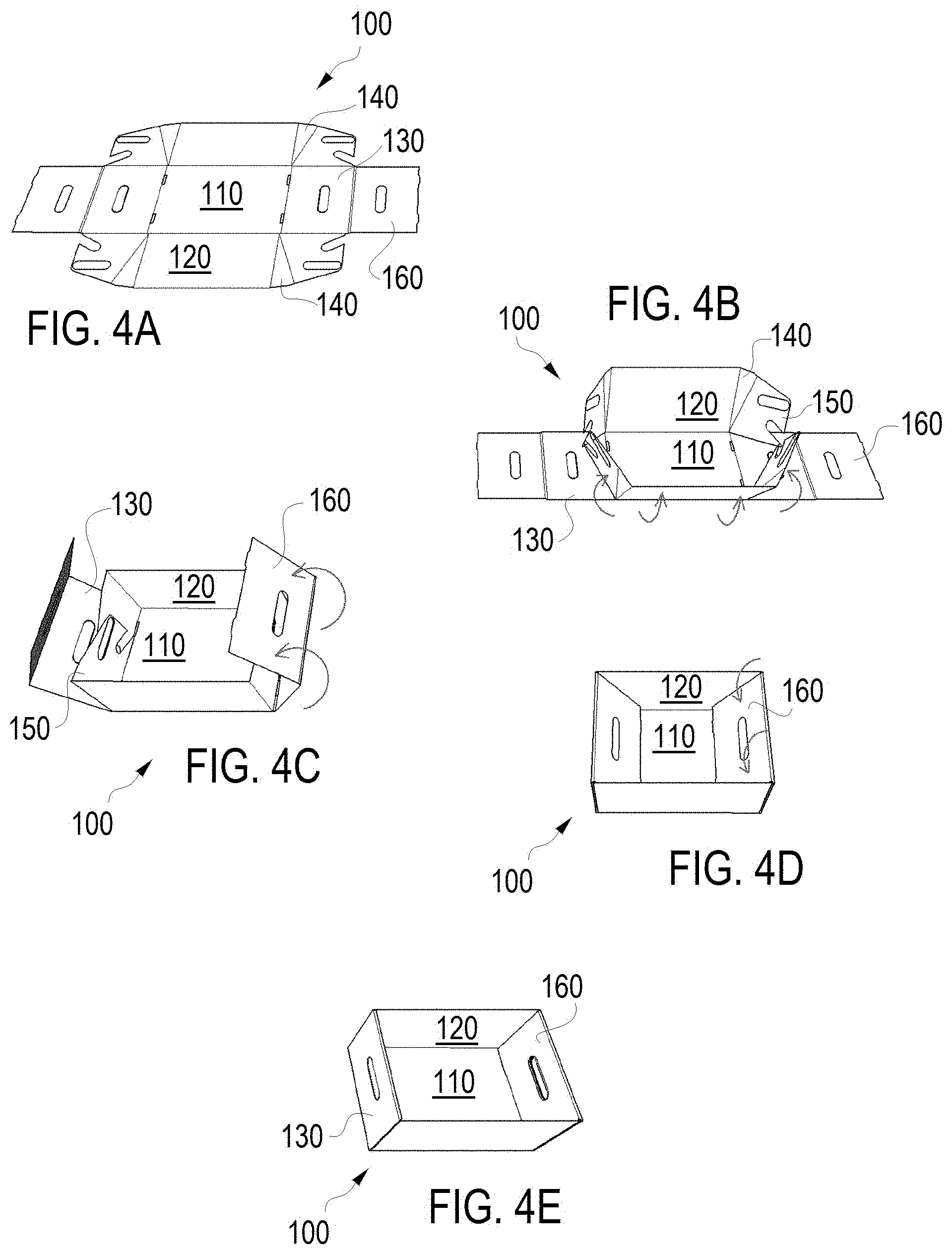
[0018] FIGS. 4A-4E sequentially illustrate forming the flat pack stackable four sided storage box of FIG. 1A from the flat die cut substrate of FIG. 3A;
[0019] FIG. 5 sequentially illustrates the conversion, from back to front, between the flat pack stackable four sided storage box of FIG. 1A to the eight sided nesting tote box of FIG. 1B;
[0020] FIG. 6 sequentially illustrates forming the flat pack storage box lid for the stackable four sided storage box of FIG. 1A from the flat die cut substrate of FIG. 3B;
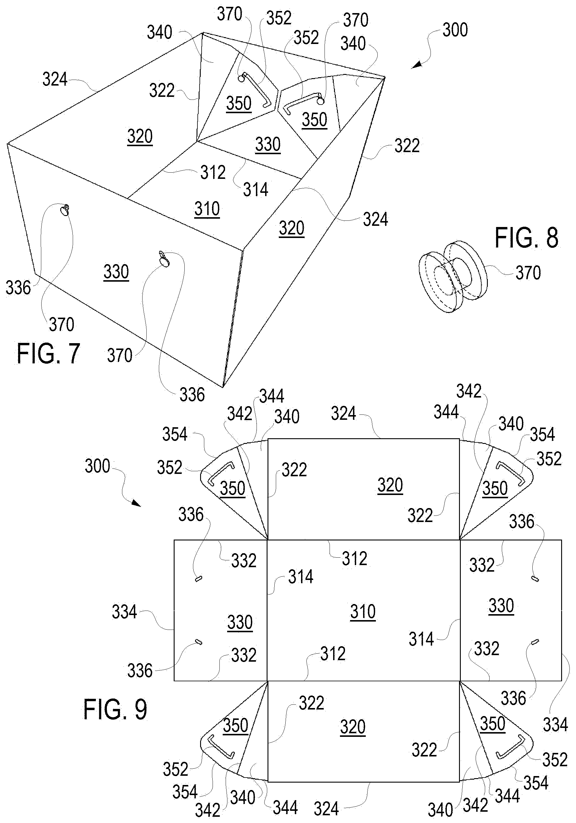
[0021] FIG. 7 is a perspective view of a flat pack stackable four sided storage box in accordance with a second embodiment of the present invention and shown without a lid and which storage box can convert to an eight sided nesting tote box;
[0022] FIG. 8 is a perspective view of a one piece double headed connecting stud for forming the flat pack stackable four sided storage box of FIG. 7;
[0023] FIG. 9 is a top plan view of a flat die cut substrate used in forming the flat pack stackable four sided storage box of FIG. 7;
[0024] FIG. 10 sequentially illustrates the conversion, from front to back, between the flat pack stackable four sided storage box of FIG. 7 to an eight sided nesting tote box; and
[0025] FIG. 11 is a schematic view which sequentially illustrates the conversion between a modified assembly of a flat pack stackable four sided storage box of FIG. 7 to an eight sided nesting tote box.
DESCRIPTION OF THE PREFERRED EMBODIMENTS
[0026] The present invention provides a flat pack box 100 and 300, specifically a stackable four sided storage box 100 or 300 that can expand to a larger containment size by converting to an eight sided nesting tote box 100 or 300, and vice-versa as shown in FIGS. 1 A and 1B in one embodiment (box 100) and in FIG. 7 in an alternative embodiment (box 300) of the present invention. The box 100 or 300 includes a lid 200 for use in the storage box mode and to facilitate stacking of the storage boxes as shown in FIG. 2A. The boxes 100 and 300 and lids 200 may be nested when in the tote box configuration as generally shown in FIG. 2A.
[0027] The flat pack box 100, aside from the lid 200, is formed from a die cut planar substrate or member such as cardboard, plastic, corrugated plastic cardboard or possibly other similar materials. The flat pack layout for the box 100 is shown in FIG. 3A and is helpful for illustrating the various components of the structure of the present invention. The lid 200 is also formed from a die cut planar substrate or member analogous to the layout of the other elements of the box 100 shown in FIG. 3A, and the lid 200 layout is shown in FIG. 3B
[0028] A base 110 forms the plan view outline of the storage box 100 and is shown as a rectangle. The rectangular base includes two parallel base longitudinal score lines 112 for the longitudinal sides 120 and two parallel base end score lines 114 for the outer end sides 130. Score lines are known in the art and can also be described or referenced as hinges, living hinges or fold lines. The base 110 includes two openings 116 along each base end score line 114 for receiving locking tabs 166 which help secure or maintain the box 100 in both deployed positions shown in FIGS. 1A and 1B.
[0029] The two opposed rectangular longitudinal sides 120 each have opposed end score lines 122 along the ends between the sides 120 and triangular sides 140 and top edges 124 defining a top surface for the box 100 upon which the lid 200 sits when attached to the storage box 100.
[0030] The two rectangular outer end sides 130 each have opposed cut lines 132 and a top score line 134 associated with the top surface for the box 100 upon which the lid 200 rests when attached to the storage box 100. Cut lines, as opposed to score lines, extend through the substrate, and cut lines 132 separate the end sides 130 from the material forming the moving conversion panels 150. Each rectangular outer end side 130 includes a cutline 136 around three sides of an oval handle opening and forming a locking tab 138.
[0031] The box 100 includes four triangular expansion sides 140 located adjacent the ends of the sides 120, with the triangular expansion sides 140 having a score line 142 between the side 140 and the conversion panel 150. Each triangular expansion side 140 has a top edge 144.
[0032] The box 100 includes four the moving conversion panels 150, each adjacent an expansion side 140. Each panel 150 includes an opening 152, a top edge 154 and a second expansion opening 156. The openings 152 and 156 are configured to selectively align with the handle opening formed by cut 136 and be locked into position with the tab 138.
[0033] The box 100 includes a pair of inner end sides 160 generally adjacent the end sides 130 with a score line 162 offset from score line 134 by a thickness adapted to accommodate folding the end sides 160 such that the sides 160 and 130 are on opposite sides of intervening panels 150 and sides 140 as discussed below. The sides 160 include opening 164 that aligns with the handle opening formed by cutline 136. The openings 164 are essentially the handle openings for the box 100.
[0034] FIGS. 4A-4E sequentially illustrate forming the flat pack stackable four sided storage box 100 of FIG. 1A from the flat die cut substrate of FIG. 3A. Essentially the longitudinal sides 120 are folded up along score lines 112 and the triangular expansion sides 140 and the conversion panels 150 are folded in along score lines 122 as shown in FIG. 4B. Then the outer end sides 130 are folded up along score line 114 and the inner end sides are folded back down over the intervening panels 150 and sides 140 along first score line 134 and then score line 162 as shown in FIGS. 4C and 4D. The tabs 166 are secured within openings 116 to complete the box. 100 as shown in FIG. 4E.
[0035] In the storage box position of FIGS. 1A, 2B and 4E the openings formed by cutline 136, the opening 152 and the opening 164 are aligned and the box may be locked into the four sided storage box position by pushing locking tab 138 through the openings 152 and 164 and folding it so it is parallel to the inner end side 160. The four exposed sides of the box will be lateral sides 120 and end sides 130 (the inner end sides 160 may be considered part of the outer end sides 130 forming a combined end side to the device.)
[0036] As noted above a key aspect to the invention is that the present invention provides a flat pack box 100 (and 300 discussed below), specifically a stackable four sided storage box 100 (or 300) that can convert to an eight sided nesting tote box 100 (or 300), and vice-versa as shown in FIGS. 1A and 1B in one embodiment (box 100) and in FIG. 7 in an alternative embodiment (box 300) of the present invention. Specifically for the box 100, FIG. 5 sequentially illustrates the conversion, proceeding from back to front, between the flat pack stackable four sided storage box 100 of FIG. 1A, and the eight sided nesting tote box 100 of FIG. 1B. Beginning with the box 100 locked in the storage box 100 configuration, the locking tab 138 is pushed back through the then aligned openings 164 and 152 to allow the conversion. The sides 120 are pulled laterally outwardly to fully expose the expansion sides 140. In the fully exposed position of the sides 140 the openings 156 and 164 will be aligned and the locking tab 138 can be pushed through openings 156 and 164 and folded to be parallel with the inner end side 160 to secure the box 100 into the now eight sided structure. At the same time as the tab is being pushed into position (or immediately following, because the user's hands will be in position engaging the ends 130) the ends 130 (and 160) are pulled outward. The outward pivoting movement of the ends 130 is allowed by the score lines 142 permitting a movement of the expansion panel 140 from a position parallel to the ends 130 and 160 and the panel 150 to a position angled relative to the ends 130, 160 and the panel 150. This forms the eight sided nesting tote box 100 in which all the sides 120, 130 (and 160), and 140 flare outwardly. In the first embodiment the edge 154 may abut against the inner end side 160 between the score lines 134 and 162 to act as a stop when pulling out or flaring out the sides 120. This built in stop by edge 154 against the top of the end side allows the easy alignment of the openings 156 and 164 in the fully flared out position. The process can easily be reversed to convert from the eight sided nesting tote box 100 of FIG. 1B to the stackable four sided storage box 100 of FIG. 1A.
[0037] The box 100 of the present invention includes a lid 200 configured to be secured on top of the box 100 when in the storage box configuration as generally shown in FIG. 2B. FIG. 3B is a top plan view of a flat die cut substrate used in forming the lid 200 for the flat pack stackable four sided storage box 100 of FIG. 2B and the eight sided nesting tote box lids of FIG. 2A. The lid 200 is formed essentially as a shorter version of the remainder of the box 100 shown in FIGS. 1A and 1s sized to fit around the top of the box as shown. The lid 200 converts between the "storage box" configuration and the eight sided nesting tote box lids of FIG. 2A in a similar fashion as the base or storage component of the box 100.
[0038] A top 210 forms the plan view outline of the lid 200 for the storage box 100 and is shown as a rectangle. The rectangular top 210 includes two parallel score lines 212 for the longitudinal sides 220 and two parallel score lines 214 for the outer end sides 230. The top 210 includes two openings 216 along each score line 214 for receiving locking tabs 266 which help secure the lid 200 of the box 100 in a deployed position shown in FIGS. 2A and 2B.
[0039] The two opposed rectangular longitudinal sides 220 each have opposed end score lines 222 along the ends between the sides 220 and triangular sides 240 and bottom edges 124. The two rectangular outer end sides 230 each have opposed cut lines 232 and a top score line 234 associated with the bottom edge for the lid 200 of the box 100. Cut lines 232 separate the end sides 230 from the material forming the moving conversion panels 250. Each rectangular outer end side 230 includes a cut line 236 around three sides of a semi-circular opening and forming a locking tab 238.
[0040] The lid 200 includes four triangular expansion sides 240 located adjacent the ends of the sides 220, with the triangular expansion sides 240 having a score line 242 between the side 240 and the conversion panel 250. Each triangular expansion side 240 has a top edge 244. The lid 200 includes four the moving conversion panels 250, each adjacent an expansion side 240. Each panel 250 includes an opening 252, a top edge 254. The opening 252 is configured to selectively align with the opening formed by cut 236 and be locked into position with the tab 238 when used as a storage box lid.
[0041] The lid 200 includes a pair of inner end sides 260 generally adjacent the end sides 230 with a score line 262 offset from score line 234 by a thickness adapted to accommodate folding the end sides 260 such that the sides 260 and 230 are on opposite sides of intervening panels 250 and sides 240 as discussed below. The sides 260 include opening 264 that aligns with the opening formed by cutline 236.
[0042] FIG. 6 sequentially illustrate forming the flat pack stackable four sided lid 200 for the storage box 100 of FIG. 2B from the flat die cut substrate of FIG. 3B. Essentially the longitudinal sides 220 are folded up along score lines 212 and the triangular expansion sides 240 and the conversion panels 250 are folded in along score lines 222. Then the outer end sides 230 are folded up along score line 214 and the inner end sides are folded back down over the intervening panels 250 and sides 240 along first score line 234 and then score line 262. The tabs 266 are secured within openings 216 to complete the assembly of the lid 200.
[0043] With the lid 200 in position for use as a lid 200 for storage box 100 as shown in FIG. 2B, the openings formed by cutline 236, the opening 252 and the opening 264 are aligned and the lid 200 may be locked into the "four sided storage box" position by pushing locking tab 238 through the openings 252 and 264 and folding it so it is parallel to the inner end side 260. The four exposed sides of the lid will be lateral sides 220 and end sides 230 (the inner end sides 260 may be considered part of the outer end sides 230 forming a combined end side to the device.)
[0044] The lid 200 can convert to an eight sided nesting tote box, and vice-versa as shown essentially in the same manner as the storage portion of the box discussed above. Beginning with the lid 200 locked in the position as a lid for the storage box 100 configuration, the locking tab 238 is pushed back through the then aligned openings 264 and 252 to allow the conversion. The sides 220 are pulled laterally outwardly to fully expose the expansion sides 240. The lid 200 as shown differs from the storage component of the box in that there is no method of locking the lid 200 in the eight sided nesting box configuration. Such a locking structure could be added if needed, but the primary purpose for conversion of the lid 200 is nesting as shown in FIG. 2A. An outward pivoting movement of the ends 230 following full deployment of the sides 240 is allowed by the score lines 242 permitting a movement of the expansion panel 240 from a position parallel to the ends 230 and 260 and the panel 250 to a position angled relative to the ends 230, 260 and the panel 250. This forms the eight sided nesting tote box structure in which all the sides 220, 230 (and 260), and 240 flare outwardly. The edge 254 may abut against the inner end side 160 between the score lines 234 and 262 to act as a stop when pulling out or flaring out the sides 220. This built in stop by edge 254 against the end side allows the easy positioning to the fully flared out position. The process can easily be reversed to convert from the eight sided nesting tote box lid of FIG. 2A to the lid for the stackable four sided storage box 100 of FIG. 2B.
[0045] FIG. 7 is a perspective view of a flat pack stackable four sided storage box 300 in accordance with a second embodiment of the present invention and shown without a lid and which storage box 300 can convert to an eight sided nesting tote box 300 as generally shown in FIG. 10.
[0046] FIG. 9 is a top plan view of a flat die cut substrate used in forming the flat pack stackable four sided storage box 300 of FIG. 7. The flat die cut substrate may also be assembled in a modified version in accordance with the boxes 300 shown in FIG. 11 wherein the expansion sides 340 and conversion panels 350 are on the outer side of the end sides 330. The box 300 include components analogous to box 100 discussed above and can utilize the lid 200 discussed above. These analogous elements includes a base 310 which forms the plan view outline of the storage box 300. The base 310 includes two parallel score lines 312 for the longitudinal sides 320 and two parallel score lines 314 for the outer end sides 330.
[0047] The base 310 does not include openings along each score line 314 (analogous to the opening 116) for receiving locking tabs (not present in this design) because the box 300 uses one piece double headed connecting studs 370, one of which is shown in detail in FIG. 8, to secure the box 300 in a deployed positions as detailed below.
[0048] The two opposed rectangular longitudinal sides 320 each have opposed end score lines 322 along the ends between the sides 320 and triangular sides 340 and top edges 324 defining a top surface for the box 300 upon which the lid 200 sits when attached to the storage box 300. The end sides 330 each have opposed cut lines 332 and a top cutline 234 associated with the top surface for the box 300 upon which the lid 200 rests when attached to the storage box 100. The top cut line 334 is opposed to score lines 134 in the embodiment of FIG. 1 because the box 300 does not have an analogous element to the inner side 160. Each rectangular end side 330 includes a cut lines 236 around an oval slot that receives one piece double headed connecting stud 370, shown in FIG. 8, for securing the box 100 together and allowing it to move between operative positions. With the stud 370 in the lower portion of the oval formed by cutline 336 the box 300 is locked into the operative position and with the stud lifted to the upper portion the box 300 is allowed to transition.
[0049] The box 300 includes four triangular expansion sides 340 located adjacent the ends of the sides 320, with the triangular expansion sides 340 having a score line 342 between the side 340 and the conversion panel 350. Each triangular expansion side 340 has a top edge 344. The box 300 includes four the moving conversion panels 350, each adjacent an expansion side 340. Each panel 350 includes a slot opening 352 with two downward detent positions, a top edge 354.
[0050] In the assembly of the box 300 the longitudinal sides 320 are folded up along score lines 312 and the triangular expansion sides 340 and the conversion panels 350 are folded in along score lines 322. Then the end sides 330 are folded up along score line 314. The studs 370 are secured within openings 336 and the openings 352 to complete the box 300.
[0051] In the storage box position the studs 370 are in the detent of opening or slot 352 that is closest to the sides 320. The four exposed sides of the box 300 will be lateral sides 320 and end sides 330. FIG. 10 sequentially illustrates the conversion, proceeding from front to back, between the flat pack stackable four sided storage box 300 and the eight sided nesting tote box 300. FIG. 11 sequentially illustrates the conversion between the modified assembly of the flat pack stackable four sided storage box 300 and the eight sided nesting tote box 300 (wherein the end sides 330 are inward of the panels 350 and sides 340). The assembly and operation between FIGS. 10 and 11 are essentially the same. Beginning with the box 300 locked in the storage box 100 configuration, the stud 370 are pushed up to the top of the opening 336 out of the detent in slot 356 to allow the conversion. The sides 320 are pulled laterally outwardly to fully expose the expansion sides 340. In the fully exposed position of the sides 340 studs 370 can be returned to the lower portion of the opening 336 within the detent in the distal end of the slot 356 farthest from the sides 320 to secure the box 300 into the now eight sided structure. Then the ends 330 are pulled outward. The outward pivoting movement of the ends 330 is allowed by the score lines 342 permitting a movement of the expansion panel 340 from a position parallel to the ends 330 and the panel 350 to a position angled relative to the ends 330 and the panel 350. This forms the eight sided nesting tote box in which all the sides 320, 330 and 340 flare outwardly.
[0052] While this invention has been particularly shown and described with references to the preferred embodiments thereof, it will be understood by those skilled in the art that various changes in form and details may be made therein without departing from the scope of the invention.
* * * * *
D00000
D00001
D00002
D00003
D00004
D00005
D00006
XML
uspto.report is an independent third-party trademark research tool that is not affiliated, endorsed, or sponsored by the United States Patent and Trademark Office (USPTO) or any other governmental organization. The information provided by uspto.report is based on publicly available data at the time of writing and is intended for informational purposes only.
While we strive to provide accurate and up-to-date information, we do not guarantee the accuracy, completeness, reliability, or suitability of the information displayed on this site. The use of this site is at your own risk. Any reliance you place on such information is therefore strictly at your own risk.
All official trademark data, including owner information, should be verified by visiting the official USPTO website at www.uspto.gov. This site is not intended to replace professional legal advice and should not be used as a substitute for consulting with a legal professional who is knowledgeable about trademark law.