Hovering Aircraft Belly Bar Clasp
Winfree; Gordon Brent ; et al.
U.S. patent application number 16/931268 was filed with the patent office on 2020-11-05 for hovering aircraft belly bar clasp. The applicant listed for this patent is Quanta Associates, LP. Invention is credited to Mike Patton, Gordon Brent Winfree.
| Application Number | 20200346754 16/931268 |
| Document ID | / |
| Family ID | 1000004959932 |
| Filed Date | 2020-11-05 |


| United States Patent Application | 20200346754 |
| Kind Code | A1 |
| Winfree; Gordon Brent ; et al. | November 5, 2020 |
Hovering Aircraft Belly Bar Clasp
Abstract
A belly bar method and apparatus use to attach, carry and release external cargo from a hovering aircraft. The belly bar apparatus has articulated tubing tool connected to an airframe of the hovering aircraft at a first mounting end and at a second mounting end. The articulated tubing tool has a first external catch and a second external catch mounted on the articulated tubing tool. The first external catch is manually configured for optional attach, carry and release of the external cargo via the cyclic. The second external catch is electronically configured for optional attach, carry and release of the external cargo proximate the collective.
| Inventors: | Winfree; Gordon Brent; (Naples, FL) ; Patton; Mike; (Aurora, OR) | ||||||||||
| Applicant: |
|
||||||||||
|---|---|---|---|---|---|---|---|---|---|---|---|
| Family ID: | 1000004959932 | ||||||||||
| Appl. No.: | 16/931268 | ||||||||||
| Filed: | July 16, 2020 |
Related U.S. Patent Documents
| Application Number | Filing Date | Patent Number | ||
|---|---|---|---|---|
| 16597630 | Oct 9, 2019 | 10717530 | ||
| 16931268 | ||||
| 15152785 | May 12, 2016 | 10472065 | ||
| 16597630 | ||||
| 62160107 | May 12, 2015 | |||
| Current U.S. Class: | 1/1 |
| Current CPC Class: | B64D 1/22 20130101; B64C 27/04 20130101; H02G 1/02 20130101 |
| International Class: | B64D 1/22 20060101 B64D001/22 |
Claims
1. A belly bar clasping apparatus for use to attach, carry and release an external cargo from a hovering aircraft, the apparatus comprising: an articulated tubing tool connected to an airframe of the hovering aircraft at a first mounting end and at a second mounting end; wherein said articulated tubing tool comprises a first external catch on said articulated tubing tool and a second external catch on said articulated tubing tool; and wherein said first external catch and said second external catch are respectively configured for optional attach, carry and release of the external cargo.
2. The belly bar clasping apparatus according to claim 1, wherein said articulated tubing tool further comprises a bent shaft component continuing to a connector shaft component; and wherein said first external catch and said second external catch are mounted to the connector shaft component.
3. The belly bar clasping apparatus according to claim 2, further comprising a manually actuated cable connecting said first external catch to a cyclic located in the hovering aircraft; wherein said first external catch is configured for manual release activated by a manually actuated lever located on the cyclic; and a communication line for connecting an electronic hook actuator on said second external catch to a button proximate a collective located in the hovering aircraft.
4. The belly bar clasping apparatus according to claim 2, wherein the external cargo is connected via a plurality of straps to said first external catch and said second external catch.
5. The belly bar clasping apparatus according to claim 2, wherein the connector shaft component comprises: a pin for attaching to a first external catch mount proximate the first mounting end; a mid-shaft component continuing to said pin; a hook swivel adjacent the mid-shaft component; and a lock collar for securing said hook swivel to the mid-shaft component.
6. The belly bar clasping apparatus according to claim 5, wherein the connector shaft component further comprises a swivel stop collar attached to said bent shaft component and mounted in interfering relationship with said hook swivel.
7. The belly bar clasping apparatus according to claim 6, wherein said hook swivel comprises: a journal which rotates on said bent shaft component; a secondary hook attachment flange positioned on the journal; and a first travel stop on the journal and in interfering relationship with said swivel stop collar.
8. The belly bar clasping apparatus according to claim 7, further comprising a hinge connected to a mounting end of said bent shaft component via a hinge pin; and a jackpoint pin for connecting the hinge to the hovering aircraft.
9. The belly bar clasping apparatus according to claim 7, further comprising a spacer for connection to said pin; and wherein the spacer is for connecting the articulated tubing tool to the hovering aircraft.
10. The belly bar clasping apparatus according to claim 2, wherein the connector shaft component comprises: a pin continuing from the connector shaft component for attaching to a first external catch mount proximate the first mounting end; wherein said second external catch is adjacent the connector shaft component; a lock collar for securing said second external catch to the connector shaft component; and wherein said first external catch is adjacent to the first external catch mount.
11. The belly bar clasping apparatus according to claim 2, wherein the connector shaft component comprises: a connection for attaching to a first external catch mount proximate the first mounting end; a mid-shaft component continuing to said connection; a hook swivel adjacent the mid-shaft component; and a lock collar for securing said hook swivel to the mid-shaft component.
12. The belly bar clasping apparatus according to claim 2, wherein the connector shaft component comprises: a connection continuing from the connector shaft component for attaching to a first external catch mount proximate the first mounting end; wherein said second external catch is adjacent the connector shaft component; a lock collar for securing said second external catch to the connector shaft component; and wherein said first external catch is adjacent to the first external catch mount.
13. A belly bar clasping apparatus for use to attach, carry and release an external cargo from a hovering aircraft, the apparatus comprising: an articulated tubing tool connected to an airframe of the hovering aircraft at a first mounting end and at a second mounting end; wherein said articulated tubing tool comprises a first external catch on said articulated tubing tool and a second external catch on said articulated tubing tool; wherein said first external catch and said second external catch are respectively configured for optional attach, carry and release of the external cargo; wherein said articulated tubing tool further comprises a bent shaft component continuing to a connector shaft component; wherein said first external catch and said second external catch are mounted to the connector shaft component; wherein the connector shaft component comprises a pin continuing from the connector shaft component for attaching to a first external catch mount proximate the first mounting end; wherein said second external catch is adjacent the connector shaft component; a lock collar for securing said second external catch to the connector shaft component; and wherein said first external catch is adjacent to the first external catch mount.
14. The belly bar clasping apparatus according to claim 13, further comprising a manually actuated cable connecting said first external catch to a cyclic located in the hovering aircraft; wherein said first external catch is configured for manual release activated by a manually actuated lever located on the cyclic; and a communication line for connecting an electronic hook actuator on said second external catch to a button proximate a collective located in the hovering aircraft.
15. The belly bar clasping apparatus according to claim 13, wherein the external cargo is connected via a plurality of straps to said first external catch and said second external catch.
16. A method of releasing an external cargo from a hovering aircraft, comprising the steps of: attaching a first external catch to the external cargo; attaching a second external catch to the external cargo; releasing a first external catch via a cyclic mounted controls in the hovering aircraft; and releasing a second external catch via collective mounted controls of the hovering aircraft.
17. The method according to claim 16, wherein said step of releasing the first external catch is performed manually or electrically; and wherein said step of releasing the second external catch is performed electrically and/or manually.
18. The method according to claim 16, wherein said steps of attaching the first external catch and attaching the second external catch are accomplished via mounting a belly bar clasp below an airframe belly of the hovering aircraft.
Description
STATEMENTS REGARDING FEDERALLY SPONSORED RESEARCH OR DEVELOPMENT
[0001] Not Applicable.
NAMES OF THE PARTIES TO A JOINT RESEARCH AGREEMENT
[0002] Not Applicable.
REFERENCE TO A "SEQUENCE LISTING", A TABLE, OR A COMPUTER PROGRAM
[0003] Not Applicable.
BACKGROUND
Technical Field
[0004] The disclosure relates to devices and techniques for attaching, releasing and carrying external loads from a helicopter or other hovering flight vehicle. Such helicopters are used, for example, in techniques to install, repair and maintain electric transmission lines (a high voltage environment).
[0005] Current or conventional helicopter operations which utilize human external cargo to install, repair and/or maintain, for example, remote utility lines do so by the way a "belly band" (a strap which is fitted through the cabin of the helicopter encircling the helicopter that provides a secondary point of attachment and release outside of and below the helicopter). Release is achieved with an integrated release mechanism. The release mechanism requires the pilot to release the flight controls in order to activate the release mechanism for the human external cargo. Within the context of the foregoing consider that the reaction time of the operator is critical to successful operation of the release mechanism in an emergency situation while piloting or maneuvering the helicopter. Further one must also be concerned with the inadvertent release of the cargo load (human or otherwise).
SUMMARY
[0006] A belly bar method and apparatus used to catch human external cargo in the event of a failure or unintended release from the primary attachment (i.e. cargo hook, etc.) and provide the temporary emergency carriage and provide a system of release of the human external cargo from a hovering aircraft. The belly bar apparatus has articulated tubing tool connected to an airframe of the hovering aircraft at a first mounting end and at a second mounting end. The articulated tubing tool has a secondary external catch mounted on the articulated tubing tool. The primary external catch (aircraft mounted cargo hook) is configured for attachment, carriage and manual or electronic release of the external cargo via the cyclic mounted controls. The secondary external catch is configured for temporary emergency carriage and electronic and/or manual release of the external cargo via the collective mounted controls.
[0007] All pins described herein may take various forms as known to one having ordinary skill in the art.
BRIEF DESCRIPTION OF THE DRAWINGS
[0008] The embodiments may be better understood, and numerous objects, features, and advantages made apparent to those skilled in the art by referencing the accompanying drawings. These drawings are used to illustrate only typical embodiments of this invention, and are not to be considered limiting of its scope, for the invention may admit to other equally effective embodiments. The figures are not necessarily to scale and certain features and certain views of the figures may be shown exaggerated in scale or in schematic in the interest of clarity and conciseness.
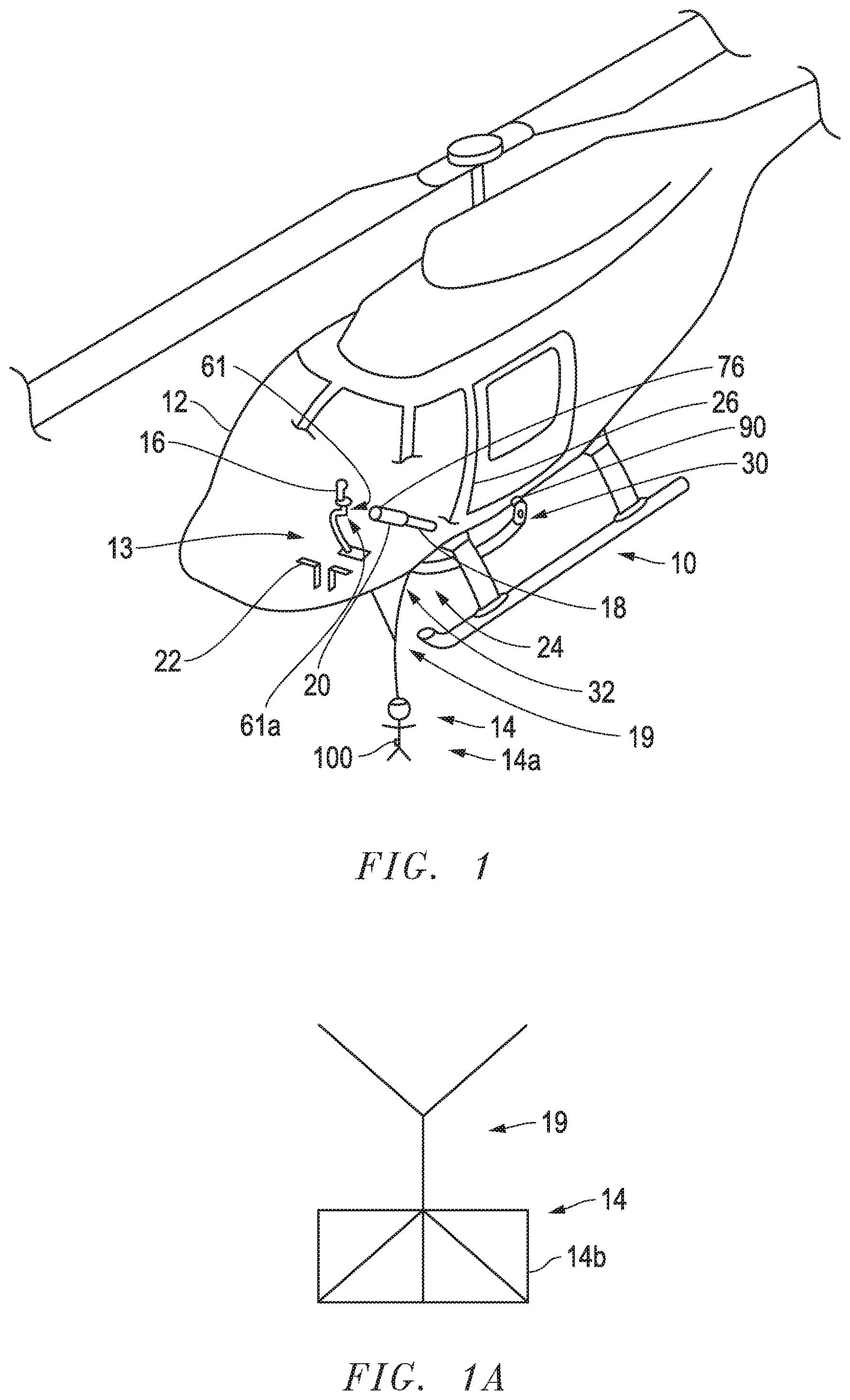
[0009] FIG. 1 depicts a schematic diagram of a hovering aircraft with a belly bar clasping system according to one embodiment.
[0010] FIG. 1A depicts another embodiment showing other external cargo which may be carried by the hovering aircraft with a belly bar clasping system of FIG. 1.
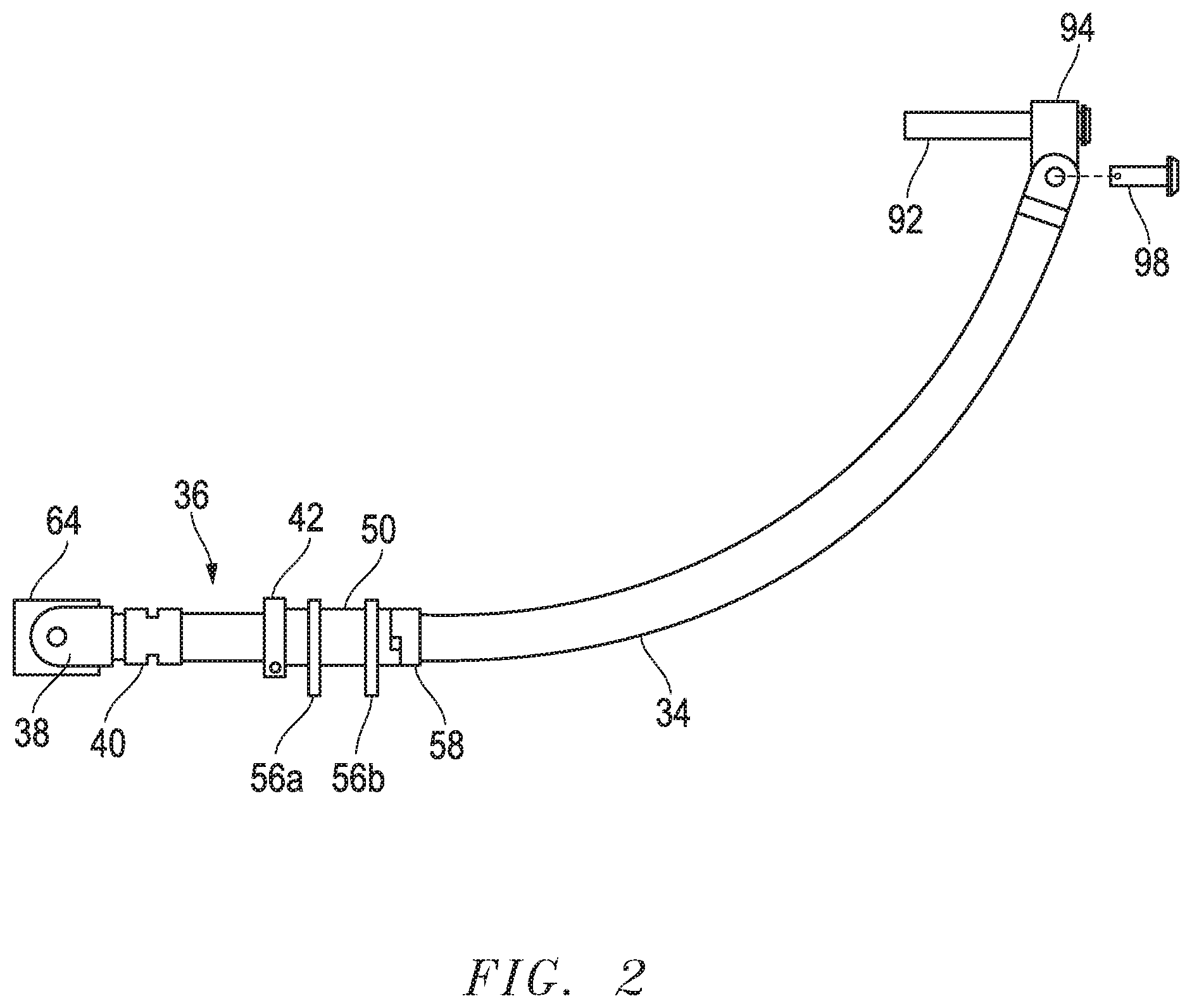
[0011] FIG. 2 depicts an elevation view of a belly bar clasp according to one embodiment.
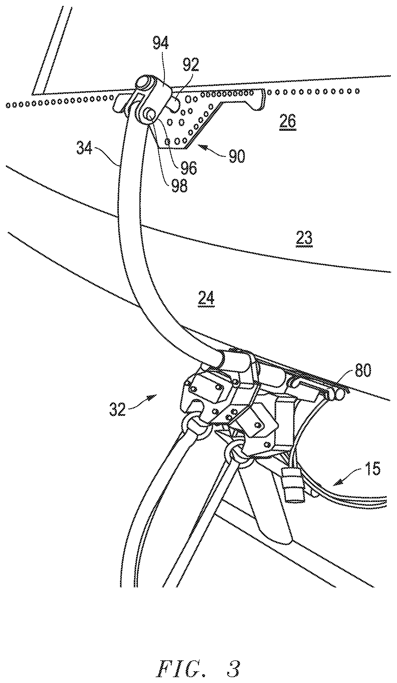
[0012] FIG. 3 depicts a perspective view of a portion of the belly bar clasping system mounted to the hovering aircraft according to one embodiment.
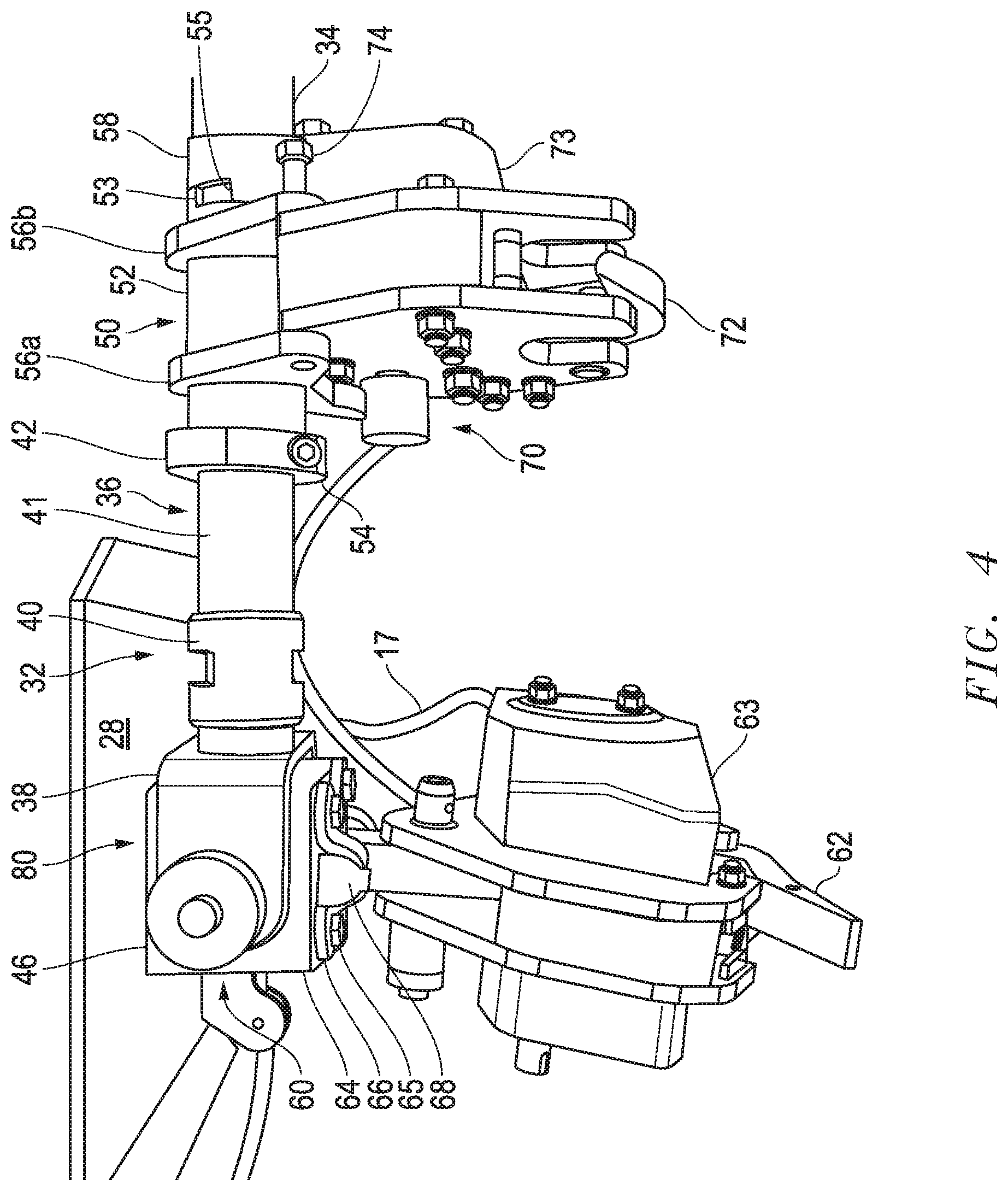
[0013] FIG. 4 depicts a perspective view of a portion of the belly bar clasping system mounted below the hovering aircraft according to one embodiment.
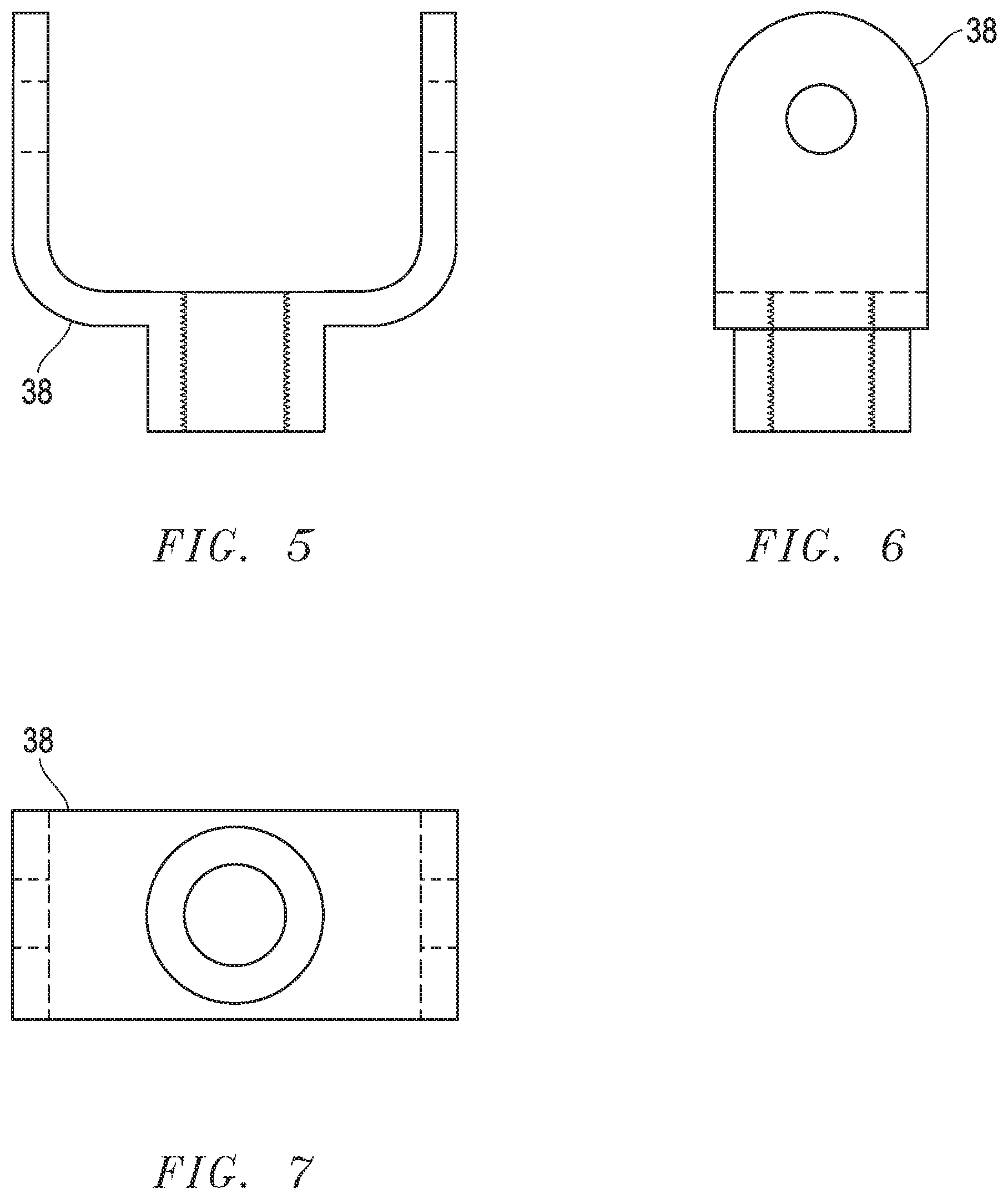
[0014] FIG. 5 depicts a top view of one embodiment of a fork.
[0015] FIG. 6 depicts a side view of the fork embodiment shown in FIG. 5.
[0016] FIG. 7 depicts an end view of the fork embodiment shown in FIG. 5.
[0017] FIG. 8 depicts a side view of one embodiment of a connector/jam nut.
[0018] FIG. 9 depicts an end view of the connector/jam nut embodiment shown in FIG. 8.
[0019] FIG. 10 depicts a side view of one embodiment of a mid-shaft.
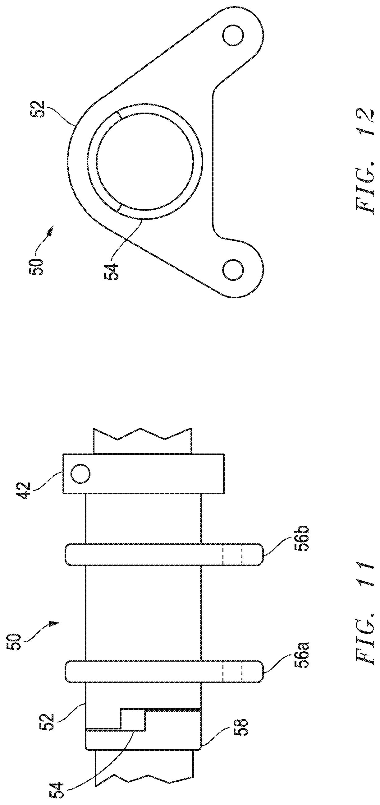
[0020] FIG. 11 depicts a side view of one embodiment of a hook swivel.
[0021] FIG. 12 depicts an end view of the hook swivel embodiment shown in FIG. 11.
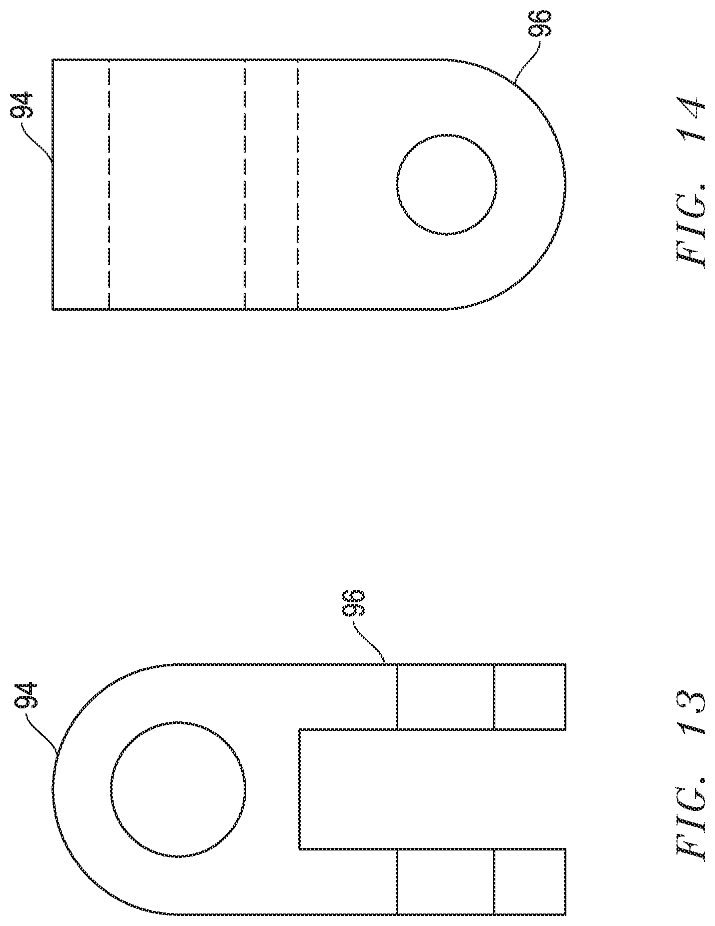
[0022] FIG. 13 depicts a side view of one embodiment of a hinge.
[0023] FIG. 14 depicts an end view of the hinge embodiment shown in FIG. 13.
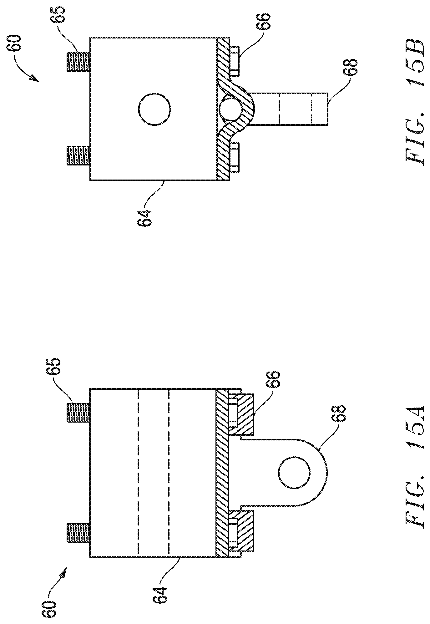
[0024] FIGS. 15A & 15B depict elevation views of an embodiment of a primary external catch mount with spacer block, saddle and a pivot link.
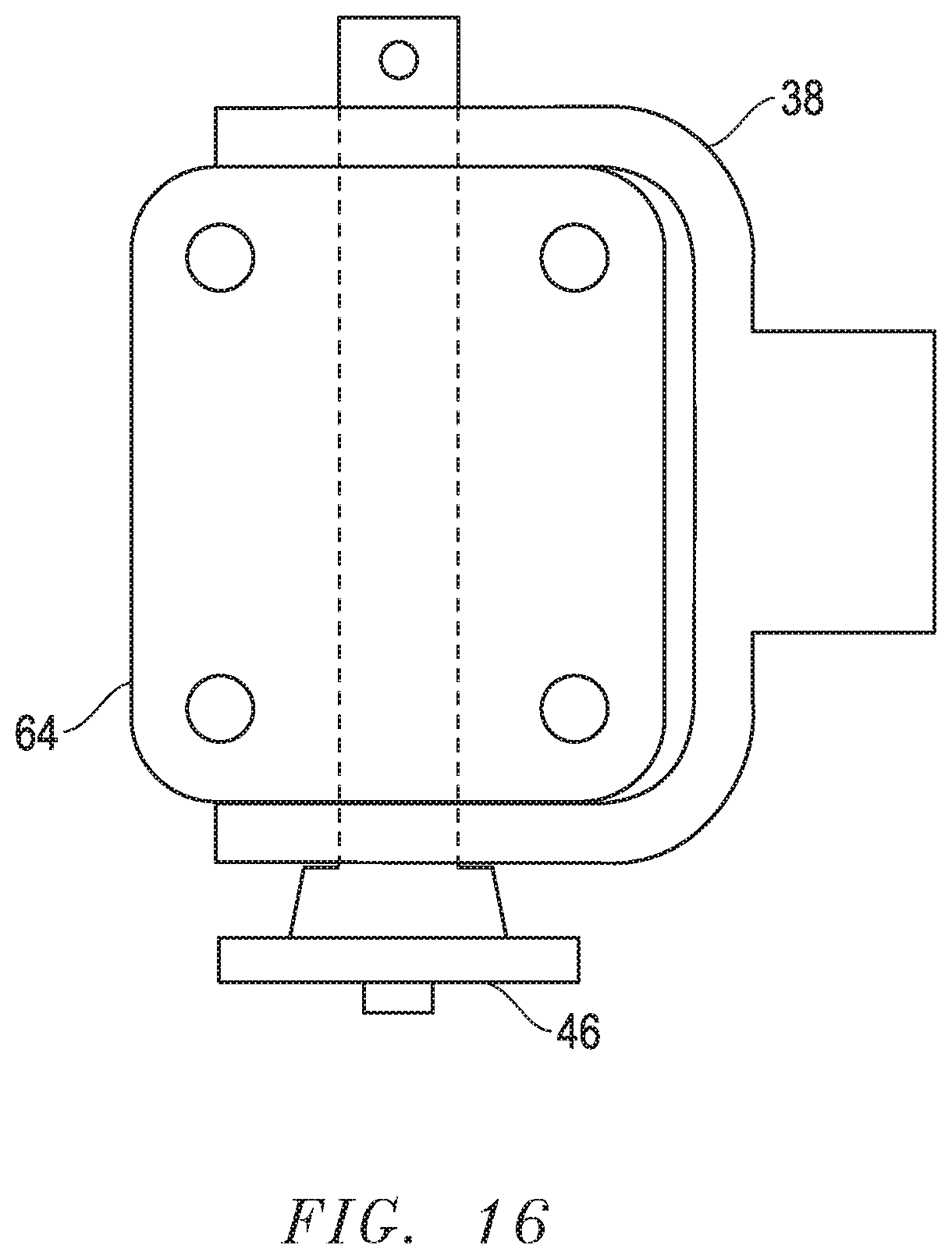
[0025] FIG. 16 depicts a bottom view of an embodiment of a fork connected to a spacer.
DESCRIPTION OF EMBODIMENT(S)
[0026] The description that follows includes exemplary apparatus, methods, techniques, and instruction sequences that embody techniques of the inventive subject matter. However, it is understood that the described embodiments may be practiced without these specific details.
[0027] FIG. 1 shows a schematic diagram depicting a hovering aircraft belly bar clasping system 10. In an exemplary embodiment the hovering aircraft belly bar clasping system 10 generally includes a hovering aircraft or helicopter 12 and a belly bar clasping system 30. The helicopter 12 totes the belly bar clasp 30 (which may also be referred to as a "BELLY BAR") which may be used to catch and temporarily carry and provide a release for external cargo 14. Such external cargo 14 includes human external cargo (e.g. workers) 14a and/or other external cargo 14b (FIG. 1A). Human external cargo workers 14a may be, for example, linemen, pilots, emergency rescue workers, and the like. The workers 14a may, for example, work with, near, repair, maintain and/or install electric transmission lines.
[0028] The exemplary helicopter 12 has a control center 13 and as shown has a cyclic 16, a collective 18 including a throttle 20, pedals 22, and an airframe 23 including an airframe belly (i.e. underside) 24 which merges into airframe sidewalls 26. The belly bar clasping system 30 mounts to the helicopter 12. The external cargo 14 may be attached to, carried by and/or released from the belly bar clasping system 30 via straps 19 or the like.
[0029] Now referring to FIGS. 1-4, the belly bar clasping system 30 in an exemplary embodiment generally has an articulated tubing tool 32, a second or secondary external catch 72, a first mounting end 80 and a second mounting end 90. The belly bar clasping system 30 mounts under the airframe belly 24 at the first mounting end 80 and at the second mounting end 90 proximate the airframe sidewall 26 or region where the airframe belly 24 merges into the airframe sidewall 26.
[0030] The articulated tubing tool 32 in the exemplary embodiment shown generally has bent shaft (tubing or bar) 34, a connector shaft (tube or bar) 36 and a second or secondary external catch mount 70. The entire articulated tubing tool 32 or various components may be made of metal (preferably steel or an alternative lighter weight metal) or be filament wound, compression molded, transfer molded, cast, machined from a plastic, composite, metal, elastomer, `3D printed` or any combination thereof.
[0031] In the embodiment shown the connector shaft 36 has a fork 38, a connector/jam nut 40, a mid-shaft (tube or rod) 41, a lock collar/connector 42 and a hook swivel 50. The fork 38 (shown in FIGS. 5-7) is attached via, for example, a pin 46, to the first external catch mount 60 proximate the first mounting end 80. The connector/jam nut 40 (shown in FIGS. 8-9) secures the mid-shaft or rod 41 (shown in FIG. 10) to the fork 38. The lock collar/connector 42 secures the hook swivel 50 (shown in FIGS. 11-12) around the mid-shaft 41. The mid-shaft 41 extends through the inside of the hook swivel 50 and connects to the bent shaft 34. The hook swivel 50 pivots around the bent shaft 34. The journal 52 includes a first travel stop 53 and the swivel stop collar 58 includes a second travel stop 55 that limits rotation of the journal 52 about mid-shaft 41. In one exemplary embodiment the rotation is limited to about thirty degrees although other angles desirable to one using second external catch mount 70 may be implemented. The hook swivel 50 includes two secondary hook attachments/mounting flanges 56a & 56b for connecting the journal 52 to the second external catch mount 70 via pin(s) 74.
[0032] The bent shaft 34 connects to the second mounting end 90. The second mounting end 90 includes a jackpoint pin 92 (see FIG. 2). A hinge 94 (shown in FIGS. 13-14) is joined over the jackpoint pin 92 and sidewalls 96 of the hinge 94 are connected to the bent shaft 34 via a hinge pin 98 (see FIG. 2).
[0033] Referring to FIGS. 2, 4, & 15-16, the first external catch mount 60 includes a spacer 64 (pinned to fork 38) joined by bolts 65 via a mounting plate 28 to the airframe belly 24 at first end 80. Saddles 66 are attached to the spacer 64 via bolts 65. The saddles 66 hold a pivot link or pin 68 joining the spacer 64 to the first external catch 62.
[0034] First external catch 62 is generally a hooking device and has a hook actuator 63 in communication with the control center 13 via manually actuated cable 17 (alternatively communication lines 15, hard wired as shown The first external catch 62 may be an off the shelf commercially available catch such as, for example, those available from Breeze-Eastern Corporation of Whippany, N.J., USA.
[0035] Second external catch 72 is generally a back-up hooking device and has a hook actuator 73 in communication with the control center 13 via communication lines 15 (hard wired as shown but may also be wireless including transmitter(s)/receiver(s)). The second external catch 72 may also be an off the shelf commercially available catch such as, for example, those available from Mechanical Specialties of Olympia, Wash., USA.
[0036] In alternative embodiments the human external cargo workers 14a may have a controller 100 linked (e.g. via wireless or the like) to the control center 13 and or hook actuator 63 to allow the human external cargo workers 14a to activate open or release the first external catch 62 and/or second external catch 72 in an emergency situation.
[0037] In one working example for use of the hovering aircraft belly bar clasping system 10, the first external catch 62 may be the primary catch and the second external catch 72 may be a back-up catch (both must be released for release of the external cargo 14). The first external catch 62 is a manual release system activated by a manually actuated handle, lever, button (or the like) 61 located on the cyclic 16 and a control cable (manually actuated cable 17) connecting the handle, lever, button (or the like) 61 to the first external catch 62 by way of the hook actuator 63. A pull safety pin 61a may also be implemented into the manually actuated handle, button (or the like) located on the cyclic 16. The second external catch 72 (in this case a back-up system) is an electronically activated release system with a protected (recessed) button 76 proximate the collective 18, relay lines (communication wire 15), an electronic hook actuator 73 to actuate release of second external catch 72. The electronic circuit may normally be de-energized requiring power to actuate the electronic hook actuator 73 for release of the second external catch 72.
[0038] While the embodiments are described with reference to various implementations and exploitations, it will be understood that these embodiments are illustrative and that the scope of the inventive subject matter is not limited to them. Many variations, modifications, additions and improvements are possible.
[0039] Plural instances may be provided for components, operations or structures described herein as a single instance. In general, structures and functionality presented as separate components in the exemplary configurations may be implemented as a combined structure or component. Similarly, structures and functionality presented as a single component may be implemented as separate components. These and other variations, modifications, additions, and improvements may fall within the scope of the inventive subject matter.
* * * * *
D00000
D00001
D00002
D00003
D00004
D00005
D00006
D00007
D00008
D00009
D00010
XML
uspto.report is an independent third-party trademark research tool that is not affiliated, endorsed, or sponsored by the United States Patent and Trademark Office (USPTO) or any other governmental organization. The information provided by uspto.report is based on publicly available data at the time of writing and is intended for informational purposes only.
While we strive to provide accurate and up-to-date information, we do not guarantee the accuracy, completeness, reliability, or suitability of the information displayed on this site. The use of this site is at your own risk. Any reliance you place on such information is therefore strictly at your own risk.
All official trademark data, including owner information, should be verified by visiting the official USPTO website at www.uspto.gov. This site is not intended to replace professional legal advice and should not be used as a substitute for consulting with a legal professional who is knowledgeable about trademark law.