Hot Water System
TING; TAILAI
U.S. patent application number 16/393552 was filed with the patent office on 2020-10-29 for hot water system. The applicant listed for this patent is TAILAI TING. Invention is credited to TAILAI TING.
| Application Number | 20200340686 16/393552 |
| Document ID | / |
| Family ID | 1000004081332 |
| Filed Date | 2020-10-29 |


| United States Patent Application | 20200340686 |
| Kind Code | A1 |
| TING; TAILAI | October 29, 2020 |
Hot Water System
Abstract
A hot water system includes an electrical water heater for instantly heating up cold water running in pipe. The electrical water heater is installed with a bypass switch for users to switch off the system if necessary. To prevent water damage caused by leaking, a pressure relief valve is installed on the outgoing water pipe of the water heater and a drain saddle valve is installed on the drain pipe. Both valves are connected with a water hose. The hot water system will save a lot of time and clean water while waiting for hot water coming from the main water heater. The system allows the user to access instant hot water safely and achieve a much easier and more comfortable life.
| Inventors: | TING; TAILAI; (POMONA, CA) | ||||||||||
| Applicant: |
|
||||||||||
|---|---|---|---|---|---|---|---|---|---|---|---|
| Family ID: | 1000004081332 | ||||||||||
| Appl. No.: | 16/393552 | ||||||||||
| Filed: | April 24, 2019 |
| Current U.S. Class: | 1/1 |
| Current CPC Class: | F24D 19/1054 20130101; F25B 2600/2525 20130101; F25B 2600/2519 20130101 |
| International Class: | F24D 19/10 20060101 F24D019/10 |
Claims
1. A hot water system supplying instant hot water, comprising: an electrical water heater with bypass switch and pressure relief valve; and a drain saddle valve installed on drain pipe; and a water hose connecting pressure relief valve and drain saddle valve.
2. The hot water system, as recited in claim 1, wherein said system comprises an electrical water heater is installed around sink area to supply instant hot water.
3. The hot water system, as recited in claim 1, wherein said system comprises an electrical water heater is installed around shower area to supply instant hot water.
4. The hot water system, as recited in claim 2, wherein the position of said electrical water heater is interchangeable.
5. The hot water system, as recited in claim 1, further comprising a bypass switch on an electrical water heater to enable user to turn off the water heater.
6. The hot water system, as recited in claim 1, further comprising a pressure relief valve on the outgoing water pipe of an electrical water heater to prevent water damage incase water leaks.
7. The hot water system, as recited in claim 1, further comprising a drain saddle valve on drain pipe to prevent water damage incase water leaks.
8. The hot water system, as recited in claim 4 and claim 5, further comprising a water hose to connect said pressure relief valve and said drain saddle valve.
Description
NOTICE OF COPYRIGHT
[0001] A portion of the disclosure of this patent document contains material which is subject to copyright protection. The copyright owner has no objection to any reproduction by anyone of the patent disclosure, as it appears in the United States Patent and Trademark Office patent files or records, but otherwise reserves all copyright rights whatsoever.
BACKGROUND OF THE PRESENT INVENTION
Field of Invention
[0002] The present invention relates to the field of hot water system, and more particularly to the field of hot water systems that are able to supply hot water instantly to faucets.
Description of Related Arts
[0003] In large houses, especially two-story houses, people are wasting a lot of water waiting for hot water to reach a sink or shower. It's not unusual for 50 feet of piping, or even longer, to extend from the water heater to the most distant faucet or showerhead. It can take a long time for hot water to reach the tap. And all the water goes directly down the drain while waiting, which can cost a large amount of waste on not just clean water but also energy.
[0004] Currently on the market, people can choose to install circulation pumps to reduce the waiting time for hot water. However, installing a circulation pump will either require extra piping system to run hot water or keep hot water running all over the house through existing piping system. Installing extra piping system for a circulation pump can be a complicated project to most of homes and keeping hot water running all over the house is also a huge waste of energy. If people are able to reach instant hot water from the most distant faucet from the water heater without installing a circulation pump, a much easier and more comfortable life experience could be achieved while no extra energy or water are wasted.
SUMMARY OF THE PRESENT INVENTION
[0005] A main object of the present invention is to supply instant hot water with a 120V/800 W electrical water heater installed right under the sink.
[0006] Another advantage of the invention is to supply instant hot water, wherein the user is able to save the waiting time for hot water coming from the main water heater.
[0007] Another advantage of the invention is to supply instant hot water, wherein the user is able avoid wasting water while waiting for hot water coming from the main water heater.
[0008] Another advantage of the invention is to supply instant hot water, wherein the user is able to avoid extra energy consumption while waiting for hot water coming from the main water heater.
[0009] Another advantage of the invention is to supply instant hot water, wherein the user is able to change the position of the electrical water heater, either standing upright or lying down horizontally, to fit in the limited space under sinks.
[0010] Another advantage of the invention is to supply instant hot water, wherein only an installation of 120V/800 W electrical low energy consumption water heater is needed.
[0011] Another advantage of the invention is to supply instant hot water, wherein the user is able to switch off the electrical water heater with a bypass switch when instant hot water is not desirable.
[0012] Another advantage of the invention is to supply instant hot water, wherein a pressure relief valve is installed on the outgoing water pipe of the electrical water heater and a drain saddle valve is installed on the drain pipe, both valves connected by a water hose, to prevent water damage incase water leaks.
[0013] Additional advantages and features of the invention will become apparent from the description which follows, and may be realized by means of the instrumentalities and combinations particular point out in the appended claims.
BRIEF DESCRIPTION OF THE DRAWINGS
[0014] FIG. 1 is a perspective view of the hot water system in the preferred embodiment of the present invention, showing the electrical water heater is placing in upright position.
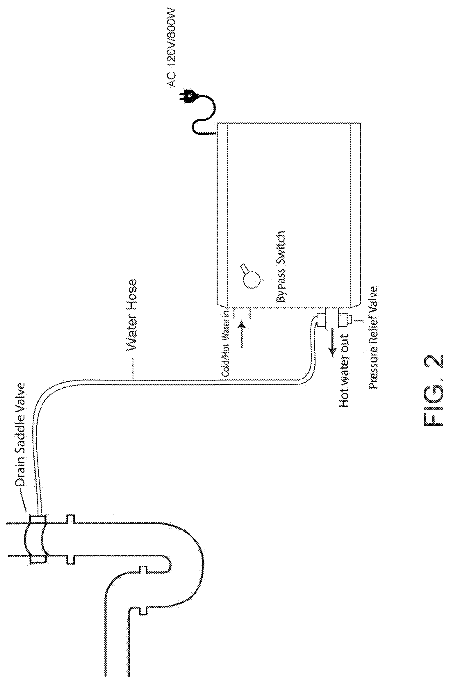
[0015] FIG. 2 is a perspective view of the hot water system in the preferred embodiment of the present invention, showing the electrical water heater is placing in horizontal position.
DETAILED DESCRIPTION OF THE INVENTION
[0016] The following description is disclosed to enable any person skilled in the art to make and use the present invention. Preferred embodiments are provided in the following description only as examples and modifications will be apparent to those skilled in the art. The general principles defined in the following description in the following description would be applied to other embodiments, alternatives, modifications, equivalents, and applications without departing from the spirit and scope of the present invention.
[0017] According to the preferred embodiment, the hot water system is a system comprises a 120V/800 W electrical water heater installed under a sink, a bypass switch on the water heater, a pressure relief valve on the outgoing water pipe of the water heater, a drain saddle valve installed on the drain pipe of the sink, and a water hose connecting both valves.
[0018] FIG. 1 is a perspective view of the hot water system in the preferred embodiment of the present invention. The preferred embodiment of the present invention of a hot water system further demonstrates that the 120V/800 W electrical water heater is installed under the sink in an upright standing position with a bypass switch on the upper right side, wherein a user is able to switch off the water heater when instant hot water is not in demand. A pressure relief is installed on the outgoing water pipe of the water heater working together with a drain saddle valve installed on the drain pipe of the sink to prevent water damage of water leaking. Both valves are connected with an extra water hose, in case water leak happens, the leaking water will be drained out from the pressure relief valve directly to drain pipe so water damage can be avoided.
[0019] FIG. 2 is a perspective view of the hot water system in the preferred embodiment of the present invention with the 120V/800 W electrical water heater installed in a horizontal position under a sink. The preferred embodiment of the present invention of a water system further demonstrates that the placement position of the 120V/800 W electrical water heater is interchangeable to fit the limited space under sinks. A bypass switch is used on the upper right side of the electrical water heater, wherein a user is able to switch off the water heater when instant hot water is not in demand. A pressure relief is installed on the outgoing water pipe of the water heater working together with a drain saddle valve installed on the drain pipe of the sink to prevent water damage of water leaking. Both valves are connected with an extra water hose, in case water leak happens, the leaking water will be drained out from the pressure relief valve directly to drain pipe so water damage can be avoided.
[0020] A hot water system can be used in an area around the sink, of which the instant hot water is often in need. The 120V/800 W electrical water heater can be affixed to any area under the sink with the incoming and the outgoing water pipe connected to the existing piping system of the sink. Once the faucet of hot water is turned on, cold water will be running from the existing pipe to the water heater through incoming water pipe and be instantly heated. Then the heated hot water will be running out of the water heater through the outgoing pipe of the water heater to the existing pipe to reach all the way to the faucet. This is how the instant hot water is achieved with the hot water system. Although the electrical water heater used in the present invention is a low voltage heater and may only able to supply instant heated water in a fairly short time, with the water running in existing piping system, the main water heater will be working at the same time to supply hot water all the way to where the faucet is turned on. That's why only a low voltage water heater is required in the hot water system, so extra energy consumption can be saved.
[0021] A main objective of the invention is to supply instant hot water to save the time that people are currently spending on waiting for hot water running from the main water heater. In a large two-story house, it could take a long time waiting for the hot water to reach the most distant faucet in the house. With the hot water system, not only the waiting time can be saved, the large amount of clean cold water going down directly to the drain pipe is saved as well. Furthermore, the total energy consumption will be lower with the present invention of hot water system applied.
[0022] One skilled in the art will understand that the embodiment of the present invention as shown in the drawings and described above is exemplary only and not intended to be limiting.
[0023] It will thus be seen that the objects of the present invention have been fully and effectively accomplished. The embodiments have been shown and described for the purposes of illustrating the functional and structural principles of the present invention and is subject to change without departure from such principles. Therefore, this invention includes all modifications encompassed within the spirit and scope of the following claims.
* * * * *
D00000
D00001
D00002
XML
uspto.report is an independent third-party trademark research tool that is not affiliated, endorsed, or sponsored by the United States Patent and Trademark Office (USPTO) or any other governmental organization. The information provided by uspto.report is based on publicly available data at the time of writing and is intended for informational purposes only.
While we strive to provide accurate and up-to-date information, we do not guarantee the accuracy, completeness, reliability, or suitability of the information displayed on this site. The use of this site is at your own risk. Any reliance you place on such information is therefore strictly at your own risk.
All official trademark data, including owner information, should be verified by visiting the official USPTO website at www.uspto.gov. This site is not intended to replace professional legal advice and should not be used as a substitute for consulting with a legal professional who is knowledgeable about trademark law.