Fuel Injector Fixation
Corbin; Chris ; et al.
U.S. patent application number 16/393989 was filed with the patent office on 2020-10-29 for fuel injector fixation. The applicant listed for this patent is BSH Hausgerate GmbH, BSH Home Appliances Corporation. Invention is credited to Chris Corbin, Daniel Davison, Timothy Russell, Brian Silva, Tyson White.
| Application Number | 20200340675 16/393989 |
| Document ID | / |
| Family ID | 1000004051671 |
| Filed Date | 2020-10-29 |


| United States Patent Application | 20200340675 |
| Kind Code | A1 |
| Corbin; Chris ; et al. | October 29, 2020 |
FUEL INJECTOR FIXATION
Abstract
Improvements for a gas burner bar are provided utilizing reduced parts, easier assembly, and greater reliability. In one or more implementations a portion of an air shutter is disposed between two parts of an injector assembly: an injector and an injector fitting. Assembly in this manner results in proper alignment of the injector assembly thus negating problems that arise with misalignment.
| Inventors: | Corbin; Chris; (LaFollette, TN) ; Davison; Daniel; (Knoxville, TN) ; Russell; Timothy; (Jacksboro, TN) ; Silva; Brian; (Knoxville, TN) ; White; Tyson; (Anderson, TN) | ||||||||||
| Applicant: |
|
||||||||||
|---|---|---|---|---|---|---|---|---|---|---|---|
| Family ID: | 1000004051671 | ||||||||||
| Appl. No.: | 16/393989 | ||||||||||
| Filed: | April 25, 2019 |
| Current U.S. Class: | 1/1 |
| Current CPC Class: | F24C 3/087 20130101 |
| International Class: | F24C 3/08 20060101 F24C003/08 |
Claims
1. A gas burner bar, comprising: a burner; a Venturi tube attached to the burner; an air shutter attached to the Venturi tube, the air shutter having an opening; an injector, the injector situated through the opening of the air shutter; and an injector fitting, the injector fitting attached to the injector.
2. The burner bar of claim 1, wherein the burner has a burner region with a plurality of combustion points.
3. The burner bar of claim 1, wherein the air shutter has a secondary opening for the entry of air into the gas burner bar.
4. The burner bar of claim 1, wherein a portion of the air shutter is disposed between the injector fitting and the injector.
5. The burner bar of claim 4, wherein the air shutter has a threadless, raised opening.
6. The burner bar of claim 4, wherein the injector is flush against the portion of the air shutter.
7. The burner bar of claim 4, wherein the injector has an opening that is collinear with the Venturi tube.
8. The burner bar of claim 3, further comprising: a gas line attached to the injector fitting to provide a fuel gas; and a regulator attached to the gas line to regulate flow of the fuel gas.
9. The burner bar of claim 8, wherein the fuel gas enters a mixing face of the air shutter through the nozzle, mixes with air from the secondary opening of the air shutter, passes through the Venturi tube as an air/gas mixture, and combusts at the burner.
10. A cooking appliance, the cooking appliance comprising: a cooking cavity; and a gas burner bar disposed in the cooking cavity, the gas burner bar comprising: a burner, a Venturi tube attached to the burner, an air shutter attached to the Venturi tube, the air shutter having an opening; an injector, the injector situated through the opening of the air shutter; and an injector fitting, the injector fitting attached to the injector.
11. The cooking appliance of claim 10, wherein the gas burner bar is operated as a bake burner.
12. The cooking appliance of claim 10, wherein the gas burner bar is operated as a broil burner.
13. The cooking appliance of claim 10, wherein the air shutter has a secondary opening for the entry of air into the gas burner bar.
14. The cooking appliance of claim 10, wherein a portion of the air shutter is disposed between the injector fitting and the injector.
15. The cooking appliance of claim 15, wherein the injector has an opening that is collinear with the Venturi tube.
16. The cooking appliance of claim 13, the gas burner bar further comprising: a gas line attached to the injector fitting to provide a fuel gas; and a regulator attached to the gas line to regulate flow of the fuel gas.
17. The burner bar of claim 13, wherein the fuel gas enters a mixing face of the air shutter through the nozzle, mixes with air from the secondary opening of the air shutter, passes through the Venturi tube as an air/gas mixture, and combusts at the burner.
18. A mixing unit for a gas burner, the mixing unit comprising: an injector fitting; an air shutter disposed against the injector fitting; and an injector disposed in the air shutter opposite the injector fitting and engaged with the injector fitting through an opening in the air shutter.
19. The mixing unit for the gas burner of claim 18, further comprising: a Venturi tube attached to the air shutter and disposed both opposite from and collinear to the injector.
Description
FIELD OF TECHNOLOGY
[0001] The present technology relates to improvements in gas burners.
BACKGROUND
[0002] Gas burner assemblies are used in traditional gas cooking ranges in both broiler and baking configurations. Traditionally these gas burner assemblies are comprised of several components, including a gas burner, a Venturi tube, an air shutter, an injector fitting and an injector.
[0003] Traditionally the injector is secured to the injector fitting and the injector fitting is secured to the air shutter. However, this solution does not ensure the alignment of the injector to the Venturi tube and misaligns the orifice of the injector in mixing face. Alternative solutions utilize a floating injector that sits in the air shutter, however this solution provides no fixation or consistency in results.
[0004] These traditional methods of assembly are problematic because misalignment of the injector can result in malfunction of the gas burner assembly which can manifest in the creation of soot, flashback, and flame lifting. Furthermore these traditional methods of assembly use several components, any variation of which or misassembly of can result in misalignment.
[0005] Accordingly, what is needed is a way to reliably and repeatedly ensure proper alignment of the injector and the injector fitting when fixing the combination to the air shutter of a gas burner.
BRIEF SUMMARY
[0006] The present invention is directed to improvements in gas burners. These improvements include reduced part counts in injector assemblies, increased reliability, easier assembly, and a reduction in misaligned gas burner problems.
[0007] The invention is an improved injector assembly that is constructed out of two components: an injector fitting and an injector. During assembly the injector is passed through the opening of the air shutter and threaded into the injector fitting. As a result, the air shutter is sandwiched between the injector and the injector fitting, resulting in a flush placement of the injector against either the wall or raised opening of the air shutter. Furthermore this method of engagement holds the air shutter and the injector assembly in proper position with fewer chances of erroneous placement.
[0008] These improvements to the injector assembly allow for an improved gas burner that uses fewer parts, is easier to assemble, has increased reliability, and a marked reduction in problems that arise from a misaligned injector including, but not limited to, flashback, flame lifting, and increased soot.
[0009] Various other objects, features, aspects, and advantages of the present invention will become more apparent to those skilled in the art upon review of the following detailed description of preferred embodiments of the invention and accompanying drawings in which like numerals represent like components.
BRIEF DESCRIPTION OF THE DRAWINGS
[0010] FIG. 1 is a perspective view of a gas burner bar in accordance with embodiments of the invention.
[0011] FIG. 2 is a perspective view of the unassembled injector assembly.
[0012] FIG. 3 is a perspective, exploded view of the unassembled injector assembly portion of the gas burner bar.
[0013] FIG. 4 is a perspective, angled view of the assembled injector assembly portion of the gas burner bar.
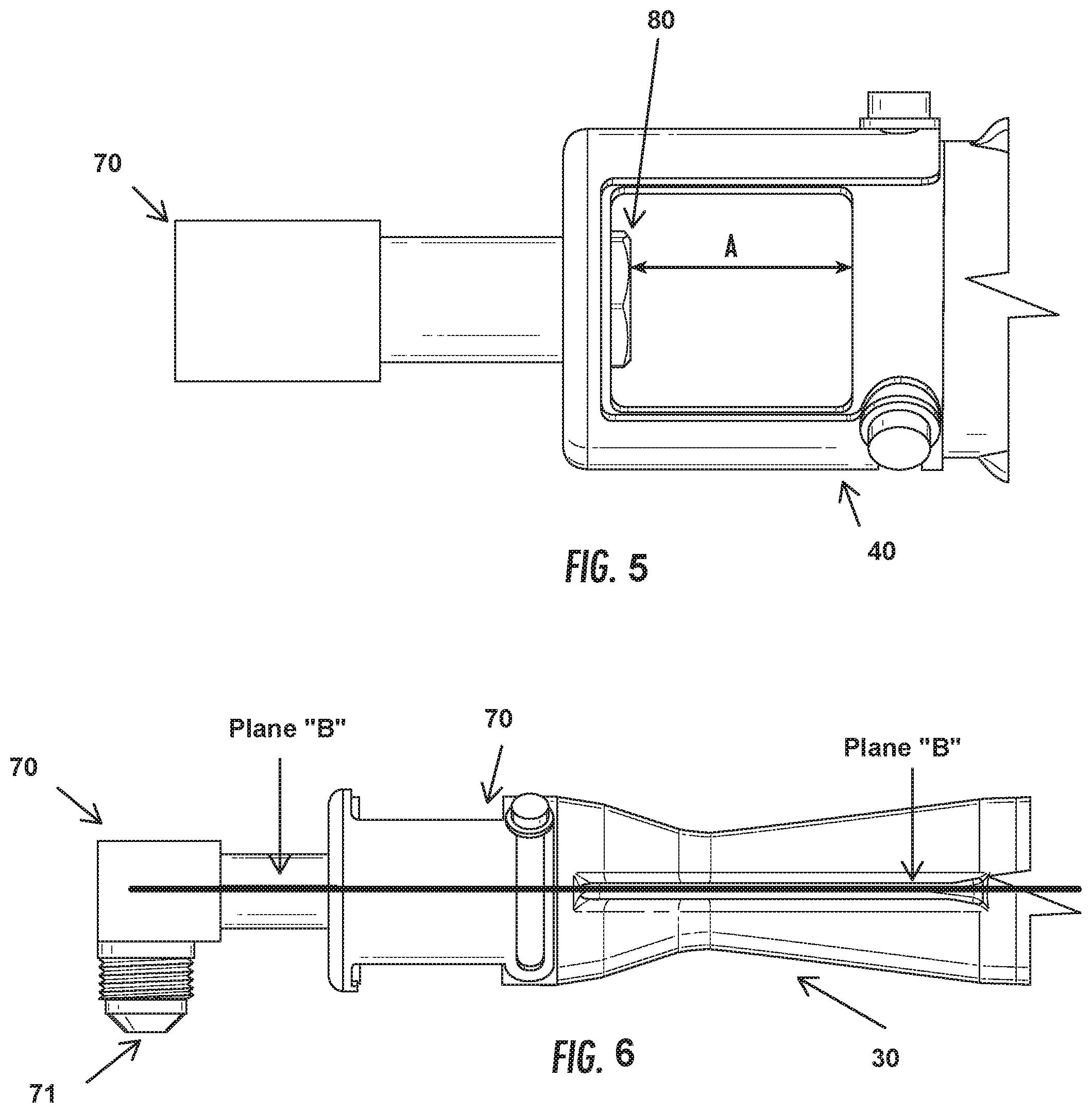
[0014] FIG. 5 is a perspective, side view of the assembled injector assembly portion of the gas burner bar.
[0015] FIG. 6 is a perspective, alternative side view of the assembled injector assembly portion of the gas burner bar.
DETAILED DESCRIPTION
[0016] The present invention now is described more fully hereinafter with reference to the accompanying drawings, in which embodiments of the invention are shown. This invention may, however, be embodied in many different forms and should not be construed as limited to the embodiments set forth herein; rather, these embodiments are provided so that this disclosure will be thorough and complete, and will fully convey the scope of the invention to those skilled in the art.
[0017] Throughout this disclosure, the terms top, bottom, front, back, left and right may be used. These terms are only intended to provide relational orientation with respect to one another. For example, any two opposed sides can be a right side and a left side and by changing to an opposed viewpoint, right versus left will be changed. Thus, top, bottom, front, back, left and right should not be considered limiting and are used only to distinguish their relationship to one another.
[0018] A major component of combustion systems is the mixer which mixes fuel gas with combustion air and sends the mixture to the burner at a fixed pressure. Important to the mixing process is the location and alignment of the gas orifice in relation to both the air intake and the Venturi tube. A misaligned or mislocated gas orifice can result in several forms of burner malfunction such as the creation of or increased amount of soot, flashback, and/or flame lifting at the burner.
[0019] FIG. 1 illustrates a standard burner bar in a gas oven utilizing the improved injector assembly of the present invention. The gas burner bar (10) generally includes a burner region (20), a Venturi tube (30), an air shutter (40), and an improved injector assembly (50). While the burner bar is depicted as having an L-bend region (60), alternative embodiments allow for a burner bar without a band (e.g., straight). Generally, fuel gas is injected into the burner bar via the injector assembly; combustion air is drawn into the burner bar at the air shutter due to reduced pressure at the Venturi tube, allowing the combustion air to begin mixing with the fuel gas; the combustion air and fuel gas mixture is drawn into and through the Venturi tube and is taken to the burner region where combustion occurs at a plurality of combustion points.
[0020] FIG. 2 illustrates a perspective view of the injector assembly in accordance with embodiments of the invention in an unassembled state, and FIG. 3 illustrates an exploded, close-up view of the unassembled improved injector assembly in conjunction with the air shutter and Venturi tube. The injector assembly (50) is assembled out of two components: an injector fitting (70) and an injector (80). The injector fitting has two attachment points (71 & 72). The first attachment point (71) is positioned distal to the air shutter (40) and is generally connected to a gas line (not shown) which provides a fuel gas to the burner bar (10). To facilitate the connection to the gas line, the first attachment has male threads, although alternative methods of connection can be utilized.
[0021] The second attachment point (72) of the injector fitting is positioned proximal to the air shutter and, in contrast to the first attachment point, has female threads. This is an improvement over previous solutions for injector fittings, which will be illustrated shortly.
[0022] The injector (80) has an orifice (81) through which gas passes through the injector into the air shutter (40) and the Venturi tube (30). In a preferred embodiment, the injector has a hexagonal head for ease of assembly, but alternative shapes can be utilized (e.g., square). This gas flow is controlled by a regulator (not shown) connected to the gas line, the gas line being connected to the first attachment point of the injector fitting. The injector has male threads that are inserted into the female threads of the second attachment point of the injector fitting.
[0023] Sandwiched between the injector and the injector fitting is a portion of the air shutter. As illustrated in FIG. 3, the air shutter has a threadless, raised opening (41) through which the injector (80) passes through. After passing through the opening, the injector is then threaded into the second attachment point of the injector fitting. As a result, when engaged the injector and the injector fitting secure the air shutter in a sandwich manner. Furthermore, this arrangement also serves to hold the injector fitting and injector in proper alignment. In alternative embodiments there is no raised section of the opening (41) in the air shutter.
[0024] FIGS. 4, 5 and 6 illustrate close-up, perspective views of the assembled injector assembly and air shutter. As shown in FIGS. 4 and 5, when the injector (80) is secured to the injector fitting (70) the head of the injector is held flush against the air shutter (40). As shown in FIG. 4, when secured according to the preferred embodiment of this invention, the head of the injector is properly positioned in the mixing face, labeled as dimension "A." This proper positioning results in a proper air fuel mixture entering the Venturi tube (30). Additionally, by securing the injector to the air shutter by sandwiching the air shutter between the injector and the injector fitting, this proper positioning of the injector is repeatable during assembly of the gas burner bar (10). Notably, by securing the injector internally, the proper direction is established in an internal fashion rather than in an external fashion.
[0025] As shown in FIG. 6, when secured according to the preferred embodiment of this invention, the center line of the injector fitting (70), the injector (80), and the Venturi tube (30) are collinear (labeled as plane "B"), contributing to consistent gas flow and mixing while reducing flashback, flame lifting, and soot created as a result of misaligned injectors.
[0026] The present invention can be disposed in any gas cooking appliance that utilizes a gas burner bar, in particular cooking appliances with broil and/or bake functionality in an oven cavity used for the heating of foodstuffs.
[0027] The present invention has been described herein in terms of several preferred embodiments. However, modifications and additions to these embodiments will become apparent to those of ordinary skill in the art upon a reading of the foregoing description. It is intended that all such modifications and additions comprise a part of the present invention to the extent that they fall within the scope of the several claims appended hereto.
* * * * *
D00000
D00001
D00002
D00003
D00004
XML
uspto.report is an independent third-party trademark research tool that is not affiliated, endorsed, or sponsored by the United States Patent and Trademark Office (USPTO) or any other governmental organization. The information provided by uspto.report is based on publicly available data at the time of writing and is intended for informational purposes only.
While we strive to provide accurate and up-to-date information, we do not guarantee the accuracy, completeness, reliability, or suitability of the information displayed on this site. The use of this site is at your own risk. Any reliance you place on such information is therefore strictly at your own risk.
All official trademark data, including owner information, should be verified by visiting the official USPTO website at www.uspto.gov. This site is not intended to replace professional legal advice and should not be used as a substitute for consulting with a legal professional who is knowledgeable about trademark law.