Permanent Magnet Pump With Bearings Separating Modular Sections
Martinez; Ignacio ; et al.
U.S. patent application number 16/856714 was filed with the patent office on 2020-10-29 for permanent magnet pump with bearings separating modular sections. This patent application is currently assigned to Baker Hughes Oilfield Operations LLC. The applicant listed for this patent is Baker Hughes Oilfield Operations LLC. Invention is credited to Shawn Gunter, Yong Li, Ignacio Martinez, Ameen Muhammed, Risa Rutter, Gary Williams, Zheng Ye.
| Application Number | 20200340481 16/856714 |
| Document ID | / |
| Family ID | 1000004827334 |
| Filed Date | 2020-10-29 |


| United States Patent Application | 20200340481 |
| Kind Code | A1 |
| Martinez; Ignacio ; et al. | October 29, 2020 |
PERMANENT MAGNET PUMP WITH BEARINGS SEPARATING MODULAR SECTIONS
Abstract
A well fluid pump has a housing with a stator having a stack of discs through which windings extend. First and second stage modules in a bore of the stator have rotating impellers and non-rotating diffusers. Magnets mounted in each of the stage modules rotate the impellers in response to electromagnetic fields generated by the windings. Anti-rotation members join adjacent ones of the impellers together in each of the stage modules for rotation in unison. A bearing assembly between the first and second stage modules has a rotatable inner portion in engagement with the impellers in the first and second stage modules for causing them to rotate in unison. The bearing assembly has a non-rotating outer portion in engagement with the stator to prevent rotation.
| Inventors: | Martinez; Ignacio; (Tulsa, OK) ; Williams; Gary; (Tulsa, OK) ; Muhammed; Ameen; (Claremore, OK) ; Ye; Zheng; (Claremore, OK) ; Rutter; Risa; (Claremore, OK) ; Li; Yong; (Claremore, OK) ; Gunter; Shawn; (Tulsa, OK) | ||||||||||
| Applicant: |
|
||||||||||
|---|---|---|---|---|---|---|---|---|---|---|---|
| Assignee: | Baker Hughes Oilfield Operations
LLC HOUSTON TX |
||||||||||
| Family ID: | 1000004827334 | ||||||||||
| Appl. No.: | 16/856714 | ||||||||||
| Filed: | April 23, 2020 |
Related U.S. Patent Documents
| Application Number | Filing Date | Patent Number | ||
|---|---|---|---|---|
| 62837917 | Apr 24, 2019 | |||
| 62837944 | Apr 24, 2019 | |||
| 62837961 | Apr 24, 2019 | |||
| Current U.S. Class: | 1/1 |
| Current CPC Class: | F04D 29/046 20130101; F04D 13/086 20130101; E21B 43/128 20130101; F04D 29/448 20130101; F04D 1/06 20130101 |
| International Class: | F04D 13/08 20060101 F04D013/08; F04D 29/046 20060101 F04D029/046; F04D 29/44 20060101 F04D029/44; F04D 1/06 20060101 F04D001/06; E21B 43/12 20060101 E21B043/12 |
Claims
1. An apparatus for pumping fluid, comprising: a housing having a longitudinal axis; a stator mounted for non-rotation in the housing, the stator having a stack of discs through which windings extend, the stator having a central bore extending along the axis; first and second stage modules in the central bore, each of the stage modules having a plurality of impellers and diffusers, the diffusers being mounted within each stage module for non-rotation; a set of magnets mounted in each of the stage modules for rotating the impellers in response to electromagnetic fields generated by the windings; anti-rotation members in each of the first and second modules joining adjacent ones of the impellers in each of the stage modules together for rotation in unison; a bearing assembly between the first and second stage modules; the bearing assembly having a rotatable inner portion in engagement with the impellers in the first stage module and in engagement with the impellers in the second stage module for causing the impellers in the first stage module to rotate in unison with the impellers in the second stage module; and the bearing assembly having a non-rotating outer portion in engagement with a sidewall of the bore of the stator to prevent rotation of the outer portion, the inner portion of the bearing assembly being in rotating sliding engagement with the outer portion of the bearing assembly.
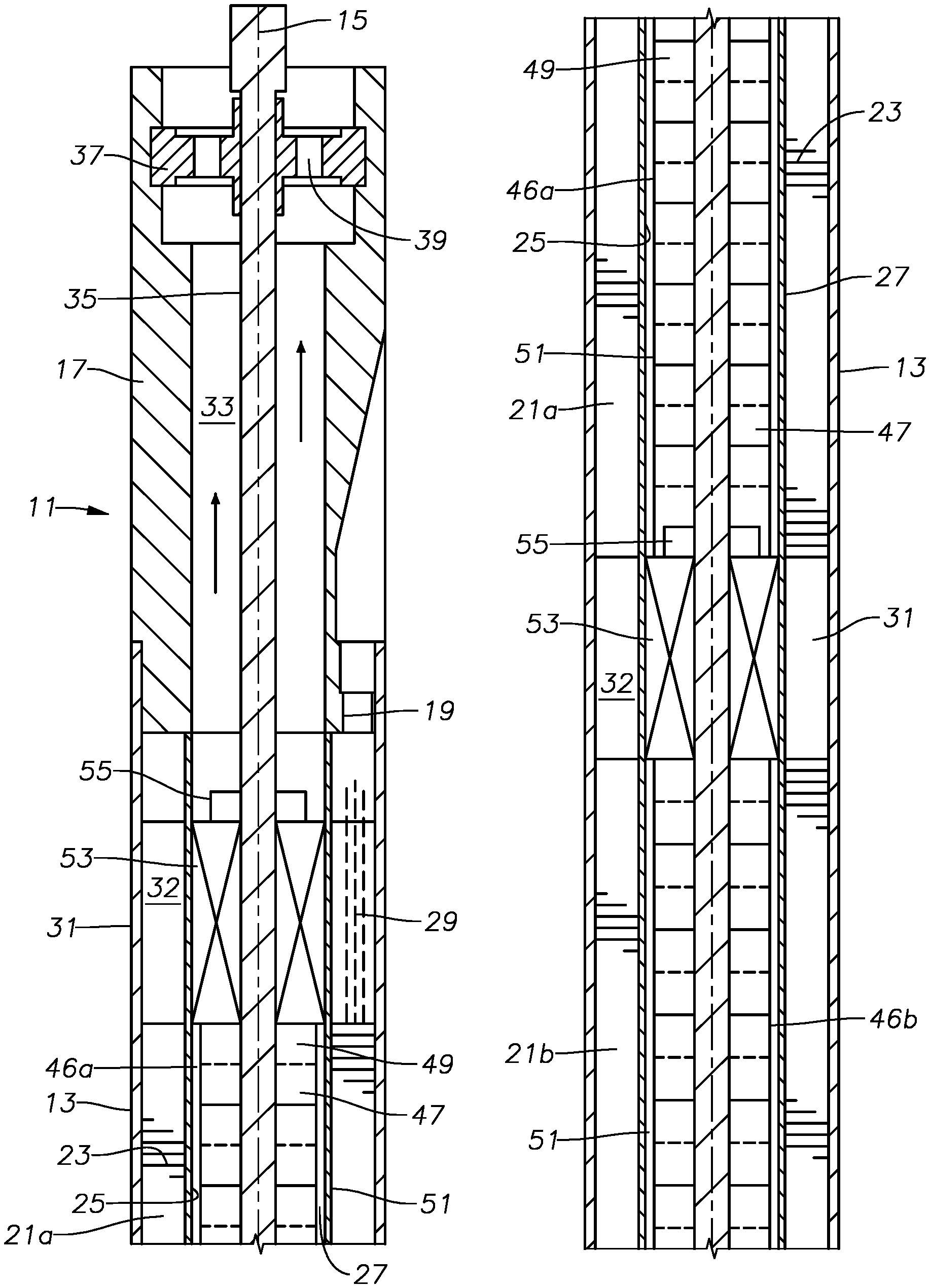
2. The apparatus according to claim 1, further comprising: a down thrust pad between the inner and outer portions of the bearing assembly for transferring down thrust from the inner portion to the outer portion.
3. The apparatus according to claim 2, further comprising: an up thrust pad between the inner and outer portions of the bearing assembly for transferring up thrust from the inner portion to the outer portion.
4. The apparatus according to claim 1, further comprising: a plurality of impeller sleeves, each of the impeller sleeves extending from one end to another end of one of the stage modules, each of the sleeves surrounding and rotating in unison with the impellers within one of the stage modules; and fasteners that secure the impeller sleeves of the first and second stage modules to the inner portion of the bearing assembly.
5. The apparatus according to claim 1, wherein: the anti-rotation members within the first and second stage modules comprise a tab and recess arrangement between adjacent ones of the impellers.
6. The apparatus according to claim 1, wherein: the stator has a first section surrounding the first stage module and a second section surrounding the second stage module; the stator further comprising: a bearing locator sandwiched between the first and second sections of the stator, the bearing locator having an inward facing sidewall surrounding the axis and the bearing assembly; a slot formed in the inward facing sidewall; and a key on the outer portion of the bearing assembly that engages the slot to prevent rotation of the outer portion of the bearing assembly.
7. The apparatus according to claim 6, wherein the bearing assembly is free to move axially a limited extent relative to the bearing locator.
8. The apparatus according to claim 6, further comprising: windings passages in the bearing locator; and wherein the windings passing through the first and second sections of the stator pass through the windings passages.
9. The apparatus according to claim 1, wherein: the inner portion of the bearing assembly has a central passage for flowing well fluid from the second stage module to the first stage module.
10. The apparatus according to claim 9, further comprising: a torque sleeve extending between a lowest impeller in the first stage module and the inner portion of the bearing assembly to cause the inner portion of the bearing assembly to rotate with the impellers of the first stage module.
11. The apparatus according to claim 1, further comprising: a shaft mounted on the axis for non-rotation relative to the housing; wherein each of the impellers has a hub through which the shaft extends, allowing rotating of the impellers and allowing limited axial movement of the impellers relative to the shaft; and a key and slot arrangement between the diffusers and the shaft that prevents rotation of the diffusers relative to the shaft, but allows limited axial movement of the diffusers relative to the shaft.
12. The apparatus according to claim 1, further comprising: a shaft mounted on the axis for non-rotation relative to the housing; wherein at least some of the diffusers in each of the modules comprise inter-stage diffusers that are axially movable a limited extent on the shaft; each of the inter-stage diffusers is configured for receiving down thrust from an adjacent upper one of the impellers; and each of the inter-stage diffusers is configured to transfer the down thrust received to an adjacent lower one of the impellers.
13. The apparatus according to claim 1, further comprising: a shaft mounted on the axis for non-rotation relative to the housing; wherein the diffusers within each of the modules comprise inter-stage diffusers located above an axially fixed diffuser at a lower end of each of the modules; each of the inter-stage diffusers within each of the modules is free to slide axially on the shaft a limited extent; the axially fixed diffuser in each of the modules is axially and rotationally fixed to the shaft; and wherein the apparatus further comprises an inter-stage thrust pad on an upper side of each of the inter-stage diffusers for receiving down thrust from an adjacent upper one of the impellers and transferring the down thrust to an adjacent lower one of the impellers; and an axially fixed diffuser thrust pad on an upper side of the axially fixed diffuser in each of the modules for receiving down thrust from an adjacent upper one of the impellers.
14. The apparatus according to claim 1, wherein each of the impellers comprises: impeller vanes with a vane intake on an lower side of the impeller vanes and a vane outlet on an upper side of the impeller vanes; a coaxial, cylindrical wall defining a periphery of each of the impellers, the cylindrical wall having an upper portion extending upward from the upper side of the impeller vanes, the cylindrical wall having an upper rim; wherein each of the diffusers is carried within and surrounded by the upper portion of one of the cylindrical walls; and the anti-rotation members that rotationally locks each of the impellers to adjacent ones of the impellers is a tab and slot arrangement on the rim and on a lower end of the cylindrical wall of each of the impellers.
15. The apparatus according to claim 1, further comprising: a capsule having a bulkhead at one end, the housing being carried within the capsule; the housing having an intake member on one end and a discharge member on an opposite end; one of the discharge and intake members being secured to an inner side of the bulkhead; and a port extending through the bulkhead in registry with either the discharge member or the intake member for the flow of well fluid.
16. The apparatus according to claim 15, wherein: the port extends along the axis of the housing.
17. An apparatus for pumping fluid, comprising: a housing having a longitudinal axis; a stator mounted for non-rotation in the housing, the stator having a stack of discs through which windings extend, the stator having a central bore extending along the axis; a shaft mounted on the axis for non-rotation relative to the housing; a plurality of impellers, each having a hub through which the shaft extends; an impeller bearing in the hub of each of the impellers, facilitating rotation of each of the impellers relative to the shaft; each of the impellers being free to move axially on the shaft a limited extent; a set of magnets on each of the impellers for rotating the impellers in response to electromagnetic fields generated by the windings; a plurality of inter-stage diffusers, each mounted between adjacent one of the impellers; a key and slot arrangement between each of the inter-stage diffusers and the shaft for preventing rotation of each of the diffusers but allowing limited axial movement on the shaft; and an axially fixed diffuser at the lower end of the inter-stage diffusers, the axially fixed diffuser being non-rotatable and axially fixed to the shaft.
18. The apparatus according to claim 17, wherein: the impellers are configured to transfer down thrust to an adjacent lower one of the inter-stage diffusers; and the inter-stage diffusers are configured to transfer the down thrust received to a next lower one of the impellers; and the axially fixed diffuser is configured to receive and transfer the down thrust received to the shaft.
19. An apparatus for pumping fluid, comprising: a housing having a longitudinal axis; a stator mounted for non-rotation in the housing, the stator having a stack of discs through which windings extend, the stator having a central bore extending along the axis; a shaft mounted on the axis for non-rotation relative to the housing; a plurality of impellers, each having a hub through which the shaft extends; each of the impellers being free to rotate on the shaft and move axially on the shaft a limited extent; a set of magnets on each of the impellers for rotating the impellers in response to electromagnetic fields generated by the windings; wherein each of the impellers comprises: impeller vanes with a vane intake on an lower side of the impeller vanes and a vane outlet on an upper side of the impeller vanes; a coaxial, cylindrical wall defining a periphery of each of the impellers, the cylindrical wall having an upper portion extending upward from the upper side of the impeller vanes, the cylindrical wall having an upper rim; a diffuser carried within and surrounded by the upper portion of each of the cylindrical walls; and a tab and slot arrangement on the rim and a lower end of the cylindrical wall of each of the impellers that rotationally locks each of the impellers to adjacent ones of the impellers.
20. The apparatus according to claim 19, wherein: the diffusers are secured to the shaft for non-rotation and have smaller outer diameters than the impellers.
Description
CROSS REFERENCE TO RELATED APPLICATIONS
[0001] This application claims priority to provisional application 62/837,917, filed Apr. 24, 2019, provisional application 62/837,944, filed Apr. 24, 2019, and provisional application 62/837,961, filed Apr. 24, 2019.
FIELD OF DISCLOSURE
[0002] The present disclosure relates to a centrifugal pump with magnets mounted to the impellers that cause the impellers to rotate in response to electromagnetic fields emanating from a stator. More specifically, the impellers are in stage modules and rotate in unison, the modules being separated from each other by a bearing that causes the impellers in one module to rotate in unison with the impellers in the adjacent module.
BACKGROUND
[0003] Electrical submersible pumps (ESP) are commonly used in hydrocarbon producing wells. A typical ESP includes an electrical motor having a rotating drive shaft that drives the pump. The pump is often a centrifugal pump having a large number of stages. Each stage has a nonrotating diffuser and a rotating impeller. The motor has a drive shaft that couples to the pump shaft to rotate the impellers. The motor may have lengths up to 30 feet or more. Radial motor bearings support the motor shaft along the length. A dielectric fluid in the motor lubricates the motor bearings. A pressure equalizer mounts to the motor to reduce a pressure difference between the dielectric lubricant in the motor and the well fluid on the exterior. A shaft seal, usually at an end of the pressure equalizer, seals around the drive shaft to prevent the entry of well fluids into the motor lubricant.
[0004] In some cases, pumps are mounted in tandem and motors are mounted in tandem, creating a lengthy assembly. A workover rig is often required to install and retrieve the assembly. The motor relies on well fluid flowing past to cool the motor. Consequently, some arrangements must be made to achieve well fluid flow. For example, the motor may be positioned above the casing perforations or a shroud surrounding the motor may be deployed. Alternately, a small tube may extend alongside the motor from the pump to below the motor to divert a portion of the well fluid being pumped by the pump.
[0005] While very successful, ESP's have many parts, adding cost and reliability issues. The shaft seal creates a leakage path for well fluid, which can cause motor failure. The long length can create problems in installing the pump within curved sections of a deviated well.
[0006] There are known designs to combine the motor and pump into a single unit. In these designs, a stator with motor windings surrounds the impellers and diffusers. The impellers have permanent magnets mounted to them that rotate in response to the electromagnetic fields generated by the stator windings.
SUMMARY
[0007] An apparatus for pumping fluid includes a housing having a longitudinal axis. A stator mounted for non-rotation in the housing has a stack of discs through which windings extend. The stator has a central bore extending along the axis. First and second stage modules are in the central bore. Each of the stage modules has a plurality of impellers and diffusers. The diffusers are mounted within each stage module for non-rotation. A set of magnets mounted in each of the stage modules rotates the impellers in response to electromagnetic fields generated by the windings. Anti-rotation members in each of the first and second modules join adjacent ones of the impellers in each of the stage modules together for rotation in unison.
[0008] A bearing assembly between the first and second stage modules has a rotatable inner portion in engagement with the impellers in the first stage module and in engagement with the impellers in the second stage module for causing the impellers in the first stage module to rotate in unison with the impellers in the second stage module. The bearing assembly has a non-rotating outer portion in engagement with a sidewall of the bore of the stator to prevent rotation of the outer portion. The inner portion of the bearing assembly is in rotating sliding engagement with the outer portion of the bearing assembly.
[0009] A down thrust pad may be between the inner and outer portions of the bearing assembly for transferring down thrust from the inner portion to the outer portion. An up thrust pad may be between the inner and outer portions of the bearing assembly for transferring up thrust from the inner portion to the outer portion.
[0010] In the embodiment shown, there are a plurality of impeller sleeves. Each of the impeller sleeves extends from one end to another end of one of the stage modules. Each of the sleeves surrounds and rotates in unison with the impellers within one of the stage modules. Fasteners secure the impeller sleeves of the first and second stage modules to the inner portion of the bearing.
[0011] In one embodiment, the anti-rotation members within the first and second stage modules comprise a tab and recess arrangement between adjacent ones of the impellers.
[0012] The stator has a first section surrounding the first stage module and a second section surrounding the second stage module. The stator may have a bearing locator sandwiched between the first and second sections of the stator. The bearing locator has an inward facing sidewall surrounding the axis and the bearing assembly. In this example, a slot formed in the inward facing sidewall receives a key on the outer portion of the bearing assembly to prevent rotation of the outer portion of the bearing assembly. The bearing assembly may be free to move axially a limited extent relative to the bearing locator. The bearing locator may have windings passages. The windings that pass through the first and second sections of the stator also pass through the windings passages.
[0013] The inner portion of the bearing assembly has a central passage for flowing well fluid from the second stage module to the first stage module. In one embodiment, an annular space between the inner and outer portions of the bearing assembly defines a flow path from the central passage for providing lubrication between the inner and outer portions of the bearing assembly.
[0014] In one embodiment, a shaft is mounted on the axis for non-rotation relative to the housing. Each of the impellers has a hub through which the shaft extends, allowing rotating of the impellers and allowing limited axial movement of the impellers relative to the shaft. A key and slot arrangement between the diffusers and the shaft prevents rotation of the diffusers relative to the shaft, but allows limited axial movement of the diffusers relative to the shaft. More particularly, at least some of the diffusers in each of the modules comprise inter-stage diffusers that are axially movable a limited extent on the shaft. Each of the inter-stage diffusers is configured for receiving down thrust from an adjacent upper one of the impellers. Each of the inter-stage diffusers is configured to transfer the down thrust received to an adjacent lower one of the impellers.
[0015] An axially fixed diffuser is at a lower end of each of the modules in one example. The axially fixed diffuser in each of the modules is axially and rotationally fixed to the shaft. An inter-stage thrust pad may be on an upper side of each of the inter-stage diffusers for receiving down thrust from an adjacent upper one of the impellers and transferring the down thrust to an adjacent lower one of the impellers. An axially fixed diffuser thrust pad may be on an upper side of the axially fixed diffuser in each of the modules for receiving down thrust from an adjacent upper one of the impellers.
[0016] In the embodiment shown, impeller vanes have a vane intake on a lower side of the impeller vanes and a vane outlet on an upper side of the impeller vanes. A coaxial, cylindrical wall defines a periphery of each of the impellers. The cylindrical wall has an upper portion extending upward from the upper side of the impeller vanes and an upper rim. Each of the diffusers is carried within and surrounded by the upper portion of one of the cylindrical walls. The anti-rotation members that rotationally lock each of the impellers to adjacent ones of the impellers may comprise a tab and slot arrangement on the rim and on a lower end of the cylindrical wall of each of the impellers.
[0017] In one embodiment, the housing is carried within a capsule having a bulkhead at one end. The housing has an intake member on one end and a discharge member on an opposite end. One of the discharge and intake members is secured to an inner side of the bulkhead. A port extends through the bulkhead in registry with either the discharge member or the intake member for the flow of well fluid. The port extends along the axis of the housing.
BRIEF DESCRIPTION OF THE DRAWINGS
[0018] FIGS. 1A-1C comprise a sectional view of portions of a permanent magnet pump in accordance with this disclosure.
[0019] FIG. 2 is a sectional view of the upper anchor for a non-rotating shaft of the pump of FIGS. 1A-1C.
[0020] FIG. 3 is a sectional view of the shaft upper anchor, taken along the line 3-3 of FIG. 2.
[0021] FIG. 4 is a sectional view of part of the impeller and diffuser stages of the pump.
[0022] FIG. 5 is a perspective view from an upper side of one of the impellers.
[0023] FIG. 6 is a perspective view from a lower side of the impeller of FIG. 5.
[0024] FIG. 7 is a perspective view from an upper side of one of the inter-stage diffusers.
[0025] FIG. 8 is a perspective view from a lower side of an axially and rotationally locked diffuser at the lower end of one of the stage modules of the pump.
[0026] FIG. 9 is a sectional view of the intermediate bearing assembly between the two stage modules.
[0027] FIG. 10 is a sectional view of a rotating or inner portion of the bearing assembly of FIG. 9.
[0028] FIG. 11 is a sectional view of an outer or non-rotating portion of the bearing assembly of FIG. 9.
[0029] FIG. 12 is a schematic view of a first embodiment illustrating the pump of FIG. 1 mounted in a subsea capsule.
[0030] FIG. 13 is a schematic view of a second embodiment illustrating another pump mounted in a subsea capsule.
[0031] FIG. 14 is a schematic view of a third embodiment illustrating still another pump mounted in a subsea capsule.
[0032] While the disclosure will be described in connection with the preferred embodiments, it will be understood that it is not intended to limit the disclosure to that embodiment. On the contrary, it is intended to cover all alternatives, modifications, and equivalents, as may be included within the scope of the disclosure as defined by the appended claims.
DETAILED DESCRIPTION
[0033] The method and system of the present disclosure will now be described more fully hereinafter with reference to the accompanying drawings in which embodiments are shown. The method and system of the present disclosure may be in many different forms and should not be construed as limited to the illustrated embodiments set forth herein; rather, these embodiments are provided so that this disclosure will be thorough and complete, and will fully convey its scope to those skilled in the art. Like numbers refer to like elements throughout. In an embodiment, usage of the term "about" includes +/-5% of the cited magnitude. In an embodiment, usage of the term "substantially" includes +/-5% of the cited magnitude.
[0034] It is to be further understood that the scope of the present disclosure is not limited to the exact details of construction, operation, exact materials, or embodiments shown and described, as modifications and equivalents will be apparent to one skilled in the art. In the drawings and specification, there have been disclosed illustrative embodiments and, although specific terms are employed, they are used in a generic and descriptive sense only and not for the purpose of limitation.
[0035] Referring to FIGS. 1A-1C, pump 11 has a tubular housing 13, which has a longitudinal axis 15. A discharge head or member 17 secures to one end of housing 13 and may be considered to be a part of housing 13. Discharge member 17 has power cable receptacle features 19 for receiving a power cable and plug (not shown) to supply electrical power to pump 11.
[0036] Pump 11 has a stator 21 mounted in housing 13 for non-rotation relative to housing 13. Stator 21 has a stack of thin, metal discs or laminations 23 (only a few illustrated) that have central openings to define a central bore 25 coaxial with axis 15. A stator can or sleeve 27 of non-magnetic material encloses the inner diameters of discs 23. Windings 29, shown schematically, extend through axially aligned slots spaced circumferentially around central bore 25.
[0037] In this example, stator 21 has multiple sections, illustrated as an upper section 21a and a lower section 21b. The terms "upper", "lower" and the like are used only for convenience as pump 11 may be operated in more than vertical orientations, such as horizontal and inclined. An intermediate bearing locator 31 separates the two stator sections 21a, 21b. More than two stator sections 21a, 21b could be employed by having a longer housing 13 and more intermediate bearing locators 31. Each stator section 21a, 21b has a separate stator can 27.
[0038] Also, an upper bearing locator 31 may be located directly above stator upper section 21a and a lower bearing locator 31 directly below stator lower section 21b. Intermediate, upper and lower bearing locators 31 may be identical. Each bearing locator 31 is a tubular member having a central bore and axially extending slots 32 spaced circumferentially around the bore. Windings 29 extend through slots 32 as the windings pass continuously from the top of upper section 21a to the bottom of lower section 21b. Each bearing locator 31 may be of a non-ferrous material so as to avoid influencing magnetic fields emanating from stator 21.
[0039] Discharge member 17 has a central bore 33 that registers with stator bore 25 and may be the same diameter. In this embodiment, a non-rotating shaft 35 extends along axis 15 through discharge member bore 33 and stator bore 25. Shaft 35 may be secured in a variety of manners so as to be non-rotatable relative to housing 13. In this example, an anchor 37 engages an upper portion of shaft 35 and discharge member 17 to prevent rotation of shaft 35. Anchor 37 has flow passages 39 to allow the flow of well fluid through discharge member bore 33.
[0040] An intake member 41 (FIG. 1C) secures to an end of housing 13 opposite discharge member 17. Intake member 41 has a shaft receptacle 43 that closely receives a lower end of shaft 35. Intake member 41 has intake ports 45 that admit well fluid to stator bore 25. In this example, intake ports 45 incline downward and inward, but other orientations are feasible.
[0041] In this embodiment, pump 11 has multiple stage modules 46a, 46b. The stator bore 25 within upper stator section 21a contains upper stage module 46a. The stator bore 25 within lower stator section 21b contains lower stage module 46b. More than two stage modules 46a, 46b are feasible, one for each of the stator sections 21a, 21b. Each stage module 46a, 46b comprises a plurality of centrifugal pump stages, each pump stage having a rotating impeller 47 and an inter-stage diffuser 49 that is locked against rotation. Upper stage module 46a has approximately the same axial length as stator upper section 21a. Lower stage module 46b has approximately the same axial length as stator lower section 21b. The number of pump stages in each stage module 46b, 46b could differ from each other, or they could be the same.
[0042] An optional stage sleeve 51 of non-magnetic material encloses each stage module 46a, 46b to provide stiffness. Each stage sleeve 51 has the same length as one of the stage modules 46a, 46b. In one example, each stage sleeve 51 rotates in unison with the impellers 47 of its stage module 46a, 46b.
[0043] A bearing assembly 53 locates within each of the bearing locators 31. An intermediate one of the bearing assemblies 53 engages the lower end of upper stage module 46a and the upper end of lower stage module 46b. The upper bearing assembly 53 engages and extends upward from upper stage module 46a. The lower bearing assembly 53 engages and extends downward from lower stage module 46b. The three bearing assemblies 53 may be identical, or they could differ. Each bearing assembly 53 engages non-rotating shaft 35 and one of the non-rotating bearing locators 31. Each bearing assembly 53 has a portion that rotates in unison with impellers 47 in both of the stage modules 46a, 46b. Upper, intermediate, and lower bearing assemblies 53 provide radial stability to impellers 47 and non-rotating shaft 35. The intermediate bearing assembly 53 assures that impellers 47 in upper stage module 46a rotate in unison with impellers 47 in lower stage module 46b. The intermediate bearing assembly 53 transfers torque between impellers 47 in upper stage module 46a and lower stage module 46b.
[0044] There are various techniques to prevent rotation of inter-stage diffusers 49, which are the diffusers within each of the stage modules 46a, 46b, but not the lowest in each of the stage modules. For example, inter-stage diffusers 49 could have anti-rotation features to engage the inward-facing side wall of stator central bore 25. Another technique, which is the one shown, is to rotationally lock the inter-stage diffusers 49 to non-rotating shaft 35, such as with a key.
[0045] Each impeller 47 exerts a down thrust while operating, and up thrust can also occur at times. The down thrust may be transferred to housing 13 or to intake member 41 in various manners. In this embodiment, each impeller 47 is axially slidable a limited amount on shaft 35 to transfer its down thrust to the inter-stage diffuser 49 directly below it and transfer its up thrust to the inter-stage diffuser 49 directly above it. In one technique, each inter-stage diffuser 49 could be axially locked to shaft 35 to transfer the down thrust from the impeller 47 directly above it to shaft 35, and from shaft 35 to intake member 41. In another technique, some or all of the inter-stage diffusers 49 in each stage module 46a, 46b, could be free to move a limited distance axially on shaft 35. In that instance, which is the one shown herein, each inter-stage diffuser 49 transfers down thrust to the impeller 47 directly below and the up thrust to the impeller 47 directly above.
[0046] In this embodiment, the lower-most diffuser, referred to as an axially-locked or end diffuser 55, will be axially locked to shaft 35 as well as rotationally locked. If all of the inter-stage diffusers 49 are only rotationally locked and not axially locked to shaft 35, as shown, then the cumulative down thrust from impellers 47 within upper stage module 46a would transfer to the axially-locked diffuser 55 that is at the lower end of stage module 46a, and from that axially-locked diffuser 55 to shaft 35. Similarly, the cumulative down thrust from impellers 47 within lower stage module 46b will transfer to the axially-locked diffuser 55 that is at the lower end of lower stage module 46b, and from that axially locked diffuser 55 to shaft 35.
[0047] Up thrust may be handled in a similar manner. In this embodiment, the upper bearing assembly 53 is configured to transfer up thrust from upper stage module 46a to an axially-locked diffuser 55 directly above upper bearing assembly 53. The intermediate bearing assembly 53 is configured to transfer up thrust from lower stage module 46b to the axially-locked diffuser 55 at the lower end of upper stage module 46a. An axially-locked diffuser 55 at the lower end of lower bearing assembly 53 serves as a retainer to hold lower bearing assembly 53 on shaft 35.
[0048] FIG. 2 shows one example of a connection between upper anchor 37 and non-rotating shaft 35. Shaft 35 has a set of axially extending shaft splines 57 a short distance below its upper end. Shaft 35 has a downward-facing shoulder 59 located at the upper end of shaft splines 57; downward-facing shoulder 59 is a short distance below the upper end of shaft 35. An upward-facing shoulder 61 on shaft 35 is at a lower end of shaft splines 57. Anchor 37 may comprise an upper plate 37a and a lower plate 37b that are fastened together by fasteners (not shown). Upper and lower plates 37a, 37b have mating recesses that define a cavity 62 surrounding shaft splines 57. Cavity 62 has the same axial dimensions are the distance between down-ward-facing shoulder 59 and upward-facing shoulder 61.
[0049] A split ring 63 having two segments 63a, 63b fits within cavity 62 and is secured by plate 37a of anchor 37. Split ring 63 is secured in cavity 62 in a suitable manner to prevent rotation of anchor 37 relative to split ring 63. The upper side of split ring 63 abuts shaft downward facing shoulder 59 and the lower side of split ring 63 rests on shaft upward facing shoulder 61. Each segment 63a, 63b may have the same dimensions. Split ring segments 63a, 63b have ends 65 that face but do not touch each other when clamped around shaft 35. Split ring segments 63a, 63b have splines 67 that mate with splines 57 on shaft 35 to prevent rotation of shaft 35 relative to anchor 37. Anchor 37 is fastened to discharge member 17 (FIG. 1) in a suitable manner or it could be part of discharge member 17. Anchor 37 does not rotate relative to discharge member 17. Mating splines (not shown) could also be employed between the lower end of shaft 35 and shaft receptacle 43 (FIG. 1C).
[0050] Referring to FIGS. 4, 5 and 6, each impeller 47 has vane passages 69 that diverge in an upward or downstream direction. Impeller vanes 71 are spaced around each impeller 47 to define vane passages 69. Vanes 71 have inner edges joined to a central impeller hub 73. Hub 73 has an inner side wall that is in rotating sliding engagement with an impeller bearing sleeve 75. Bearing sleeve 75 is secured to shaft 35 to prevent rotation relative to shaft 35. For example, a key slot 77 may extend axially along shaft 35 and the inner diameter of bearing sleeve 75 for receiving a key to prevent rotation.
[0051] Each impeller 47 has a cylindrical outer wall 79, and the outer edges of vanes 71 join the inner diameter of outer wall 79. In this example, an array of permanent magnets 81 is mounted to the outer diameter of outer wall 79 and extends circumferentially around each impeller 47. Magnets 81 may be elongated circumferentially and located in pockets in outer wall 79 so as to be flush with the outer diameter of outer wall 79. Magnets 81 are located outward from vane passages 69. The electromagnetic fields produced by stator 21 interact with magnets 81 to cause rotation of impellers 47.
[0052] Each vane passage 69 has an outlet 83 that is below an upper rim 84 of impeller outer wall 79. The location of outlets 83 defines a flat upward-facing side of impeller 47 that is recessed within outer wall 79, resulting in a cavity that receives one of the inter-stage diffusers 47. The upper end of each inter-stage diffuser 47 is slightly below or flush with impeller outer wall rim 84. In this embodiment, each impeller 47 has a seal ring 85 on its lower side. Seal ring 85 may be of a hard, wear-resistant material. In this embodiment, the impellers 47 within each stage module 46 cannot move axially relative to each other. The thrust from each stage module 46 is handled by one of the bearing assemblies 53. In an alternate floater design (not shown) each impeller 47 is free to move short distances upward and downward on shaft 35 independently of the other impellers 47 in the same stage module 46 to transfer up thrust and down thrust. In that alternate floater design, the seal rings 85 could be considered to be considered to be thrust pads.
[0053] In this example, impellers 47 are rotationally locked to each other to rotate in unison. The locking arrangement may differ. As shown in FIGS. 5 and 6 as an example, tabs or castles 87 on one impeller 47 engage recesses 89 on an adjacent impeller 47. The tabs 87 are illustrated to be on outer wall upper rim 84, as shown. Recesses 89 are illustrated to be on the lower side of impeller 47. Alternately, tabs 87 could be on the lower side of impeller 47 and recesses 89 on upper rim.
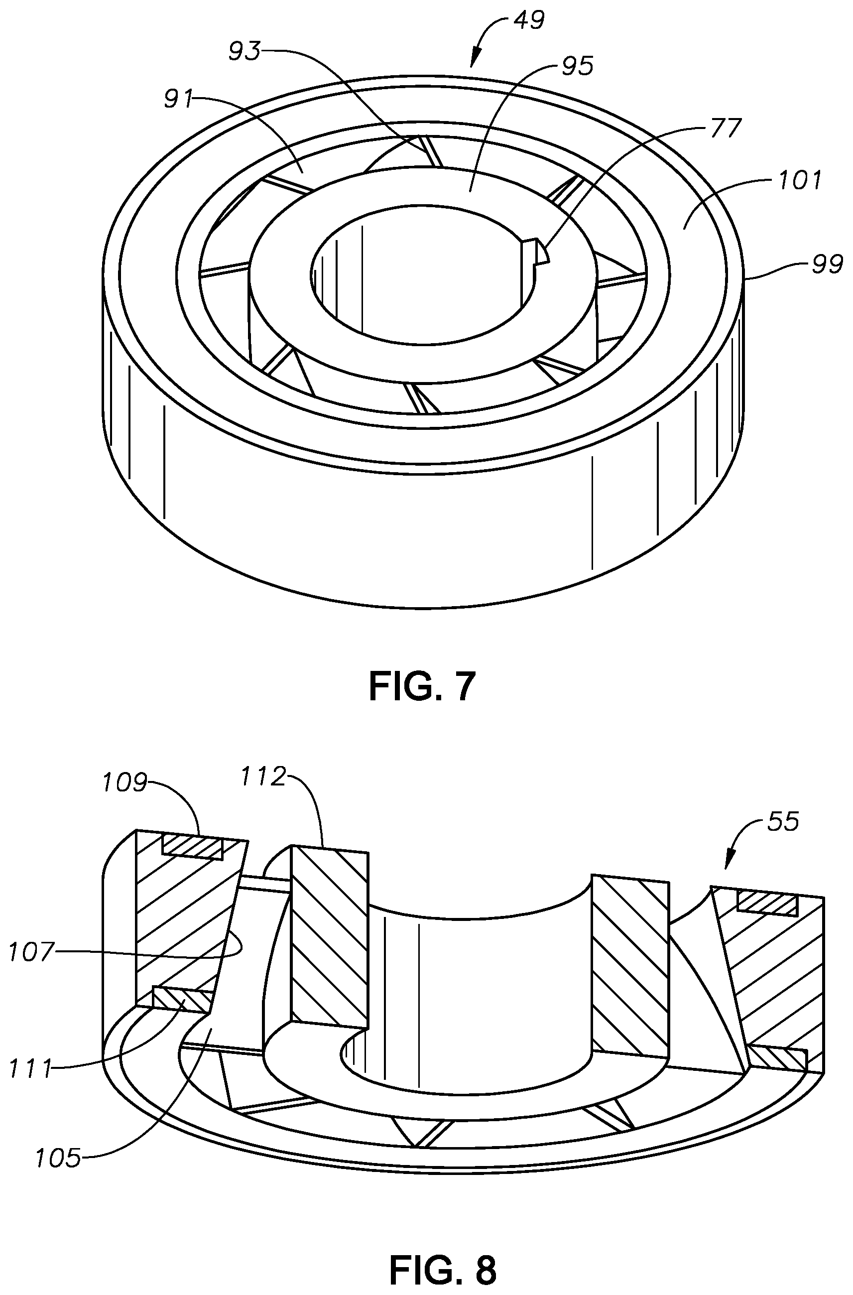
[0054] Referring to FIGS. 4 and 7, each inter-stage diffuser 49 has diffuser passages 91 that converge in an upward direction to deliver well fluid to the next upward impeller 47. Diffuser vanes 93 define diffuser passages 91 and have inner sides joined to a diffuser hub 95. Diffuser hub 95 closely receives non-rotating shaft 35. In this embodiment, key slot 77 also extends axially within the inner diameter of diffuser hub 95 to prevent rotation of inter-stage diffusers 49. Inter-stage diffusers 49 are free to move short distances axially on shaft 35 to transfer down thrust and up thrust. Each inter-stage diffuser 49 has an outer wall 99 with an outer diameter that is less than the inner diameter of impeller outer wall 79. An annular clearance exists between diffuser outer wall 99 and impeller outer wall 79. Each inter-stage diffuser 49 has a seal ring 101 on its upper side to seal against one of the impeller seal rings 85. Alternately, if impellers 47 are free to float axially relative to each other within each stage module 46, seal ring 101 would be considered to be a thrust pad for receiving down thrust from the impeller 47 located directly above it.
[0055] Referring to FIG. 8, each axially locked diffuser 55 has diffuser vanes 105 that define passages 107 that converge in an upward direction. An upper thrust pad 109 on the upper side of axially locked diffuser 55 receives down thrust from the impeller 47 (FIG. 4) directly above. Each axially locked diffuser 55 may have lower thrust pad 111 on its lower side for receiving up thrust from one of the bearing assemblies 53. In this example, vanes 105 are joined on their inner edges to a hub 112 that closely receives non-rotating shaft 35 (FIG. 4). Each axially locked diffuser 55 may be locked to non-rotating shaft 35 (FIG. 4) in various ways, such as by one or more split rings, threads or the like (not shown) in its inner diameter. Each axially locked diffuser 55 is also rotationally locked to shaft 35 in a suitable manner.
[0056] FIGS. 9-11 illustrate one example of one of the bearing locators 31 and bearing assemblies 53. Bearing locator 31 has a cylindrical inward facing inner wall 113. An axially extending slot 115 (FIG. 11) extends along the inner surface of bearing locator inner wall 113. Slot 115 has an upper end below the upper end of bearing locator inner wall 113 and a lower end above the lower end of bearing locator inner wall 113. The upper end of the intermediate bearing locator inner wall 113 as well as the outer portion containing windings slots 32 abuts the lower end of stator upper section 21a. The lower end of the intermediate bearing locator inner wall 113 as well as the outer portion containing windings slots 32 abuts the upper end of stator lower section 21b. Each bearing locator 31 may be a single-piece member.
[0057] Each bearing assembly 53 has a non-rotating outer portion 117, which is illustrated separate from other components in FIG. 11. Outer portion 117 has a cylindrical outer wall 118 that has a recess containing an anti-rotation member 119 (FIG. 9, such as a spring-biased key that snaps into engagement with bearing locator slot 115. Outer portion 117 may have an inner bearing sleeve 120 attached to it of a hard, wear-resistant material. Outer portion 117 has a thrust pad 121 on its upper side and a thrust pad 123 on its lower side. The axial dimension of outer portion 117 in this example is less than the axial length of bearing locator slot 115, allowing limited upward and downward movement of outer portion 117 relative to bearing locator 31.
[0058] FIG. 10 illustrates an inner rotating portion 125 of each bearing assembly 53, which in this example, includes an upper portion 125a and a lower portion 125b attached to each other in a suitable manner, such as by threads 127. Rotating portion 125 has a central passage 126 for the upward passage of well fluid. Rotating upper portion 125a has an annular slot 129 on its upper end, and rotating lower portion 125b has a similar annular slot 129 on its lower end. Upper slot 129 on the intermediate bearing assembly 53 receives a lower end of the stage sleeve 51 of the upper stage module 46a. Lower slot 129 on the intermediate bearing assembly 53 receives an upper end of the stage sleeve 51 of the lower stage module 46b. Pins or fasteners 131 extend laterally through holes in rotating upper portion 125a and rotating lower portion 125b and in the stage sleeves 51 to secure stage sleeves 51 to the rotating portion 125. This arrangement causes stage sleeves 51 to rotate in unison. The lower end of rotating portion 125 of the uppermost bearing assembly 53 will be pinned in the same manner to the upper end of the stage sleeve 51 of the upper stage module 46a. The upper end of the lowermost bearing assembly 53 will be pinned in the same manner to the lower end of the stage sleeve 51 of the lower stage module 46b.
[0059] Various techniques may be used to cause rotating inner portion 125a to rotate in unison with the impellers 47 in the next above and next below stage module 46. For example, a torque sleeve 133 (FIG. 9) with tabs and recesses similar to impeller tabs 87 and recess 89 (FIG. 5) may extend between mating recesses 89 on the lower end of the lowest impeller 47 of upper stage module 46a and tabs (not shown) on the upper end of upper bearing rotating portion 125a. The lower end of lower bearing rotating portion 125b may have recesses (not shown) to engage mating tabs 87 on the upper end of the uppermost impeller 47 of lower stage module 46b.
[0060] Bearing assemblies 53 are free to move axially relative to shaft 35 a slight distance to transfer down thrust and up thrust. For example, upper bearing rotating portion 125a has a downward facing thrust pad 135 that slidingly engages non-rotating portion thrust pad 121. Lower bearing rotating portion 125b has an upward facing thrust pad 137 to transfer to non-rotating portion thrust pad 123 any up thrust due to upward flowing well fluid in central passage 126. Upper bearing rotating portion 125a has an upper thrust pad 138 that will slidingly engage axially locked diffuser thrust pad 111 to transfer any up thrust.
[0061] Upper rotating bearing portion 125a has a hub 139 that receives shaft 35. In this example, the inner diameter of hub 139 slidingly engages a protective hard metal sleeve 141 that surrounds non-rotating shaft 35 and is keyed to it for non-rotation. Rotating bearing portion 125 also has a bearing sleeve 143 that may be of a hard, wear resistant material and slidingly and rotationally engages non-rotating bearing sleeve 120.
[0062] In operation, electrical power supplied to stator windings 29 interacts with permanent magnets 81 to cause impellers 47 to rotate relative to non-rotating shaft 35. Interlocking tabs 87 and recesses 89 on each impeller 47 cause the impellers 47 within each stage module 46a, 46b to rotate in unison. The rotating portion 125 of intermediate bearing 53 rotationally locks the impellers 47 of stage module 46a with those of stage module 46b. Because of the anti-rotational locking engagement of inter-stage diffusers 49 with non-rotating shaft 35, well fluid flows into intake 45 and is pumped out discharge passage 33. In this embodiment, each impeller 47 transfers down thrust to the inter-stage diffuser 49 directly below. Each inter-stage diffuser 49 transfers the down thrust to the impeller 47 directly below. The lowermost diffuser 55 is axially locked to shaft 35 and transfers the cumulative down thrust from its stage module 46a, 46b to shaft 35.
[0063] Pump 11 could be suspended within a well, either vertically, horizontally, or at inclinations. Alternately, pump 11 could be mounted in a capsule, canister or flowline jumper, such as capsule 147 (FIG. 12). Capsule 147 is a tubular enclosure containing pump 11 normally to boost the pressure of well fluid flowing from a subsea well. Capsule 147 may be located on or near the sea bed in a horizontal inclination. Capsule 147 has a cylindrical housing 149 with an end member or bulkhead 151 at one end. Bulkhead 151 has a discharge passage 153 connected to a flowline or discharge pipe 155. Bulkhead 151 also has an intake passage 157 connected to a flowline or intake pipe 159.
[0064] Pump 11 has a flange 161 that bolts pump 11 to the inner side of bulkhead 151. Discharge passage 153 is coaxial with discharge passage 33 (FIG. 1A) in discharge member 17. Additional support that isn't shown may be employed to maintain pump 11 coaxial with discharge passage 153. Intake ports 45 of intake member 41 are within the interior of capsule 147 for receiving well fluid flowing through bulkhead intake passage 157.
[0065] In the alternate embodiment of FIG. 13, capsule 163 is similar to capsule 151 (FIG. 12). Bulkhead 165 has two parallel ports; however, port 167 is an intake port and port 169 a discharge port. Pump 171 may be similar to pump 11, except intake member 173 bolts to the inner side of bulkhead 165 instead of discharge member 175. Intake member 173 has a coaxial intake port 174 on its end rather than lateral ports such as ports 45 in FIG. 12. Flange 176 secures intake member 173 to the inner side of bulkhead 165 with intake port 174 in registry with bulkhead intake port 167. Discharge member 175 is located within the interior of capsule 163.
[0066] FIG. 14 illustrates another embodiment of a mounting system for a capsule. Capsule 177 has a tubular housing 179 with a bulkhead 181 on one end. Bulkhead 181 has only a single flow passage 183, which is employed as an intake. A second end or bulkhead 185 has a discharge passage 187. A discharge tube 189 on discharge member 190 of pump 191 extends coaxially through discharge passage 187. A flange 193 bolts an intake member 195 of pump 191 to the inner side of bulkhead 181. Intake passage 183 is coaxial with pump 191.
[0067] While a few embodiments of the disclosure have been given for purposes of disclosure, numerous changes exist in the details of procedures for accomplishing the desired results. These and other similar modifications will readily suggest themselves to those skilled in the art, and are intended to be encompassed within the spirit of the present disclosure disclosed herein and the scope of the appended claims.
* * * * *
D00000
D00001
D00002
D00003
D00004
D00005
D00006
D00007
D00008
XML
uspto.report is an independent third-party trademark research tool that is not affiliated, endorsed, or sponsored by the United States Patent and Trademark Office (USPTO) or any other governmental organization. The information provided by uspto.report is based on publicly available data at the time of writing and is intended for informational purposes only.
While we strive to provide accurate and up-to-date information, we do not guarantee the accuracy, completeness, reliability, or suitability of the information displayed on this site. The use of this site is at your own risk. Any reliance you place on such information is therefore strictly at your own risk.
All official trademark data, including owner information, should be verified by visiting the official USPTO website at www.uspto.gov. This site is not intended to replace professional legal advice and should not be used as a substitute for consulting with a legal professional who is knowledgeable about trademark law.