Kickover Tools and Methods of Operating the Same in Hydrocarbon Wells
Romer; Michael C. ; et al.
U.S. patent application number 16/803067 was filed with the patent office on 2020-10-29 for kickover tools and methods of operating the same in hydrocarbon wells. The applicant listed for this patent is ExxonMobil Upstream Research Company. Invention is credited to Tony W. Hord, Michael C. Romer.
| Application Number | 20200340317 16/803067 |
| Document ID | / |
| Family ID | 1000004685009 |
| Filed Date | 2020-10-29 |


| United States Patent Application | 20200340317 |
| Kind Code | A1 |
| Romer; Michael C. ; et al. | October 29, 2020 |
Kickover Tools and Methods of Operating the Same in Hydrocarbon Wells
Abstract
Kickover tools and methods of operating the same. The kickover tools are configured to engage a downhole component within a completion structure of a hydrocarbon well. The kickover tools include a tool body and a kickover arm that extends between a first arm end and a second arm end. The kickover tools also include an end effector that is operatively attached to the second arm end and configured to interface with the downhole component. The kickover tools further include an actuation mechanism that mechanically couples the first arm end to the tool body and is configured to selectively transition the kickover arm between a retracted configuration and an extended configuration. The kickover tools also include a data transmission interface and an attachment point. The kickover tools further include an imaging device configured to collect an image indicative of an environment proximal the kickover tool.
| Inventors: | Romer; Michael C.; (The Woodlands, TX) ; Hord; Tony W.; (Spring, TX) | ||||||||||
| Applicant: |
|
||||||||||
|---|---|---|---|---|---|---|---|---|---|---|---|
| Family ID: | 1000004685009 | ||||||||||
| Appl. No.: | 16/803067 | ||||||||||
| Filed: | February 27, 2020 |
Related U.S. Patent Documents
| Application Number | Filing Date | Patent Number | ||
|---|---|---|---|---|
| 62839410 | Apr 26, 2019 | |||
| Current U.S. Class: | 1/1 |
| Current CPC Class: | E21B 47/12 20130101; E21B 23/03 20130101; E21B 43/123 20130101 |
| International Class: | E21B 23/03 20060101 E21B023/03; E21B 47/12 20060101 E21B047/12; E21B 43/12 20060101 E21B043/12 |
Claims
1. A kickover tool configured to engage a downhole component within a completion structure of a hydrocarbon well, the kickover tool comprising: a tool body; a kickover arm that extends between a first arm end and a second arm end; an end effector configured to interface with the downhole component, wherein the end effector is operatively attached to the second arm end; an actuation mechanism that mechanically couples the first arm end of the kickover arm to the tool body and is configured to selectively transition the kickover arm between a retracted configuration and an extended configuration; a data transmission interface; an attachment point configured to operatively interconnect the kickover tool with an umbilical; and an imaging device configured to collect a collected image indicative of an environment proximal the kickover tool, to generate an image signal indicative of the collected image, and to provide the image signal to the data transmission interface.
2. The kickover tool of claim 1, wherein the image signal includes information indicative of a spatial relationship between at least one of: (i) the kickover tool and the completion structure; (ii) the end effector and the completion structure; and (iii) the end effector and the downhole component.
3. The kickover tool of claim 1, wherein the image signal includes information indicative of at least one of: (i) a visual representation of the kickover tool; (ii) a visual representation of the tool body; (iii) a visual representation of the kickover arm; (iv) a visual representation of the completion structure; and (v) a visual representation of the downhole component.
4. The kickover tool of claim 1, wherein the imaging device includes at least one of: (i) an optical imaging device configured to collect visible light; (ii) an electromagnetic imaging device configured to collect electromagnetic radiation; (iii) an infrared imaging device configured to collect infrared radiation; and (iv) an acoustic imaging device configured to detect acoustic vibrations.
5. The kickover tool of claim 1, wherein the imaging device includes an active imaging device configured to provide a probe signal to the environment proximal the kickover tool such that the probe signal reflects from at least one structure within the environment proximal to the kickover tool to generate a reflected signal, wherein the imaging device further is configured to receive the reflected signal and to generate the image signal based, at least in part, on the reflected signal.
6. The kickover tool of claim 5, wherein the probe signal includes at least one of electromagnetic radiation and acoustic vibration.
7. The kickover tool of claim 1, wherein the imaging device includes a passive imaging device configured to generate the image signal responsive to receipt of at least one of: (i) ambient vibrations within the environment proximal the kickover tool; and (ii) ambient electromagnetic radiation within the environment proximal the kickover tool.
8. The kickover tool of claim 1, wherein the kickover tool further includes a tension sensor configured to generate a tension signal indicative of a tensile force between the attachment point and the umbilical and to provide the tension signal to the data transmission interface.
9. The kickover tool of claim 8, wherein the tension sensor includes a strain sensor configured to detect mechanical strain within at least a portion of at least one of the kickover tool, the attachment point, and the umbilical.
10. The kickover tool of claim 1, wherein the kickover tool further includes a pressure sensor configured to generate a pressure signal indicative of a pressure acting upon the pressure sensor and to provide the pressure signal to the data transmission interface.
11. The kickover tool of claim 1, wherein the kickover tool further includes a depth sensor configured to generate a depth signal indicative of a depth of the kickover tool within the hydrocarbon well and to provide the depth signal to the data transmission interface.
12. The kickover tool of claim 1, wherein the kickover tool further includes an orientation-determining structure configured to generate an orientation signal and to provide the orientation signal to the data transmission interface, wherein the orientation signal is indicative of at least one of: (i) a relative orientation between the tool body and the kickover arm; (ii) a relative orientation between the end effector and the kickover arm; (iii) a relative orientation between the end effector and the tool body; (iv) a relative orientation between the kickover arm and the downhole component; (v) a relative orientation between the end effector and the downhole component; (vi) a body-arm angle defined between a body longitudinal axis of the tool body and an arm longitudinal axis of the kickover arm; and (vii) an arm-end effector angle defined between the arm longitudinal axis and an end effector longitudinal axis of the end effector.
13. The kickover tool of claim 1, wherein the kickover tool further includes a temperature sensor configured to generate a temperature signal indicative of a temperature in the environment proximal the kickover tool and to provide the temperature signal to the data transmission interface.
14. The kickover tool of claim 1, wherein the kickover tool further includes an acceleration sensor configured to generate an acceleration signal indicative of an acceleration of the kickover tool and to provide the acceleration signal to the data transmission interface.
15. The kickover tool of claim 1, wherein the kickover tool further includes a velocity sensor configured to generate a velocity signal indicative of a velocity of the kickover tool and to provide the velocity signal to the data transmission interface.
16. The kickover tool of claim 1, wherein the kickover tool further includes a communication structure configured to facilitate communication with the downhole component when the kickover tool is proximal the downhole component within the hydrocarbon well.
17. The kickover tool of claim 16, wherein the communication structure includes an inductive communication structure.
18. The kickover tool of claim 1, wherein the kickover tool further includes an analysis structure programmed to receive the image signal from the imaging device, to modify the image signal to generate a modified image signal, and to provide the modified image signal to the data transmission interface.
19. A hydrocarbon well, comprising: a wellbore extending between a surface region and a subsurface region; the kickover tool of claim 1 positioned within the wellbore; the umbilical operatively attached to the attachment point and extending from the kickover tool to the surface region; a downhole tubular extending within the wellbore; the completion structure operatively attached to the downhole tubular; and the downhole component positioned within the completion structure.
20. A method of operating a kickover tool, the method comprising: positioning the kickover tool within a completion structure of a hydrocarbon well; collecting, with the kickover tool, a collected image indicative of an environment within the hydrocarbon well and proximal the kickover tool; displaying, for an operator of the kickover tool, a displayed image that is based upon the collected image and is indicative of the environment within the hydrocarbon well and proximal the kickover tool; and at least one of: (i) interfacing the kickover tool with a downhole component of the completion structure while the kickover tool is positioned within the completion structure, wherein the interfacing is based, at least in part, on the displaying; and (ii) installing the downhole component within the completion structure, wherein the installing is based, at least in part, on the displaying.
21. The method of claim 20, wherein the positioning includes conveying the kickover tool along a length of a wellbore of the hydrocarbon well, and further wherein the method further includes detecting, with the kickover tool and during the conveying, at least one of: (i) a pressure within the wellbore; (ii) a temperature within the wellbore; (iii) a velocity of the kickover tool; (iv) an acceleration of the kickover tool; and (v) a depth of the kickover tool.
22. The method of claim 20, wherein the method further includes detecting an orientation of the kickover tool with an orientation-determining structure of the kickover tool, and further wherein the interfacing is based, at least in part, on the detected orientation.
23. The method of claim 20, wherein the method further includes detecting, with the kickover tool, a tension within a region of the kickover tool.
24. The method of claim 23, wherein the method further includes displaying, for the operator of the kickover tool, the tension within the region of the kickover tool.
Description
CROSS-REFERENCE TO RELATED APPLICATION
[0001] This application claims the benefit of U.S. Provisional Application 62/839,410 filed Apr. 26, 2019 entitled KICKOVER TOOLS AND METHODS OF OPERATING THE SAME IN HYDROCARBON WELLS, the entirety of which is incorporated by reference herein.
FIELD OF THE DISCLOSURE
[0002] The present disclosure relates generally to kickover tools and to methods of operating kickover tools in hydrocarbon wells.
BACKGROUND OF THE DISCLOSURE
[0003] Kickover tools may be utilized to engage and/or to interface with a downhole component within a completion structure of a hydrocarbon well. As an example, kickover tools may be utilized to insert and/or to remove a gas lift valve from a side pocket mandrel of the hydrocarbon well. Gas lift valves may be utilized to provide artificial (gas) lift to hydrocarbon fluids that may be present within a subterranean formation. These gas lift valves periodically may need to be removed, such as to adjust, inspect, or replace the gas lift valve. Conventional kickover tools utilized for these purposes are wireline-attached devices that provide an operator with very little feedback other than the tension on the wireline that is measured external to the well, such as at a surface region. As such, gas lift valve removal and/or installation is a highly specialized process requiring skilled and/or experienced operators, and problems still occur. These problems, including loss of the kickover tool within the hydrocarbon well and/or an inability to insert, or remove, a given gas lift valve from a given side pocket mandrel may be costly and time-consuming to overcome. Thus, there exists a need for improved kickover tools and for methods of operating the improved kickover tools.
SUMMARY OF THE DISCLOSURE
[0004] Kickover tools and methods of operating the same. The kickover tools are configured to engage a downhole component within a completion structure of a hydrocarbon well. The kickover tools include a tool body and a kickover arm that extends between a first arm end and a second arm end. The kickover tools also include an end effector that is operatively attached to the second arm end and configured to interface with the downhole component. The kickover tools further include an actuation mechanism that mechanically couples the first arm end to the tool body and is configured to selectively transition the kickover arm between a retracted configuration and an extended configuration. The kickover tools also include a data transmission interface and an attachment point configured to operatively interconnect the kickover tool with an umbilical. The kickover tools further include an imaging device configured to collect a collected image that is indicative of an environment proximal the kickover tool, to generate an image signal indicative of the image, and to provide the image signal to the data transmission interface.
[0005] The methods include positioning the kickover tool within a completion structure of a hydrocarbon well and collecting, with the kickover tool, a collected image indicative of an environment within the hydrocarbon well and proximal the kickover tool. The methods also include displaying, for an operator of the kickover tool, a displayed image that is based upon the collected image. The methods further include interfacing the kickover tool with a downhole component of the completion structure. The interfacing is based, at least in part, on the displaying.
BRIEF DESCRIPTION OF THE DRAWINGS
[0006] FIG. 1 is a schematic illustration of examples of a hydrocarbon well that may include and/or utilize a kickover tool, according to the present disclosure.
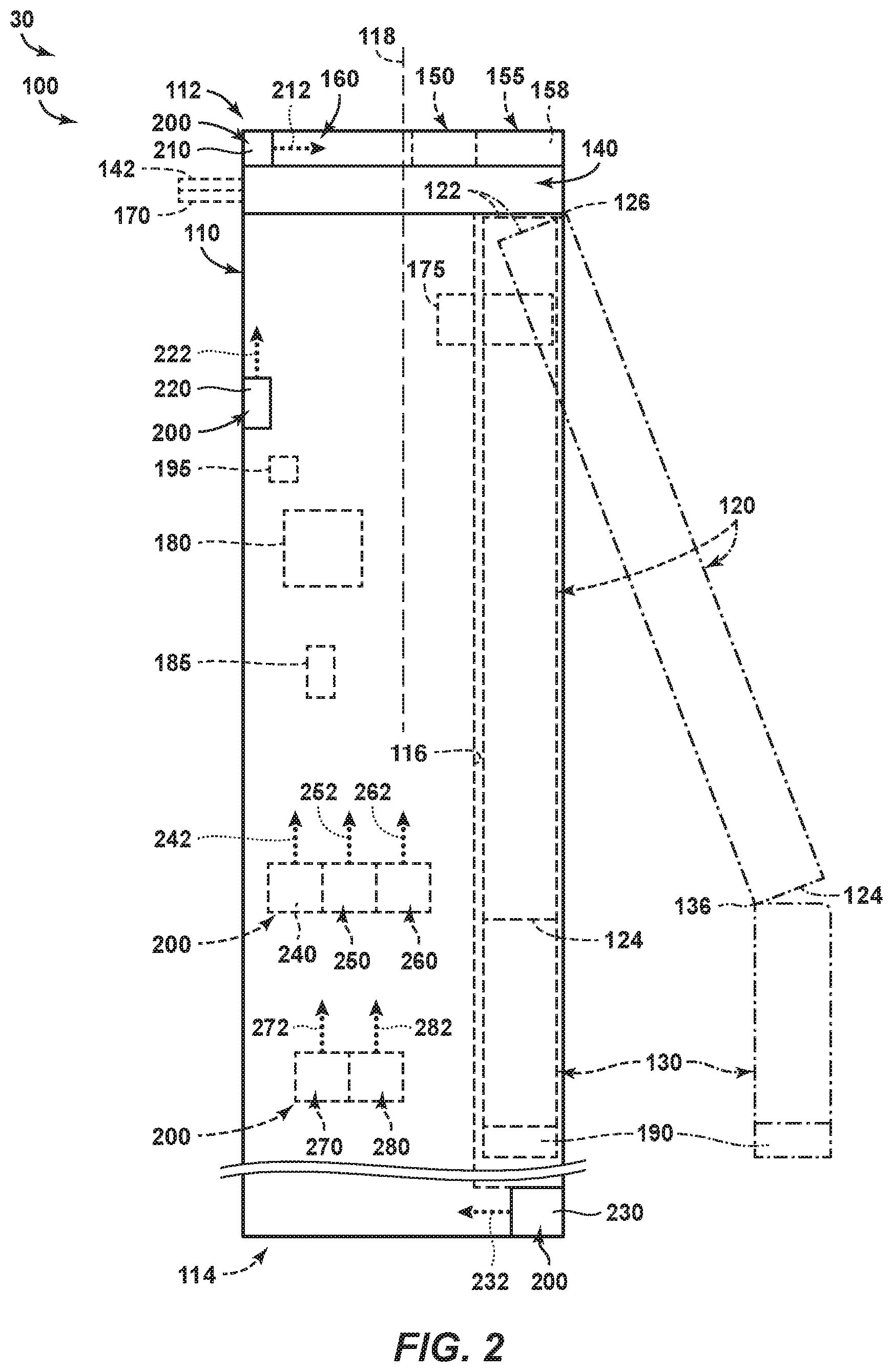
[0007] FIG. 2 is a schematic illustration of examples of a kickover tool according to the present disclosure.
[0008] FIG. 3 is a flowchart depicting examples of methods of operating a kickover tool, according to the present disclosure.
[0009] FIG. 4 is a schematic illustration of a portion of the method of FIG. 3.
[0010] FIG. 5 is a schematic illustration of a portion of the method of FIG. 3.
[0011] FIG. 6 is a schematic illustration of a portion of the method of FIG. 3.
[0012] FIG. 7 is a schematic illustration of a portion of the method of FIG. 3.
DETAILED DESCRIPTION AND BEST MODE OF THE DISCLOSURE
[0013] FIGS. 1-7 provide examples of kickover tools 100, of hydrocarbon wells 30 that include kickover tools 100, and/or of methods 300, according to the present disclosure. Elements that serve a similar, or at least substantially similar, purpose are labeled with like numbers in each of FIGS. 1-7, and these elements may not be discussed in detail herein with reference to each of FIGS. 1-7. Similarly, all elements may not be labeled in each of FIGS. 1-7, but reference numerals associated therewith may be utilized herein for consistency. Elements, components, and/or features that are discussed herein with reference to one or more of FIGS. 1-7 may be included in and/or utilized with any of FIGS. 1-7 without departing from the scope of the present disclosure. In general, elements that are likely to be included in a particular embodiment are illustrated in solid lines, while elements that are optional are illustrated in dashed lines. However, elements that are shown in solid lines may not be essential and, in some embodiments, may be omitted without departing from the scope of the present disclosure.
[0014] FIG. 1 is a schematic illustration of examples of a hydrocarbon well 30 that may include and/or utilize a kickover tool 100, according to the present disclosure. FIG. 2 is a more detailed, but still schematic, illustration of examples of kickover tools 100.
[0015] As illustrated in FIG. 1, hydrocarbon well 30 includes a wellbore 40 that extends within a subsurface region 20. Wellbore 40 also may be referred to herein as extending between a surface region 10 and subsurface region 20. Kickover tool 100 is positioned within wellbore 40, and hydrocarbon well 30 also includes an umbilical 85 that extends from the kickover tool and/or toward, or to, surface region 10.
[0016] Hydrocarbon well 30 also include a downhole tubular 50 that extends within wellbore 40. A completion structure 60 is operatively attached to and/or forms a portion of the downhole tubular, and a downhole component 70 is positioned within and/or operatively attached to the completion structure.
[0017] Kickover tool 100 is configured to engage, or to operatively engage, with downhole component 70 while the downhole component is within completion structure 60 of hydrocarbon well 30. With reference to FIGS. 1-2, kickover tool 100 includes a tool body 110 and a kickover arm 120 that extends between a first arm end 122 and a second arm end 124.
[0018] Kickover tool 100 also includes an end effector 130. End effector 130 is operatively attached to second arm end 124 and is configured to interface, or to selectively interlock, with downhole component 70, as discussed in more detail herein.
[0019] Kickover tool 100 further includes an actuation mechanism 140. Actuation mechanism 140 operatively and/or mechanically couples first arm end 122 of kickover arm 120 to tool body 110 and is configured to selectively transition the kickover arm between a retracted configuration, as illustrated in dashed lines in FIG. 2, and an extended configuration, as illustrated in dash-dot lines in FIG. 2.
[0020] Kickover tool 100 also includes a data transmission interface 150, an attachment point 160, and a sensor 200, such as an imaging device 230. Data transmission interface 150 may be configured to facilitate communication between kickover tool 100 and surface region 10, as discussed in more detail herein. Attachment point 160 may be configured to operatively interconnect kickover tool 100 with umbilical 85. Stated another way, umbilical 85 may be operatively attached to the attachment point of the kickover tool, as illustrated in FIG. 1.
[0021] Imaging device 230 may be configured to collect a collected image indicative of an environment proximal kickover tool 100. Imaging device 230 also may be configured to generate an image signal 232 that is indicative of and/or based upon the collected image. Imaging device 230 further may be configured to provide the image and/or the image signal to data transmission interface 150. During operation of kickover tool 100, a displayed image, which may be based upon the image signal, may be utilized, such as by an operator of the kickover tool, to permit and/or facilitate interfacing between the kickover tool and downhole component 70, removal of the downhole component from the completion structure utilizing the kickover tool, and/or installation of the downhole component within the completion structure utilizing the kickover tool.
[0022] Completion structure 60 may include any suitable structure that may be operatively attached to downhole tubular 50, that may at least partially define downhole tubular 50, that may contain downhole component 70, and/or that may be operatively attached to downhole component. Examples of completion structure 60 include a mandrel or a side pocket mandrel.
[0023] Downhole component 70 may include any suitable structure that may be positioned within completion structure 60 and/or that may be operatively attached to the completion structure. Examples of downhole component 70 include a valve or a gas lift valve.
[0024] As illustrated in dashed lines in FIG. 1, hydrocarbon well 30 may include an electrical cable 80. Electrical cable 80, when present, may include and/or be a data transmission cable that may include at least one data electrical conductor configured to convey image signal 232 between kickover tool 100 and surface region 10. When hydrocarbon well 30 includes electrical cable 80, the electrical cable may be in electrical communication with, or may be electrically connected to, data transmission interface 150. Additionally or alternatively, data transmission interface 150 may be configured to provide image signal 232 to the electrical cable. Additionally or alternatively, electrical cable 80 may include and/or be a power cable that may include at least one power electrical conductor configured to provide electrical power to kickover tool 100, such as from surface region 10.
[0025] It is within the scope of the present disclosure that umbilical 85 may be defined by, or may be, electrical cable 80. Additionally or alternatively, it is also within the scope of the present disclosure that umbilical 85 may be distinct, separate, and/or spaced-apart from electrical cable 80, as illustrated in dashed lines in FIG. 1. Other examples of umbilical 85 include a wireline, slickline, digital slickline that is configured to convey data, and/or coiled tubing.
[0026] As illustrated in dashed lines in FIG. 1, hydrocarbon well 30 may include a wireless data transmission structure 88. Wireless data transmission structure 88, when present, may be in wireless communication with data transmission interface 150, may be configured to receive image signal 232, in the form of a wireless image signal 232, from data transmission interface 150, and/or may be configured to convey the image signal between the kickover tool and the surface region. Examples of wireless data transmission structure 88 include a radio frequency wireless data transmission structure, a wireless data transmission structure configured to transmit electromagnetic radiation, and/or a wireless data transmission structure configured to transmit acoustic vibrations.
[0027] As illustrated in dashed lines in FIG. 1, hydrocarbon well 30 may include a power supply structure 90. Power supply structure 90, when present, may be configured to provide electric power to kickover tool 100, such as via electrical cable 80. Examples of power supply structure 90 include a battery, an electric generator, and/or a main power source.
[0028] As also illustrated in dashed lines in FIG. 1, hydrocarbon well 30 may include a data analysis structure 92. Data analysis structure 92, when present, may be configured to receive the image signal from the data transmission interface of the kickover tool. Data analysis structure 92 additionally or alternatively may be configured to analyze the image signal and/or to process the image signal. Examples of data analysis structure 92 include any suitable computer, personal computer, and/or logic device that may be programmed to analyze the image signal and/or to process the image signal.
[0029] As also illustrated in FIG. 1, hydrocarbon well 30 may include a display 94. Display 94, when present, may be configured to generate and/or to display a displayed image that is based, at least in part, on the image signal. This displayed image may be viewed and/or observed by the operator of kickover tool 100, such as to permit and/or to facilitate interfacing between the kickover tool and downhole component 70, removal of the downhole component from completion structure 60, and/or installation of the downhole component within the completion structure, as discussed in more detail herein. Examples of display 94 include a screen, a television screen, and/or a computer monitor.
[0030] Data transmission interface 150 may include any suitable structure that may be adapted, configured, designed, and/or constructed to convey image signal 232 from kickover tool 100 and/or to surface region 10. As an example, data transmission interface 150 may include a wired data transmission interface configured to transmit wired image signal 232 from the kickover tool and/or to the surface region, such as via electrical cable 80 of FIG. 1 and/or the data transmission cable that may be formed thereby. As another example, data transmission interface 150 may include a wireless data transmission interface configured to transmit wireless image signal 232 from the kickover tool and/or to the surface region, such as via wireless data transmission structure 88 of FIG. 1.
[0031] Imaging device 230 may include any suitable structure that may be adapted, configured, designed, and/or constructed to collect the collected image, to generate image signal 232 based upon the collected image, and/or to provide the image signal to the data transmission interface. Examples of imaging device 230 include an optical imaging device configured to collect visible light, an electromagnetic imaging device configured to collect electromagnetic radiation, an infrared imaging device configured to collect infrared radiation, and/or an acoustic imaging device configured to detect acoustic vibrations.
[0032] Stated another way, and as examples, imaging device 230 may be configured to collect and/or to receive electromagnetic radiation and/or acoustic vibration, such as from the environment proximal the kickover tool, and to convert this electromagnetic radiation and/or acoustic vibration to image signal 232. Examples of such imaging devices 230 include a microphone, a directional microphone, a solid state acoustic sensor, a camera, a video camera, and/or a charge coupled device.
[0033] It is within the scope of the present disclosure that imaging device 230 may include and/or be an active imaging device. Such an active imaging device may be configured to provide a probe signal to the environment proximal the kickover tool. The probe signal may reflect from at least one structure within the environment proximal the kickover tool to generate a reflected signal, and the imaging device further may be configured to receive the reflected signal and to generate the image signal based, at least in part, on the reflected signal. Examples of the probe signal include electromagnetic radiation and/or acoustic vibration.
[0034] Additionally or alternatively, it is also within the scope of the present disclosure that imaging device 230 may include and/or be a passive imaging device. Such a passive imaging device may be configured to generate the image signal responsive to receipt of and/or based upon ambient vibrations within the environment proximal the kickover tool and/or ambient electromagnetic radiation within the environment proximal the kickover tool.
[0035] The image signal may include any suitable information. As an example, the image signal may include information indicative of a spatial relationship between the kickover tool and the completion structure, between the end effector and the completion structure, and/or between the end effector and the downhole component. As another example, the image signal may include information indicative of a visual representation of the kickover tool, a visual representation of the tool body, a visual representation of the kickover arm, a visual representation of the end effector, a visual representation of the completion structure, and/or a visual representation of the downhole component.
[0036] Attachment point 160 may include any suitable structure that may, or that may be utilized to, operatively interconnect, or attach, kickover tool 100 and umbilical 85. Attachment point 160 also may be referred to herein as an attachment location 160, an attachment structure 160, a coupling point 160, a coupling structure 160, and/or a coupling location 160. Examples of attachment point 160 include any suitable eye, coupler, hook, clasp, recess configured to receive at least a portion of the umbilical, and/or projection configured to be received within at least a portion of the umbilical.
[0037] Turning more specifically to FIG. 2, kickover tools 100, according to the present disclosure, optionally may include a variety of additional and/or optional structures. These structures are illustrated schematically in FIG. 2, and any of the structures and/or functions of kickover tools 100 illustrated in FIG. 2 and/or discussed herein with reference thereto may be included in and/or utilized with kickover tools 100 of FIG. 1 without departing from the scope of the present disclosure. Similarly, any structure and/or function of kickover tools 100 that is illustrated in FIG. 1 and/or discussed herein with reference thereto may be included in and/or utilized with kickover tools 100 of FIG. 2 without departing from the scope of the present disclosure.
[0038] As illustrated in dashed lines in FIG. 1, kickover tools 100 may include a power supply interface 155. Power supply interface 155, when present, may be configured to provide electric power to the kickover tool. Kickover tool 100 may be configured to receive and/or to utilize the electric power. As an example, sensor 200 and/or imaging device 230 thereof may be configured to receive and/or to utilize the electric power, such as to generate image signal 232.
[0039] This electric power may be provided to the kickover tool from power supply structure 90 of FIG. 1 and/or via electrical cable 80 of FIG. 1. In such a configuration, power supply interface 155 may be configured to electrically interconnect the kickover tool with the electric cable, which also may be referred to herein as, may include, and/or may be a power supply cable. Additionally or alternatively, kickover tool 100 may include a battery 158 that may be configured to provide the electric power to the power supply interface.
[0040] It is within the scope of the present disclosure that power supply interface 155 may be distinct and/or separate from data transmission interface 150. Additionally or alternatively, it is also within the scope of the present disclosure that the power supply interface may be at least partially defined by and/or may include the data transmission interface.
[0041] As discussed herein, kickover tool 100 includes at least one sensor 200 in the form of imaging device 230. It is within the scope of the present disclosure that kickover tool 100 may include one or more other and/or additional sensors 200, examples of which are discussed in more detail herein. Sensors 200 also may be referred to herein as detectors 200 and/or as transducers 200.
[0042] As an example, kickover tool 100 may include a sensor 200 in the form of a tension sensor 210. Tension sensor 210, when present, may be configured to generate a tension signal 212. Tension signal 212 may be indicative of a tensile force between attachment point 160 and umbilical 85 (which is illustrated in FIG. 1) and to provide the tension signal to data transmission interface 150. Data transmission interface 150 then may convey the tension signal to the surface region. An example of tension sensor 210 includes a strain sensor, and tension sensor 210 may be configured to detect mechanical strain within at least a portion of kickover tool 100, attachment point 160, and/or umbilical 85.
[0043] Knowledge of the tensile force between attachment point 160 and umbilical 85, such as via tension signal 212, may facilitate improved operation of kickover tool 100. As an example, with knowledge of the tensile force, an operator of the kickover tool may avoid damage to the kickover tool and/or to the umbilical while the kickover tools is being utilized within the hydrocarbon well. As a more specific example, the operator of the kickover tool may utilize tension signal 212 to maintain the tensile force between attachment point 160 and umbilical 85 below a threshold tensile force known to provide safe and/or damage-free operation.
[0044] As another example, kickover tool 100 may include a sensor 200 in the form of a pressure sensor 220. Pressure sensor 220, when present, may be configured to generate a pressure signal 222. Pressure signal 222 may be indicative of a pressure acting upon the pressure sensor, such as an ambient pressure within the environment proximal the kickover tool. Pressure sensor 220 may provide the pressure signal to data transmission interface 150. Data transmission interface 150 then may convey the pressure signal to the surface region.
[0045] Knowledge of the pressure within the environment proximal the kickover tool may permit an operator of the kickover tool to equalize pressure across a downhole tubular that contains the kickover tool prior to insertion and/or removal of the downhole component utilizing the kickover tool.
[0046] As yet another example, kickover tool 100 may include a sensor 200 in the form of a depth sensor 240. Depth sensor 240, when present, may be configured to generate a depth signal 242. Depth signal 242 may be indicative of a depth of the kickover tool within the hydrocarbon well. Depth sensor 240 may provide the depth signal to data transmission interface 150. Data transmission interface 150 then may convey the depth signal to the surface region.
[0047] Depth sensor 240 may include and/or be any suitable structure. Examples of depth sensor 240 include a casing collar locator and/or a pressure sensor, such as pressure sensor 220.
[0048] As another example, kickover tool 100 may include a sensor 200 in the form of an orientation-determining structure 250. Orientation-determining structure 250, when present, may be configured to generate an orientation signal 252. Orientation-determining structure 250 may provide orientation signal 252 to data transmission interface 150. Data transmission interface 150 then may convey the orientation signal to the surface region.
[0049] Orientation-determining structure 250 may be configured to determine, and/or orientation signal 252 may be indicative of, any suitable relative orientation and/or spatial relationship of and/or between kickover tool 100, completion structure 60, and/or downhole component 70. As examples, orientation signal 252 may be indicative of a relative orientation between the tool body and the kickover arm, a relative orientation between the end effector and the kickover arm, a relative orientation between the end effector and the tool body, a relative orientation between the kickover arm and the downhole component, a relative orientation between the end effector and the downhole component, a body-arm angle defined between a body longitudinal axis of the tool body and an arm longitudinal axis of the kickover arm, and/or an arm-end effector angle defined between the arm longitudinal axis and an end effector longitudinal axis of the end effector. Examples of orientation-determining structure 250 include any suitable proximity sensor and/or angle-measuring sensor.
[0050] As yet another example, kickover tool 100 may include a sensor 200 in the form of a temperature sensor 260. Temperature sensor 260, when present, may be configured to generate a temperature signal 262. Temperature signal 262 may be indicative of a temperature in the environment proximal the kickover tool. Temperature sensor 260 may provide the temperature signal to data transmission interface 150. Data transmission interface 150 then may convey the temperature signal to the surface region. Examples of temperature sensor 260 include any suitable thermocouple, resistance thermal detector (RTD), and/or infrared sensor.
[0051] Knowledge of the temperature in the environment proximal the kickover tool may be utilized to detect gas leakage within the hydrocarbon well. Such gas leakage may produce localized temperature variation, or cooling, within the hydrocarbon well, such as may be caused by Joule-Thompson cooling effects.
[0052] As another example, kickover tool 100 may include a sensor 200 in the form of an acceleration sensor 270. Acceleration sensor 270, when present, may be configured to generate an acceleration signal 272. Acceleration signal 272 may be indicative of acceleration of the kickover tool within the hydrocarbon well. Acceleration sensor 270 may provide the acceleration signal to data transmission interface 150. Data transmission interface 150 then may convey the acceleration signal to the surface region. Examples of acceleration sensor 270 include an accelerometer and/or a casing collar locator.
[0053] As yet another example, kickover tool 100 may include a sensor 200 in the form of a velocity sensor 280. Velocity sensor 280, when present, may be configured to generate a velocity signal 282. Velocity signal 282 may be indicative of a velocity of the kickover tool within the hydrocarbon well. Velocity sensor 280 may provide the velocity signal to data transmission interface 150. Data transmission interface 150 then may convey the velocity signal to the surface region. Examples of velocity sensor 280 include a velocimeter and/or a casing collar locator.
[0054] As illustrated in dashed lines in FIG. 2, kickover tool 100 may include a memory device 185. Memory device 185, when present, may be configured to store at least one data signal that is generated by the kickover tool while the kickover tool is utilized within the hydrocarbon well. Such data signal may be provided to the memory device by data transmission interface 150. Examples of the at least one data signal include any data signal that may be produced and/or generated by sensors 200, such as tension signal 212, pressure signal 222, image signal 232, depth signal 242, orientation signal 252, temperature signal 262, acceleration signal 272, and/or velocity signal 282. Examples of memory device 185 include a memory chip, a solid state memory chip, a volatile memory device, and/or a nonvolatile memory device.
[0055] As also illustrated in dashed lines in FIG. 2, kickover tool 100 may include a communication structure 190. Communication structure 190, when present, may be configured to facilitate communication with the downhole component and/or between the kickover tool and the downhole component. This communication may be performed when the kickover tool is proximal the downhole component and within the hydrocarbon well. An example of communication structure 190 includes an inductive communication structure, such as an inductive coupling structure.
[0056] As also illustrated in dashed lines in FIG. 2, kickover tool 100 may include an analysis structure 195. Analysis structure 195, when present, may be configured to receive one or more data signals that may be generated by kickover tool 100, to modify the one or more data signals to generate a modified data signal, and/or to provide the modified data signal to data transmission interface 150. As an example, analysis structure 195 may receive image signal 232 from imaging device 230, may modify image signal 232 to generate a modified image signal, and may provide the modified image signal to the data transmission interface. This modification may include local and/or downhole analysis, computation, compression, simplification, encoding, and/or processing of the data signal.
[0057] Returning more generally to the examples of kickover tools 100 illustrated in FIGS. 1-2, kickover tools may include a variety of conventional structures. These conventional structures may be common to conventional kickover tools.
[0058] As an example, and as discussed, kickover tools 100 may include tool body 110. Tool body 110 may include and/or be an elongate tool body, such as may extend along a body longitudinal axis 118 and/or between an uphole body end 112 and a downhole body end 114.
[0059] In such a configuration, and as illustrated, data transmission interface 150 and/or attachment point 160 may be operatively attached to, may be proximal, and/or may at least partially define uphole body end 112.
[0060] As illustrated in dashed lines in FIGS. 1-2, tool body 110 may include and/or define an arm receptacle 116. Arm receptacle 116, when present, may be sized to receive kickover arm 120 when the kickover arm is in the retracted configuration, such as is illustrated in FIG. 1 and in dashed lines in FIG. 2. Arm receptacle 116 also may be sized to end effector 130 when the kickover arm is in the retracted configuration. Arm receptacle 116 additionally or alternatively may be sized to receive the downhole component when the end effector interfaces with the downhole component and the kickover arm is in the retracted configuration.
[0061] Kickover arm 120 may include and/or be an elongate kickover arm that extends between first arm end 122 and second arm end 124. First arm end 122 may be hingedly connected to the tool body, such as via actuation mechanism 140, such that the kickover arm pivots, relative to the tool body, about an arm hinge axis 126 upon transitioning between the retracted configuration and the extended configuration.
[0062] As discussed, end effector 130 may be configured to interface with the downhole component. It is within the scope of the present disclosure that the end effector may interface with the downhole component in any suitable manner As examples, the end effector may be configured to selectively interlock with the downhole component and/or to reliably interlock with the downhole component.
[0063] End effector 130 may be hingedly connected to second arm end 124 such that the end effector pivots, relative to the kickover arm, about an end effector hinge axis 136 when the kickover arm transitions between the retracted configuration and the extended configuration. End effector hinge axis 136 may be parallel, or at least substantially parallel, to arm hinge axis 126.
[0064] Actuation mechanism 140 may include any suitable structure that may be adapted, configured, designed, and/or constructed to mechanically couple first arm end 122 to tool body 110 and/or to selectively transition kickover arm 120 between the retracted configuration and the extended configuration. As an example, actuation mechanism 140 may include a trigger 142 that may extend from tool body 110. In such a configuration, actuation mechanism 140 may be configured to selectively transition the kickover arm from the retracted configuration to the extended configuration responsive to receipt of at least a threshold trigger force by the trigger. This trigger force may be applied to the trigger by a side pocket mandrel and/or by an orienting receptacle 62 of the side pocket mandrel, as illustrated in FIG. 1.
[0065] Kickover tool 100 further may include a biasing mechanism 175. Biasing mechanism 175, when present, may be configured to bias the kickover arm toward the extended configuration. As an example, actuation mechanism 140 may be configured to retain the kickover arm in the retracted configuration and to selectively permit the biasing mechanism to transition the kickover arm to the extended configuration, such as when greater than the threshold trigger force is applied to trigger 142.
[0066] Kickover tool 100 also may include an orientation structure 170. Orientation structure 170 may extend from tool body 110 and/or may be configured to selectively interface with orienting receptacle 62 of the completion structure 60, as illustrated in FIG. 1. This may orient the kickover arm at a predetermined orientation relative to the downhole component.
[0067] It is within the scope of the present disclosure that orientation structure 170 may include and/or may be defined by trigger 142. Additionally or alternatively, it is also within the scope of the present disclosure that orientation structure 170 may be at least partially, or even completely, separate and/or distinct from trigger 142.
[0068] As illustrated in dashed lines in FIGS. 1-2, kickover tool 100 also may include a jar mechanism 180. Jar mechanism 180, when present, may be configured to selectively provide a jarring force to the kickover tool. The jarring force may be oriented and/or directed to urge the downhole component from a component receptacle of the completion structure and/or to urge the downhole component into the component receptacle, such as to facilitate removal of the downhole component from the completion structure and/or installation of the downhole component within the completion structure.
[0069] FIG. 3 is a flowchart depicting examples of methods 300 of operating a kickover tool, according to the present disclosure. FIGS. 4-7 are schematic illustrations of kickover tools 100 performing portions of the methods of FIG. 3. Methods 300 may be performed utilizing kickover tools 100 of FIGS. 1-2, and any of the structures, functions, and/or features of kickover tools 100 discussed herein with reference to FIGS. 1-2 may be included in and/or utilized with methods 300 of FIG. 3 and/or kickover tools 100 of FIGS. 4-7 without departing from the scope of the present disclosure. Similarly, kickover tools 100 of FIGS. 1-2 may include any of the structures and/or may perform any of the functions discussed herein with reference to methods 300 of FIG. 3 and/or kickover tools 100 of FIGS. 4-7.
[0070] Methods 300 include positioning a kickover tool at 310 and may include detecting a parameter at 320. Methods 300 also include collecting a collected image at 330 and displaying the collected image as a displayed image at 340. Methods 300 further may include displaying the parameter at 350 and include interfacing the kickover tool with a downhole component at 360. Methods 300 also may include separating the downhole component from a completion structure at 370 and/or installing the downhole component within the completion structure at 380.
[0071] Positioning the kickover tool at 310 may include positioning the kickover tool within a completion structure of a hydrocarbon well. This may include conveying the kickover tool along a length of the wellbore of the hydrocarbon well, to the completion structure, and/or into the completion structure.
[0072] An example of the positioning at 310 is illustrated in FIG. 4. As illustrated therein, kickover tool 100 may be positioned within completion structure 60, which in the example of FIG. 4, is a side pocket mandrel.
[0073] Detecting the parameter at 320 may include detecting any suitable parameter with the kickover tool and/or in the hydrocarbon well. Examples of the parameter include a pressure within the wellbore, a temperature within the wellbore, a velocity of the kickover tool, an acceleration of the kickover tool, and/or a depth of the kickover tool.
[0074] Another example of the parameter includes an orientation of the kickover tool and/or of at least a portion of the kickover tool. This orientation may be relative to the downhole component and may be detected with, via, and/or utilizing an orientation-determining structure of the kickover tool. When the detecting at 320 includes detecting the orientation of the kickover tool, the interfacing at 360 may be performed based, at least in part, on the detected orientation of the kickover tool. Yet another example of the parameter includes a tension within a region of the kickover tool and/or between the kickover tool and an umbilical that extends between the kickover tool and a surface region.
[0075] The detecting at 320 may be performed with any suitable timing and/or sequence during methods 300. As examples, the detecting at 320 may be performed during the positioning at 310, subsequent to the positioning at 310, during the interfacing at 360, and/or during the separating at 370.
[0076] As illustrated in FIGS. 4-7, kickover tool 100 may include sensor 200. As discussed in more detail herein, sensor 200 may include a tension sensor, a pressure sensor, a depth sensor, the orientation-determining structure, a temperature sensor, an acceleration sensor, and/or a velocity sensor.
[0077] Collecting the collected image at 330 may include collecting, with the kickover tool, any suitable collected image that is indicative of an environment within the hydrocarbon well and/or proximal the kickover tool. This may include collecting the collected image with, via, and/or utilizing any suitable sensor and/or imaging device, examples of which are disclosed herein and illustrated in FIGS. 4-7 at 200.
[0078] Displaying the displayed image at 340 may include displaying the displayed image for an operator of the kickover tool. This may include displaying the displayed image to permit and/or facilitate the interfacing at 360. Stated another way, the displaying at 340 may permit the operator of the kickover tool to view and/or to observe at least a region of the kickover tool, at least a region of the completion structure, and/or at least a region of the downhole component, such as during the interfacing at 360 and/or during the installing at 380. This may improve an accuracy of the interfacing at 360, may decrease a time required to perform the interfacing at 360, and/or may decrease a potential for error during the interfacing at 360. The displayed image may be based upon the image signal and thus at least indirectly based upon and/or indicative of the collected image.
[0079] Displaying the parameter at 350 may include displaying any suitable parameter, which was collected during the collecting at 330, for the operator of the kickover tool. As specific examples, the displaying at 350 may include displaying the pressure within the wellbore, the temperature within the wellbore, the velocity of the kickover tool, the acceleration of the kickover tool, the depth of the kickover tool, the orientation of the kickover tool, and/or the tension within the region of the kickover tool. The displaying at 350 may be performed in real-time, such as during the collecting at 330 and/or concurrently with the collecting at 330. Stated another way, the displaying at 350 may provide the operator of the kickover tool with at least substantially real-time, or up-to-date, information regarding the detected parameter and/or parameters.
[0080] Interfacing the kickover tool with the downhole component at 360 may include interfacing the kickover tool with any suitable downhole component of the completion structure and may be based, at least in part, on the displaying. In one example, the interfacing at 360 may be performed subsequent to the positioning at 310. In this example, the operator of the kickover tool may view the displayed image displayed during the displaying at 340 and may utilize the displayed image to permit, facilitate, and/or perform the interfacing at 360. Stated another way, the displaying at 340 may permit the operator of the kickover tool to view the kickover tool and/or the downhole component during the interfacing at 360, thereby aiding in and/or facilitating the interfacing at 360.
[0081] In this example, the interfacing at 360 may include transitioning a kickover arm 120 of the kickover tool from a retracted orientation, as illustrated in FIG. 4, to an extended orientation, as illustrated in FIG. 5. The interfacing at 360 further may include interfacing an end effector 130 of the kickover tool with downhole component 70, as illustrated in FIG. 6. The interfacing with the downhole component may be performed while the kickover arm is in the extended orientation.
[0082] In another example, the interfacing at 360 may be performed prior to the positioning at 310, while the kickover tool is external the wellbore, and/or while the kickover tool is within the surface region. In this example, the interfacing at 360 may include gripping the downhole component with the end effector of the kickover tool, such as to permit and/or to facilitate transfer of the downhole component within the completion structure during the positioning at 310.
[0083] When the interfacing at 360 is performed subsequent to the positioning at 310, methods 300 further may include separating the downhole component from the completion structure at 370 with the kickover tool. In this example, the separating at 370 may be performed subsequent to the interfacing at 360 and may include applying a tensile force to the downhole component, with the kickover tool, to separate the downhole component from the completion structure. The detecting at 320 may be performed during the separating at 370. As an example, the detecting at 320 may be utilized to detect the tension within the region of the kickover tool during the separating at 370, such as to determine whether the tension within the region of the kickover tool is below a safe, a predetermined, and/or an acceptable tension threshold.
[0084] An example of the separating at 370 is illustrated in FIG. 7. As illustrated therein, kickover tool 100 has moved downhole component 70 vertically upward and is in the process of separating downhole component 70 from completion structure 60.
[0085] When the interfacing at 360 is performed prior to the positioning at 310, methods 300 further may include installing the downhole component within the completion structure at 380. In this example, the collecting at 330, the displaying at 340, and/or the displaying at 350 may be utilized, by the operator of the kickover tool, to permit and/or facilitate efficient and/or effective installation of the downhole component within the completion structure. As an example, the displaying at 340 may permit the operator of the kickover tool to view the kickover tool, the completion structure, and/or the downhole component during the installing at 380, such as to facilitate alignment of the downhole component with a downhole component receptacle of the completion structure.
[0086] In the present disclosure, several of the illustrative, non-exclusive examples have been discussed and/or presented in the context of flow diagrams, or flow charts, in which the methods are shown and described as a series of blocks, or steps. Unless specifically set forth in the accompanying description, it is within the scope of the present disclosure that the order of the blocks may vary from the illustrated order in the flow diagram, including with two or more of the blocks (or steps) occurring in a different order and/or concurrently.
[0087] As used herein, the term "and/or" placed between a first entity and a second entity means one of (1) the first entity, (2) the second entity, and (3) the first entity and the second entity. Multiple entities listed with "and/or" should be construed in the same manner, i.e., "one or more" of the entities so conjoined. Other entities may optionally be present other than the entities specifically identified by the "and/or" clause, whether related or unrelated to those entities specifically identified. Thus, as a non-limiting example, a reference to "A and/or B," when used in conjunction with open-ended language such as "comprising" may refer, in one embodiment, to A only (optionally including entities other than B); in another embodiment, to B only (optionally including entities other than A); in yet another embodiment, to both A and B (optionally including other entities). These entities may refer to elements, actions, structures, steps, operations, values, and the like.
[0088] As used herein, the phrase "at least one," in reference to a list of one or more entities should be understood to mean at least one entity selected from any one or more of the entities in the list of entities, but not necessarily including at least one of each and every entity specifically listed within the list of entities and not excluding any combinations of entities in the list of entities. This definition also allows that entities may optionally be present other than the entities specifically identified within the list of entities to which the phrase "at least one" refers, whether related or unrelated to those entities specifically identified. Thus, as a non-limiting example, "at least one of A and B" (or, equivalently, "at least one of A or B," or, equivalently "at least one of A and/or B") may refer, in one embodiment, to at least one, optionally including more than one, A, with no B present (and optionally including entities other than B); in another embodiment, to at least one, optionally including more than one, B, with no A present (and optionally including entities other than A); in yet another embodiment, to at least one, optionally including more than one, A, and at least one, optionally including more than one, B (and optionally including other entities). In other words, the phrases "at least one," "one or more," and "and/or" are open-ended expressions that are both conjunctive and disjunctive in operation. For example, each of the expressions "at least one of A, B, and C," "at least one of A, B, or C," "one or more of A, B, and C," "one or more of A, B, or C," and "A, B, and/or C" may mean A alone, B alone, C alone, A and B together, A and C together, B and C together, A, B, and C together, and optionally any of the above in combination with at least one other entity.
[0089] In the event that any patents, patent applications, or other references are incorporated by reference herein and (1) define a term in a manner that is inconsistent with and/or (2) are otherwise inconsistent with, either the non-incorporated portion of the present disclosure or any of the other incorporated references, the non-incorporated portion of the present disclosure shall control, and the term or incorporated disclosure therein shall only control with respect to the reference in which the term is defined and/or the incorporated disclosure was present originally.
[0090] As used herein the terms "adapted" and "configured" mean that the element, component, or other subject matter is designed and/or intended to perform a given function. Thus, the use of the terms "adapted" and "configured" should not be construed to mean that a given element, component, or other subject matter is simply "capable of" performing a given function but that the element, component, and/or other subject matter is specifically selected, created, implemented, utilized, programmed, and/or designed for the purpose of performing the function. It is also within the scope of the present disclosure that elements, components, and/or other recited subject matter that is recited as being adapted to perform a particular function may additionally or alternatively be described as being configured to perform that function, and vice versa.
[0091] As used herein, the phrase, "for example," the phrase, "as an example," and/or simply the term "example," when used with reference to one or more components, features, details, structures, embodiments, and/or methods according to the present disclosure, are intended to convey that the described component, feature, detail, structure, embodiment, and/or method is an illustrative, non-exclusive example of components, features, details, structures, embodiments, and/or methods according to the present disclosure. Thus, the described component, feature, detail, structure, embodiment, and/or method is not intended to be limiting, required, or exclusive/exhaustive; and other components, features, details, structures, embodiments, and/or methods, including structurally and/or functionally similar and/or equivalent components, features, details, structures, embodiments, and/or methods, are also within the scope of the present disclosure.
INDUSTRIAL APPLICABILITY
[0092] The systems and methods disclosed herein are applicable to the oil and gas industries.
[0093] It is believed that the disclosure set forth above encompasses multiple distinct inventions with independent utility. While each of these inventions has been disclosed in its preferred form, the specific embodiments thereof as disclosed and illustrated herein are not to be considered in a limiting sense as numerous variations are possible. The subject matter of the inventions includes all novel and non-obvious combinations and subcombinations of the various elements, features, functions, and/or properties disclosed herein. Similarly, where the claims recite "a" or "a first" element or the equivalent thereof, such claims should be understood to include incorporation of one or more such elements, neither requiring nor excluding two or more such elements.
[0094] It is believed that the following claims particularly point out certain combinations and subcombinations that are directed to one of the disclosed inventions and are novel and non-obvious. Inventions embodied in other combinations and subcombinations of features, functions, elements and/or properties may be claimed through amendment of the present claims or presentation of new claims in this or a related application. Such amended or new claims, whether they are directed to a different invention or directed to the same invention, whether different, broader, narrower, or equal in scope to the original claims, are also regarded as included within the subject matter of the inventions of the present disclosure.
* * * * *
D00000
D00001
D00002
D00003
D00004
XML
uspto.report is an independent third-party trademark research tool that is not affiliated, endorsed, or sponsored by the United States Patent and Trademark Office (USPTO) or any other governmental organization. The information provided by uspto.report is based on publicly available data at the time of writing and is intended for informational purposes only.
While we strive to provide accurate and up-to-date information, we do not guarantee the accuracy, completeness, reliability, or suitability of the information displayed on this site. The use of this site is at your own risk. Any reliance you place on such information is therefore strictly at your own risk.
All official trademark data, including owner information, should be verified by visiting the official USPTO website at www.uspto.gov. This site is not intended to replace professional legal advice and should not be used as a substitute for consulting with a legal professional who is knowledgeable about trademark law.