Toolless Quick Connect Rebar Coupler
CROSS; Brandon Lee ; et al.
U.S. patent application number 16/857560 was filed with the patent office on 2020-10-29 for toolless quick connect rebar coupler. The applicant listed for this patent is DAYTON SUPERIOR CORPORATION. Invention is credited to Brandon Lee CROSS, Jonathan Louis HANKENHOF.
| Application Number | 20200340250 16/857560 |
| Document ID | / |
| Family ID | 1000004829221 |
| Filed Date | 2020-10-29 |


| United States Patent Application | 20200340250 |
| Kind Code | A1 |
| CROSS; Brandon Lee ; et al. | October 29, 2020 |
TOOLLESS QUICK CONNECT REBAR COUPLER
Abstract
A rebar coupler having a casing with two opposite ends disposed along a central longitudinal axis. Each opposite end includes a frustum-shaped internal wall tapering along the axis from an inward to an outward position, as well as an assembly of a plurality of locking jaws, arrayed around the axis and engaging the internal wall, at least a portion of a spring, aligned with the axis and engaging the locking jaws, and a spacer, initially positioned within and engaging the locking jaws to separate the locking jaws and bias the assembly towards the inward position. The spacer is ejectable from the locking jaws through a center of the spring by insertion of a rebar end through the outward position and past the initial position of the spacer, whereupon the spring biases the locking jaws toward the outward position and into full engagement with the rebar end.
| Inventors: | CROSS; Brandon Lee; (Centerville, OH) ; HANKENHOF; Jonathan Louis; (Cincinnati, OH) | ||||||||||
| Applicant: |
|
||||||||||
|---|---|---|---|---|---|---|---|---|---|---|---|
| Family ID: | 1000004829221 | ||||||||||
| Appl. No.: | 16/857560 | ||||||||||
| Filed: | April 24, 2020 |
Related U.S. Patent Documents
| Application Number | Filing Date | Patent Number | ||
|---|---|---|---|---|
| 62839343 | Apr 26, 2019 | |||
| Current U.S. Class: | 1/1 |
| Current CPC Class: | E04C 5/165 20130101 |
| International Class: | E04C 5/16 20060101 E04C005/16 |
Claims
1. A rebar coupler comprising: a casing including opposite ends disposed along a central longitudinal axis, each opposite end including: a frustum-shaped internal wall tapering along the central longitudinal axis from an inward position to an outward position; and an assembly of: a plurality of locking jaws arrayed around the central longitudinal axis and engaging the frustum-shaped internal wall; at least a portion of a spring aligned with the central longitudinal axis and engaging the plurality of locking jaws; and a spacer initially positioned within and engaging the plurality of locking jaws to separate the plurality of locking jaws and hold the assembly towards the inward position; wherein the spacer is ejectable from the plurality of locking jaws through a center of the spring by inserting a rebar end through the outward position and past the initial position of the spacer, whereupon the spring biases the plurality of locking jaws toward the outward position and into full engagement with the rebar end.
2. The rebar coupler of claim 1, wherein each of the plurality of locking jaws collectively present a first, inwardly-open-ended spring seat for receiving the spring.
3. The rebar coupler of claim 1, wherein each of the plurality of locking jaws collectively present a circumferential groove around an inward end of the respective plurality of locking jaws, and further comprising an elastic member received in the circumferential groove that, in combination with the engagement of the spacer, biases the plurality of locking jaws against the internal wall of the respective opposite end.
4. The rebar coupler of claim 1, wherein each member of the respective plurality of locking jaws includes a spacer seat, and each respective spacer includes an outwardly-exposed face engaging the respective spacer seats.
5. The rebar coupler of claim 1, wherein each member of the respective plurality of locking jaws includes a ramped portion projecting toward the central longitudinal axis, and each respective spacer includes a neck narrowing toward the central longitudinal axis and an inward end of the spacer for engaging the respective ramped portions.
6. The rebar coupler of claim 1, further comprising a central section joining the opposite ends together, the central section including a backstop wall or annular radial projection at least partially separating cavities on either side of the backstop wall or annular radial projection along the central longitudinal axis.
7. The rebar coupler of claim 6, wherein the cavities each provide a second spring seat, and each assembly includes a separate spring.
8. The rebar coupler of claim 7, wherein the backstop wall or annular radial projection is a closed wall, and each cavity is configured to capture an inward end of the respective spacer to block further inward movement of that spacer.
9. The rebar coupler of claim 7, wherein the backstop wall or annular radial projection is an annular radial projection, each respective spacer includes a neck narrowing toward the central longitudinal axis and an inward end of that spacer, and the annular radial projection is configured to capture the neck of the respective spacer to block further inward movement of that spacer.
10. The rebar coupler of claim 6, wherein the opposite ends comprise opposing end sections of the coupler, the central section and the opposing end sections of the coupler are threaded, and the central and opposing end sections of the coupler are joined together via the threading.
11. The rebar coupler of claim 6, wherein the opposite ends comprise opposing end sections of the coupler, and the central section and the opposing end sections of the coupler are joined together via welding or an adhesive at their mutual joints.
12. The rebar coupler of claim 1, wherein the opposite ends comprise opposing end sections of the coupler, the opposing end sections abut each other, and the spring is a single spring spanning between the respective pluralities of locking jaws within the opposing end sections.
13. The rebar coupler of claim 12, wherein the opposing end sections of the coupler are threaded, and the opposing end sections are joined together via the threading.
14. The rebar coupler of claim 12, wherein the opposing end sections of the coupler are joined together via welding or an adhesive at their mutual joint.
Description
BACKGROUND
1. Technical Field
[0001] The present disclosure relates generally to coupling devices that are used in construction to connect elongated sections of reinforcing bar ("rebar") prior to embedment within concrete members such as columns and beams, and in particular to a butt-splice type rebar coupler that is capable of developing the specified maximum tensile strength ("ultimate strength") of rebar upon connection and without the use of additional mechanical tools.
2. Description of the Related Art
[0002] Rebar couplers are commonly used in the construction industry for the splicing or connection of steel reinforcement members within precast and cast-in-place concrete structural elements, especially columns and beams. Elongated sections of reinforcing bar may be bent and/or cut and connected to form continuous reinforcement through longer structural elements, to form reinforcements through joints between intersecting structural elements, and to reduce reinforcement congestion within highly reinforced volumes of concrete structures. Generally speaking, there are five different types of couplings that have been developed and adopted for widespread use:
[0003] 1. Lap splices--rebar is positioned to overlap over a specified distance based upon rebar diameter without direct (metal-to-metal, including metal intermediaries) connection. A lap splice relies upon the concrete surrounding the rebar to transfer load from one section of rebar to the next and does not guarantee a particular level of performance. This technique does not require significant preparation, but substantially increases reinforcement congestion within a volume of concrete since the cross-sectional area of the spliced rebar is effectively doubled throughout the overlapped distance.
[0004] 2. Grout sleeves--rebar is overlapped, abutted, or approximated end-to-end within a metal shell, with the metal shell being filled with a cementitious grout or an epoxy to create a contained lap-spliced or butt-spliced connection. A grout sleeve relies upon the grout or epoxy, as well as abutment of the grout or epoxy with the metal shell, to transfer load from one section of rebar to the next. This provides a more predictable level of splice performance than lap splicing. This technique does not require significant rebar preparation but does require additional equipment (a pump or so-called "gun") to inject the material, as well as additional time for the injected material to cure.
[0005] 3. Threaded coupler--rebar is abutted or, more typically, approximated end-to-end within a threaded metal casing. A threaded coupler directly transfers load from one rebar section to the next via the threads and metal casing, essentially guaranteeing a particular level of performance. This technique requires that a large threading machine be deployed on site, or that pre-threaded rebar be delivered in appropriate lengths. This technique also requires special rebar preparation for ultimate strength connections, especially when "remote bar break" (necking and physical fracture of rebar at least a specified distance from the coupled connection) is required, since threading can reduce the cross-sectional area of the rebar and/or create stress concentrations within the terminal threads of the rebar end, weakening the bulk properties of the rebar where it joins the coupler.
[0006] 4. Mechanical coupler--rebar is abutted or, more typically, approximated end-to-end within a metal casing. Swaging may be used to compress the casing around the rebar to deform the assembly and form a connection. Alternately, swaging may be used to "upsize" the ends of the rebar to lock within the metal casing, with the casing being provided in parts that are bolted or otherwise secured together to form a completed assembly. A mechanical coupler directly transfers load from one rebar section to the next via abutment with the metal casing, essentially guaranteeing a particular level of performance. This technique requires that large hydraulic equipment be deployed on site, or that prepared rebar be delivered in appropriate lengths, and is routinely used to create ultimate strength connections.
[0007] 5. Bolted coupler--rebar is abutted or, more typically, approximated end-to-end within a metal casing, and several custom bolts are driven through apertures in the side(s) of the metal casing to penetrate the rebar ends and hold them in place. A bolted coupler directly transfers load from one rebar section to the next via the bolts and metal casing, essentially guaranteeing a particular level of performance. This technique requires an impact gun to drive in each bolt, as well as substantial time to complete the bolting and form the final assembly, and has been refined to enable ultimate strength connections.
Variations and hybridizations of these techniques, such as couplers which thread onto one rebar end and provide a grout sleeve connector for the other, are known and in use. However, couplers that are capable of reliably developing the ultimate strength of connected rebar sections have generally required the use of specialized equipment or tools--albeit sometimes remotely with subsequent delivery of sections having pre-prepared rebar ends--to achieve that performance.
[0008] The inventors are aware of one tool less "quick connect" type rebar coupler advertised by Gunin Coupler Co., Ltd. of Goyang, South Korea (disclosed at, e.g., http://www.gunincoupler.com/en.php). Rebar is inserted into respective ends of an internally tapered metal casing to be approximated end-to-end. Sets of locking jaws disposed within each end of the metal casing are shifted toward the middle of the casing by the inserted rebar ends until they can expand to surround the ends, whereupon the ends are slid through the expanded jaws. When the inserted rebar ends are tensioned (slightly withdrawn), respective sets of jaws are driven by the internal taper into engagement with the respective rebar ends, mechanically locking each within the coupler. This device appears to require a coupler specifically sized for a particular size of rebar. The inventors have also been informed that this coupler is not for use in creating ultimate strength rebar connections.
BRIEF SUMMARY
[0009] The inventors have discerned a need for a tool-less "quick connect" type rebar coupler capable of developing the specified maximum tensile strength (i.e., "ultimate strength") of butt-spliced rebar sections. Such a device should be capable of visually indicating that the connection has been properly coupled, or be inspectable with only a moderate test force.
[0010] Disclosed is rebar coupler having a casing including opposite ends disposed along a central longitudinal axis. Each end includes a frustum-shaped internal wall, tapering along the central longitudinal axis from an inward position to an outward position, as well as an assembly of a plurality of locking laws, arrayed around the central longitudinal axis and engaging the frustum-shaped internal wall, at least a portion of a spring, aligned with the central longitudinal axis and engaging the plurality of locking jaws, and a spacer, initially positioned within and engaging the plurality of locking jaws to separate the plurality of locking jaws and hold the assembly towards the inward position. The spacer is ejectable from the plurality of locking jaws through a center of the spring by insertion of a rebar end through the outward position and past the initial position of the spacer, whereupon the spring biases the plurality of locking jaws toward the outward position and into full engagement with the rebar end.
[0011] In a first aspect, the rebar coupler includes a central section and opposing end sections respectively comprising one of the opposite ends. The central section may include a backstop wall or annular radial projection, and each opposing end section may include a separate spring. The backstop wall or projection may provide a spring seat for each spring, and may function as a barrier to insertion of a rebar end beyond the middle of the coupler.
[0012] In a second aspect, the rebar coupler may omit the central section, with the opposing end sections respectively comprising one of the opposite ends and abutting each other. The spring may be a single spring spanning between the respective pluralities of locking jaws within the opposing end sections.
BRIEF DESCRIPTION OF THE DRAWINGS
[0013] FIG. 1 is an exploded side view of an exemplary rebar coupler, with the two opposite end sections only shown in cross-section for sake of clarity;
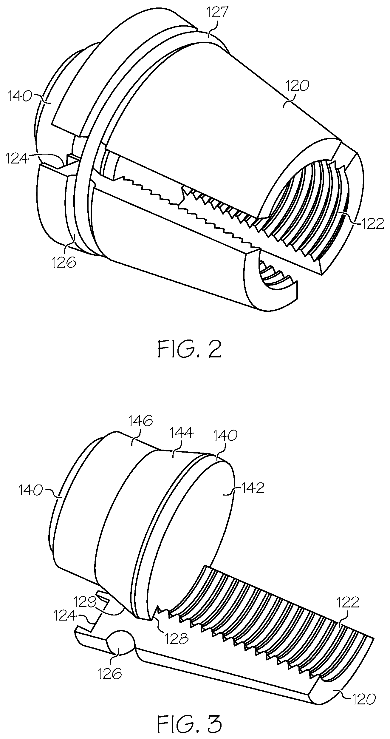
[0014] FIG. 2 is a perspective view of a sub-assembly of a plurality of locking jaws and a spacer;
[0015] FIG. 3 is another perspective view of the sub-assembly of FIG. 2 omitting all but the spacer and one of the plurality of locking jaws;
[0016] FIG. 4 is an end view illustrating a potential structure of the central section 150 shown in FIGS. 1-3.
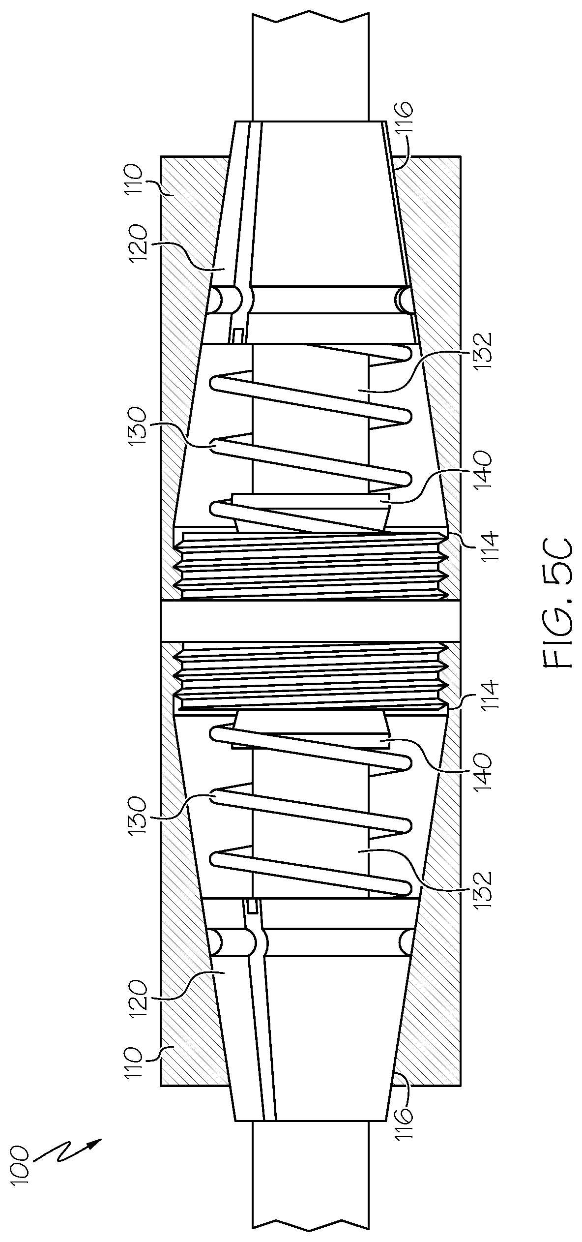
[0017] FIGS. 5A-C are side views of an installation sequence illustrating operation of the exemplary rebar coupler, with the two opposing end sections only shown in cross-section for sake of clarity.
DETAILED DESCRIPTION
[0018] Referring first to FIG. 1, an exploded side view of an exemplary rebar coupler 100 is shown. The coupler 100 has two opposing and opposite end sections 110 disposed along a central longitudinal axis L. Each end section 110 includes a frustum-shaped internal wall 112 tapering along the central longitudinal axis L from an inward position 114 to an outward position 116. As shown in FIG. 1, the wall 112 may be frusto-conical, but it will be appreciated that the wall may be frusto-pyramidal or have any other higher-order polygonal cross-section. Although a cone-shaped (frusto-conical) wall 112 may be preferred for ease of machining, a pyramidal (three or four-sided) wall or any wall with a higher-order frustum of polygonal cross section may be preferred to provide distinct guide surfaces for locking jaws. Each end section 110 also includes an assembly having plurality of locking laws 120 arrayed around the central longitudinal axis L and engaging the frustum-shaped internal wall 112. The assembly also has at least a portion of a spring 130 (as discussed in greater detail below) aligned with the central longitudinal axis L and engaging the plurality of locking jaws 120. The assembly also has a spacer 140 initially positioned within and engaging the plurality of locking jaws 120 to both radially separate the plurality of locking jaws and maintain the assembly towards the inward position 114 of the end section 110. The spacer 140 is ejectable from the plurality of locking jaws 120 through a center 132 of the spring 130 by inserting a rebar end through the outward position 116 and past the initial position of the spacer 140, whereupon the spring 130 biases the plurality of locking jaws 120 toward the outward position of the end section 110 and into full engagement with the rebar end.
[0019] As shown in FIG. 2, the plurality of locking jaws 120 may each include teeth 122 to grip the rebar end after ejection of the spacer 140. The plurality of locking jaws 120 may be manufactured from hardened or tool steel so as to "bite" into and potentially compress softer rebar material. The plurality of locking jaws 120 may collectively present a first, inwardly-open-ended spring seat 124 for receiving the spring 130. The plurality of locking jaws 120 may also collectively present a circumferential grove 126 around an inward end of the plurality of locking jaws 120. The circumferential groove 126 may hold an elastic member 127, such as an O-ring, with the diameter of the held elastic member being greater than the diameter of spring 130 so that a force applied by the spring at the spring seat 124 torques the locking jaw members about the elastic member. The diameter and relative positioning of the spring 130 and the elastic member 127 may thus bias the plurality of locking jaws 120 outward against the wall 112 of the respective end section 110 to prevent the outward ends of one or more of the jaw members from collapsing towards others. Otherwise, the elastic member 127 and the spacer 140 engaging the plurality of locking jaws 120 may bias the plurality of locking jaws 120 against the wall 112 of the end section 110 to prevent the outward ends of one or more of the jaw members from collapsing towards others.
[0020] With further reference to FIG. 3, each member of the plurality of locking jaws 120 may include a spacer seat 128 for receiving the spacer within a predetermined portion of the locking jaws. Each member of the plurality of locking jaws 120 may alternately or further include a ramped portion 129 projecting toward the central longitudinal axis L (as otherwise shown in FIG. 1). The ramped portion(s) may be disposed inward from the spacer seat(s) when both are present. Collectively the plurality of locking jaws 120 and constituent spacer seats 128 or ramped portions 129 form a socket for receiving and retaining the spacer 140, while permitting the spacer to be ejected by inserting a rebar end substantially past the initial position of the spacer.
[0021] Returning to FIG. 1, the spring 130 is illustrated as a coil compression spring but may be a wave compression spring or any other type of compression spring providing an open center 132. The spring engages the plurality of locking jaws 120 and may engage them via the inwardly-open-ended spring seat 124 described above.
[0022] As best shown in FIG. 3, the spacer 140 may include an outwardly-exposed face 142. An inserted rebar end will abut the face 142 to eject the spacer 140 into the open center 132 of the spring 130 (as otherwise shown in FIG. 1). After ejection of the spacer 140, the spring 130 biases the plurality of locking jaws 120 toward the outward position 116, toward the central longitudinal axis L along the wall 112, and into full engagement with the rebar end. When the plurality of locking jaws include spacer seats 128, the engagement of the face 142 of the spacer 140 with the spacer seats 128 may align the plurality of locking jaws 120 against the wall 112, as opposed to allowing the outward ends of one or more of the plurality of locking jaws to collapse towards others. As also shown in the figure, the spacer 140 may include a neck 144 narrowing toward the central longitudinal axis and the inward end 146 of the spacer. When the plurality of locking jaws include ramped portions 129, the engagement of the neck 144 of the spacer 140 with the ramped portions 129 may similarly align the plurality of locking jaws 120 against the wall 112, as opposed to allowing the outward ends of one or more of the plurality of locking jaws to collapse towards others. Although illustrated in combination, variants with only one of either the spacer seats 128 or the ramped portions 129, and only one of the corresponding spacer seat 128 or narrowing neck 144, are contemplated and considered useful.
[0023] Turning to FIG. 4, in a first aspect the rebar coupler 100 may include a central section 150 joining the two end sections 110 together. The central section 150 may include a backstop wall 152 or annular radial projection (not shown, but substituting for wall 152) at least partially separating cavities 154 on either side of the central section 150 along the central longitudinal axis L. The cavities 154 may provide a second spring seat 156 for the spring 130, with each assembly including a separate spring as shown in FIG. 1. When the central section 150 includes a backstop wall 152 rather than a backstop annular projection, the cavities 154 and backstop wall 152 may capture the inward end 146 of the spacer to block further movement of the spacer 140 and provide resistance against over-insertion of a rebar end. When central section 150 includes a backstop annular radial projection, the annular radial projection may capture and resist further movement of the neck 144 of spacer 140 so as to provide at least some resistance to further movement of the spacer and over-insertion of a rebar end. Either of the backstop wall 152 or annular radial projection may include an annular longitudinal projection 158 disposed between the spring seat 156 and central longitudinal axis L. The annular longitudinal projection 158 may provide a post-ejection seat for the spacer 140 when ejected from the jaw assembly 120 and separate the second spring seat 156 from the central, post-ejection seat. The central section 150 and end sections 110 of the coupler 100 may be threaded so that the sections may be joined together or include bayonet connectors or other rotatable connector features so that the sections may be joined together. Alternately, the central section 150 and end section 110 of the coupler 110 may be connected by welds or adhesives at their mutual joints so that the sections may be joined together.
[0024] In other aspects, the rebar coupler 100 may omit the central section 150, with the opposing end sections 110 abutting each other. The spring 130 in such aspects may be a single spring spanning between the respective pluralities of locking jaws 120 within the opposing end sections 110. The opposing end sections 110 of the coupler 100 may be threaded so that the sections may be joined together or include bayonet connectors or other rotatable connector features so that the sections may be joined together. Alternately, the opposing end sections 110 of the coupler 100 may be connected by welds or adhesives at their mutual joints so that the sections may be joined together.
[0025] Each end section 110 may have an aperture 118 for the insertion of a rebar end that is sized to limit the diameter of the rebar end to one equal to or less than the minimum diameter of the plurality of locking jaws 120 when the spacer 140 is in the initial position in order to allow for easy insertion of the rebar end up to the initial position. Each end section 110 and, when present, central section 150 may be manufactured (especially in thickness and material) to develop the ultimate strength of the inserted rebar across the connected rebar ends. In one example, the end sections 110 and central section 150, when present, are manufactured from carbon steel, stainless steel, carbon fiber polymer laminate, glass fiber polymer laminate (e.g., G-10), or fiber-reinforced composite. Alternately, each end section 110 may be larger in diameter than the diameter of the aperture for insertion of the rebar end so that the casing need not itself be capable of developing the specified maximum tensile strength of the inserted rebar end.
[0026] FIGS. 5A-5C depict an installation sequence showing operation of the exemplary rebar coupler. The insertion of rebar ends into the rebar coupler 100 is shown as being simultaneous for sake of clarity in description but is not necessarily required. FIG. 5A shows the rebar coupler 100 just as an inserted end of rebar begins to abut the face 142 of spacer 140, with the assembly of the plurality of locking jaws 120, the spring 130, and most particularly the spacer 140 at an initial position. Spacer 140 maintains the assembly, against the bias of spring 130, in this initial position and towards the inward position with respect to the outward position. FIG. 5B shows that continued insertion of the rebar end shifts the assembly further toward the inward position 114, permitting the plurality of locking jaws 120 to spread, increasing the bias of spring 130, and allowing the neck 144 of spacer 140 to slide along the ramped portions 129 of the plurality of locking jaws (when the latter features are present). Continued insertion of the rebar end ultimately ejects the spacer 140 from the plurality of locking jaws 120 and into the center 132 of the spring 130 whereupon, as shown in FIG. 5C, the spring biases the plurality of locking jaws toward the outward position 116 and into full engagement with the rebar end. The spacer 140 may be displaced into the central section 150, when present, and retained within the cavity 154, in engagement with the backstop wall or annular radial projection 152, annular longitudinal projection 158, or combinations thereof. Withdrawal of the rebar end will cause the plurality of locking jaws 120 to be driven by the walls 112 into the rebar end and ultimately be resisted by abutment between at least the rebar end, the adjoining plurality of locking jaws, and the adjoining casing. As suggested in the discussion of the previous paragraph, tensile loads may be carried by the casing itself to the other inserted rebar end or may be dissipated by the casing into compression of the concrete that surrounds it.
[0027] Although it may be superficially similar to the Gunin tool less "quick connect" type rebar coupler discussed in the background section above, the disclosed devices differ from that device in at least two material respects. First, as best understood by the inventors, the Gunin coupler relies upon a two-part, nested assembly of ramp and separator inserts to pre-position each set of locking jaws around the walls of a respective outward end of its coupler, where the assembly remains in contact with the jaws at all times. As a result, the assembly prevents the jaws from closing around rebar with a diameter smaller than the initial internal circumference of the set, and the coupler appears to be designed for use with a single diameter of rebar. This increases the complexity of logistics and inventory management when a project requires multiple sizes of rebar. Second, the Gunin coupler uses insertion of a rebar end to shift the jaws within the coupler and spread the jaws sufficiently to allow for the rebar end to pass between them before the jaws begin to be held in rough position by a biasing spring. As a result, the Gunin coupler will permit a rebar end to be only partially inserted, enough so that a portion of the rebar end passes between the jaws but not necessarily fully between the jaws and up to or beyond the outward end of a biasing spring, with no external visual indication that the rebar end is only partially engaged with the set of jaws. Partial engagement with the set of jaws will provide some tensile resistance to further withdrawal of the rebar end, but not full tensile resistance so as to develop the yield strength or yield and ultimate strength of the rebar. A failure to fully engage can only be tested by attempting to more fully insert the rebar end, which may not be possible when inspection is separate in time from installation and insertion, or by applying a substantial tensile force to the connection, which generally requires additional mechanical equipment. The inventors theorize that these behaviors explain why the Gunin coupler is not for use in creating ultimate strength rebar connections.
[0028] The disclosed couplers, in contrast, use a single spacer to separate each plurality of locking jaws and to pre-position that plurality of locking jaws around the walls of an inward portion of a respective opposing end section of the coupler. The single spacer is ejected from the plurality of locking jaws which may allow the plurality to close around a range of rebar sizes--from at least the initial internal circumference of the presently-described assembly down to the internal circumference at which the lateral sides of the jaw members begin to abut (i.e., somewhat smaller than that indicated in FIG. 5C)--depending upon factors such as the slope and distance between the inward and outward positions and the length of the jaws. As a result, variants of the disclosed couplers could be used to couple rebar within a range of rebar sizes, with a single device being capable e.g., of coupling #6-#10 rebar ends, while other variants may couple single sizes of rebar end or subranges of sizes of rebar ends within the customary range of sizes of #3 through #18. However, in all such devices the initial positioning of the spacer to bias/pre-position each plurality of jaws towards an inward position ensures that, with ejection of the spacer only after full insertion of the rebar end, the spring biases and shifts the plurality of locking jaws outward along the rebar end so that the locking jaws fully engage the rebar end and vice versa. As a result, the disclosed couplers could be used to develop the ultimate strength of the rebar and for use in creating ultimate strength rebar connections with a clear indication that full engagement/insertion has been achieved.
[0029] The present invention has been disclosed in detail in connection with certain preferred embodiments. There are many variations and modifications that can be made without departing from the scope of the disclosure, so that the invention is to be defined solely by the scope of the claims that follow.
* * * * *
References
D00000
D00001
D00002
D00003
D00004
D00005
D00006
XML
uspto.report is an independent third-party trademark research tool that is not affiliated, endorsed, or sponsored by the United States Patent and Trademark Office (USPTO) or any other governmental organization. The information provided by uspto.report is based on publicly available data at the time of writing and is intended for informational purposes only.
While we strive to provide accurate and up-to-date information, we do not guarantee the accuracy, completeness, reliability, or suitability of the information displayed on this site. The use of this site is at your own risk. Any reliance you place on such information is therefore strictly at your own risk.
All official trademark data, including owner information, should be verified by visiting the official USPTO website at www.uspto.gov. This site is not intended to replace professional legal advice and should not be used as a substitute for consulting with a legal professional who is knowledgeable about trademark law.