Inconel Nanotube Composite
Sullivan; Kahle B. ; et al.
U.S. patent application number 16/395804 was filed with the patent office on 2020-10-29 for inconel nanotube composite. This patent application is currently assigned to United States of America, as represented by the Secretary of the Navy. The applicant listed for this patent is Craig A. Gallmiore, Kahle B. Sullivan. Invention is credited to Craig A. Gallmiore, Kahle B. Sullivan.
| Application Number | 20200340080 16/395804 |
| Document ID | / |
| Family ID | 1000004159090 |
| Filed Date | 2020-10-29 |


| United States Patent Application | 20200340080 |
| Kind Code | A1 |
| Sullivan; Kahle B. ; et al. | October 29, 2020 |
Inconel Nanotube Composite
Abstract
A metal matrix composite (MMC) material composition of nickel alloy and carbon nanotubes is provided. The material composition includes powdered granules of the nickel alloy; and a plurality of the nanotubes. The granules and nanotubes are milled in a hopper and sintered by laser to form the MMC. A method for producing the MMC material composition is also provided. The method includes inserting powdered granules of the nickel alloy and the nanotubes into a hopper; rotating the hopper at 450 rpm for 120 min to mill the granules and the nanotubes into a mixture; and sintering said mixture by a laser at 195 W and 1100 mm/s scan speed.
| Inventors: | Sullivan; Kahle B.; (Fredericksburg, VA) ; Gallmiore; Craig A.; (Denver, CO) | ||||||||||
| Applicant: |
|
||||||||||
|---|---|---|---|---|---|---|---|---|---|---|---|
| Assignee: | United States of America, as
represented by the Secretary of the Navy Arlington VA |
||||||||||
| Family ID: | 1000004159090 | ||||||||||
| Appl. No.: | 16/395804 | ||||||||||
| Filed: | April 26, 2019 |
| Current U.S. Class: | 1/1 |
| Current CPC Class: | B22F 2201/11 20130101; B22F 3/1007 20130101; B22F 2302/403 20130101; C22C 19/055 20130101 |
| International Class: | C22C 19/05 20060101 C22C019/05; B22F 3/10 20060101 B22F003/10 |
Goverment Interests
STATEMENT OF GOVERNMENT INTEREST
[0001] The invention described was made in the performance of official duties by one or more employees of the Department of the Navy, and thus, the invention herein may be manufactured, used or licensed by or for the Government of the United States of America for governmental purposes without the payment of any royalties thereon or therefor.
Claims
1. A metal matrix composite (MMC) material composition of nickel alloy and carbon nanotubes, said material composition comprising: powdered granules of the nickel alloy; and a plurality of the nanotubes, wherein said granules and the nanotubes are milled in a hopper and sintered by a laser to form the MMC.
2. The material composition according to claim Herein the nickel alloy is Inconel 625.
3. The material composition according to claim 1, wherein the nanotubes are multi-wall carbon nanotubes (MWCNT).
4. The material composition according to claim 1, wherein the MMC is 99.5 wt % of Inconel 625 for the nickel alloy and 0.5 wt % of the nanotubes.
5. A manufacturing method for producing a metal matrix composite (MMC) material composition of nickel alloy and carbon nanotubes, said method comprising: inserting powdered granules of the nickel alloy into a hopper; inserting the nanotubes into said hopper; rotating said hopper at 450 rpm for 120 min to mill said granules and the nanotubes into a mixture; and sintering said mixture by a laser at 195 W and 1100 mm/s scan speed.
6. The manufacturing method according to claim 5, further including filtering said granules by an 80 .mu.m sieve prior to insertion into said hopper;
7. The manufacturing method according to claim 5, wherein said sintering operation is conducted within an argon (Ar) atmosphere.
Description
BACKGROUND
[0002] The invention relates generally to metal matrix composites. In particular, the invention relates to a composite of Inconel with nanotubes.
[0003] A metal matrix composite (MMC) represents a specialized set of materials composed of at least two different materials, one of which is necessarily a metal. Inconel constitutes austenitic structure nickel-chromium alloy as an oft used metal. In any composite, the physical, electrical, or thermal interaction between the constituents is critical. In order to create the composite, the two constituents must first be mixed together to form a homogenous mixture such that the secondary constituent.
[0004] Metal matrix composites have been employed in specialized applications since around the 1960's. The more traditional MMC fabrication methods, such as hot isostatic pressing (HIP), centripetal compaction, Melt infiltration, spark plasma sintering, and thermal spraying, require expensive tooling, long lead times, and complicated manufacturing to generate a useful metal matrix composite.
SUMMARY
[0005] Conventional aspirators yield disadvantages addressed by various exemplary embodiments of the present invention. In particular, exemplary embodiments provide a metal matrix composite (MMC) material composition of nickel alloy and carbon nanotubes. The material composition includes powdered granules of the nickel alloy; and a plurality of the nanotubes. The granules and nanotubes are milled in a hopper and sintered by laser to form the MMC. Further embodiments provide the nickel alloy to be Inconel 625 and the nanotubes to be
BRIEF DESCRIPTION OF THE DRAWINGS
[0006] These and various other features and aspects of various exemplary embodiments will be readily understood with reference to the following detailed description taken in conjunction with the accompanying drawings, in which like or similar numbers are used throughout, and in which:
[0007] FIG. 1 is a graphical view of Inconel particle size distribution;
[0008] FIG. 2A is a diagram view of the composite fabrication process;
[0009] FIG. 2B is a detail view of testing and analysis; and
[0010] FIG. 3 is an enlargement photographic views of the composite.
DETAILED DESCRIPTION
[0011] In the following detailed description of exemplary embodiments of the invention, reference is made to the accompanying drawings that form a part hereof, and in which is shown by way of illustration specific exemplary embodiments in which the invention may be practiced. These embodiments are described in sufficient detail to enable those skilled in the art to practice the invention. Other embodiments may be utilized, and logical, mechanical, and other changes may be made without departing from the spirit or scope of the present invention. The following detailed description is, therefore, not to be taken in a limiting sense, and the scope of the present invention is defined only by the appended claims.
[0012] The disclosure generally employs quantity units with the following abbreviations: length in microns (.mu.m) or nanometers (nm), mass in kilograms (kg), time in seconds (s) or minutes (min), area in square inches (in.sup.2), strength or torque in foot-pounds (ft-lb.sub.f), speed at millimeters-per-second (mm/s), power in watts (W), rotation in revolutions-per-minute (rpm), pressure in thousands of pounds-per-square-inch (ksi) or millions of pounds-per-square-inch (Msi), specific' surface area in square-meters-per-gram (m.sup.2/g) and density in grams-per-milliliter (g/ml equivalent to grams-per-cubic-centimeter).
[0013] Exemplary embodiments provide a 99.5% weight Inconel 625-0.5% weight multi-walled carbon nanotube (MWCNT) metal matrix composite (MMC) fabricated using direct metal laser sintering (DMLS). For exemplary embodiments, multi-wall carbon nanotubes (MWCNT), is uniformly distributed and dispersed throughout the matrix material The quality of the mixture controls the level of homogeneity and isotropic nature of material properties exhibited by the material in its useful form.
[0014] With the ramp up in additive manufacturing technology such as three-dimensional printing, specifically direct metal laser sintering (DMLS), it is now possible to bypass many of the windfalls of the more traditional methods and fabricate a useful MMC in only a short period of time, possibly even a day. The challenge to using DMLS to fabricate a metal matrix composite using MWCNT is to control the sufficient sintering (welding) of the micronized metal powder to itself and around the MWCNT while not damaging or degrading the MWCNT. DMLS employs both high temperature and laser radiation. Both of these variables, heat flow control and laser irradiance, must be intelligently handled to ensure the metal matrix composite is sufficiently processed by the machine to form a useful component, and the MWCNTs remain intact and in direct contact with the metal matrix so their material properties can be utilized.
[0015] Direct Metal Laser Sintering employs a laser with a maximum output of 400 W to selectively heat micronized metal powder of a chosen alloy such that the individual particles of metal are taken passed their liquids point to flow and combine with adjacent particles. The scanning path of the laser is determined from three dimensional computer assisted design (CAD) data that are generally "sliced" into layers with each layer being a full pass scan of the laser. Once a single layer is complete, the build platform in the DMLS machine (EOSint M280) is lowered, a new layer of powder is spread across the previously sintered layer, and the laser scanning process begins again. The current layer is sintered, or welded, to the preceding layer until all layers are complete. At this point the complete part, which has the same geometry as the CAD data, within a tolerance of the machine, can be extracted from the build plate,
[0016] The selection of the constituents of the MMC is critical. The DMLS only has fourteen different alloys to choose from such that useful parts with predictable material properties can be fabricated. This is largely a function of alloys that are produced in a micronized form by either EOS or other suppliers because the laser parameter sets on the machine are specific to the micronized powder alloy and size distribution of particles. MWCNTs were chosen as the secondary constituent largely because their outstanding material properties would cause a noticeable change in material performance, even in small weight percent of the overall composite. MWCNTs are very stable due to their SP2 electron bond structure, but are difficult to disperse and obtain a homogenous mixture due to self-attraction and van der Waal forces.
[0017] When working with MWCNT (or any carbon nanotube), dispersion is always the fundamental challenge. Inconel 625 was chosen because nickel (Ni), the base element in the alloy, does not form stable carbides over a wide and elevated temperature range. Additionally, carbon nanotubes are often grown on nickel substrates due to low reactivity between nickel and carbon. Nickel is also often used as an intermediary between MWCNT and other metals in MMCs to reduce carbide formation between the MWCNT and the metal matrix, aluminum (Al) for example, which have high affinity for carbide formation.
[0018] Any carbides formed in the MMC are a direct result of degradation, damage, or complete destruction of the MWCNT. Thus, carbide formation in MMC is usually undesirable. All details in the selection process, including the thermodynamic data, used in matrix metal selection is included in the attached technical brief. So far as known, an Inconel 625--MWCNT MMC has not been previously fabricated, especially with DMLS technology.
[0019] First, to fabricate an Inconel-MWCNT metal matrix composite using DMLS, an additive manufacturing process, where change to the material properties (yield strength, ultimate strength, elongation to failure, modulus, electrical, and thermal) can be shown to be materially altered from the base matrix alloy (Inconel 625) through test data gathered in accordance with American Society for Testing and Materials (ASTM) standards. Second, to develop or combine processes (i.e., additive manufacturing, bulk mixing methods) to circumvent complications or complexities arising in more traditional methods (HIP, casting, etc.) of MMC manufacturing.
[0020] All details on material choice and selection are given in the attached brief. As stated in the Background section, the fundamental challenge when making a MMC using MWCNT is nanotube dispersion throughout the matrix material. The MWCNT were supplied by Nanostructured & Amorphous Materials, Inc. as graphitized multi-walled carbon nanotubes, stock number 1228YJF, with the following properties: [0021] Functionalization: --OH [0022] Purity: 99.9% [0023] Content of --OH: 1.45-1.61 wt [0024] Outside Diameter: 10-20 nm [0025] Inside Diameter: 5-10 nm [0026] Length: 10-30 micrometer [0027] Specific Surface Area: >100 m.sup.2/g [0028] Color: Black The MWCNT were functionalized to aid in dispersion and graphitized to reduce impurities which would promote MWCNT damage during the rapid heating during the DMLS process.
[0029] The Inconel 625 metal matrix powder was procured through Electrical Optical Systems (EOS) GmbH of North America and is a stock product they offer for normal DMLS operation when processing Inconel 625. The tested particle size distribution and published elemental composition of the Inconel 625 is listed: [0030] Ni (nickel #28) (balance 58 wt %) [0031] Cr (chromium #24) (20-23 wt %) [0032] Mo (molybdenum #42) (8-10 wt %) [0033] Nb (niobium #41) (3.15-4.15 wt %) [0034] Fe (iron #26) (.ltoreq.0.5 wt %) [0035] Ti (titanium #22) (.ltoreq.0.4 wt %) [0036] Al (aluminum #13) (.ltoreq.0.4 wt %) [0037] Co (cobalt #27) (.ltoreq.0.1 wt %) [0038] Ta (tantalum #73) (.ltoreq.0.05 wt %) [0039] Si (tin #50), Mn (manganese #25) (each .ltoreq.0.5 wt %) [0040] P (phosphorous #15), S (sulfur #16) (each .ltoreq.0.015 wt %). The density from this alloy is a minimum of 8.4 g/ml.
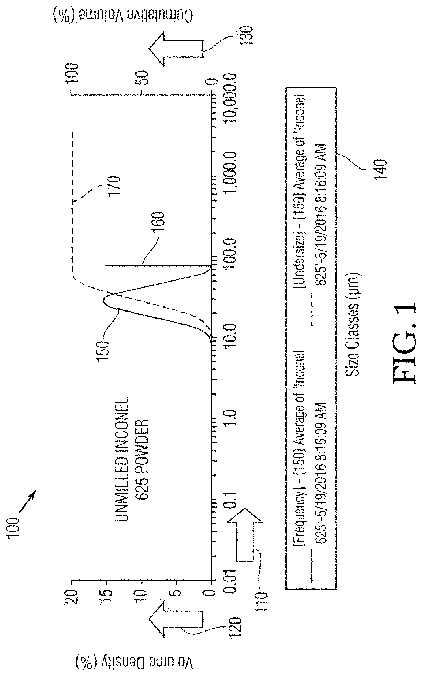
[0041] FIG. 1 shows graphical view 100 of scale plots for unmilled Inconel 625 powder. Diameter size 110 represents the abscissa in microns, while volume density 120 in percentage denotes the left ordinate and cumulative volume 130 in percent denotes the right ordinate. A legend 140 identifies a dark line for frequency and undersize components 150, with the ideal diameter 160 at 77 .mu.m for the left ordinate, and an S-curve 170 for the right ordinate.
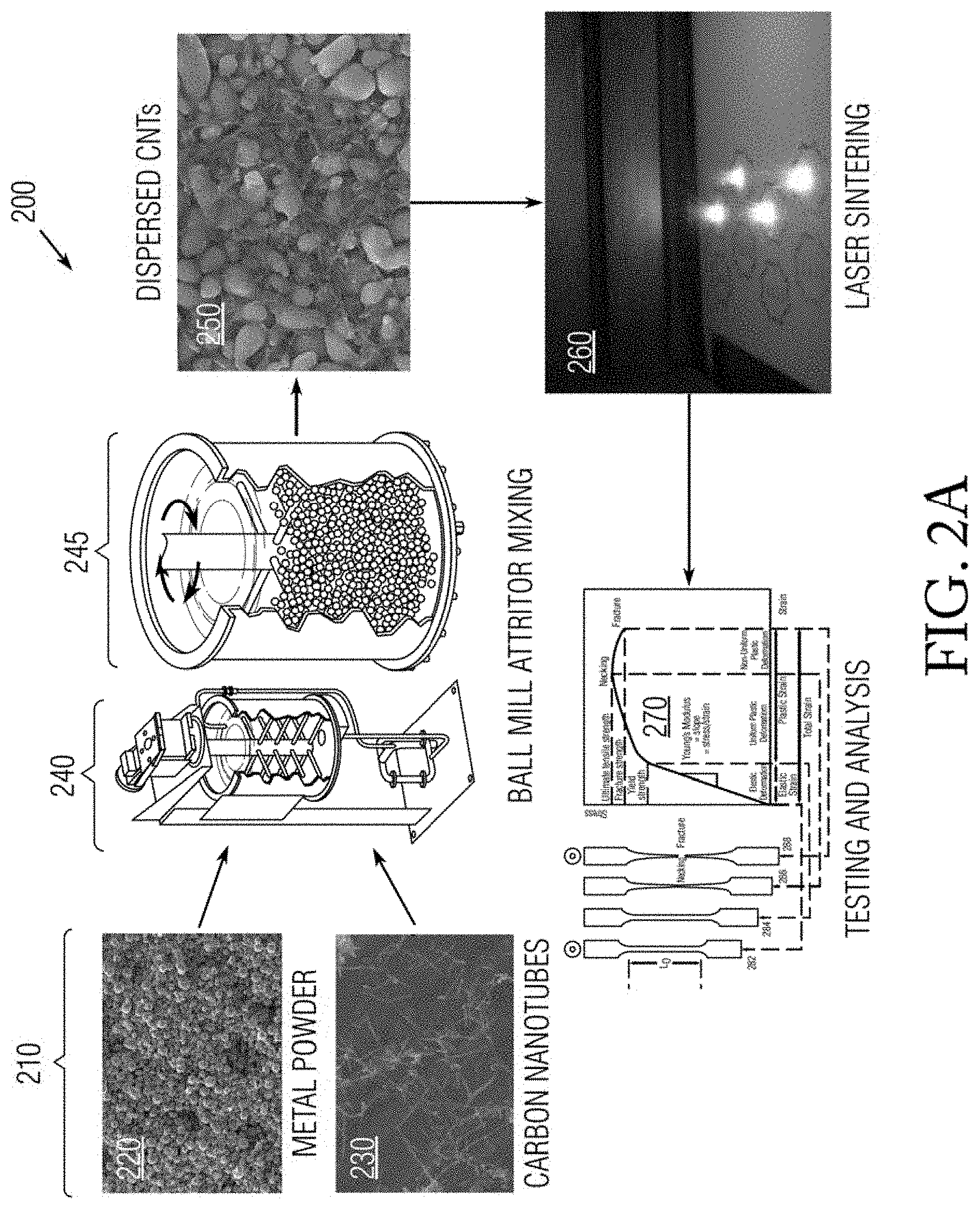
[0042] FIG. 2A shows a process flowchart 200 of MMC Manufacture using DMLS. The process begins with materials 210 that include metal powder 220 and carbon nanotubes 230 combined together in a ball mill Attritor 240 for mixing in a hopper 245. Upon completion the aggregation produces dispersed carbon nanotubes 250 subject to laser sintering 260. Following this mechanical binding process, the resulting material is subject to testing and analysis 270 with FIG. 2B providing a detail view.
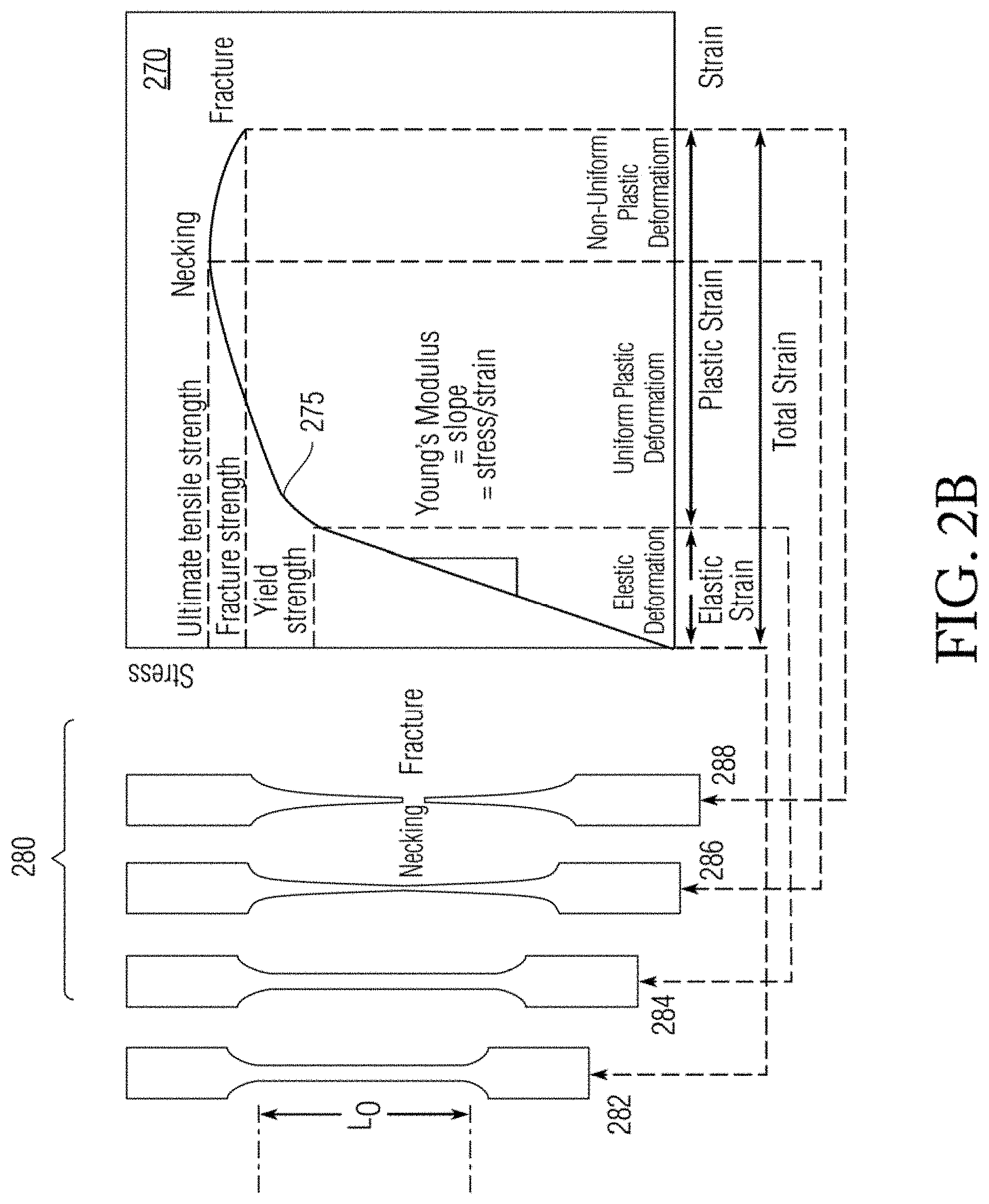
[0043] A stress-strain plot with strain (dependent response) as the abscissa and stress (driver) as the ordinate reveals a response curve 275 for metal coupons 280. Such tests are further described for ASTM E8. These coupons begin in the initial unstressed state 282, through elastic deformation 284, then plastic deformation 284 ending at necking, and finally fracture 288.
[0044] FIG. 3 shows enlargement photographic views 300 of MWCNT dispersion during milling and mixing of powder prior to sintering. The photographs show top image 310 with scale of 3 mm and, bottom image 320 with scale of 0.5 .mu.m. The top image 310 shows spheres 330 of Inconel 625. The bottom image 320 shows nanotube bundles 340.
[0045] Material Mixing is described herein for the resulting milled powder 250. The Inconel 625 powder 220 and MWCNT 230 were combined in a ball mill Attritor 240 for mechanical mixing. The relative weight percent of Inconel 625 powder 220 and MWCNT 230 were 99.5 and 0.5, respectively. The total weight of material in the Attritor 240, excluding milling media, was 30 kg. The Attritor 240 used 440C stainless steel milling media with a Rockwell hardness of 58-65to agitate and disperse the MWCNT 230 into the Inconel 625 powder 220. The material and hardness (treatment) of the media were chosen to reduce cross contamination between the milling media and Inconel 625 powder 220. The hopper 245 spun at 450 rpm for 120 min to adequately disperse the MWCNT 230.
[0046] Laboratory experiments 270 were conducted to determine an adequate milling time such that good MWCNT dispersion was evident and changes in particle size distribution of Inconel 625 was kept to a minimum. A small addition of two weight percent (2 wt %) deionized water (H.sub.2O) was added to the mixture as a process control agent prior to milling to inhibit cold welding of the Inconel 625 particles when caught in between the stainless steel milling media. This was an effort to reduce the change in particle size distribution of the Inconel 625 powder 220 prior to direct metal laser sintering 260.
[0047] Direct metal laser sintering 260 is described herein. The milled powder 250 was fed through an 80 micron (or .mu.m) sieve into the powder distribution hopper 245 of the EOS M280 DMLS machine 240 to eliminate or filter particles that had grown too large (due to cold welding) during the mixing process. The layer thickness of the DMLS was set to 20 .mu.m and a high speed steel recoating blade was used to distribute powder over the build plate. The sample geometries were oversized versions of ASTM-E8M and ASTM-E23 test specimens such that they could be post machined to final size prior to testing.
[0048] The laser operated at 195 W and 1100 mm/s scan speed. These parameters were chosen to ensure the MWCNT could handle the DMLS laser irradiance based on prior research into laser calorimetry. The sintering process took place in a 99.9% industrial grade argon (Ar) atmosphere to reduce oxidation of any material.
[0049] AU parts were built on a hybrid support structure to optimize heat transfer from the test specimens and the build plate and reduce residual stresses in completed parts. The hybrid support structure comprised solid Inconel 625 support at each end with an approximate area of 0.25 in.sup.2 (per end) with latticed support throughout the middle of each specimen. The specimens were then cut free of the build plate and post machined to applicable ASTM test geometry after the build was complete.
[0050] Testing performed 270 is described as follows. The specimens were tested to ASTM-E8M and ASTM-E23 to record relevant test data. Test data (yield strength, ultimate tensile strength, elongation to failure (%), elastic modulus, percent shear fracture, and Charpy impact strength) was collected and post-processed, and compared against 100 wt % Inconel 625 specimens fabricated in the same manner as the MMC specimens. Scanning Electron Micrographs were taken of the materials to prove MWCNT survival.
[0051] Results are presented as follows. The MMC specimens showed the following average increase/(decrease) in material properties over the 100 wt % Inconel 625 specimens. [0052] Yield Strength: 34.5% (144.1 ksi versus 107.1 ksi) [0053] Ultimate Tensile Strength: 26.8% (187 ksi versus 147.5 ksi) [0054] Elongation to failure: (58.5%) (15.7% versus 37.8%) [0055] Elastic Modulus: 5.9% (28.5 Msi versus 26.9 Msi) [0056] Resilience: 57.8% (710 in-lb.sub.f/in.sup.3 versus 450 in-lb.sub.f/in.sup.3) [0057] Charpy Impact Strength: (74.7%) (26.2 ft-lb.sub.f versus 103.6 ft-lb.sub.f) [0058] Hardness: 19.9% (30.7 RHC versus 25.6 RHC) Note that resilience is area under the stress-strain curve from zero load to yield.
[0059] As can be observed, the MMC possesses higher values over the pure Inconel 625 in yield strength, ultimate tensile strength, elastic modulus, resilience, and hardness, along with less elongation to failure. Charpy impact strength is constitutes the primary tradeoff.
[0060] Commercial Potential can be introduced as follows. As stated in the background section, MMCs have been employed in high performance applications for about the last half century. However, the ability to fabricate MMCs using Direct Metal Laser Sintering affords significant time and cost savings over more traditional methods of MMC manufacture. DMLS circumvents the necessity for mold design, mold fabrication, and mold reconditions, which are required in MMC fabrication using HIP, for example.
[0061] Multiple components can be fabricated at the same time using DMLS with little machine oversight. Additionally, many MMCs are not 100% solid. Due to traditional manufacture, with the exception of melt infiltration or melt casting of MMC, which are very expensive, there are often voids which create stress concentrations in the material causing premature or unpredictable failure. DMLS processing produces a 100% solid part with predictable material properties and dynamics under load.
[0062] Purpose for the exemplary embodiments are described herein. In the 30-year Department of the Navy (DON) Research and Development (R&D) plan, there is emphasis on developing processes and technology to further additive manufacturing and nanotechnology. The primary objective for these efforts is to utilize additive manufacturing processes to produce production representative hardware.
[0063] Up until recently, most additive manufacturing efforts have been geared towards making prototypes quickly (rapid prototyping) for design verification rather than deployment. MMCs are typically used in applications where a combination of material properties from each constituent is desired (thermal and strength, electrical and ductility, etc). Utilizing DMLS to fabricate MMCs with known material properties (through testing) is a large step towards producing parts composed of advanced materials which can satisfy a Navy need in a very short period of time compared to historic MMC development.
[0064] The advantages of exemplary embodiments include: Using DMLS to fabricate MMCs creates significant time and cost savings, where much of the design normally used to construct molds or fine tune expensive and lengthy processes can now be circumvented. MMCs that would traditionally take weeks or even months to fabricate can now be made in as little as a day if all the equipment and material is readily available. The MMC parts made with DMLS are also 100% solid and have predictable and repeatable material properties and load characteristics so long as the parts with that material formulation have been previously tested.
[0065] Alternatives to the exemplary embodiments possess distinct disadvantages. Refinements to the powder mixing process to achieve better dispersion of MWCNT (or other nanorod, nanotube, or nanopowder) would be a critical improvement to the process. This author believes (through research) that employing a large sonic acoustic resonant mixing machine with a higher content of deionized water as a process control agent (PCA) and resonant frequency of >60 Hz would create enough shear energy and lubrication to disperse the secondary constituent into the metal powder. This process also alleviates the concern of MWCNT damage and cold welding of the metal particles due to collision of milling media.
[0066] This mixing process requires an inert, preferably argon (Ar), atmosphere to reduce reactivity. Upon mixing completion, the powder mixture can be dried in an oven (also inert) at an intermediate temperature to evaporate any left over PCA. Another possible alternative to producing a homogenously mixed powder would be to incorporate the nanoparticle or nanotube into the powder manufacturing, process. Chemical vapor deposition (CVD) or introduction of a secondary constituent into the powder micronization process encapsulates the secondary constituent into the inner volume of metal particles and create a more homogenous mixture. Alternatives to the DMLS process would be selective laser sintering (SLS) or spark plasma sintering (SPS) without much practical distinction.
[0067] While certain features of the embodiments of the invention have been illustrated as described herein, many modifications, substitutions, changes and equivalents will now occur to those skilled in the art. It is, therefore, to be understood that the appended claims are intended to cover all such modifications and changes as fall within the true spirit of the embodiments.
* * * * *
D00000
D00001
D00002
D00003
D00004
XML
uspto.report is an independent third-party trademark research tool that is not affiliated, endorsed, or sponsored by the United States Patent and Trademark Office (USPTO) or any other governmental organization. The information provided by uspto.report is based on publicly available data at the time of writing and is intended for informational purposes only.
While we strive to provide accurate and up-to-date information, we do not guarantee the accuracy, completeness, reliability, or suitability of the information displayed on this site. The use of this site is at your own risk. Any reliance you place on such information is therefore strictly at your own risk.
All official trademark data, including owner information, should be verified by visiting the official USPTO website at www.uspto.gov. This site is not intended to replace professional legal advice and should not be used as a substitute for consulting with a legal professional who is knowledgeable about trademark law.