Selectively Openable Closure for a Container
French; Jordan Robert ; et al.
U.S. patent application number 16/855743 was filed with the patent office on 2020-10-29 for selectively openable closure for a container. This patent application is currently assigned to Berry Global, Inc.. The applicant listed for this patent is Berry Global, Inc.. Invention is credited to Jordan Robert French, Steven Daniel Gift, Seth A. Tempel, John A. Vassallo.
| Application Number | 20200339323 16/855743 |
| Document ID | / |
| Family ID | 1000004823863 |
| Filed Date | 2020-10-29 |


View All Diagrams
| United States Patent Application | 20200339323 |
| Kind Code | A1 |
| French; Jordan Robert ; et al. | October 29, 2020 |
Selectively Openable Closure for a Container
Abstract
A closure for a container, and more specifically a closure that is selectively openable and/or lockable providing, for example, one or more child resistant opening features is disclosed.
| Inventors: | French; Jordan Robert; (Evansville, IN) ; Tempel; Seth A.; (Evansville, IN) ; Vassallo; John A.; (Lititz, PA) ; Gift; Steven Daniel; (Lititz, PA) | ||||||||||
| Applicant: |
|
||||||||||
|---|---|---|---|---|---|---|---|---|---|---|---|
| Assignee: | Berry Global, Inc. Evansville IN |
||||||||||
| Family ID: | 1000004823863 | ||||||||||
| Appl. No.: | 16/855743 | ||||||||||
| Filed: | April 22, 2020 |
Related U.S. Patent Documents
| Application Number | Filing Date | Patent Number | ||
|---|---|---|---|---|
| 62837327 | Apr 23, 2019 | |||
| Current U.S. Class: | 1/1 |
| Current CPC Class: | B65D 2251/0078 20130101; B65D 50/06 20130101; B65D 2251/0021 20130101; B65D 51/18 20130101; B65D 41/04 20130101 |
| International Class: | B65D 51/18 20060101 B65D051/18; B65D 41/04 20060101 B65D041/04; B65D 50/06 20060101 B65D050/06 |
Claims
1. A package, comprising: a container defining a product storage region; and a closure coupled to the container and having an opening in the closure that is in communication with the product storage region to allow contents of the product storage region to be dispensed through the closure opening; wherein the closure includes a lid and a base, wherein the lid is selectively openable and closeable relative to the base by a first user input; and a tab coupled to the base and having a tab attachment portion that forms a locked position with a lid locking protrusion coupled to the lid; wherein the tab includes a pair of tab stems defining a tab aperture disposed between the tab stems, and the tab aperture is configured to receive the lid locking protrusion when the closure is in the closed and locked positions; wherein the tab attachment portion is movable by a second user input from the locked position to an unlocked position in which the lid is movable from a closed position to an open position relative to the base; and wherein the tab attachment portion is moved from the locked position to the unlocked position by deflecting the tab stems, and the tab stems are biased toward the locked position from the unlocked position.
2. The package of claim 1, wherein the lid is coupled to the base by a hinge that allows rotational movement of the lid relative to the base.
3. The package of claim 1, wherein the lid locking protrusion is disposed between a first bumper and a second bumper.
4. The package of claim 1, wherein at least one lip extends in a vertical direction on at least one side of the tab.
5. The package of claim 4, including a first lip and a second lip that are flush with an outer circumference of the closure base, extend in the vertical direction, and are disposed on opposite sides of the tab.
6. The package of claim 5, wherein the first lip and second lip extend upwardly from the base.
7. The package of claim 6, wherein the first lip partially blocks the first bumper when in the closed position.
8. The package of claim 7, wherein the second lip partially blocks the second bumper when in the closed position.
9. The package of claim 1, further comprising a plurality of ribs adjacent the closure opening.
10. The package of claim 9, wherein the plurality of ribs is configured to funnel a pill away from the closure skirt and toward the closure opening.
11. A closure, comprising: a lid and a base, wherein the lid is selectively openable and closeable relative to the base by a first user input; an opening in the base that is configured to allow contents of a container to be dispensed through the opening; and a tab coupled to the base and having a tab attachment portion that forms a locked position with a lid locking protrusion coupled to the lid; wherein the tab includes a pair of tab stems defining a tab aperture disposed between the tab stems, and the tab aperture is configured to receive the lid locking protrusion when the closure is in the closed and locked positions; wherein the tab attachment portion is movable by a second user input from the locked position to an unlocked position in which the lid is movable from a closed position to an open position relative to the base; and wherein the tab attachment portion is moved from the locked position to the unlocked position by deflecting the tab stems, and the tab stems are biased toward the locked position from the unlocked position.
12. The closure of claim 11, wherein the lid is coupled to the base by a hinge that allows rotational movement of the lid relative to the base.
13. The closure of claim 11, wherein the lid locking protrusion is disposed between a first bumper and a second bumper.
14. The closure of claim 11, wherein at least one lip extends in a vertical direction on at least one side of the tab.
15. The closure of claim 14, including a first lip and a second lip that are flush with an outer circumference of the closure base, extend in the vertical direction, and are disposed on opposite sides of the tab.
16. The closure of claim 15, wherein the first lip and second lip extend upwardly from the base.
17. The closure of claim 16, wherein the first lip partially blocks the first bumper when in the closed position.
18. The closure of claim 17, wherein the second lip partially blocks the second bumper when in the closed position.
19. The closure of claim 11, further comprising a plurality of ribs adjacent the closure opening, wherein the plurality of ribs is configured to funnel a pill away from the closure skirt and toward the closure opening.
20. A package, comprising: a container defining a product storage region; and a closure coupled to the container and having an opening in the closure that is in communication with the product storage region to allow contents of the product storage region to be dispensed through the closure opening; wherein the closure includes a lid and a base, wherein the lid is selectively openable and closeable relative to the base by a first user input; and a tab coupled to the base and having a tab attachment portion that forms a locked position with a lid locking protrusion coupled to the lid; wherein the tab attachment portion is movable by a second user input from the locked position to an unlocked position in which the lid is movable from a closed position to an open position relative to the base; and wherein the tab attachment portion is moved from the locked position to the unlocked position by deflecting the tab, and the tab is biased toward the locked position from the unlocked position.
Description
PRIORITY CLAIM
[0001] This application claims priority under 35 U.S.C. .sctn. 119(e) to U.S. Provisional Application Ser. No. 62/837,327 filed Apr. 23, 2019, which is expressly incorporated by reference herein.
TECHNICAL FIELD
[0002] The present disclosure relates generally to a closure for a container, and more specifically to a closure that is selectively openable and/or lockable providing, for example, one or more child resistant opening features.
BACKGROUND
[0003] It is often desirable to make a container selectively openable by providing a closure for the container. For example, the closure may be selectively opened and closed and may include a locking or blocking feature that makes it more difficult or resistant to opening by a child.
SUMMARY
[0004] Certain embodiments according to the present disclosure provide a selectively openable closure for a container. Some embodiments may provide a closure that is resistant to opening by including two separate motions or user inputs to open, for example.
[0005] In one aspect, for instance, a package may be provided, comprising a container defining a product storage region. A closure may be coupled to the container and have an opening in the closure that is in communication with the product storage region to allow contents of the product storage region to be dispensed through the closure opening. The closure may include a lid and a base. The lid may be selectively openable and closeable relative to the base by a first user input. A tab may be coupled to the base and having a tab attachment portion that forms a locked position with a lid locking protrusion coupled to the lid. The tab may include a pair of tab stems defining a tab aperture disposed between the tab stems, and the tab aperture is configured to receive the lid locking protrusion when the closure is in the closed and locked positions. The tab attachment portion may be movable by a second user input from the locked position to an unlocked position in which the lid is movable from a closed position to an open position relative to the base. The tab attachment portion may be moved from the locked position to the unlocked position by deflecting the tab stems, and the tab stems are biased toward the locked position from the unlocked position.
[0006] In another aspect, for instance, a closure may be provided, comprising a lid and a base. The lid may be selectively openable and closeable relative to the base by a first user input. an opening in the base may be configured to allow contents of a container to be dispensed through the opening. A tab may be coupled to the base and having a tab attachment portion that forms a locked position with a lid locking protrusion coupled to the lid. The tab may include a pair of tab stems defining a tab aperture disposed between the tab stems, and the tab aperture is configured to receive the lid locking protrusion when the closure is in the closed and locked positions. The tab attachment portion may be movable by a second user input from the locked position to an unlocked position in which the lid is movable from a closed position to an open position relative to the base. The tab attachment portion may be moved from the locked position to the unlocked position by deflecting the tab stems, and the tab stems are biased toward the locked position from the unlocked position.
[0007] In yet another aspect, for instance, a package is provided, comprising a container defining a product storage region. A closure may be coupled to the container and having an opening in the closure that is in communication with the product storage region to allow contents of the product storage region to be dispensed through the closure opening. The closure may include a lid and a base, wherein the lid is selectively openable and closeable relative to the base by a first user input. A tab may be coupled to the base and having a tab attachment portion that forms a locked position with a lid locking protrusion coupled to the lid. The tab attachment portion may be movable by a second user input from the locked position to an unlocked position in which the lid is movable from a closed position to an open position relative to the base. The tab attachment portion may be moved from the locked position to the unlocked position by deflecting the tab, and the tab is biased toward the locked position from the unlocked position.
BRIEF DESCRIPTION OF THE DRAWINGS
[0008] The detailed description particularly refers to the accompanying figures, in which:
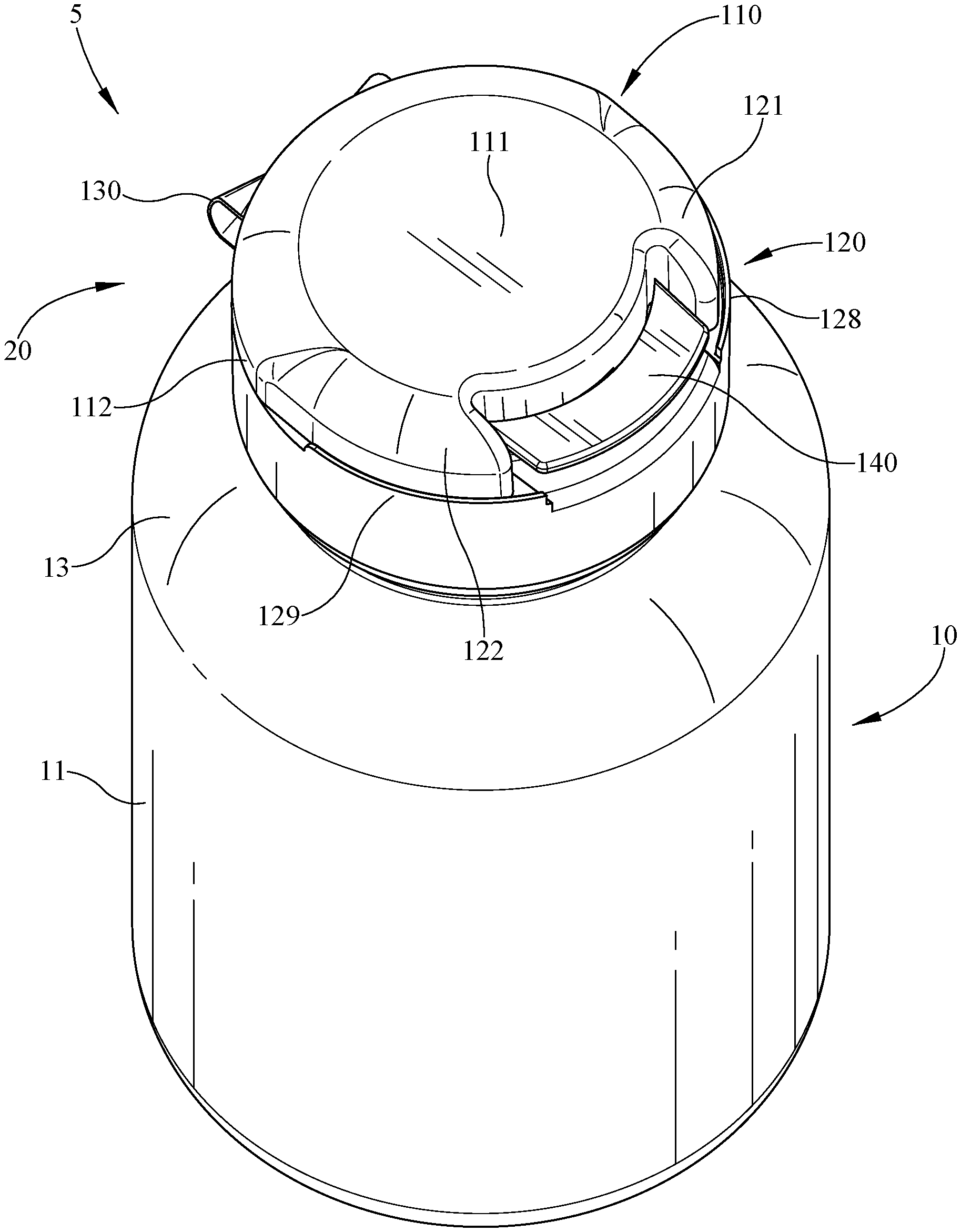
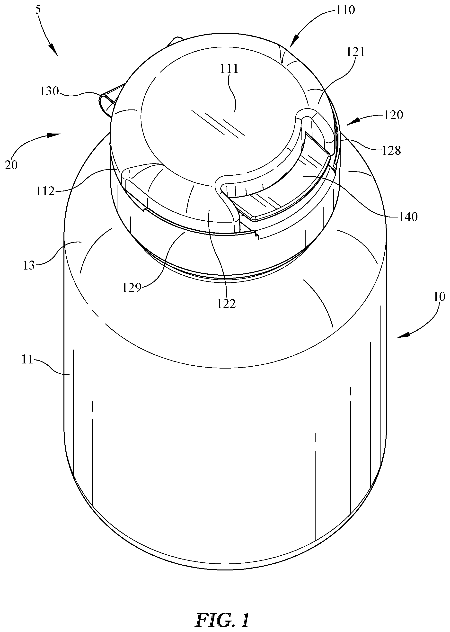
[0009] FIG. 1 illustrates a perspective view of an exemplary embodiment of a package that includes a container and a child-resistant closure in a closed position;
[0010] FIG. 2 illustrates a front view of the package of FIG. 1;
[0011] FIG. 3 illustrates a first side view of the package of FIG. 1;
[0012] FIG. 4 illustrates a top view of the package of FIG. 1;
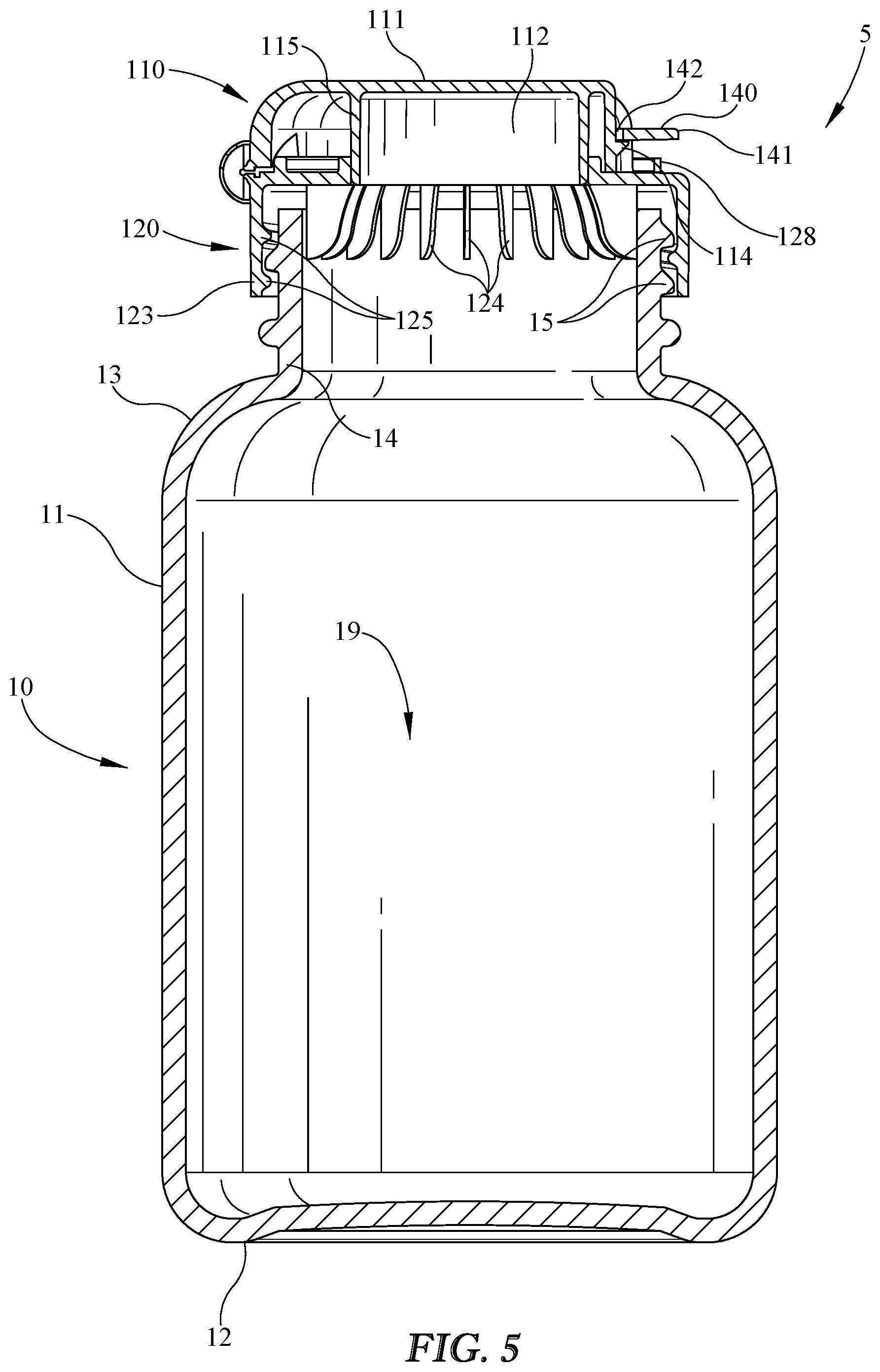
[0013] FIG. 5 illustrates a first side cross-section view of the package of FIG. 1;
[0014] FIG. 6 illustrates a second side cross-section view of the closure of FIG. 5;
[0015] FIG. 7 illustrates a top perspective cross-section view of the closure of FIG. 6;
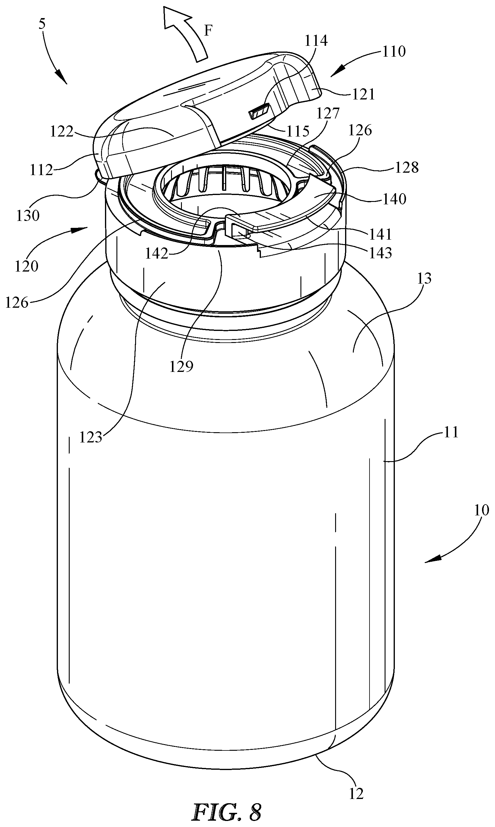
[0016] FIG. 8 illustrates a top perspective view of the package of FIG. 1, shown in an open position;
[0017] FIG. 9 illustrates a front perspective view of an embodiment of a closure in an open position;
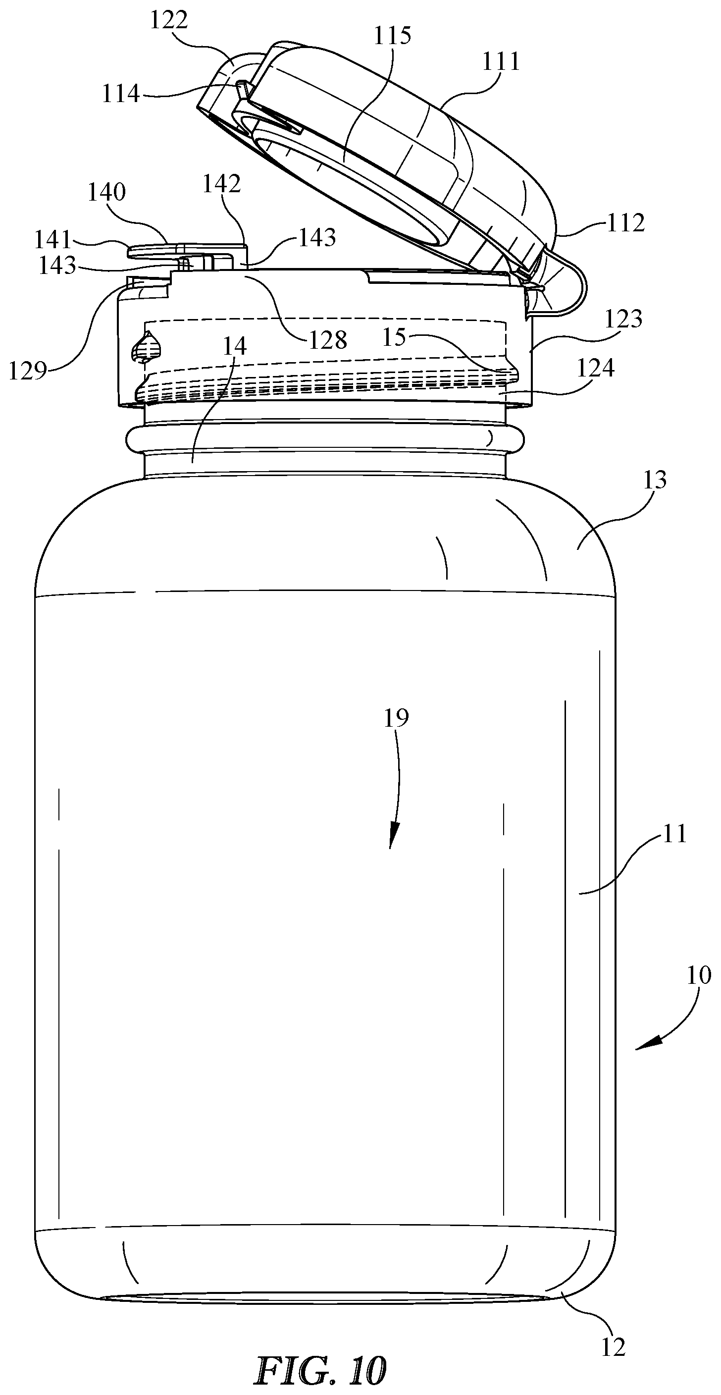
[0018] FIG. 10 illustrates a front perspective view of the package of FIG. 8 in an open position, with the closure shown in partial transparency to illustrate an exemplary attachment mechanism using threaded engagement between the closure and a container;
[0019] FIG. 11 illustrates a second side view of the package of FIG. 1;
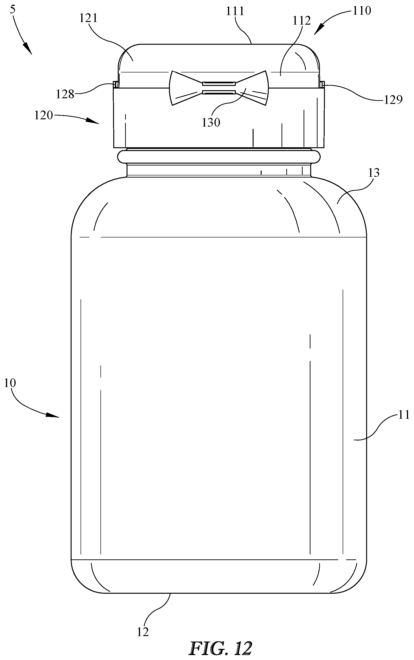
[0020] FIG. 12 illustrates a back view of the package of FIG. 1;
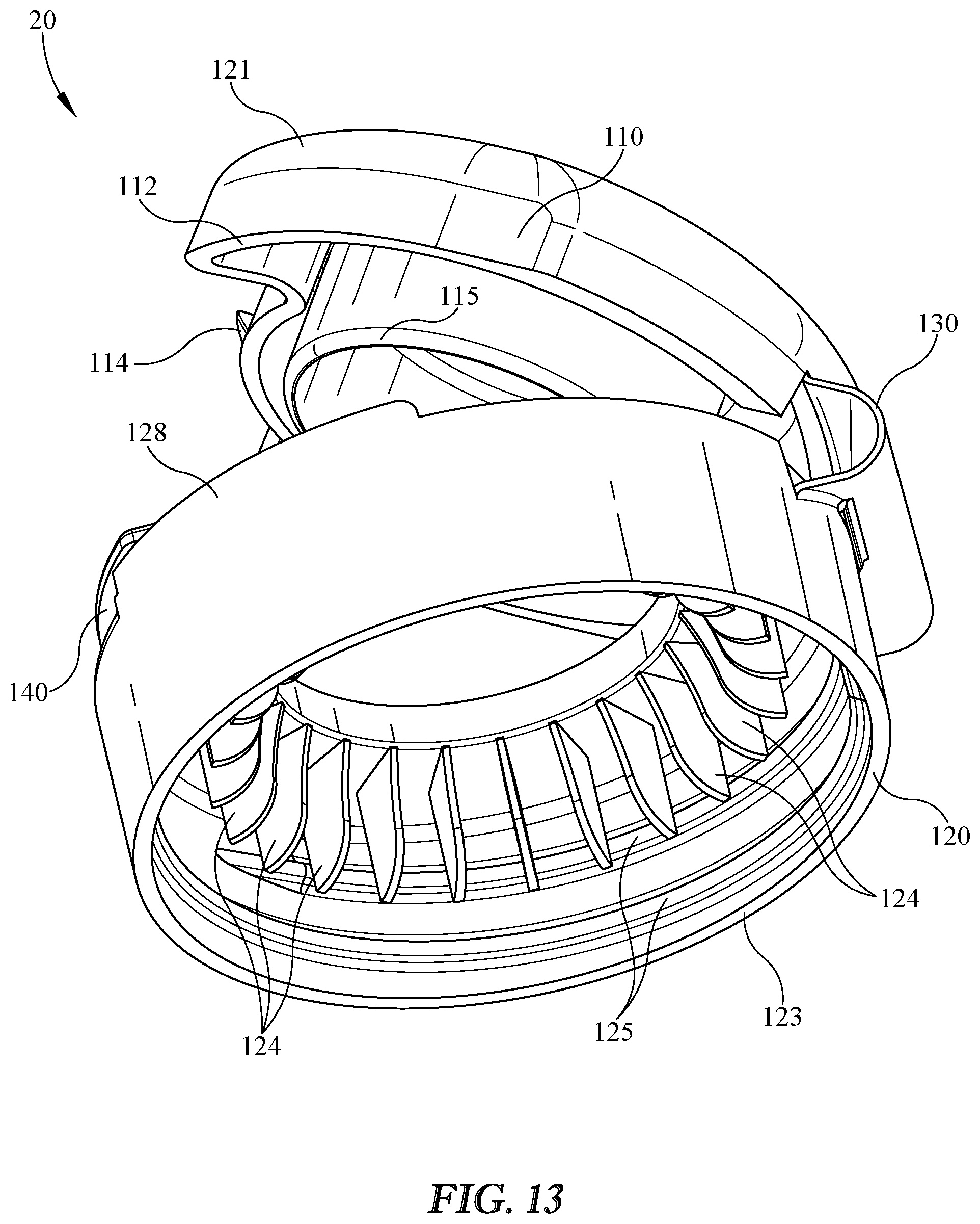
[0021] FIG. 13 illustrates a bottom perspective view of the closure of FIG. 9;
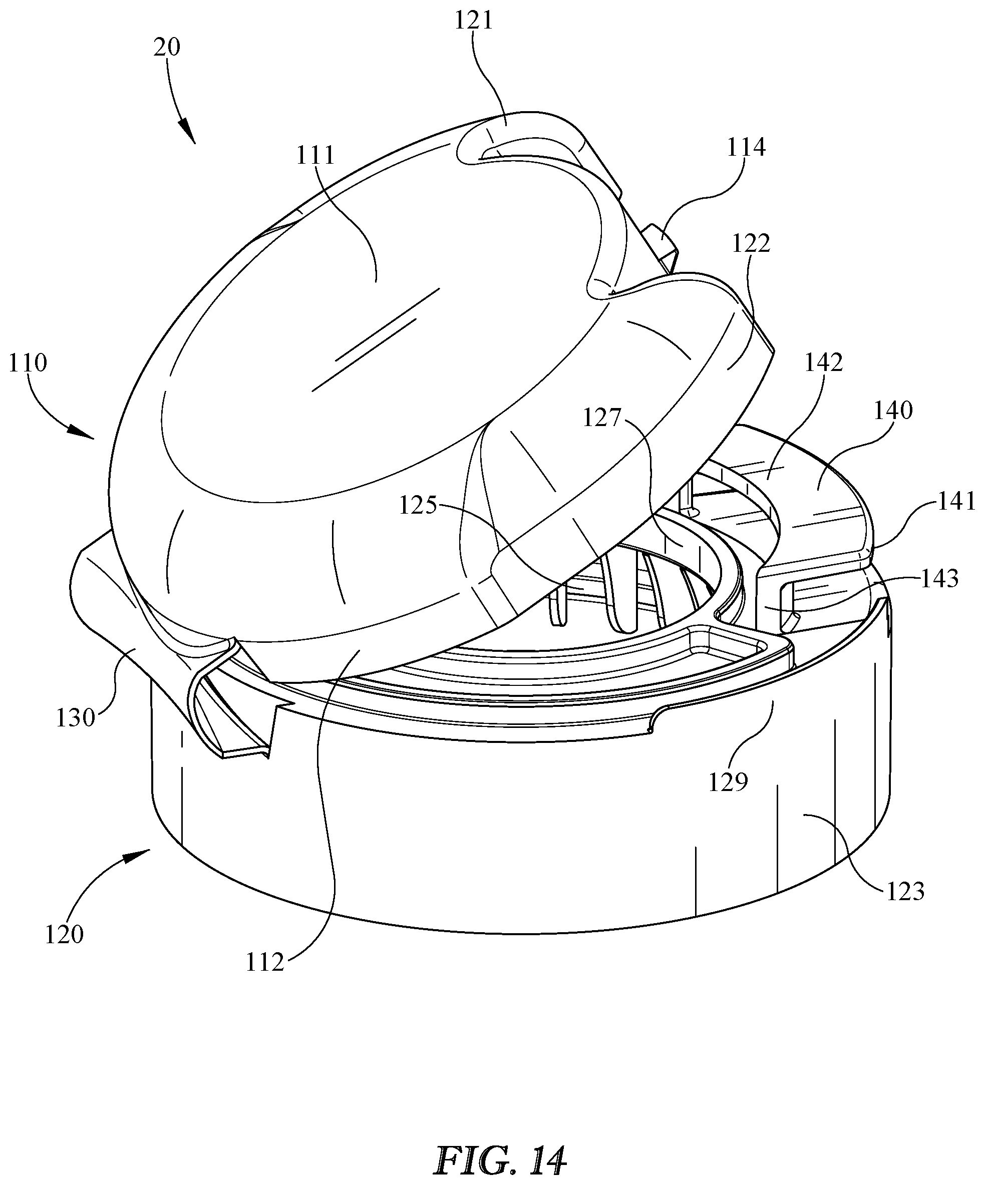
[0022] FIG. 14 Illustrates a top perspective view of the closure of FIG. 9;
[0023] FIG. 15 illustrates another top perspective view of the closure of FIG. 9; and
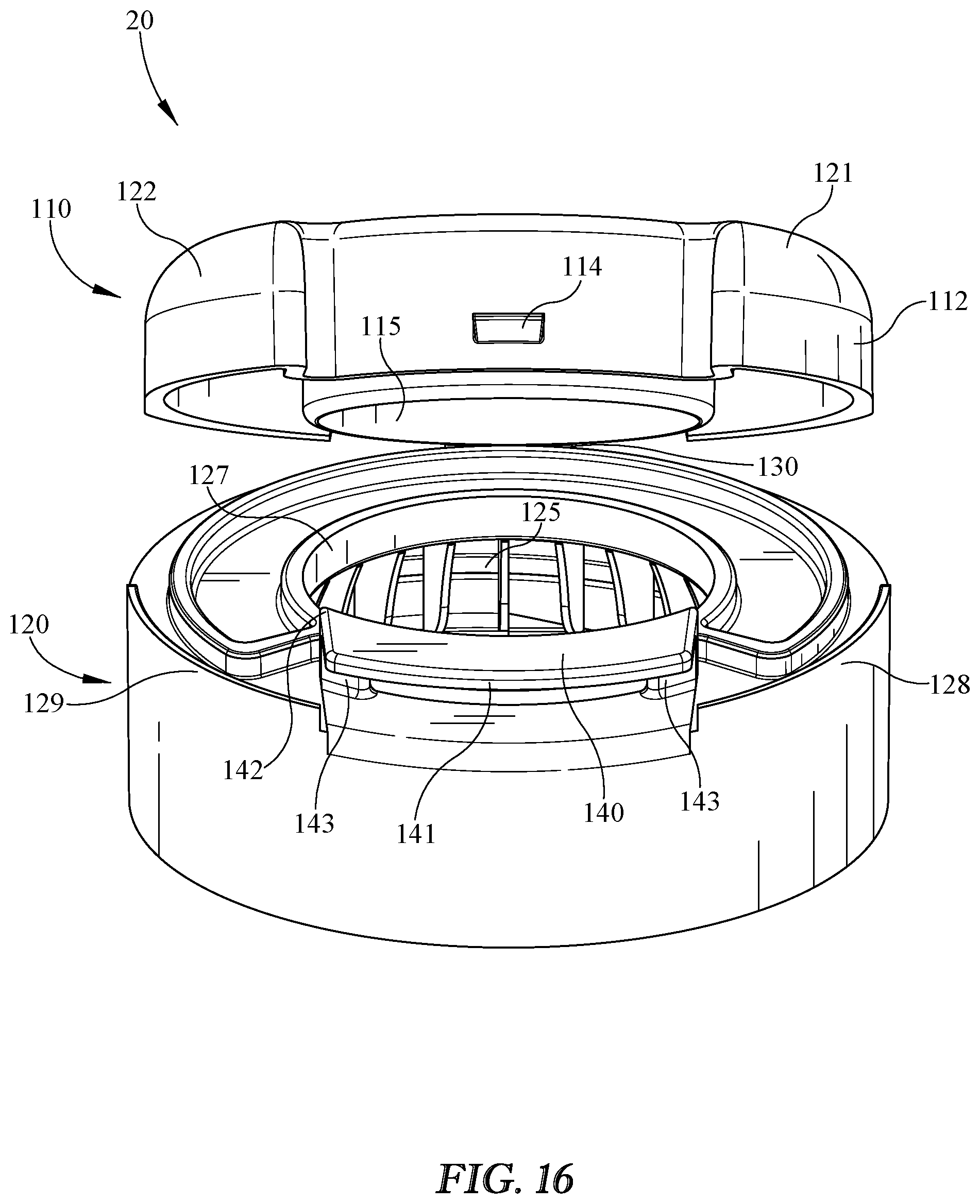
[0024] FIG. 16 illustrates a front perspective view of the closure of FIG. 9.
DETAILED DESCRIPTION
[0025] Embodiments now will be described more fully hereinafter with reference to the accompanying drawings, in which some, but not all embodiments are shown. As used in the specification, and in the appended claims, the singular forms "a", "an", "the", include plural referents unless the context clearly dictates otherwise.
[0026] The terms "substantial" or "substantially" may encompass the whole as specified, according to certain embodiments, or largely but not the whole specified according to other embodiments.
[0027] Some embodiments of a package 5 such as shown in FIG. 1 may include a container or bottle 10 and/or a closure 20. If included, container 10 may include a side wall 11, a floor 12, and/or a shoulder 13, any or all of which may substantially define a product storage region 19 in container 10 (see, e.g., FIG. 5). Package 5 is shown in FIG. 1 in an exemplary closed position with closure 20 attached, coupled, and/or fastened to container 10. For example, closure 20 may snap on or screw on to container 10. Closure 20 may be configured so that a user may selectively open or remove closure 20 from container 10 to provide package 5 in an open position so that, for example, the user may access contents of container 10 and/or package 5. Closure 20 may be provided such that a user may selectively reclose container 10 and/or package 5 by reclosing, reconnecting, or reattaching closure 20 to container 10.
[0028] Closure 20 may include a lid 110 that is selectively openable relative to a closure base 120 by one or more user inputs, and/or selectively closeable relative to closure base to provide the closed and/or locked position shown in FIGS. 1-7. For example, a user may provide an opening input and/or open lid 110 relative to base 120 by rotating lid 110 upwardly relative to base 120 about a hinge 130. To prevent or inhibit unwanted opening of lid 110, for example, or for any other reason or for any combination thereof, package 5 and/or closure 20 may include a locking mechanism such as a mechanical stop formed between a portion of lid 110 and a tab 140. Tab 140 may include a feature that prevents upward movement or rotation of lid 110 relative to tab 140, for example, until a user actuates and/or moves tab 140 out of blocking engagement and/or from a locked position to an unlocked position. Closure 20 and/or base 120 may include one or more lips, such as first lip 128 and/or second lip 129 for any of a variety of reasons, including, but not limited to, providing additional security and/or protection of the closure around tab 140, and/or for aesthetic purposes. If included, either or both of lips 128, 129 may extend upwardly from base 120. Alternatively, either or both lips 128, 129 could extend downwardly from lid 110, or one lip 128 or 129 could extend upwardly from base 120 while the other lip 129 or 128 could extend downwardly from lid 110, for example.
[0029] Lid 110 may include a cover 111 and/or a lid skirt 112 that prevent, inhibit, and/or block access to product storage region 19 when in the closed position shown in FIGS. 1-7. Base 120 may include a first bumper 121 and/or a second bumper 122 for any of a variety of reasons, including, but not limited to, protecting tab 140 and/or preventing or inhibiting accidental actuation of tab 140, providing a structure with a more gradual transition of outer diameter or perimeter or height to that of tab 140, and/or to provide a more pleasing aesthetic. Package 5 may be configured so that a user can hold container 10 in one hand, provide a first input by pushing, pulling, or moving tab 140 radially outwardly relative to lid 110 and/or base 120 to unlock or unblock lid 110 from upward movement or rotation, and provide a second input by pushing, pulling, moving, or rotating lid 110 from the closed position to the open position, for example, by pushing or pulling upwardly on lid 110 to cause rotation of lid 110 about hinge 130.
[0030] FIGS. 5-7 show package 5, closure 20, and/or components thereof in a closed position and in cross-section to illustrate additional features. For example, closure 20 may couple, connect, and/or attach to container 10 by an attachment mechanism such as a permanent or semi-permanent attachment. For example, closure 20 may have a lip, bead, or protrusion engaged to snap fit with a corresponding, lip, bead, or protrusion of container 10. The threaded engagement between neck threads 15 on container neck 14 and base threads 125 on closure base 120 are shown as an example of an alternative attachment mechanism. Other attachment mechanisms may be included instead of or in addition to snap fit and/or threaded engagement, such as friction fit and/or integral formation of closure 20 and container 10, for example. Base 120 of closure 20 may include an outer skirt 123 and/or one or more ribs 124 for any of a variety of reasons. For example, ribs 124 may include one or more features that facilitate attachment or coupling to container 10, and/or outer skirt 123 may provide a more gradual transition of closure 20 to container 10, may protect radially inward features, and/or may provide a more pleasing aesthetic.
[0031] Lid 110 may open from an end or area opposite hinge 130, for example, diametrically opposed hinge 130, to facilitate opening of lid 110 relative to base 120, or for any other reason or combination of reasons. Lid 110 may include a lid locking protrusion 114 at or near the end or area opposite hinge 130, and/or locking protrusion 114 may project in a radial direction and/or be configured to form a mechanical stop with a corresponding feature of tab 140, such as a tab attachment portion 142 that may include, for example, a tab aperture, tab protrusion, and/or inward edge. While in the closed position and in a resting state, tab attachment portion 142 may radially overlap and/or extend radially inwardly over lid locking protrusion 114, and/or be provided in a locked position such that tab attachment portion 142 inhibits or prevents upward movement of lid locking protrusion 114 relative to tab attachment portion 142 and consequently inhibits or prevents lid 110 from rotating or moving to an open position relative to base 120. Tab 140 may be coupled, attached, and/or integrally formed with base 120 to facilitate locking of lid 110 in the closed position. Tab 140 may be coupled or attached to base 120, and/or integrally formed therewith, for example, by one or more tab stems 143, which may extend downwardly from tab 140 and/or be disposed radially between tab attachment portion 142 and a tab outer tip 141. A tab aperture may be formed between tab stems 143, which may form and/or be included in tab attachment portion 142, for example, by providing a location for insertion of lid locking protrusion 114 in combination with the inward edge of the top of tab 140.
[0032] As shown in FIGS. 7-9, tab stems 143 may form a deflectable and/or cantilever style structural element that, for example, is separated from base 120 on its sides but connected at the bottom to facilitate outward and/or downward deflection of tab 140 and/or tab attachment portion 142 when tab 140 is subject to a user input such as pushing downwardly and/or outwardly on tab 140 as indicated by a first user input, for example push force P. Push force P and/or other user input may move tab 140, tab attachment portion 142, and/or closure 20 from the locked position to an unlocked or unblocked position in which tab attachment portion 142 is out of vertical alignment with lid locking protrusion 114 to allow upward motion of lid 110 relative to base 120. From the unlocked position, a user may provide a second input and/or a flip force or flip motion F to lift and/or rotate lid 110 from the closed position to an open position shown for example in FIGS. 8 and 9. In the open position, lid 110 may substantially allow access to product storage region 19. A user may release or remove push force P allowing tab 140 to move or rotate inwardly back into the locked position, which may be the resting state of tab 140 when push force P and/or other user input is removed. Lid 110 may be rotated or moved downwardly from the open position toward base 120 to reclose lid 110 back into the closed position. To facilitate closing of lid 110 to base 120 in the absence of push force P or the like, tab 140 and/or lid locking protrusion 114 may include one or more angled surfaces or cam surfaces to facilitate tab 140 and lid locking protrusion sliding passed one another during the movement or rotation from the open position to the closed position. Tab 140 may be biased toward the locked position, for example, by a spring-like action of one or more tab stems 143 that may be provided by a tendency of tab stems 143 to return to their original shape from a deflected shape provided in the unlocked position.
[0033] Base 120 may include an inner base rim 127 that may define an opening through base 120 into product storage region 19, via an opening in container neck 14, when base 120 is coupled to container 10, as shown for example in FIGS. 8 and 9 (see also, FIG. 5). Base 120 may include inner base rim 127 and/or an outer base rim 126, for example, either or both of which may be configured to cooperate with lid 110 to form a more secure close between lid 110 and base 120. For example, lid 110 may include a plug 115, which may for example be a downwardly depending structure or ring from cover 111 to seal or better seal lid 110 to base 120 when closure 20 is in the closed position.
[0034] Package 5 and/or closure 20 may be provided in an open position such as is shown in FIG. 10, for example, with closure 20 in an open position with lid 110 rotated relative to base 120 about hinge 130. Lid locking protrusion 114 is shown with a relatively flat or horizontal upper surface and a relatively angled or cam lower surface, which may facilitate, for example, forming the mechanical stop preventing upward movement while forming a cam surface facilitating downward movement relative to tab 140 as discussed above.
[0035] FIGS. 11 and 12 show package 5 in additional detail. FIG. 11 illustrates a second side view opposite the first side view illustrated in FIG. 3. FIG. 12 illustrates a rear or back view of package 5 opposite the front view, to show, for example, hinge 130 in additional detail. FIGS. 13-16 illustrate closure 20 in various views to show additional detail of closure 20. Closure 20 may include one or more ribs 124 for any of a variety of reasons. For example, ribs 124 may be located adjacent the opening in base 120 and/or may facilitate forming a more secure and/or plug fit with container 10 and/or container neck 14. Ribs 124 may provide structural rigidity to closure 20. Ribs 124 may help funnel pills out of container 10 without the pills getting stuck on surrounding ledges, for example. Ribs 124 may be configured to help funnel pills or other contents, for example, by being substantially equally spaced and/or similarly sized and shaped. In some embodiments, for example, between about 10 and 30 ribs may be included, and/or between about 20 and 30 ribs may be included, and/or between about 20 and 25 ribs may be included.
[0036] The lid locking protrusion 114 may be disposed between the first bumper 121 and the second bumper 122, and/or may be located radially inwardly of an outer edge of either or both of first bumper 121 and second bumper 122. Either or both of first lip 128 and second lip 129 may extend in a vertical direction on at least one side of the tab 140. Either or both of first lip 128 and second lip 129 may be flush with an outer circumference of the closure base, such as at an outer edge or surface of outer skirt 123, may extend in the vertical direction, and/or may be disposed on opposite sides of the tab, as shown for example in the various figures. While the first lip 128 and second lip 129 are shown extending upwardly from the base, it is understood either or both may extend downwardly from the lid 110. The first lip 128 may partially block the first bumper 121 when in the closed position, as shown for example in FIG. 11. The second lip 129 may partially block the second bumper 122 when in the closed position, as shown for example in FIG. 3.
[0037] It is understood that package 5 and/or any component thereof may be made of any of a variety of materials, including, but not limited to, any of a variety of suitable plastics material, any other material, or any combination thereof. Suitable plastics material may include, but is not limited to, polyethylene terephthalate (PET), polyethylene (PE), polypropylene (PP), polystyrene (PS), high-density polyethylene (HDPE), low-density polyethylene (LDPE), linear low-density polyethylene (LLDPE), crystallized polyethylene terephthalate (CPET), mixtures and combinations thereof, or any other plastics material or any mixtures and combinations thereof. It is understood that multiple layers of material may be used for any of a variety of reasons, including to improve barrier properties, or to provide known functions related to multiple layer structures. The multiple layers, if included, may be of various materials, including but not limited to those recited herein.
[0038] It is further understood that package 5 or any component thereof may be substantially rigid, substantially flexible, a hybrid of rigid and flexible, or any combination of rigid, flexible, and/or hybrid, such as having some areas be flexible and some rigid. It is understood that these examples are merely illustrative, are not limiting, and are provided to illustrate the versatility of options available in various embodiments of package 5.
[0039] It is further understood that any of a variety of processes or combination thereof may be used to form package 5 and/or bottle or container 10, any component thereof, or any layer or substrate used therein. For example, any component, layer, or substrate, or combination thereof, may be thermoformed, injection molded, injection stretch blow molded, blow molded, extrusion blow molded, coextruded, subjected to any other suitable process, or subjected to any combination thereof. In some embodiments, container 10 and/or any component thereof may be formed substantially of injection stretch blow molded PET, although other materials and forming processes may be used instead of or in addition to PET and injection stretch blow molding, respectively. Various materials and/or processes may be used to form package 5 and/or any component thereof as will be understood by one of ordinary skill in the art. In some embodiments, bottle 10 may be substantially a one-piece design and/or substantially formed as an integral or unitary structure.
[0040] These and other modifications and variations may be practiced by those of ordinary skill in the art without departing from the spirit and scope, which is more particularly set forth in the appended claims. In addition, it should be understood that aspects of the various embodiments may be interchanged in whole or in part. Furthermore, those of ordinary skill in the art will appreciate that the foregoing description is by way of example only, and it is not intended to limit the scope of that which is described in the claims. Therefore, the spirit and scope of the appended claims should not be limited to the exemplary description of the versions contained herein.
* * * * *
D00000
D00001
D00002
D00003
D00004
D00005
D00006
D00007
D00008
D00009
D00010
D00011
D00012
D00013
D00014
D00015

D00016
XML
uspto.report is an independent third-party trademark research tool that is not affiliated, endorsed, or sponsored by the United States Patent and Trademark Office (USPTO) or any other governmental organization. The information provided by uspto.report is based on publicly available data at the time of writing and is intended for informational purposes only.
While we strive to provide accurate and up-to-date information, we do not guarantee the accuracy, completeness, reliability, or suitability of the information displayed on this site. The use of this site is at your own risk. Any reliance you place on such information is therefore strictly at your own risk.
All official trademark data, including owner information, should be verified by visiting the official USPTO website at www.uspto.gov. This site is not intended to replace professional legal advice and should not be used as a substitute for consulting with a legal professional who is knowledgeable about trademark law.