Extruder And Die For The Same
HANDA; Kiyoshi ; et al.
U.S. patent application number 16/760799 was filed with the patent office on 2020-10-29 for extruder and die for the same. This patent application is currently assigned to The Japan Steel Works, Ltd.. The applicant listed for this patent is The Japan Steel Works, Ltd.. Invention is credited to Kiyoshi HANDA, Jun KAKIZAKI, Yohei SHIMIZU, Makoto TOJO.
| Application Number | 20200338801 16/760799 |
| Document ID | / |
| Family ID | 1000004977620 |
| Filed Date | 2020-10-29 |


| United States Patent Application | 20200338801 |
| Kind Code | A1 |
| HANDA; Kiyoshi ; et al. | October 29, 2020 |
EXTRUDER AND DIE FOR THE SAME
Abstract
An extruder which can be applied to various types of resin and elastomer without having to replace a die is provided. An extruder of the present inventions has: a barrel to which raw material, that is raw elastomer or raw material resin, is supplied; a screw that is driven to rotate in the barrel in order to process the raw material together with the barrel; and die 5 that is provided at a discharge point of the barrel and that discharges the raw material that has been processed. Die 5 includes first flat plate 11 having at least one first hole 13 and second flat plate 12 having at least one second hole 14, wherein first flat plate 11 and second flat plate 12 are arranged adjacent to each other along longitudinal axis X1 of the barrel, and at least either first flat plate 11 or second flat plate 12 is movable relative to the other flat plate such that an overlapping part of first hole 13 and second hole 14 can be varied.
| Inventors: | HANDA; Kiyoshi; (Hiroshima-shi, JP) ; SHIMIZU; Yohei; (Hiroshima-shi, JP) ; TOJO; Makoto; (Hiroshima-shi, JP) ; KAKIZAKI; Jun; (Hiroshima-shi, JP) | ||||||||||
| Applicant: |
|
||||||||||
|---|---|---|---|---|---|---|---|---|---|---|---|
| Assignee: | The Japan Steel Works, Ltd. Shinagawa-ku, Tokyo JP |
||||||||||
| Family ID: | 1000004977620 | ||||||||||
| Appl. No.: | 16/760799 | ||||||||||
| Filed: | November 1, 2017 | ||||||||||
| PCT Filed: | November 1, 2017 | ||||||||||
| PCT NO: | PCT/JP2017/039477 | ||||||||||
| 371 Date: | April 30, 2020 |
| Current U.S. Class: | 1/1 |
| Current CPC Class: | B29C 48/06 20190201; B29C 48/302 20190201; B29C 48/345 20190201 |
| International Class: | B29C 48/30 20060101 B29C048/30; B29C 48/06 20060101 B29C048/06; B29C 48/345 20060101 B29C048/345 |
Claims
1. An extruder comprising: a barrel to which raw material, that is raw elastomer or raw material resin, is supplied; a screw that is driven to rotate in the barrel in order to process the raw material together with the barrel; and a die that is provided at a discharge point of the barrel and that discharges the raw material that has been processed, wherein the die includes a first flat plate having at least one first hole and a second flat plate having at least one second hole, wherein the first flat plate and the second flat plate are arranged adjacent to each other along a longitudinal axis of the barrel, and at least either the first flat plate or the second flat plate is movable relative to the other flat plate such that an overlapping part of the first hole and the second hole can be varied.
2. The extruder according to claim 1, wherein at least either the first flat plate or the second flat plate is continuously movable relative to the other flat plate.
3. The extruder according to claim 1, wherein the first and second flat plates are coaxial circular plates, and at least either the first flat plate or the second flat plate is rotatable about a central axis of the first and second flat plates.
4. The extruder according to claim 3, wherein the first hole and the second hole are arranged along respective circles that are concentric with the first and second flat plates and that have a same diameter.
5. The extruder according to claim 1, wherein the extruder is an expansion dryer.
6. A die for an extruder, wherein the extruder comprises a barrel to which raw material, that is raw elastomer or raw material resin, is supplied, and a screw that is driven to rotate in the barrel in order to process the raw material together with the barrel, wherein the die is provided at a discharge point of the barrel of the extruder and discharges the raw material that has been processed, wherein the die includes a first flat plate having at least one first hole and a second flat plate having at least one second hole, wherein the first flat plate and the second flat plate are arranged adjacent to each other along a longitudinal axis of the barrel, and wherein at least either the first flat plate or the second flat plate is movable relative to the other flat plate such that an overlapping part of the first hole and the second hole can be varied.
Description
TECHNICAL FIELD
[0001] The present invention relates to an extruder, particularly to a die that is used for an extruder.
BACKGROUND OF THE INVENTION
Background Art
[0002] Generally, in a screw extruder having a screw (hereinafter, simply referred to as an extruder), a die having holes for discharging resin or elastomer is used. The diameter and the number of the holes are selected in accordance with the operating condition of the extruder and in accordance with the characteristics of the resin or the elastomer that is discharged from the die (for example, JP2010-184372).
[0003] Since an extruder handles various kinds of raw material, each time the diameter or the number of the holes has to be changed, the die is replaced with one die whose holes have the appropriate diameter and number. However, conventionally, in order to obtain a stable discharge condition for each type of resin or elastomer, it is necessary to repeatedly replace the die and to select a die having holes with diameter and number that are suitable for the resin or the elastomer that is discharged from the die.
[0004] It is an object of the present invention to provide an extruder which can be applied to various types of resin and elastomer without having to replace a die
[0005] An extruder of the present inventions comprises: a barrel to which raw material, that is raw elastomer or raw material resin, is supplied; a screw that is driven to rotate in the barrel in order to process the raw material together with the barrel; and a die that is provided at a discharge point of the barrel and that discharges the raw material that has been processed. The die includes a first flat plate having at least one first hole and a second flat plate having at least one second hole, wherein the first flat plate and the second flat plate are arranged adjacent to each other along a longitudinal axis of the barrel, and at least either the first flat plate or the second flat plate is movable relative to the other flat plate such that an overlapping part of the first hole and the second hole can be varied.
[0006] In the present invention, the opening in the die is formed as an overlapping part of the first hole and the second hole. At least either the first flat plate or the second flat plate is movable relative to the other flat plate such that the overlapping part of the first hole and the second hole can be varied. It is therefore possible to provide an extruder which can be applied to various types of resin and elastomer without having to replace a die.
BRIEF DESCRIPTION OF DRAWINGS
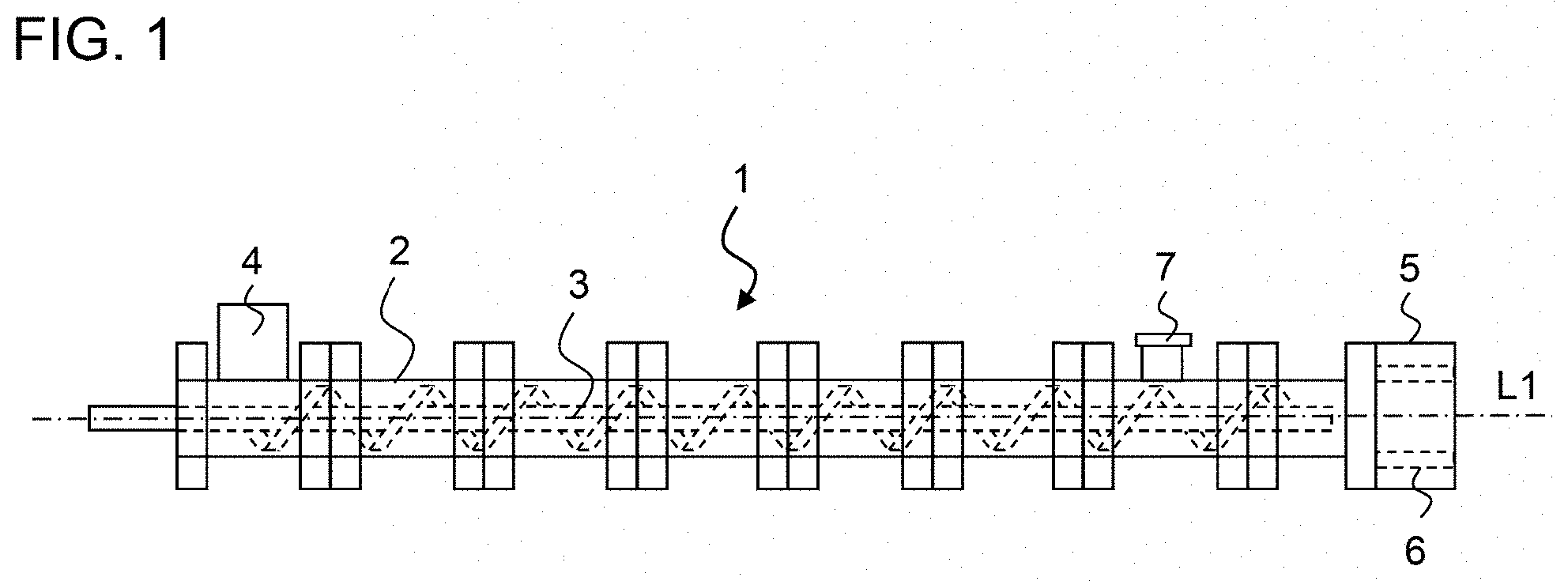
[0007] FIG. 1 is a side view of an extruder of the present invention;
[0008] FIG. 2A is a cross-sectional view of a die;
[0009] FIG. 2B is a side view of the die;
[0010] FIG. 2C is a conceptual diagram showing various degrees of opening of the opening;
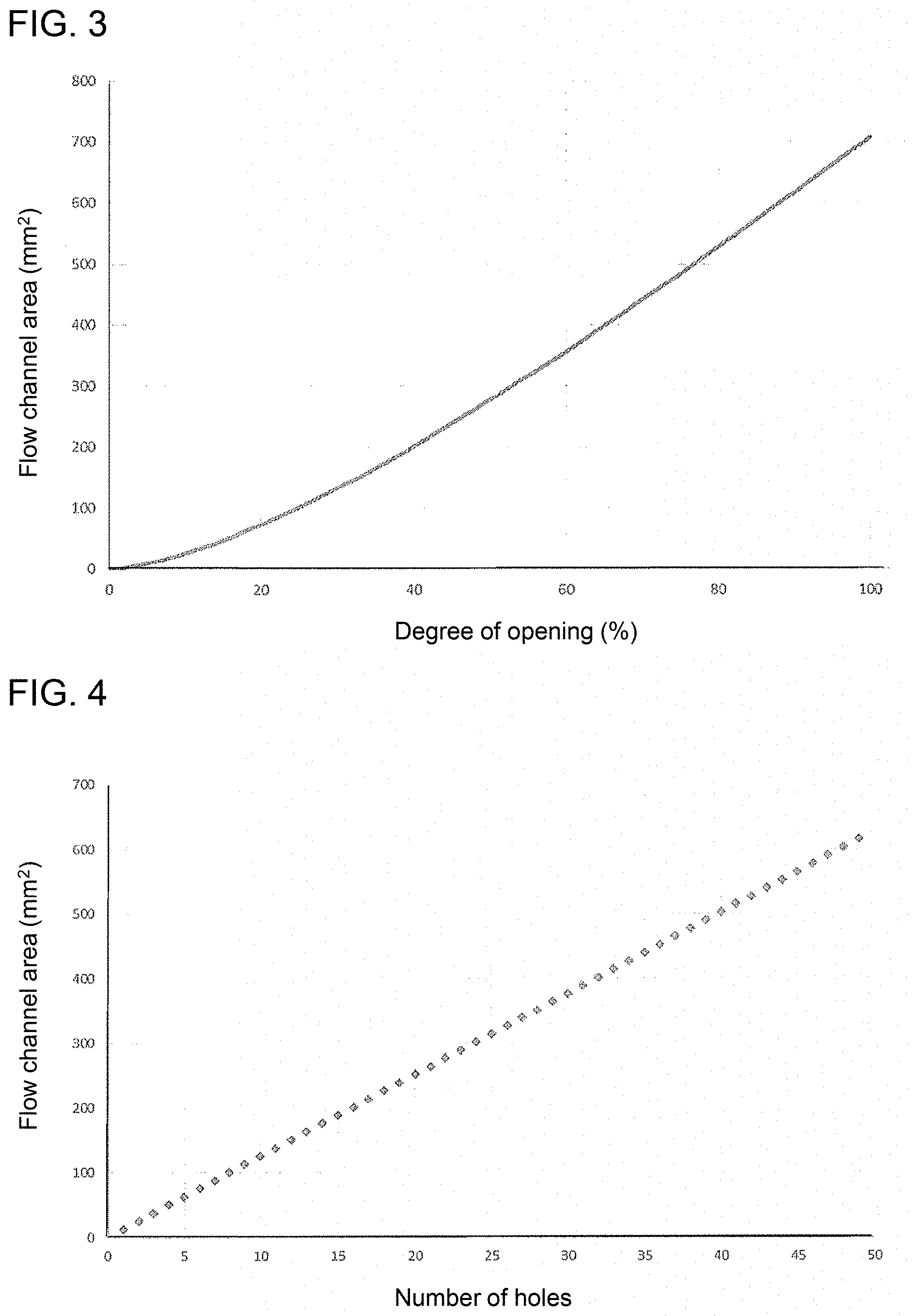
[0011] FIG. 3 is a graph showing the relationship of the flow channel area to the degree of opening of the opening in the example;
[0012] FIG. 4 is a graph showing the relationship of the flow channel area to the number of holes in the comparative example;
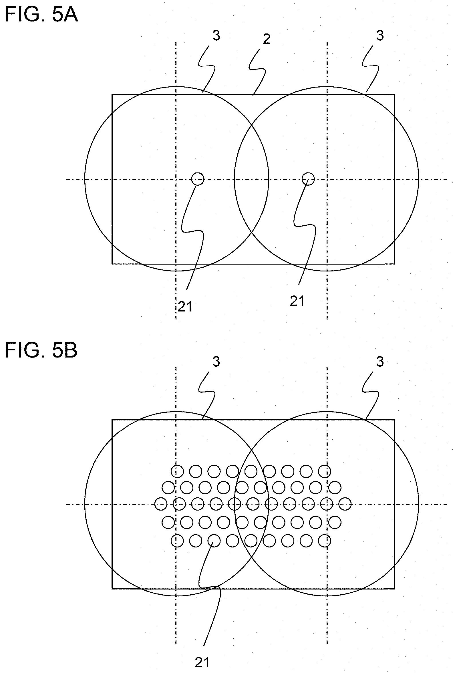
[0013] FIG. 5A is a diagram showing the arrangement of holes in Comparative Example 1;
[0014] FIG. 5B is a diagram showing the arrangement of holes in Comparative Example 2;
[0015] FIG. 6 is a graph showing the relationship of the discharge pressure to the flow channel area; and
[0016] FIG. 7 is a graph showing the relationship of the water percentage at the discharge point to the flow channel area.
DESCRIPTION OF EMBODIMENTS
[0017] Hereinafter, an extruder of the present invention will be described in detail with reference to an embodiment. The following embodiment is an example of the present invention and is not intended to limit the present invention. Although the embodiment is directed to a twin screw extruder, the present invention may also be applied to a uniaxial extruder, a multiaxial extruder, a uniaxial expansion dryer, a combination of a screw type dewaterer and an expansion dryer and the like.
[0018] FIG. 1 is a side view of twin screw extruder 1 according to an embodiment of the present invention. Twin screw extruder 1 has barrel 2 and two screws 3 that are driven to rotate in barrel 2. Two screws 3 extend in barrel 2 in parallel to longitudinal axis X1 of barrel 2. Hopper portion 4 that receives raw elastomer or raw resin (hereinafter, referred to as raw material) is formed near one of the end portions of barrel 2. Screws 3 knead the raw material while transporting the raw material. The discharge portion of barrel 2 is provided with die 5 that discharges the raw material that has been processed. Die 5 has opening 6 that discharges the raw material. Die 5 makes it possible to control the pressure of the raw material at the discharge portion of barrel 2. Vent opening 7 that discharges gas that is generated from the raw material is provided on the side wall of barrel 2 in the vicinity of the discharge portion.
[0019] FIGS. 2A and 2B schematically show the configuration of die 5. FIG. 2A is a cross-sectional view of the die, and FIG. 2B shows a side view, as viewed from direction A in FIG. 2A. Die 5 includes first and second flat plates 11, 12 that are coaxial with barrel 2 and that are arranged adjacent to each other along longitudinal axis X1 of barrel 2. In the present embodiment, first and second flat plates 11, 12 are both concentric circular plates. First flat plate 11 faces the inner space of barrel 2, and second flat plate 12 faces the outside of barrel 2. First flat plate 11 and second flat plate 12 are arranged such that they overlap with each other along the flow direction of the raw material, i.e. longitudinal axis X of barrel 2.
[0020] First flat plate 11 has a plurality of first holes 13. Second flat plate 12 has a plurality of second holes 14. Holes 13, 14 are through-holes that form opening 6 of the die. The cross-section of holes 13, 14 is circular, but is not limited thereto, and may be square, hexagonal, elliptical and the like. The number and arrangement of holes 13, 14 of first flat plate 11 is the same as the number and arrangement of holes 13, 14 of second flat plate 12. More specifically, four first holes 13 are provided at 90.degree. intervals along first circle 15, that is concentric with barrel 2, on first flat plate 11, and four second holes 14 are provided at 90.degree. intervals along second circle 16, that is concentric with barrel 2, on second flat plate 12. First circle 15 and second circle 16 have the same diameter and completely overlap with each other, as viewed in direction A in FIG. 2A.
[0021] First flat plate 11 can be rotated about longitudinal axis X1 of barrel 2 by means of a rotational drive mechanism, not shown, and second flat plate 12 is fixed to barrel 2. In another embodiment, first flat plate 11 is fixed to barrel 2, and second flat plate 12 can be rotated about longitudinal axis X1 of barrel 2 by a rotational drive mechanism, not shown. Alternatively, both first flat plate 11 and second flat plate 12 may be rotated about longitudinal axis X1 of barrel 2. In any of these configurations, at least either first flat plate 11 or second flat plate 12 is rotatable about longitudinal axis X1 of barrel 2 with respect to the other circular plate. Depending on the relative rotational angles of first flat plate 11 and second flat plate 12, the overlapping part of first holes 13 of first flat plate 11 and second holes 14 of second flat plate 12, that is, the area of opening 6, varies. In the upper figure of FIG. 2C, first hole 13 of first flat plate 11 and second hole 14 of second flat plate 12 do not overlap, and the degree of opening of opening 6 is 0%. In the middle figure of FIG. 2C, first hole 13 of first flat plate 11 and second hole 14 of second flat plate 12 partially overlap, and the degree of opening of opening 6 is 60%. In the lower figure of FIG. 2C, first hole 13 of first flat plate 11 and second hole 14 of second flat plate 12 further overlap, and the degree of opening of opening 6 is 90%. By adjusting the difference of the rotational angles of first flat plate 11 and second flat plate 12, the degree of opening of opening 6 can be continuously set. The range of rotation of first flat plate 11 or second flat plate 12 is set such that the degree of opening of opening 6 can be adjusted between 0% (fully closed) and 100% (fully open). Since the optimum pressure to be applied to the raw material varies depending on the types of the raw material, the flow channel area or the degree of opening of opening 6 is appropriately adjusted so as to obtain the optimum pressure.
[0022] The shapes of first and second flat plates 11, 12 are not limited to a circular plate, and various shapes can be used for the flat plate. The number of the circular plates is not limited to two, which is the case in the embodiment. The size and arrangement of the holes are not limited to the above-described embodiment. The holes may be provided along a plurality of concentric circles. As long as the flow channel area or the degree of opening of opening 6 can be adjusted by the relative movement of first flat plate 11 and second flat plate 12, the circular plate may slide linearly. The number of the holes is not limited to the above-described embodiment, and at least one hole may be provided on each of first flat plate 11 and second flat plate 12.
[0023] Next, the flow channel area of the opening is compared between an example and a comparative example. The die of the example is the same as that shown in FIGS. 2A and 2B. First flat plate 11 and second flat plate 12 both have four holes of .PHI.15 mm, and the degree of opening of the opening can be continuously adjusted. In the die of the comparative example, the required number of holes of .PHI.4 mm are provided in accordance with the required flow channel area. FIG. 3 shows the relationship of the flow channel area to the opening degree of the opening in the example. The degree of opening of the opening corresponds to the operation amount of the rotational drive mechanism, and the operation amount is uniformly allocated between 0, which corresponds to the fully closed state of the opening, and 100, which corresponds to the fully open state of the opening. The flow channel area shows a quadratic change with respect to the degree of opening of the opening. FIG. 4 shows the relationship of the flow channel area to the number of the holes in the comparative example. The flow channel area is in proportion to the number of the holes. A desired flow channel area can be obtained by adjusting the degree of the opening in the example. On the other hand, in the comparative example, the flow channel area that can be obtained is limited to an integral multiple of the cross-sectional area of the hole, and in some cases, only an approximate value of a desired value can be obtained.
[0024] The discharge pressure of barrel 2 (the pressure near the inlets of the holes of die 5 in barrel 2) must be accurately controlled. If the discharge pressure is high, then a tightly-packed long region is required between the screw end and the die. This may increase the temperature of the raw material while it is transported through the tightly-packed region and may degrade the raw material. If a tightly-packed long region is provided, the raw material may leak out from vent opening 7 of barrel 2 to the outside of the system, and the operation may have to be stopped. On the other hand, if the discharge pressure is too low, then the raw material is discharged from the opening of the die in an unstable manner. This may result in uneven discharging and unstable forming of the resin in the subsequent pelletizing process. In the present embodiment, a desired flow channel area and a desired discharge pressure can be accurately set because either one of the two flat plates is continuously rotated. In addition, unlike the comparative example, it is not necessary to replace a die with a die having a different number of holes in order to obtain a desired flow channel area.
[0025] Furthermore, the extruder of the present invention may be suitably applied to an expansion dewaterer that dewaters and dries water-containing raw material, such as water-containing thermoplastic resin or water-containing elastomer. When water-containing raw material, e.g. water-containing thermoplastic resin, is dewatered and dried, the fluidity of the resin that is caused by vapor pressure should be considered, unlike a common molten resin. In this case, it is difficult to adjust the discharge pressure. For example, in case of water-containing thermoplastic resin, water evaporates easily due to the rise in temperature of the resin in the region between the screw and the discharge portion of barrel 2. If molten raw material that contains vapor is ejected from the holes due to the vapor pressure in a short time, then the density of the raw material in the barrel will be reduced. Thereafter, the raw material accumulates in the barrel until the pressure is restored at the discharge point, and the pressurized and heated raw material is ejected from the die again. Such a process in which the ejection of the raw material is intermittently repeated results in a very unstable extrusion process. In addition, since the water that is contained in the raw material is also ejected at the same time, the temperature of the discharged resin is lowered, and the resin is less likely to be dried after it is discharged. If a die is suitably selected for the raw material, then these states stably change. However, determining a suitable die for a raw material requires testing of various dies, and it is very cumbersome to determine the optimal die for each of the various brands.
[0026] Since the degree of opening of opening 6 can be continuously adjusted in the embodiment, the discharge pressure can be accurately adjusted in accordance with the characteristics of the raw material that passes through the die. Therefore, the water-containing resin or the water-containing elastomer that is discharged from the die can be stably pushed out. As a result, the residual water percentage and the quality of the resin that is discharged from the extruder are stabilized. In addition, since the raw material is stably discharged from the die, water that is contained in the raw material stably evaporates, and accordingly, the raw material is stably cooled. Therefore, it is possible to prevent the resin from deteriorating and to reduce the amount of energy required for cooling.
[0027] Next, the dies of Examples and Comparative Examples were attached to a twin screw extruder TEX65.alpha.II manufactured by The Japan Steel Works Ltd., and water-containing resin (water percentage is about 50 wt %) was kneaded. In the dies of Examples, the degree of opening was set at 5% (Example 1) and 100% (Example 2). In the dies of Comparative Examples, two holes (Comparative Example 1) and 49 holes (Comparative Example 2) were provided. The arrangements of holes 21 of Comparative Example 1 and Comparative Example 2 are shown in FIGS. 5A and 5B. The twin screw extruder was operated under the same condition for Examples 1 and 2 and Comparative Examples 1 and 2. Table 1 shows the results. In the table, the water percentage at the discharge point means residual water percentage in the resin that was discharged from the die. FIG. 6 shows the relationship of the discharge pressure to the flow channel area, and FIG. 7 shows the relationship of the water percentage at the discharge point to the flow channel area. The discharge pressure increases as the flow channel area decreases. This is because high pressure is maintained upstream of the die due to the restricted flow channel area. In Comparative Example 1, since the pressure of the water-containing resin is not sufficiently maintained upstream of the die, as compared to Example 1, the temperature of the resin in the die is lowered, and the residual water percentage in the discharged resin is higher than that in Example 1. In order to limit the residual water percentage in the resin that is discharged from the die, it is necessary to adjust the flow channel area with high accuracy. Thus, the die of Examples that is capable of precisely adjusting the flow channel area can be suitably used.
TABLE-US-00001 TABLE 1 Comp. Comp. Example 1 Example 2 Example 1 Example 2 Die .PHI.15 mm .times. 4 .PHI.4 mm .times. 2 .PHI.4 mm .times. 15 Degree of opening % 5 100 Adjustment Mechanism not provided Flow channel area mm.sup.2 9 707 25 616 Discharge pressure MPag 5.3 1.8 4.3 2.4 Resin temp. in die .degree. C. 130 126 120 127 Water percentage at weight % 3.1 6.8 4.2 5.7 discharge point
Reference Signs
[0028] 1 Dewaterer
[0029] 2 Barrel
[0030] 3 Screw
[0031] 4 Hopper portion
[0032] 5 Die
[0033] 7 Opening
[0034] 11 First flat plate
[0035] 12 Second flat plate
[0036] 13 First hole
[0037] 14 Second hole
* * * * *
D00000
D00001
D00002
D00003
D00004
D00005
XML
uspto.report is an independent third-party trademark research tool that is not affiliated, endorsed, or sponsored by the United States Patent and Trademark Office (USPTO) or any other governmental organization. The information provided by uspto.report is based on publicly available data at the time of writing and is intended for informational purposes only.
While we strive to provide accurate and up-to-date information, we do not guarantee the accuracy, completeness, reliability, or suitability of the information displayed on this site. The use of this site is at your own risk. Any reliance you place on such information is therefore strictly at your own risk.
All official trademark data, including owner information, should be verified by visiting the official USPTO website at www.uspto.gov. This site is not intended to replace professional legal advice and should not be used as a substitute for consulting with a legal professional who is knowledgeable about trademark law.