Grinding Wheel Guard
Alvarez; Salvador
U.S. patent application number 16/393486 was filed with the patent office on 2020-10-29 for grinding wheel guard. The applicant listed for this patent is Salvador Alvarez. Invention is credited to Salvador Alvarez.
| Application Number | 20200338689 16/393486 |
| Document ID | / |
| Family ID | 1000004257653 |
| Filed Date | 2020-10-29 |


| United States Patent Application | 20200338689 |
| Kind Code | A1 |
| Alvarez; Salvador | October 29, 2020 |
Grinding Wheel Guard
Abstract
A guard attachment for a grinding tool has a metal body with an upper surface, a side wall along part of a perimeter of the upper surface, and a connector with which it can be attached to a grinding tool. Additional features include a bottom plate opposite the upper surface and a debris outlet attached at one end to the surface and side wall of the guard, and having a magnet removably attached to the other end. The bottom plate swivels outward from the body of the guard to facilitate changing the wheel or disk of the grinding tool. The magnet has an aperture allowing for the passage of air, but prevents sparks from escaping the guard attachment.
| Inventors: | Alvarez; Salvador; (San Diego, CA) | ||||||||||
| Applicant: |
|
||||||||||
|---|---|---|---|---|---|---|---|---|---|---|---|
| Family ID: | 1000004257653 | ||||||||||
| Appl. No.: | 16/393486 | ||||||||||
| Filed: | April 24, 2019 |
| Current U.S. Class: | 1/1 |
| Current CPC Class: | B24B 55/102 20130101; B24B 55/052 20130101 |
| International Class: | B24B 55/05 20060101 B24B055/05; B24B 55/10 20060101 B24B055/10 |
Claims
1. A wheel guard, comprising: a body, comprising: an upper surface, and a side wall along a perimeter of the upper surface; a clamp attached to the upper surface and configured to attach the wheel guard to a grinding tool; a debris outlet having a first end attached to the body and a second end; and a magnet attached to the second end of the debris outlet.
2. The wheel guard as recited in claim 1, further comprising a swivel plate parallel to the upper surface, having a perimeter located along the side wall opposite the upper surface in a first configuration, the swivel plate rotatable into a second configuration away from the body.
3. The wheel guard as recited in claim 2, further comprising a latch operable to secure the swivel plate in the first configuration.
4. The wheel guard as recited in claim 1, further comprising a clamp on the second end of the debris outlet whereby the magnet is removably attached to the second end of the debris outlet.
5. A wheel guard, comprising: a body, comprising: an upper surface, and a side wall along a perimeter of the upper surface; a clamp attached to the upper surface and configured to attach the wheel guard to a grinding tool; and a swivel plate parallel to the upper surface, having a perimeter located along the side wall opposite the upper surface in a first configuration, the swivel plate rotatable into a second configuration away from the body.
6. The wheel guard as recited in claim 5, further comprising a latch operable to secure the swivel plate in the first configuration.
7. The wheel guard as recited in claim 5, further comprising a debris outlet having a first end attached to the body and a second end.
8. The wheel guard as recited in claim 7, further comprising a magnet attached to the second end of the debris outlet.
9. The wheel guard as recited in claim 8, wherein the magnet is attached to the second end of the debris outlet by a clamp on the second end of the debris outlet.
10. The wheel guard as recited in claim 9, wherein the magnet comprises an aperture to allow air to flow out of the debris outlet.
11. A wheel guard, comprising: a body; a debris outlet having a first end attached to the body and a second end; a clamp attached to the second end of the debris outlet; a magnet removably attached to the clamp; and a bottom plate alongside the body.
12. The wheel guard as recited in claim 11, wherein the bottom plate is rotatably attached to the body by a hinge, allowing the bottom plate to rotate outward from alongside the body to a configuration away from the body to facilitate changing a wheel of a grinding tool.
13. The wheel guard as recited in claim 12, further comprising a latch engageable to secure the bottom plate in a configuration alongside the body.
14. The wheel guard as recited in claim 11, wherein the magnet comprises an aperture to allow the flow of air through the debris outlet.
Description
FIELD OF THE INVENTION
[0001] The present invention pertains generally to guards for use with grinding tools. More particularly, the present invention pertains to a guard with safety features for a grinding tool using a rotating disk or grinding wheel. The present invention is particularly, but not exclusively, useful as a guard for a handheld angle grinder.
BACKGROUND OF THE INVENTION
[0002] Tools with rotating disks or wheels often have a guard around a portion of the disk part to prevent the flight of debris and sparks in certain directions, as well as to prevent accidental contact with the rotating disk. For some tools, such as angle grinders, the wheel guards cover varying amounts of the wheel's edge, but usually not much more than about one-hundred eighty (180) degrees and generally not the whole wheel; otherwise an operator would not be able to use the tool for its grinding purposes. As a result, sparks and debris fly in directions other than those protected by the guard.
[0003] The debris, or dust, generated by a grinding tool in the course of its use can also damage an operator's lungs, even if it is initially ejected in another direction. In order to minimize the risk of lung-related diseases associated with long-term use of grinding tools, dust extraction attachments, such as dust shrouds and guards with dust extraction features, are marketed for grinding tools. These dust extraction attachments have a dust evacuation channel for connection to a vacuum system in order to remove dust generated by the tool. Dust extraction attachments provide an important health benefit, but it is not always practical to have a vacuum at a work site. Moreover, hot flaming sparks can burn vacuum components and the content of vacuum receptacles.
[0004] In light of the above, it would be advantageous to provide a grinding disk guard with features to collect or otherwise minimize the ejection of sparks and debris from a grinding tool.
SUMMARY OF THE INVENTION
[0005] Disclosed is a guard attachment for a grinding tool. The guard has a metal body with an upper surface, a side wall along part of a perimeter of the upper surface, and a connector with which it can be attached to a grinding tool. Preferred embodiments have a bottom plate opposite and parallel to the upper surface and a debris outlet attached at one end to the surface and side wall of the guard, and having a magnet removably attached to the other end. In a preferred embodiment, the bottom plate swivels outward from alongside the body of the guard to facilitate changing the wheel or disk of the grinding tool. In an alternative embodiment, the bottom plate is removably attached to the body of the guard. The magnet has an aperture allowing for the passage of air, but prevents sparks from escaping the guard.
[0006] Debris and sparks entering into the guard in the course of using a grinding tool are directed by the upper surface, bottom plate, and side wall into the debris outlet. As a result, the quantity of sparks and debris escaping the grinding tool is minimized.
BRIEF DESCRIPTION OF THE DRAWINGS
[0007] The novel features of this invention, as well as the invention itself, both as to its structure and its operation, will be best understood from the accompanying drawings, taken in conjunction with the accompanying description, in which similar reference characters refer to similar parts, and in which:
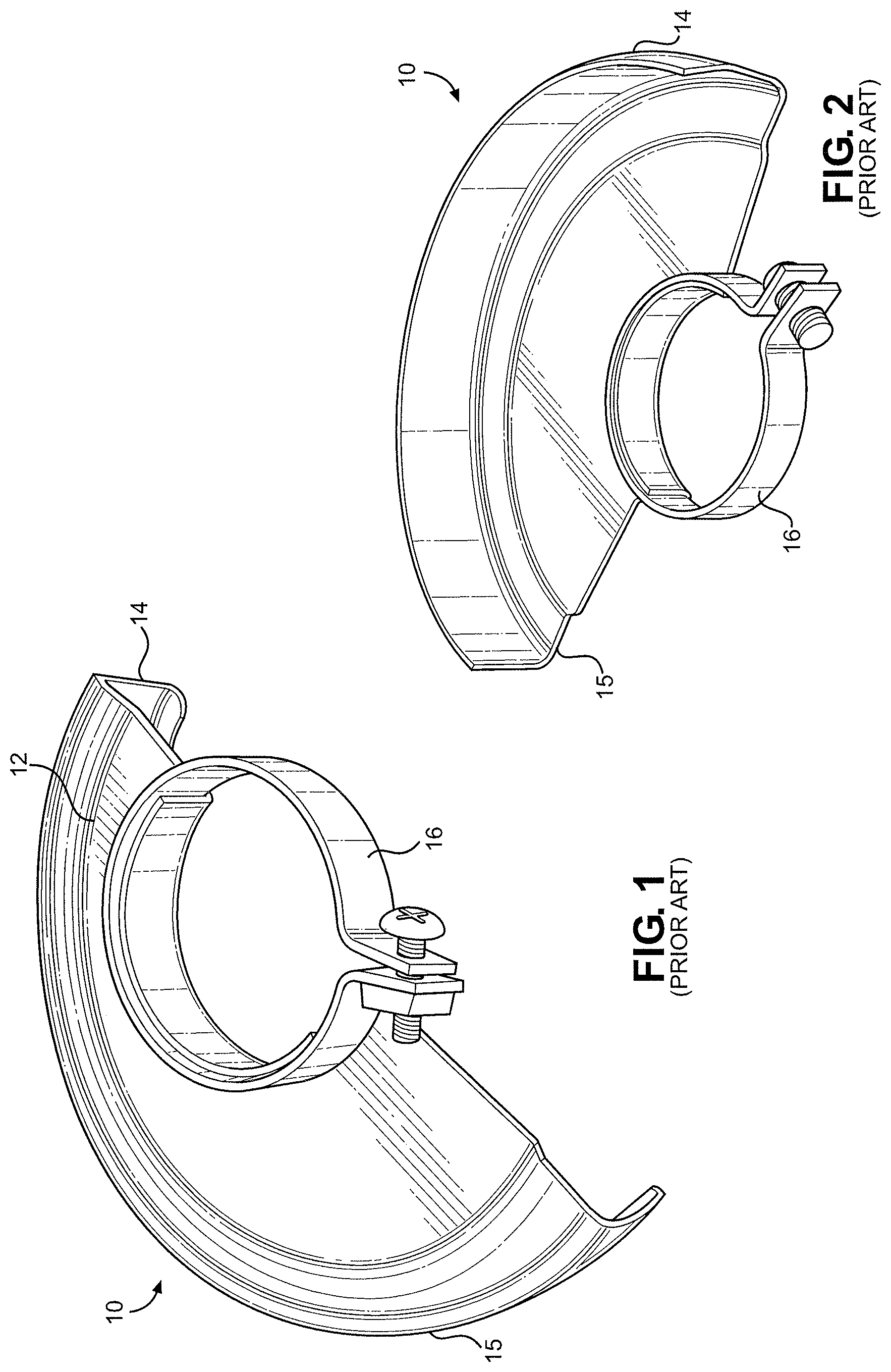
[0008] FIG. 1 is a top perspective view of a prior art wheel guard;
[0009] FIG. 2 is a bottom perspective view of the wheel guard of FIG. 1;
[0010] FIG. 3 is a top perspective view of a preferred embodiment of a wheel guard of the present invention;
[0011] FIG. 4 is a bottom perspective view of the wheel guard of FIG. 3;
[0012] FIG. 5 is a bottom perspective view of the wheel guard of FIG. 3 with the bottom plate in an open configuration;
[0013] FIG. 6 is a top perspective view of the wheel guard of FIG. 3 with the magnet removed;
[0014] FIG. 7 is a top perspective view of a grinding tool to which the wheel guard of FIG. 3 is attached;
[0015] FIG. 8 is a bottom perspective view of a grinding tool to which the wheel guard of FIG. 3 is attached; and
[0016] FIG. 9 is a top perspective view of a grinding tool to which the wheel guard of FIG. 3 is attached, illustrating an elongated magnet facilitating the attachment of a vacuum to the debris outlet.
DETAILED DESCRIPTION
[0017] Referring initially to FIG. 1, a top perspective view of a prior art wheel guard 10 is illustrated. Wheel guard 10 has an upper surface 12, usually in the shape of a partial circle, and a side wall 14 around the perimeter of the curved portion of the partial circle. The upper surface 12 and side wall 14 form the body 15 of the wheel guard 10, partially protecting the user of a grinding tool from debris and sparks. The wheel guard 10 is commonly made of steel. A clamp 16 allows the wheel guard 10 to be attached to a grinding tool.
[0018] Referring now to FIG. 2, a bottom perspective view of prior art wheel guard 10 is shown, showing the side wall 14 and the underside of upper surface 12. In use, wheel guard 10 is mounted on a grinding tool so that upper surface 12 and side wall 14 cover a portion of the tool's grinding wheel or grinding disk, protecting an operator from sparks, debris, and pieces of the wheel or disk that may be ejected at high velocity when broken.
[0019] Referring now to FIG. 3, a top perspective view of a preferred embodiment of a wheel guard 100 of the present invention is illustrated. Wheel guard 100 has an upper surface 112 and a side wall 114 (shown in FIG. 4) defining a body 102 made of a metal such as steel in preferred embodiments. A connector 116, such as a clamp, allows the wheel guard 100 to be attached to a grinding tool to partially cover a grinding wheel or disk. Connector 116 is attached at the center of upper surface 112 in preferred embodiments. A debris outlet 118 is attached to the body of the wheel guard 100 in a position to capture and direct debris and sparks when the grinding tool is in use. A magnet 120 attached to the distal end of the debris outlet 118 prevents sparks from escaping the debris outlet 118. In a preferred embodiment, magnet 120 is removably attached to the debris outlet 118 with a clamp 122 attached to the distal end of the debris outlet 118.
[0020] Referring now to FIG. 4, a bottom perspective view of wheel guard 100 is shown, illustrating a swivel plate 124 connected to the body 102 of wheel guard 100 by a hinge 126. A latch 128 secures the swivel plate 124 in place opposite the upper surface 112. Latch 128 is depicted as a swing latch for illustrative purposes. Various embodiments include a swing latch, a magnetic clasp, a latch characterized by snapping into and out of its engaged configuration, a buckle latch, and other latches and latching mechanisms known in the art.
[0021] The upper surface 112, side wall 114, and swivel plate 124 define an interior of the wheel guard 100 which surrounds a portion of the grinding disk or grinding wheel of the tool to which the wheel guard 100 is attached. Due to the rotation of the disk or wheel during use of the tool, sparks and debris enter the interior of the wheel guard 100 with a momentum in a direction such that they are guided by the side wall 114, and, as necessary, the upper surface 112 and swivel plate 124, toward the debris outlet 118.
[0022] As illustrated in FIG. 5, by disengaging the latch 128, the swivel plate 124 can be swung in direction 129 into an open configuration for changing the wheel or disk on a grinding tool to which the wheel guard 100 is attached. After attaching a grinding wheel or grinding disk to the tool, swivel plate 124 is returned to its closed configuration and secured by engaging latch 128.
[0023] Referring now to FIG. 6, a top perspective view of wheel guard 100 is shown with magnet 120 detached from the distal end of debris outlet 118. Magnet 120 is normally attached to the end of debris outlet 118 by clamp 122 located on the distal end of debris outlet 118, but can be removed and replaced by engaging clamp 122. A preferred embodiment of magnet 120 has an aperture 130 in order to allow for the passage of air through and out of debris outlet 118. Aperture 130 has a diameter 132 at a predetermined ration to the thickness 134 of the magnet 120. Thus, a thinner magnet 120 needs a smaller aperture 130 to be effective, while a thicker magnet 120 may have a larger aperture 130.
[0024] Referring now to FIG. 7, wheel guard 100 is illustrated as attached to a grinding tool 140. When installed and in use, wheel guard 100 partially covers grinding wheel 142 in order to protect an operator from sparks and debris. Debris is collected in debris outlet 118; as necessary, the wheel guard 100 can be cleaned to remove the debris and replaced onto grinding tool 140. Alternatively, magnet 130 can be removed to clean debris out of debris outlet 118, and replaced without removing wheel guard 100 in its entirety from grinding tool 140.
[0025] Referring now to FIG. 8, swivel plate 124 covers a portion of the bottom of grinding wheel 142 in order to minimize the escape of debris and sparks, but can be opened to install or change grinding wheel 142 without removing wheel guard 100 from grinding tool 140.
[0026] Referring now to FIG. 9, an alternative preferred embodiment of wheel guard 100 includes a magnet 120 with a sufficiently long thickness 134 to allow a wide enough aperture 132 to facilitate air flow to an attached vacuum 150. Debris outlet 118 and magnet 120 are sized and shaped to receive a vacuum hose 152 connecting wheel guard 100 to vacuum 150. The magnet prevents flaming sparks from entering vacuum 150, thus avoiding damaging the components of vacuum 150 and further avoiding fire hazards from the ignition of the contents of the receptacle of vacuum 150.
[0027] While there have been shown what are presently considered to be preferred embodiments of the present invention, it will be apparent to those skilled in the art that various changes and modifications can be made herein without departing from the scope and spirit of the invention.
* * * * *
D00000
D00001
D00002
D00003
D00004
D00005
XML
uspto.report is an independent third-party trademark research tool that is not affiliated, endorsed, or sponsored by the United States Patent and Trademark Office (USPTO) or any other governmental organization. The information provided by uspto.report is based on publicly available data at the time of writing and is intended for informational purposes only.
While we strive to provide accurate and up-to-date information, we do not guarantee the accuracy, completeness, reliability, or suitability of the information displayed on this site. The use of this site is at your own risk. Any reliance you place on such information is therefore strictly at your own risk.
All official trademark data, including owner information, should be verified by visiting the official USPTO website at www.uspto.gov. This site is not intended to replace professional legal advice and should not be used as a substitute for consulting with a legal professional who is knowledgeable about trademark law.