Grinding Tool, And Main Component And Grinding Component Thereof
SUN; Yimin ; et al.
U.S. patent application number 16/635843 was filed with the patent office on 2020-10-29 for grinding tool, and main component and grinding component thereof. The applicant listed for this patent is Positec Power Tools (Suzhou) Co., Ltd.. Invention is credited to Shaoshan Ji, Jie Mei, Fu Qian, Yimin SUN, Hongbing Wu, Shisong Zhang, Hongfeng Zhong.
| Application Number | 20200338686 16/635843 |
| Document ID | / |
| Family ID | 1000004969491 |
| Filed Date | 2020-10-29 |


View All Diagrams
| United States Patent Application | 20200338686 |
| Kind Code | A1 |
| SUN; Yimin ; et al. | October 29, 2020 |
GRINDING TOOL, AND MAIN COMPONENT AND GRINDING COMPONENT THEREOF
Abstract
A grinding tool comprises: a main component, the main component comprises a housing, a motor, and an output assembly driven by the motor to rotate; and a grinding component, detachably connected to the main component, the grinding component including a grinding body, and an input assembly rotating relative to the grinding body. The main component comprises a first connector, the input assembly includes a second connector, and the first connector is operably movable relative to the second connector to enable the first connector to be joined to the second connector. So that the output assembly is capable of driving the input assembly to drive the body to move. The grinding tool is simple in structure and easy to operate. The application further discloses a main component of a grinding tool and a grinding component of a grinding tool.
| Inventors: | SUN; Yimin; (Jiangsu, CN) ; Qian; Fu; (Jiangsu, CN) ; Zhang; Shisong; (Jiangsu, CN) ; Zhong; Hongfeng; (Jiangsu, CN) ; Wu; Hongbing; (Jiangsu, CN) ; Ji; Shaoshan; (Jiangsu, CN) ; Mei; Jie; (Jiangsu, CN) | ||||||||||
| Applicant: |
|
||||||||||
|---|---|---|---|---|---|---|---|---|---|---|---|
| Family ID: | 1000004969491 | ||||||||||
| Appl. No.: | 16/635843 | ||||||||||
| Filed: | August 6, 2018 | ||||||||||
| PCT Filed: | August 6, 2018 | ||||||||||
| PCT NO: | PCT/CN2018/099070 | ||||||||||
| 371 Date: | July 13, 2020 |
| Current U.S. Class: | 1/1 |
| Current CPC Class: | B24B 23/028 20130101 |
| International Class: | B24B 23/02 20060101 B24B023/02 |
Foreign Application Data
| Date | Code | Application Number |
|---|---|---|
| Aug 4, 2017 | CN | 201710661162.3 |
| Jan 15, 2018 | CN | 201810034934.5 |
Claims
1-25. (canceled)
26. A grinding tool, comprising: a main component comprises a housing, a motor disposed in the housing, and an output assembly being rotatably driven by the motor; and a grinding component detachably connected to an underside of the main component, the grinding component comprises a grinding body and an input assembly located on the grinding body, the input assembly is rotatable around a first pivot axis relative to the grinding body; wherein the main component further comprises a first connecting member with a first joining portion movably relative to the housing, the input assembly comprises a second joining portion for cooperating with the first joining portion and an eccentric portion with a central axis parallel to and spaced apart the first pivot axis; the first connecting member being configured to be operably movable relative to the input assembly to make the first joining portion connect with the second joining portion, so that the grinding component is connected to the underside of the main component and is movably driven by the motor relative to the housing.
27. The grinding tool according to claim 26, wherein the grinding tool further comprises a locking mechanism configured to lock the input assembly relative to the housing.
28. The grinding tool according to claim 27, wherein the locking mechanism comprises a first locking member non-rotatably movable relative to the housing, and a second locking member configured to fixed relative to the input assembly during the connection of the grinding component to the main component, the first locking member is movable between a first position being separated from the second locking member and a second position being engaged with the second locking member so as to lock the input assembly relative to the housing.
29. The grinding tool according to claim 28, wherein the main component further comprises an operating member configured to be operably switched between an open state and a closed state, when the operating member is in the closed state, the first locking member is separated from the second locking member; when the operating member is in the open state, the first locking member is movable from the first position to the second position and the operating member is operable to drive the first connecting member to rotate relative to the input assembly to make the first joining portion connect with the second joining portion.
30. The grinding tool according to claim 26, wherein the main component further comprises a hollow shaft surrounding the first connecting member, the hollow shaft is configured to be fixed relative to the output assembly so as to rotate with the output assembly; the hollow shaft comprises a first support portion at a first end, and the input assembly comprises a second support portion at a second end, the second support portion is configured to engage with the first support portion for central positioning of the main component and grinding component.
31. The grinding tool according to claim 30, the output assembly comprises a plurality of first ratchet splines circumferentially distributed on the hollow shaft, the input assembly comprises a plurality of second ratchet splines configured to mesh with the first ratchet splines for transmitting rotation of the output assembly.
32. The grinding tool according to claim 26, wherein the first joining portion comprises external thread located on the first connecting member, the second joining portion comprises internal thread located in a mounting hole of the input assembly.
33. The grinding tool according to claim 26, wherein the output assembly further comprises a first driving wheel arranged coaxially with the rotation axis of the motor, and a second driving wheel driven by the first driving wheel, the rotation axis of the first driving wheel is parallel to and spaced from the rotation axis of the second driving wheel, the input assembly connect with the second driving wheel.
34. The grinding tool according to claim 33, wherein the main component further comprises a first fan arranged below and coaxial with the motor, and a second fan arranged below the second driving wheel.
35. The grinding tool according to claim 34, wherein the housing comprises at least one air inlet and at least one air outlet, the at least one air inlet is located at an upper end of the housing and away from the grinding component, the air outlet is located close to the second fan, air flows into the housing from the air inlet under the action of the first fan and through the motor, and flows out from the air outlet under the action of the second fan.
36. A main component of a grinding tool, configured to be detachably connected to an underside of a grinding component of the grinding tool, the main component comprises: a housing; a motor disposed in the housing and configured to provide a rotary power; and an output assembly configured to be driven by the motor to transmit the rotary power to an input assembly of the grinding component; wherein the main component further comprising a first connecting member movably disposed on the housing, the first connecting member is configured to join with the input assembly and driven by the output assembly to rotate relative to the housing when the grinding component is installed on the main component.
37. The main component according to claim 36, wherein the main component further comprises a hollow shaft sheathing over the first connecting member, the output assembly fixed relative to the hollow shaft, the hollow shaft is rotatable relative to the housing when the output component driven by the motor.
38. The main component according to claim 37, wherein the first connecting member is configured movable relative to the hollow shaft during the installation of the grinding component to the underside of the main component.
39. The main component according to claim 37, wherein the first connecting member comprises an lower end with external thread extends out of the hollow shaft, the input assembly comprises a threaded hole with internal thread, the lower end of the first connecting member is configured to engaged with the threaded hole of the input assembly when the first connecting member rotates relative to the housing.
40. The main component according to claim 37, wherein the output assembly comprises a plurality of ratchet splines circumferentially distributed on the hollow shaft, the input assembly comprises a plurality of second ratchet splines configured to mesh with the first ratchet splines for transmitting the rotation of the output assembly.
41. The main component according to claim 36, wherein the main component further comprises a locking mechanism configured to operably switched between a locked state and an unlocked state, when the locking mechanism in the locked state, the locking mechanism prevent the hollow shaft from rotating relative to the housing, when the locking mechanism in the unlocked state, the hollow shaft is released by the locking mechanism so as to rotate relative to the housing.
42. A grinding component of a grinding tool, configured to be detachably joined to a main component of the grinding tool, the grinding component comprising: a grinding body; an input assembly located on the grinding body, the input assembly is configured to connect with an output assembly of the main component to drive the grinding component moving relative to the main component, wherein the input assembly is rotatable around a first pivot axis relative to the grinding body, the input assembly comprises a second joining portion and an eccentric portion having a centre axis parallel to and spaced apart the first pivot axis, the second joining portion is configured to connect with a first connecting member of the main component so as to connect the grinding component to the main component of the grinding tool.
43. The grinding component according to claim 42, wherein the second joining portion comprises a mounting hole with internal thread, the input assembly further comprising a second support portion being configured as a groove coaxial with the mounting hole, the outer diameter of the groove is greater than an outer diameter of the mounting hole.
44. The grinding component according to claim 43, wherein the groove, the mounting hole and the first pivot axis are collinear.
45. The grinding component according to claim 44, wherein the input assembly further comprises a plurality of ratchet splines disposed on the periphery of the second support portion for transmitting torque in cooperation with the output assembly.
Description
[0001] This application is a National Stage application of International Application No. PCT/CN2018/099070 filed Aug. 6, 2018, and claims priority to Chinese Application Nos. 201710661162.3 filed Aug. 4, 2017 and 201810034934.5 filed Jan. 15, 2018, each of which are hereby incorporated by reference in their entirety as if fully set forth herein.
BACKGROUND
Technical Field
[0002] The present invention relates to a handheld power tool, and in particular, to a grinder having multiple grinding components (platens) that can be selectively attached to a commom main component.
Related Art
[0003] Grinder, according to its grinding components, typically include a circular grinder whose grinding component having a circular plate body, and a non-circular grinder whose grinding component having a noncircular plate body. An output shaft of the circular grinder drives a grinding component to make a random-orbit movement composed by a regular eccentric swinging and an irregular rotation. The circular sander is configured to sand a larger quantity of material, for example, is used for rough grinding. For the non-circular grinder, the irregular rotation of the grinding component is limited. Therefore, the grinding component only has its regular eccentric swinging. The non-circular grinder is configured to sand a little quantity of material, for example, is used for detail grinding.
[0004] When the grinding component moves, different kinds of shape can adapt to different perating conditions. For example, a rectangular shape grinding component can be used for sanding under normal operating conditions. A triangular shape grinding component is obviously more advantageous when sanding a working surface in a corner area. A special-shaped grinding component with a finger shape is more suitable for sanding a working surface with a narrow area.
[0005] A sander adaptable to various operating conditions brings convenience to users and therefore becomes widely popular in the market. The various operating conditions herein include operating condition requirements of detail sanding and rough sanding, or different base shapes can meet operating conditions in different sanding areas. The sander adaptable to various operating conditions is referred to as a multifunctional grinder below.
[0006] For the multifunctional grinder, to obtain a plurality of functions, it is a common way to change its grinding components. When a circular grinding component is mounted to the main component of the grinder, the base makes a random orbital movement including a regular eccentric swinging and a non-irregular rotation without being restricted by a swing foot. When a non-circular grinding component is mounted to the main component of the grinder, the base is restricted by the swing foot and makes an orbital movement including only a revolution. The multifunctional grinder can meet different sanding areas by changing different shaped grinding components with a base replacement structure.
[0007] Chinese Patent Application CN103506923A and U.S. Pat. No. 8,821,220B disclose abase replacement structure. In U.S. Pat. No. 8,821,220B, a grinder component includes a base body used to mount sandpaper and an input assembly that is located in the base body and driven by a motor and can rotate relative to the base body. The grinder component and the main component are axially locked along an axis of the motor by a connecting mechanism. The connecting mechanism includes a special-shaped locking steel wire located in the main component and a clamping slot corresponding to the special-shaped locking steel wire is located in the grinding component. Because the locking steel wire and the clamping slot of the connecting mechanism are non-rotatable, a torque transfer mechanism is used between the main component and grinding component for torque transferring. The base body and the input assembly are moving during work, so that the grinding component also needs to include a fixed substrate housing in which the clamping slot is provided. Therefore, for the grinding component, a bearing needs to be disposed between the base body and the input assembly, and another bearing needs to be disposed between the substrate housing and the input assembly, so that the input assembly can move relative to the substrate body. This base replacement structure makes the structure of the grinding component complex and costly.
[0008] Based on the current state of the prior art, it is necessary to improve a base replacement structure of a multifunctional sander to overcome the problems in the prior art.
SUMMARY
[0009] The present invention provides a grinding tool having a simple and convenient base replacement structure.
[0010] A technical solution provided in the present invention is as follows: A grinding tool, comprising: a main component, the main component comprising a housing, a motor disposed in the housing, and an output assembly driven by the motor to rotate; and a grinding component, detachably connected to the main component, comprising a grinding body and an input assembly and can rotate around a first pivot axis relative to the grinding body, wherein the main component further comprises a first connecting member that is movably disposed relative to the housing, the input assembly comprises a second connecting member and an eccentric element whose central axis is paralle relative to the first pivot axis, the grinding body is connected to the eccentric element, and the first connecting member is operably movable relative to the second connecting member to enable the first connecting member to be joined to the second connecting member, so that the output assembly is capable of driving the input assembly to rotate around the first pivot axis to drive the grinding body to work.
[0011] Preferably, when the first connecting member is joined to the second connecting member, the grinding component is inseparable from the main component in the axial direction.
[0012] Preferably, the grinding tool further includes a locking mechanism, and the locking mechanism is capable of fastening the second connecting member relative to the housing.
[0013] Preferably, the locking mechanism includes a first locking member movable between a locked position and a released position relative to the housing, and a second locking member, the second locking member and the second connecting member being non-rotatable relative to each other; when the first locking member is in the locked position, the first locking member is joined to the second locking member, and the second connecting member is fixed relative to the housing; and when the first locking member is in the released position, the first locking member is separate from the second locking member, and the second connecting member is rotatable relative to the housing.
[0014] Preferably, the first locking member is located in the main component, and the second locking member is located in the grinding component.
[0015] Preferably, the first connecting member includes a first support portion, and the second connecting member includes a second support portion used to be joined to the first support portion.
[0016] Preferably, a hollow shaft is disposed on an outer side of the first connecting member, the hollow shaft is fixedly disposed relative to the output assembly, a first support portion is disposed at an end, close to the grinding component, of the hollow shaft, and the second connecting member includes a second support portion used to be joined to the first support portion.
[0017] Preferably, the second support portion is disposed to be a groove, and an outer diameter of the first support portion matches an inner diameter of the groove.
[0018] Preferably, the central axis of the first support portion is collinear with the first pivot axis.
[0019] Preferably, the first connecting member is provided with a first joining portion, and the second connecting member includes a second joining portion used to be joined to the first joining portion.
[0020] Preferably, the first joining portion is provided with an external thread, the second joining portion is disposed to be a mounting hole, and the mounting hole is provided with an internal thread that matches the external thread.
[0021] Preferably, the central axis of the first joining portion is collinear with the first pivot axis.
[0022] Preferably, the output assembly includes an output portion, the input assembly includes an input portion used to be joined to the output portion, and when the first connecting member is joined to the second connecting member, the output portion is joined to the input portion to transfer the rotation of the motor to the input assembly.
[0023] Preferably, the input portion includes a plurality of second ratchet splines distributed circumferentially, and the output portion includes a plurality of first ratchet splines meshing with the second ratchet splines.
[0024] Preferably, the pivot axis of the first connecting member is collinear with the first pivot axis.
[0025] Preferably, the main component includes an elastic swing foot fixedly disposed relative to the housing, and the grinding component is provided with a limiting foot joined to the elastic swing foot.
[0026] Preferably, the output assembly includes a first driving wheel driven by the motor and a second driving wheel driven by the first driving wheel, and the pivot axis of the first driving wheel is parallel to and spaced from the pivot axis of the second driving wheel.
[0027] Preferably, the grinding tool further includes a second fan, the second fan and the second driving wheel being fixedly disposed relative to each other, and a first fan that is coaxial with the motor and is located at an end, close to the grinding component, of the motor.
[0028] Preferably, the housing is provided with at least one air inlet and at least one air outlet, the air inlet is located at an end, away from the grinding component, of the motor, the air outlet is disposed close to the second fan, and an external airflow flows into the housing from the air inlet under the action of the first fan and then flows through the motor, and flows out of the air outlet under the action of the second fan.
[0029] The technical solution is used in the present invention, thereby simplifying the structure of the grinding component, and facilitating the disassembly and assembly between the grinding component and the main component.
[0030] The present invention further provides a main component that facilitates the disassembly and assembly of a grinding component.
[0031] A technical solution provided in the present invention is as follows: A main component of a grinding tool is used to be connected to a detachable grinding component of the grinding tool. The main component includes: a housing; a motor, accommodated in the housing, and configured to provide rotary power; and an output assembly, capable of being driven by the motor to rotate relative to the housing, where the main component further includes a first connecting member movably disposed on the housing, and the first connecting member is used to be joined to the grinding component and is capable of being driven by the output assembly to rotate relative to the housing.
[0032] Preferably, the first connecting member includes a first joining portion, and the first joining portion is provided with an external thread.
[0033] Preferably, the main component further includes a hollow shaft sleeved over the first connecting member, and the first connecting member is operably movable relative to the hollow shaft.
[0034] Preferably, the output assembly includes an output portion, and the output portion is fixedly connected to the hollow shaft.
[0035] Preferably, the main component further includes a locking mechanism, the locking mechanism has a locked state and an unlocked state, the locking mechanism is capable of preventing the hollow shaft from rotating relative to the housing when the locking mechanism is in the locked state, and the hollow shaft is rotatable relative to the housing when the locking mechanism is in unlocked state.
[0036] Preferably, the main component further includes an operating mechanism, and the operating mechanism includes an operating member that is capable of controlling the locking mechanism to switch between the locked state and the unlocked state.
[0037] Preferably, the operating member is capable of switching between a first position and a second position, the operating member at least partially protrudes from the housing when being in the first position, and the operating member does not protrude from an outer contour of the housing when being in the second position.
[0038] Preferably, when the operating member switches to the first position, the locking mechanism switches to the locked state, and when the operating member switches to the second position, the locking mechanism switches to the unlocked state.
[0039] Preferably, the locking mechanism includes a first locking member fixedly disposed relative to the hollow shaft, a second locking member fixedly disposed relative to the housing, and a first elastic member disposed between the housing and the second locking member; when the operating member is in the first position, the first elastic member is in a released state, and the first locking member is joined to the second locking member; and when the operating member is in the second position, the operating member abuts against the second locking member to enable the elastic element to be in a compressed state, and the first locking member is separate from the second locking member.
[0040] Preferably, the first connecting member includes a transmission element, and the operating member operably drives the first connecting member to move through the transmission element.
[0041] Preferably, the operating mechanism further includes a seat rotatable around a second pivot axis relative to the housing, the operating member is capable of pivoting between a first operation position and a second operation position relative to the seat, when the operating member is in the first operation position, the operating member is separate from the transmission element, and when the operating member is in the second operation position, the operating member is joined to the transmission element, so as to drive the first connecting member to rotate around the second pivot axis.
[0042] Preferably, the output assembly includes an output portion, and the output portion is rotatable around a third pivot axis and includes a plurality of ratchets circumferentially distributed around the third pivot axis.
[0043] Preferably, the third pivot axis is parallel to and spaced from an axis of the motor.
[0044] Preferably, the housing is provided with a holding handle extending at an angle to the axis of the motor, and the axis of the motor and the holding handle are separately located on two opposite sides of the third pivot axis.
[0045] Preferably, the output assembly includes an output shaft, and the output shaft is coaxially disposed with and fixedly connected to the first connecting member.
[0046] Preferably, the main component further includes two pairs of limiting feet, each pair of limiting feet being disposed diagonally.
[0047] The present invention further provides a grinding component that is easily joined to a main component of a grinding tool.
[0048] A technical solution provided in the present invention is as follows: A grinding component of a grinding tool is used to be detachably joined to a main component of the grinding tool. The grinding component includes: a grinding body; an input assembly accommodated at least partially in the grinding body, where the input assembly is rotatable around a first pivot axis relative to the grinding body, the input assembly includes an eccentric element, the centre axis of the eccentric element is eccentrically disposed relative to the first pivot axis, the body is connected to the eccentric element, the input assembly further includes a second connecting member, the second connecting member and the eccentric element being fixedly disposed relative to each other, and the second connecting member is capable of being joined to the main component.
[0049] Preferably, the grinding body includes a cover body sleeved on an outer side of the second connecting member and a plate body axially fixed to the cover body and located below the cover body, the plate body is used to mount a sanding element, and the second connecting member includes a second joining portion and a second support portion connected to the second joining portion.
[0050] Preferably, the second joining portion is disposed to be a mounting hole extending in a pivot axis direction, the second support portion is disposed to be a groove extending in the pivot axis direction, and a lower end of the mounting hole is closer to the plate body than a lower end of the groove.
[0051] Preferably, the second connecting member includes a mounting hole extending in a first pivot axis direction, and the mounting hole is provided with an internal thread.
[0052] Preferably, the second connecting member further includes a groove extending in the first pivot axis direction, and the groove is in communication with the mounting hole.
[0053] Preferably, an outer diameter of the groove is greater than an outer diameter of the mounting hole.
[0054] Preferably, a ratio of an axial size and an outer diameter size of the second support portion is between 0.33 and 1.7.
[0055] Preferably, a central axis of the groove and a central axis of the mounting hole are collinear with the first pivot axis.
[0056] Preferably, the input assembly further includes an input portion configured to transfer torque, and the input portion is fixedly disposed relative to the second connecting member.
[0057] Preferably, the output portion includes a plurality of ratchets circumferentially distributed around the first pivot axis.
[0058] Preferably, the input assembly further includes a counterbalance, a central axis of the eccentric element is located on one side of the first pivot axis, and the counterbalance is located on the other side, opposite to the central axis, of the first pivot axis.
[0059] Preferably, the counterbalance is located at an end, away from the input portion, of the eccentric element.
[0060] Preferably, the body includes a cover body sleeved on an outer side of the second connecting member and a plate body axially fixed to the cover body, the plate body is used to mount a sanding element, and the plate body may be disposed to be circular, rectangular, or irregularly shaped.
BRIEF DESCRIPTION OF THE DRAWINGS
[0061] FIG. 1 is a schematic diagram of an operating member being in a closed state according to a first implementation of the present invention.
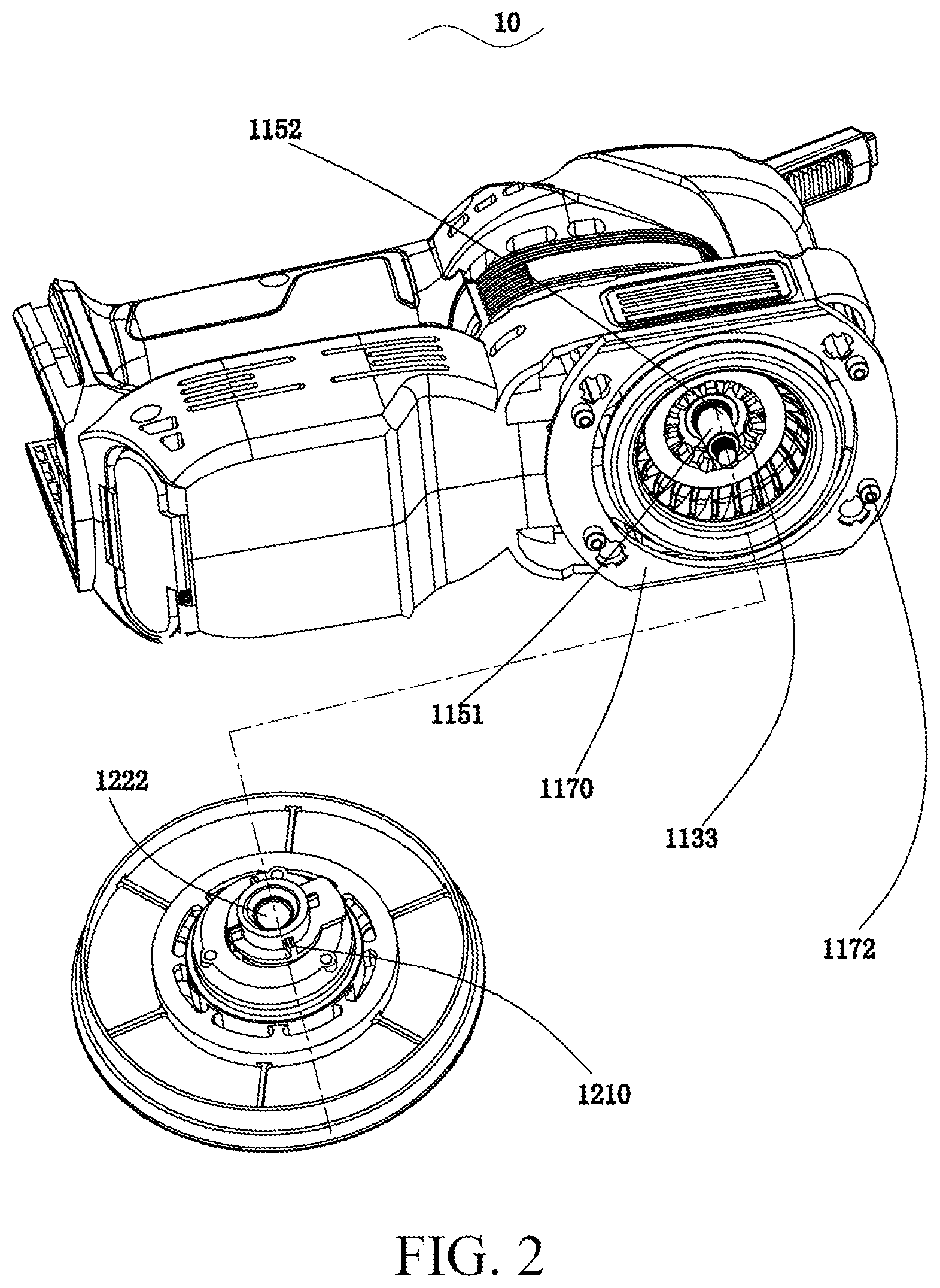
[0062] FIG. 2 is a schematic structural diagram of a joint between a main component and a grinding component according to the first implementation of the present invention.
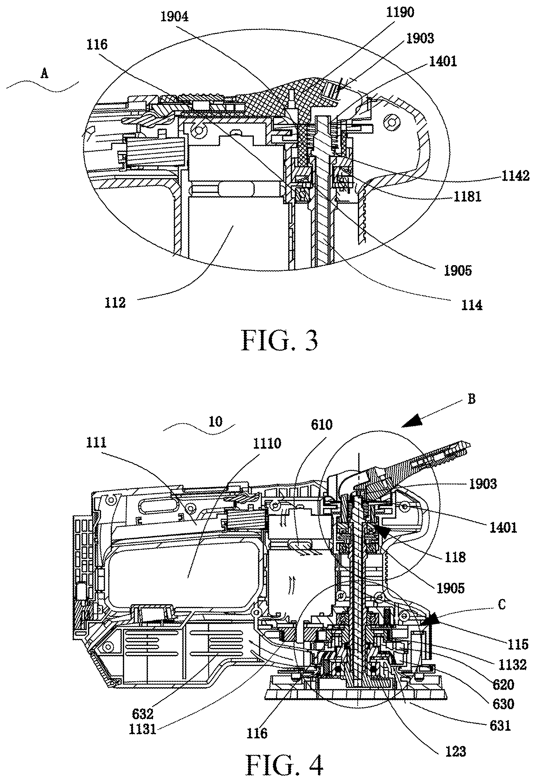
[0063] FIG. 3 is a partially enlarged view of a part A in FIG. 1.
[0064] FIG. 4 is a schematic diagram of an operating member being in an open state according to the first implementation of the present invention.
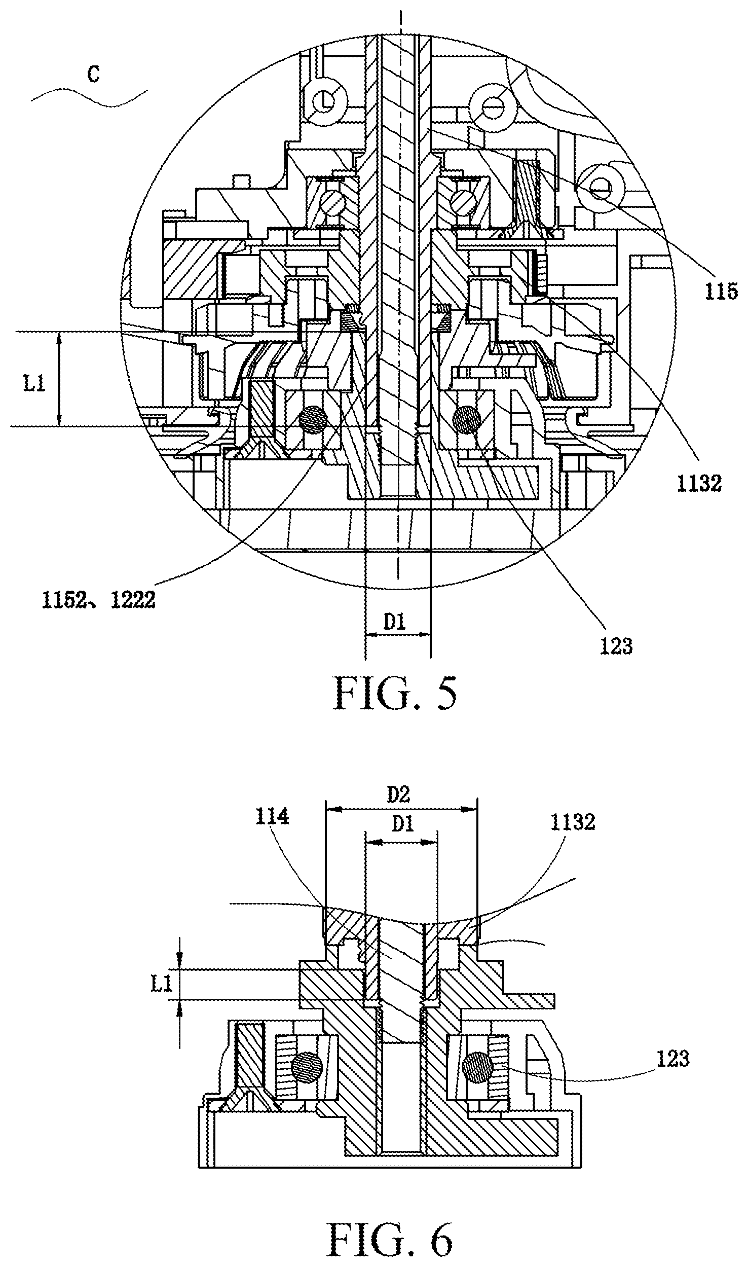
[0065] FIG. 5 is a partially enlarged view of a part C in FIG. 1.
[0066] FIG. 6 is a schematic diagram of an input assembly abutting against a large end face according to the first implementation of the present invention.
[0067] FIG. 7 is a partially enlarged view of a part B in FIG. 1 of the present invention.
[0068] FIG. 8 is a schematic diagram of an internal air-duct direction of a grinding tool according to the first implementation of the present invention.
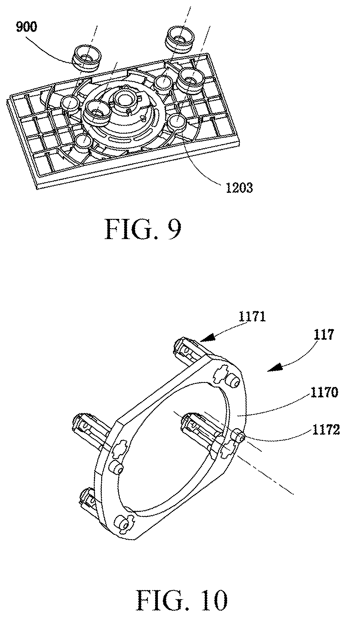
[0069] FIG. 9 is a schematic diagram of a positional relationship between a grinding component and an elastic element according to the first implementation of the present invention.
[0070] FIG. 10 is a schematic structural diagram of a limiting mechanism according to the first implementation of the present invention.
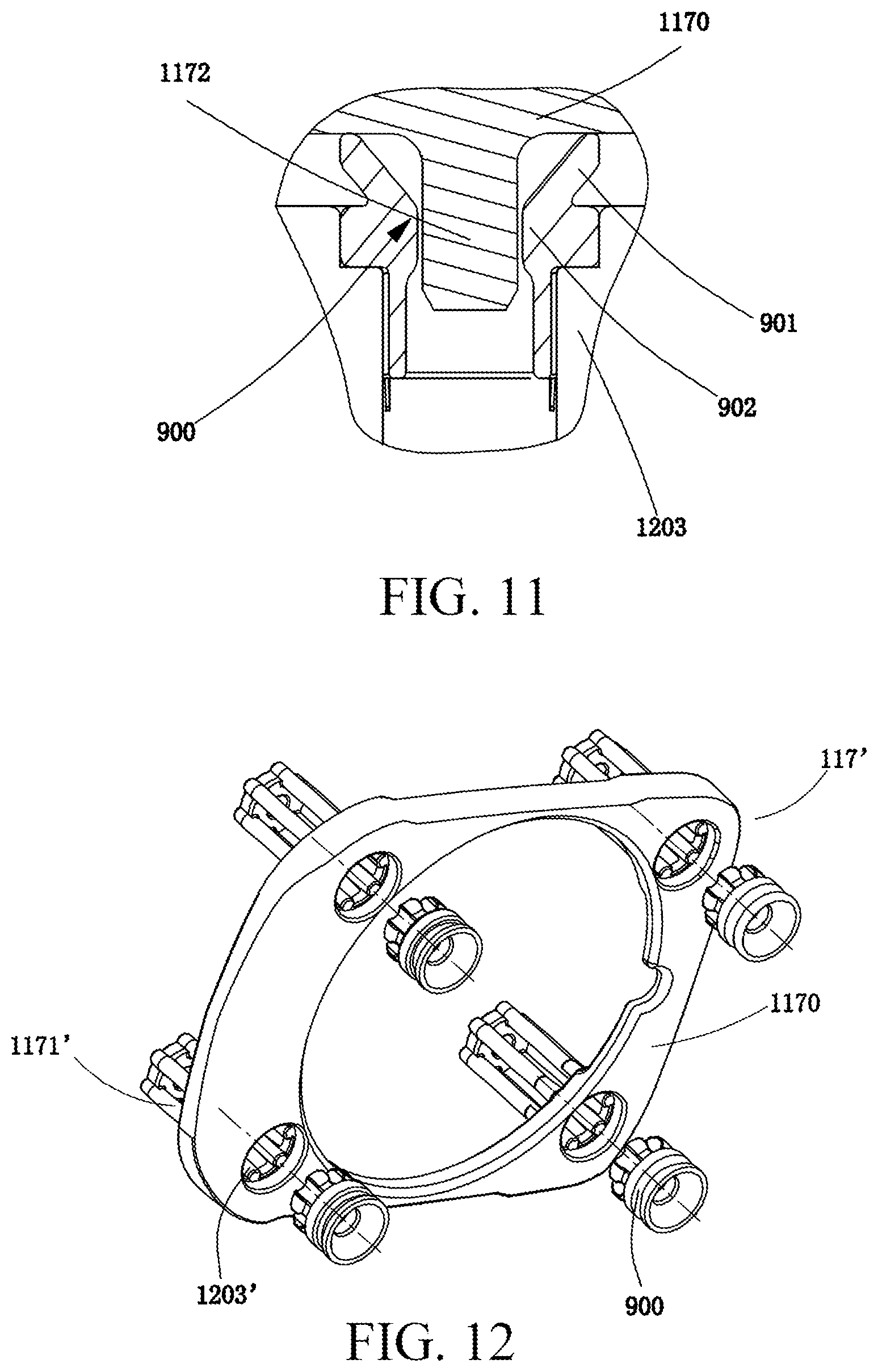
[0071] FIG. 11 is a sectional view of a joint position between a limiting post and a limiting hole according to the first implementation of the present invention.
[0072] FIG. 12 is a schematic structural diagram of a limiting mechanism according to another implementation of the present invention.
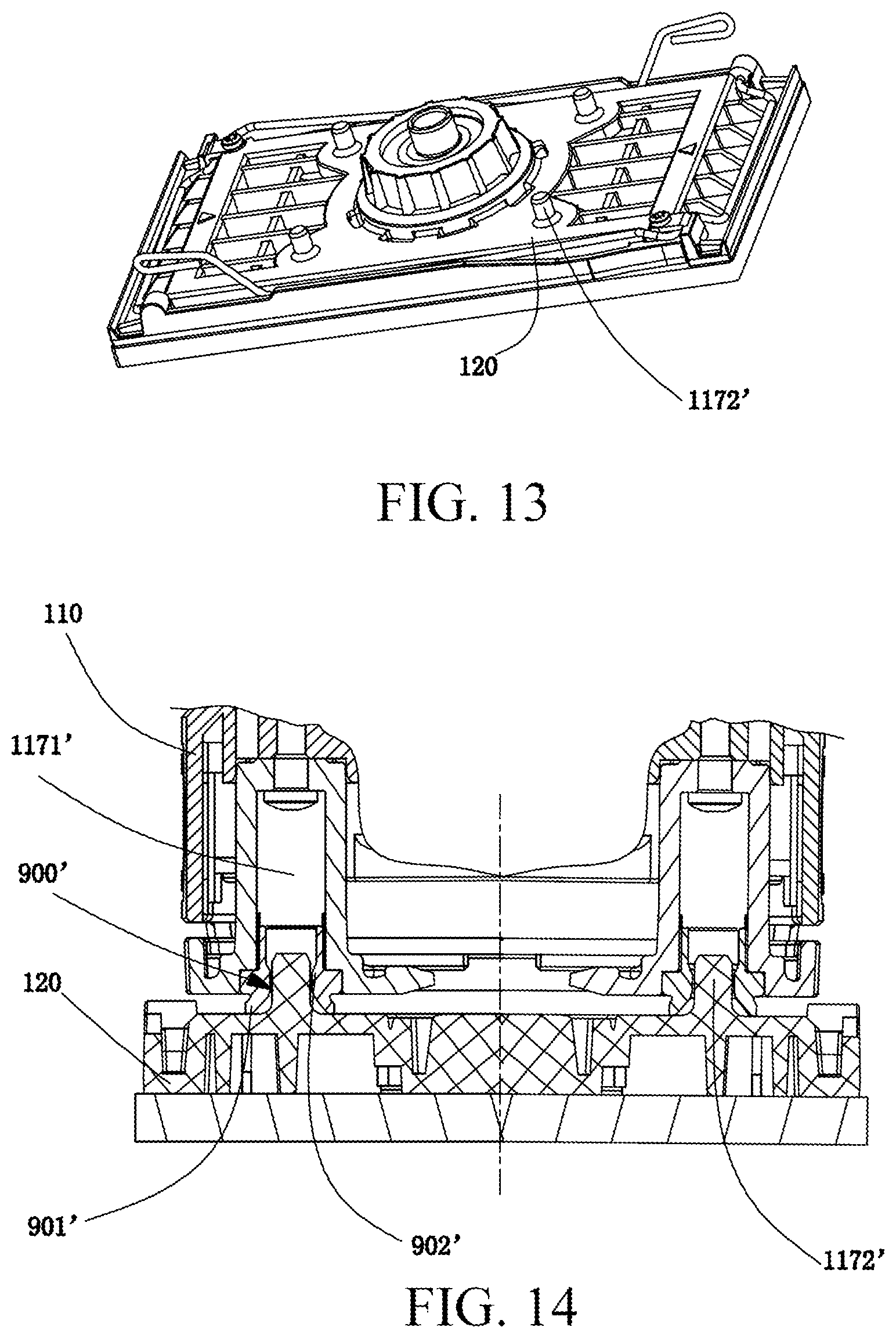
[0073] FIG. 13 is a schematic diagram of a grinding component that is joined to a limiting mechanism according to another implementation of the present invention.
[0074] FIG. 14 is a partial sectional view of a grinding component being joined to a limiting mechanism according to another implementation of the present invention.
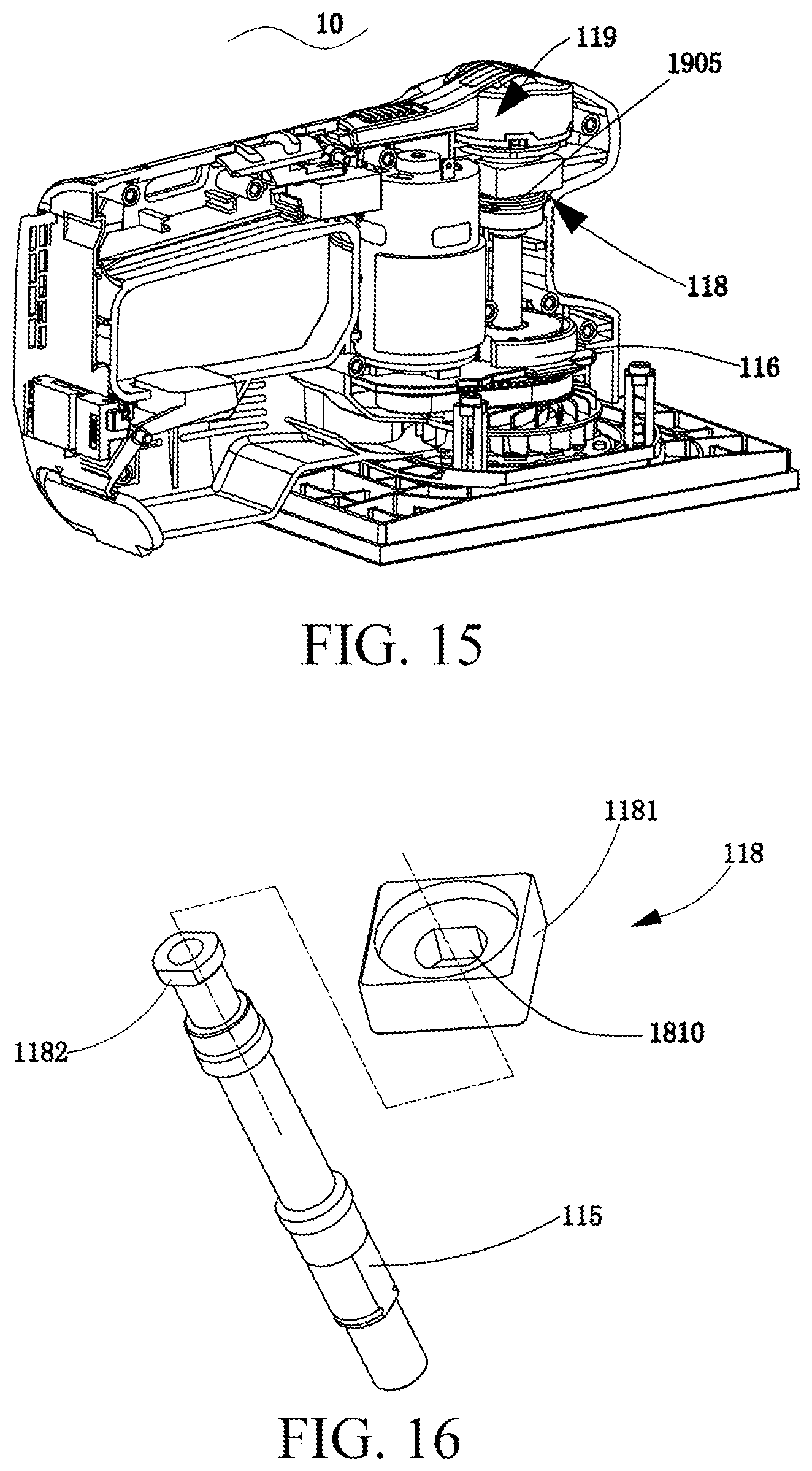
[0075] FIG. 15 is a schematic diagram of an internal structure of a grinding tool according to the first implementation of the present invention.
[0076] FIG. 16 is a schematic diagram of a locking mechanism according to the first implementation of the present invention.
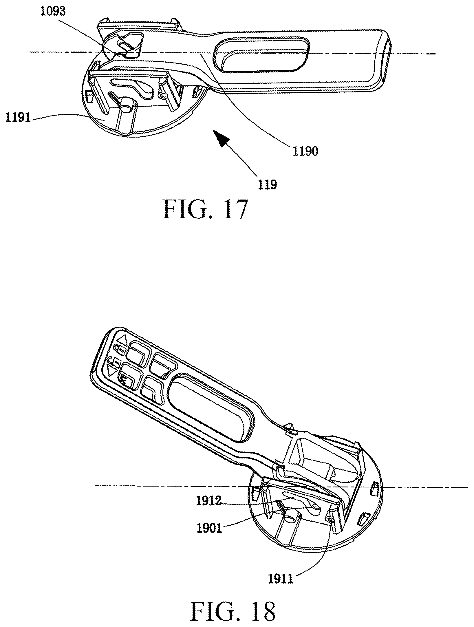
[0077] FIG. 17 is a schematic diagram of an operating mechanism when an operating member is in a closed state according to the present invention.
[0078] FIG. 18 is a schematic diagram of an operating mechanism when an operating member is in an operating state according to the present invention.
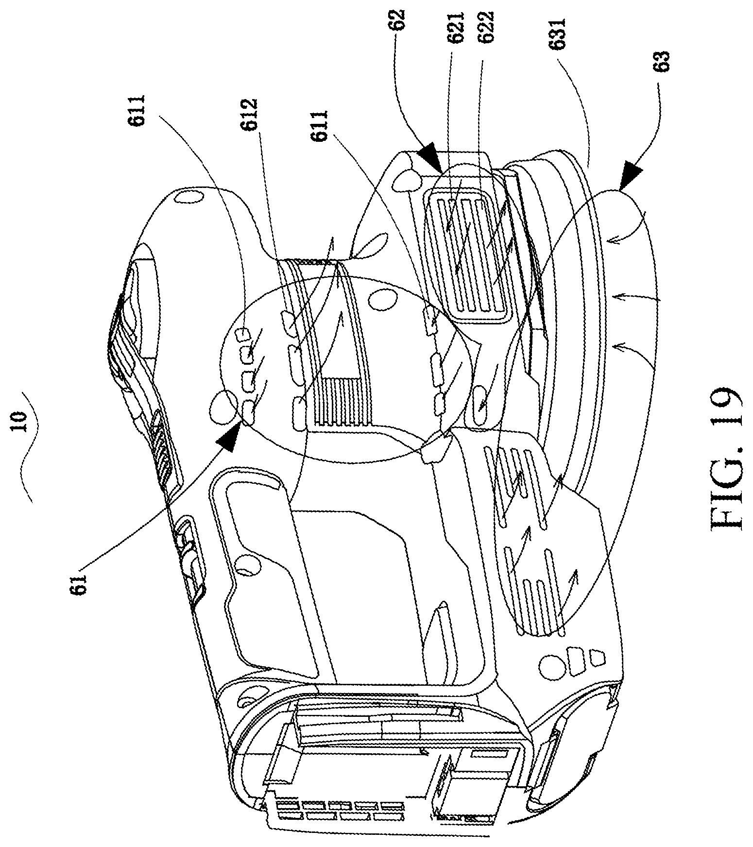
[0079] FIG. 19 is a schematic diagram of an external wind direction of a grinding tool according to the first implementation of the present invention.
[0080] FIG. 20 is a schematic diagram of an external wind direction of a grinding tool according to a second implementation of the present invention.
[0081] FIG. 21 is a schematic diagram of an internal air-duct direction of a grinding tool according to the second implementation of the present invention.
[0082] FIG. 22 is a sectional view of a main component being not joined to a grinding component of a grinding tool according to the second implementation of the present invention.
[0083] FIG. 23 is a sectional view of a main component being joined to a grinding component of a grinding tool according to the second implementation of the present invention.
[0084] FIG. 24 is a partially enlarged view of a part D in FIG. 22.
[0085] FIG. 25 is a schematic structural diagram of a locking mechanism according to the second implementation of the present invention.
[0086] FIG. 26 is a schematic structural diagram of a locking mechanism being in a locked state in a grinding tool according to a third implementation of the present invention.
[0087] FIG. 27 is a schematic structural diagram of a locking mechanism being in an unlocked state in a grinding tool according to the third implementation of the present invention.
[0088] FIG. 28 is a schematic diagram of a main component being not joined to a grinding component of a grinding tool according to a fourth implementation of the present invention.
[0089] FIG. 29 is a sectional view taken along a direction F-F in FIG. 28.
[0090] FIG. 30 is a sectional view of a locking mechanism being in an unlocked state according to a fifth implementation of the present invention.
[0091] FIG. 31 is a sectional view of a locking mechanism being in a locked state according to the fifth implementation of the present invention.
[0092] FIG. 32 is a sectional view of an operating member being disconnected from a first connecting member according to a sixth implementation of the present invention.
[0093] FIG. 33 is a sectional view of an operating member being connected to a first connecting member according to the sixth implementation of the present invention.
DETAILED DESCRIPTION
[0094] The following will describe some exemplary embodiments more fully with reference to the accompanying drawings. The same reference numerals indicate the same components throughout the accompanying drawings.
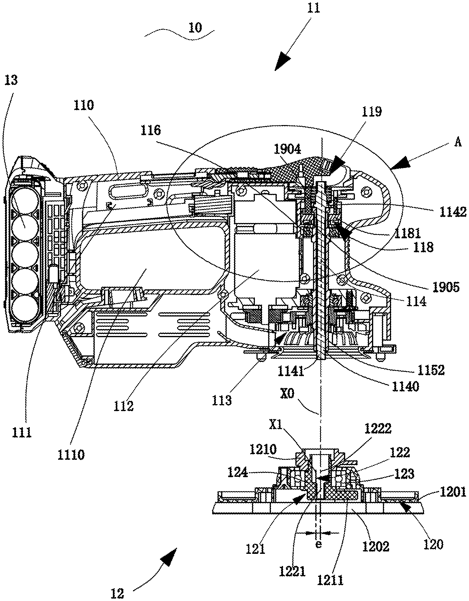
[0095] Referring to FIG. 1 to FIG. 3, the reference numeral 10 indicates a general and exemplary handheld tool. A grinder 10 is used as an exemplary handheld power tool for description below. The grinder 10 includes a main component 11 and a grinding component 12. The main component 11 includes a housing 110, a motor 112 disposed inside the housing 110, and an output assembly 113 driven by the motor 112 to rotate. The grinding component 12 includes a grinding body 120 and an input assembly 121 located on the grinding body 120. A side, facing a to-be-treated working surface, of the grinding body 120 may be equipped with a sanding element (for example, sandpaper). The input assembly 121 can be driven by the output assembly 113 to rotate relative to the grinding body 120, to drive the grinding body 120 to work. To implement the inseparable connection between the grinding component 12 and the main component 11 in the axial direction of the motor 112, the main component 11 further includes a first connecting member 114. The grinding component 12 includes a second connecting member 122 that cooperates with the first connecting member 114. When the first connecting member 114 is joined to the second connecting member 122 to make the grinding component 12 inseparably connected to the main component 11 in the axial direction of the motor 112, the first connecting member 114 and the second connecting member 122 may rotate with the input assembly 121. For a reliable and stable connection between the first connecting member 114 and the second connecting member 122, preferably, the first connecting member 114 and the second connecting member 122 connects to each other through thread.
[0096] In this embodiment, the output assembly 113 includes a first driving wheel 1131 disposed coaxially with the motor 112 and driven by the motor 112 to rotate, and a second driving wheel 1132 driven by the first driving wheel 1131 and having a pivot axis spaced from that of the first driving wheel 1131. To reduce the noise and vibration generated by the first driving wheel 1131 and the second driving wheel 1132 during torque transmission, preferably, a transmission belt is used to transfer power between the first driving wheel 1131 and the second driving wheel 1132. In this embodiment, for a better support of the second driving wheel 1132, the main component 11 further includes a connecting shaft 115 disposed inside the housing 110, and the second driving wheel 1132 is sleeved on an outer side of the connecting shaft 115 to enable the connecting shaft 115 to support the second driving wheel 1132. In this embodiment, the second driving wheel 1132 is fixedly sleeved on an outer side of the connecting shaft 115 to drive the connecting shaft 115 to rotate, and the connecting shaft 115 is rotatably disposed on the housing 110 through a support bearing 116. It can be understood that, in other embodiments, the connecting shaft 115 may be fixedly connected to the housing 110, that is, may be non-rotatably fixed to the housing 110, and the second driving wheel 1132 is disposed to be rotatably connected to the connecting shaft 115 to enable the connecting shaft 115 to support the second driving wheel 1132. To transfer the output torque of the output assembly 113 to the input assembly 121, preferably, the output assembly 113 further includes an output portion 1133 fixedly connected to the second driving wheel 1132, and the input assembly 121 includes an input portion 1210 that can cooperates with the output portion 1133. In one embodiment, one of the output portion 1133 and the input portion 1210 includes a plurality of male splines, the other one includes a plurality of female splines that receive the male splines. In other embodiments, the output portion 1133 and the input portion 1210 may be disposed to have other forms that can transfer torque, for example, each of the output portion 1133 and the input portion 1210 having a rectangular cross section. The output assembly 113 transfers torque to the input assembly 121 to drive the input assembly 121 to rotate relative to the grinding body 120.
[0097] It can be understood that, in other embodiments, the output portion 1133 may be disposed on an outer side of the connecting shaft 115, the second driving wheel 1132 drives the connecting shaft 115 to rotate, and the connecting shaft 115 then drives the output portion 1133 to rotate. That is, the connecting shaft 115, as a part of the output assembly 113, is used as a drive shaft for driving the output portion 1133.
[0098] Continue to refer to FIG. 1. The input assembly 121 is at least partially disposed to be an eccentric element 124 in an axial direction, and the central axis X1 of the eccentric element 124 is spaced from the pivot axis X0 of the input assembly 121, that is, there is an eccentric distance e between the central axis X1 and the pivot axis X0 of the eccentric element 124. The grinding body 120 includes a plate body 1202 used to mount sandpaper and a cover body 1201 fixedly connected to the plate body 1202. The cover body 1201 is disposed on an outer side of the eccentric element 124 by a mounting bearing 123, so that the eccentric element 124 rotates to drive the grinding body 120 to move. It can be easily understood that, because the pivot axis X0 (that is, the pivot axis X0 of the input assembly) of the eccentric element 124 is spaced from the central axis X1 of the eccentric element 124, that is, the mass of the eccentric element 124 is asymmetrically distributed relative to its pivot axis X0, the eccentric element 124 tends to shake during rotation. To compensate for the mass imbalance of the eccentric element 124 during rotation relative to its pivot axis X0, the input assembly 121 further includes a counterbalance 1211. The central axis of the eccentric element 124 is located on one side of the pivot axis X0 of the input assembly, and the counterbalance 1211 is located on the other side, opposite to the central axis, of the pivot axis X0. It can be understood that, the grinding components 12 with different shapes of plate body 1202, for example, a grinding component 12 with a circular plate body 1202, a grinding component 12 with a non-circular plate body 1202, they have different eccentric distances e due to different working conditions. Therefore, the mass of the counterbalance 1211 required for compensating for the eccentric element 124 of different grinding components also varies. In this embodiment, the counterbalance 1211 is disposed in the sanding component, so that different grinding component (for example, a sanding component with a circular plate body, or a grinding component with a non-circular plate body) can have independent counterbalances 1211, to achieve the optimal vibration reduction effect. It can be understood that, the counterbalance 1211 may be disposed below the mounting bearing 123 or may be located above the mounting bearing 123 or may be located both below and above the mounting bearing 123.
[0099] Referring to FIG. 1, FIG. 2, FIG. 5, and FIG. 6, in this embodiment, the first connecting member 114 includes a first joining portion 1141 that is located below the first connecting member 114 and is used to be connected to the second connecting member 122. Preferably, the first joining portion 1141 is provided with an external thread 1140, and the second connecting member 122 includes a second joining portion 1221 joined to the first joining portion 1141. Preferably, the second joining portion 1221 is disposed to be a mounting hole that can accommodate the first joining portion 1141. At least part of the inner circumferential surface of the mounting hole is provided with an internal thread 1220 that matches the external thread 1140. In this embodiment, the connecting shaft 115 is a hollow shaft, the first connecting member 114 is located at least partially within the hollow shaft 115, and to prevent the first connecting member 114 from falling out of the hollow shaft, the upper end of the first connecting member 114 is provided with a flange 1142. In this embodiment, to ensure the coaxiality of the main component 11 and the grinding component 12, that is, the coaxiality of the first connecting member 114 and the pivot axis of the input assembly 121, and the coaxiality of the connecting shaft 115 to reduce the vibration of the grinder 10 at work, the second connecting member 122 further includes a second support portion 1222. Preferably, the second support portion 1222 is disposed to be a groove extending in the pivot axis direction, and a first support portion 1152 used to protrude into the groove having an outer diameter substantially the same as that of the groove of the second support portion is formed below the connecting shaft 115. A length of the connecting shaft 115 extending into the mounting hole is L1, that is, the axial size of the first support portion 1152 is L1, and L1 ranges from 4 mm to 30 mm. Preferably, L1 ranges from 11.25 mm to 13.75 mm. More preferably, L1 is 12.5 mm. The first support portion 1152 and the second support portion 1222 (the groove) are joined to each other with little spacing, that is, an outer diameter of the first support portion 1152 is substantially the same as that of the second support portion 1222 (the groove), and the outer diameter is referred to as a joining diameter D1 for short below. The joining diameter D1 ranges from 7 mm to 12 mm. Preferably, the joining diameter D1 ranges from 8.55 mm to 10.45 mm. More preferably, the joining diameter D1 is 9.5 mm.
[0100] It can be easily understood that, in a case that the joining diameter D1 is a specific value, if the joining length L1 is larger, the joining effect is better, that is, the coaxiality is better. However, if L1 is greater, the entire machine is higher. Referring to FIG. 6, in this embodiment, to ensure the desirable coaxiality of the entire machine when the joining length is smaller, the main component 11 is provided with an abutting end face that abuts against an upper end face of the input assembly 121, and a diameter D2 of the abutting end face is greater than D1. In this embodiment, the abutting end face is an end face on which the second driving wheel 1132 abuts against the input assembly 121. It can be understood that, in other embodiments, the abutting end face may be an end face that is fixedly connected to the second driving wheel 1132 and abuts against the input assembly 121. In this embodiment, a large end face is used for abutting, and when a ratio of the joining length L1 to the joining diameter D1 is as small as 0.33, it can be ensured that the joining length L1 is short when D1 is a specific value. Certainly, it can be understood that, while ensuring the large end face, if the ratio of L1/D1 is greater, the coaxiality is more stable.
[0101] In this embodiment, the grinding component 12 may be a circular grinding component with a circular plate body, as shown in FIG. 1, FIG. 2, and FIG. 8, and the grinding component 12 may be a noncircular grinding component with a non-circular plate body (e.g. a rectangular plate body), grinding component as shown in FIG. 9, FIG. 13, and FIG. 15. An operator may choose the circular grinding component or the noncircular grinding component grinding component to be joined to the main component 11 according to different grinding requirements. During grinding, the grinding body 120 of the circular grinding component not only makes an eccentric swinging, but also makes a rotation under the action of the eccentric element 124 due to the mounting bearing 123. That is, the grinding body 120 of the circular grinding component makes an orbital movement including a revolution and a rotation. Therefore, when the operator needs to remove a large amount of sanding material, the operator may mount the circular grinding component to the main component 11. In this embodiment, the noncircular grinding components may have a grinding plate with a rectangular shape, the size of the grinding plate with the rectangular shape is substantially the same as one third of the standard sandpaper specification (a size of 228 mm.times.280 mm) well known in the grinding field. So we also call the grinding component with this kind of grinding plate one-third grinding component. The noncircular grinding components may have a grinding plate with a foursquare shape, the size of the grinding plate with the foursquare shape is substantially the same as a quarter of the standard sandpaper specification (a size of 228 mm.times.280 mm) well known in the grinding field. So we also call the grinding component with this kind of grinding plate quarter grinding component. The noncircular grinding component fixes the sandpaper to its plate body 1202 through an elastic clamping member, and the circular grinding component fixes the sandpaper to the plate body by using felt or other manners. Certainly, it can be understood that noncircular grinding component may fix the sandpaper by using felt or other manners.
[0102] It should be noted that, the noncircular plate body 1202 of the noncircular grinding component (e.g. one-third grinding component or quarter grinding component) has sharp edges. If the plate body 1202 of a grinding component makes both a revolution and a rotation under the action of the input assembly 121, four edges of the plate body 1202 that rotates at high speed are prone to cause danger. Therefore, the grinder 10 further includes a limiting mechanism 117 used for limiting the rotation of the plate body.
[0103] Referring to FIG. 9 to FIG. 14, the limiting mechanism 117 includes a limiting substrate 1170 and a limiting foot 1171 disposed on the limiting substrate 1170. In this embodiment, each limiting foot 1171 includes a plurality of flexible posts. Preferably, the number of the flexible posts is an even number. More preferably, the number of the flexible post is 4 or 6. In this embodiment, the limiting mechanism 117 is located in the main component 11. Therefore, a limiting structure does not need to be separately disposed for each noncircular grinding component or other grinding component of which the rotation is needed to be limited. An upper end of the limiting foot 1171 is detachably fixed to the housing 110, so that the limiting foot 1171 can be replaced after being damaged due to deformation under a long-time stress. Preferably, the upper end of the limiting foot 1171 is connected to the housing by a screw, so that the limiting foot 1171 can be stably fixed to the housing 110 and is not prone to freely fall off the housing 110. Referring to FIG. 2, because the upper end of the limiting mechanism 117 is covered by the housing 110, that is, the upper end of the limiting foot 1171 is not exposed to the outside of the housing 110, and a lower end of the limiting mechanism 117 is blocked by the limiting substrate 1170, tools such as a screwdriver cannot reach the interior of the housing 110, causing difficulty in the mounting of the limiting mechanism 117. In this embodiment, the plurality of flexible posts of each limiting foot 1171 are arranged circumferentially to form a hollow through-hole and the hollow-through hole penetrates the limiting substrate 1170, so that the operator can screw in the screw through the through-hole from the bottom of the substrate 1170. A side, away from the limiting foot 1171, of the limiting substrate 1170 is provided with a limiting post 1172, and the grinding body 120 of the grinding component is provided with a limiting hole 1203 to be joined to the limiting post 1172, to limit the rotation of the grinding body of the grinding component. Preferably, an elastic element 900 is disposed between the limiting hole 1203 and the limiting post 1172. Referring to FIG. 11, the elastic element 900 includes a first elastic member 901 that is located between the substrate 1170 and the opening of the limiting hole 1203 and is used to isolate the vibrations of the limiting hole 1203 and the limiting mechanism 117 in the vertical direction, that is, to isolate the vibration between the grinding body 120 and the limiting mechanism 117 in the vertical direction or the axial direction. The elastic element 900 further includes a second elastic element 902 that is located between the limiting post 1172 and a side wall of the limiting hole 1203 and is used to isolate the vibrations of the limiting post 1172 and the limiting hole 1203 in the radial direction, that is, to isolate the vibration between the grinding body 120 and the limiting mechanism 117 in the radial direction. Referring to FIG. 9, in this embodiment, because the grinding component 12 of the grinder 10 may vary (e.g. the circular grinding component or the non-circular grinding component). Except for the one-third grinding component and the quarter grinding component, the plate body of the grinding component needs the limiting mechanism 117, further includes another grinding component of which the plate body (also referred to as mouse sandpaper) is approximately iron-shaped. When each plate body is provided with four elastic elements, a larger quantity of elastic elements are required, leading to higher costs. In addition, because the fit between the elastic element 900 and the limiting hole 1203 is mostly an interference fit, it is relatively difficult to mount the elastic element 900 into the limiting hole 1203. Therefore, if the quantity of the elastic element 900 to be mounted is larger, the assembly is more difficult.
[0104] Referring to FIG. 12 to FIG. 14, the present invention further provides a limiting mechanism 117' having another structure. Same as the limiting mechanism 117 in the above embodiment, the limiting mechanism 117' includes a limiting substrate 1170' and a limiting foot 1171' disposed on the limiting substrate 1170', each limiting foot 1171' includes a plurality of flexible posts, the limiting mechanism 117' is detachably fixed to the housing 110 of the main component 11 by a screw, and the plurality of flexible posts of each limiting foot 1171' are arranged circumferentially to form a hollow through-hole and the through-hole penetrates the limiting substrate 1170'. A difference from the above embodiment is that, in this embodiment, a limiting post 1172' is disposed in the plate body, the hollow through-hole formed by the plurality of flexible posts of the limiting foot 1171' is a limiting hole 1203', and an elastic element 900' is disposed at an end, close to the limiting substrate 1170', of the hollow through hole. Referring to FIG. 14, similar to the structure of the elastic element 900 in the above embodiment, the elastic element 900' in this embodiment includes a first elastic member 901' that is located between the grinding body 120 and an opening of the limiting hole 1203' and is used to isolate the vibrations of the grinding body 120 and the limiting mechanism 117' in the vertical direction. The elastic element 900' further includes a second elastic element 902' that is located between the limiting post 1172' and a side wall of the limiting hole 1203' and is used to isolate the vibrations of the limiting post 1172' and the limiting hole 1203' in the radial direction, that is, to isolate the vibration between the grinding body 120 and the limiting mechanism 117' in the radial direction.
[0105] Referring to FIG. 1, when the grinding component 12 is connected to the main component 11 or is detached from the main component 11, the first connecting member 114 is required to rotate relative to the second connecting member 122. However, it can be learned from the above description of the structure of the main component 11 and the grinding component 12 that, when the first connecting member 114 rotates under the operation, the external thread 1140 of the first joining portion 1141 interacts with the internal thread 1220 of the second joining portion 1221, to enable the input assembly 121 to rotate together. The input assembly 121 further drives the output assembly 113 and the connecting shaft 115 to rotate through the input portion 1210 and the output portion 1133. As a result, a threaded rod 1140 and the mounting hole cannot rotate relative to each other, and the external thread 1140 of the first joining portion 1141 and the internal thread 1220 of the second joining portion 1221 cannot be tightened or loosened. Referring to FIG. 1, FIG. 15, and FIG. 16, the grinder 10 in the present invention further includes a locking mechanism 118, and the locking mechanism 118 can implement the circumferential locking of the input assembly 121 to enable the first connecting member 114 to rotate relative to the second connecting member 122. Preferably, the locking mechanism 118 is disposed in the main component 11. The locking mechanism 118 has a locked state and an unlocked state. When the locking mechanism 118 is in the locked state, the locking mechanism 118 circumferentially locks the input assembly 121, that is, the input assembly 121 cannot rotate relative to the housing 110. When the locking mechanism 118 is in the unlocked state, the locking mechanism 118 releases the circumferential locking of the input assembly 121, that is, the input assembly 121 can rotate relative to the housing 110.
[0106] Referring to FIG. 1 and FIG. 16, in this embodiment, to facilitate to lock the input assembly 121, the locking mechanism 118 circumferentially locks the input assembly 121 by circumferentially locking the connecting shaft 115. The locking mechanism 118 includes a first locking member 1181 movable relative to the housing 110 but non-rotatable and a second locking member 1182 that is fixedly connected to or integrally disposed with the connecting shaft 115. The first locking member 1181 can move between a first position and a second position. When the first locking member 1181 is in the first position, the first locking member 1181 is joined to the second locking member 1182, that is, the locking mechanism 118 is in the locked state, and the connecting shaft 115 is circumferentially locked. In this embodiment, it can be learned from the above description that, because the second driving wheel 1132 is fixedly sleeved on an outer side of the connecting shaft 115 to drive the connecting shaft 115 to rotate, that is, the connecting shaft 115 and the output assembly 113 are connected to each other while cannot rotate relative to each other, when the connecting shaft 115 is locked, the output assembly 113 is also locked and cannot rotate in the circumferential direction. In addition, because the output assembly 113 and the input assembly 121 mesh with each other and transfer torque through the ratchets, that is, the output assembly 113 and the input assembly 121 cannot rotate relative to each other in the circumferential direction. Therefore, when the connecting shaft 115 is locked, the input assembly 121 is also circumferentially locked, so that the first connecting member 114 operably rotates relative to the second connecting member 122. When the first locking member 1181 is in the second position, the first locking member 1181 is detached from the second locking member 1182, that is, the locking mechanism 118 is in the unlocked state, the locking mechanism 118 releases the circumferential locking of the connecting shaft 115, and the connecting shaft 115 can rotate relative to the housing 110.
[0107] Preferably, the first locking member 1181 is a locking block provided with a flat square hole 1810, the second locking member 1182 is a flat square shaft segment having an outer shape corresponding to that of the flat square hole, and the first locking member 1181 can move between the first position and the second position in the axial direction of the connecting shaft 115. Referring to FIG. 4, when the first locking member 1181 moves upward from the second position to the first position, the flat square hole 1810 of the locking block is joined to the flat square shaft segment, and the input assembly 121 is circumferentially locked. Referring to FIG. 3, when the first locking member 1181 moves downward from the first position to the second position, the flat square hole of the first locking member 1181 is separate from the flat square shaft segment and sleeved on an outer side of the connecting shaft 115. Because the smallest diameter of the flat square hole is greater than the outer diameter of the connecting shaft 115, the connecting shaft 115 can rotate freely in the circumferential direction. It can be understood that, the first locking member 1181 may be a locking block provided with another special-shaped hole, for example, a rhombic, triangular, hexagon or other irregular-shaped hole, and the second locking member 1182 is disposed to be a special-shaped shaft segment having a shape corresponding to the above special-shaped hole. Details are not described herein again.
[0108] Preferably, referring to FIG. 17 and FIG. 18, to facilitate to mounte the grinding component 12 to the main component 11 by operating the first connecting member 114, the main component 11 further includes an operating mechanism 119, the operating mechanism 119 includes an operating member 1190 for the operator to hold and a seat 1191, and the operating member 1190 is pivotally disposed on the seat 1191 by a pivot shaft to switch between a first operation position and a second operation position. Preferably, the pivot axis includes a first pivot shaft 1901 fixed to the operating member 1190 and a second pivot axis 1911 fixed to the seat 1191, the seat 1191 is provided with a first chute 1912 for the first pivot shaft 1901 to rotate, and the operating member 1190 is provided with a second chute (not shown) for the second pivot axis 1911 to move.
[0109] Referring to FIG. 1, FIG. 3, FIG. 4, FIG. 17, and FIG. 18, the operating member 1190 can switch between the first position (referring to FIG. 1 and FIG. 17) in the closed state and the second position in the open state. It should be noted that, the operating member at least partially protrudes from the housing when being in the first position, and the operating member does not protrude from an outer contour of the housing when being in the second position. That is, when the operating member is in the first position, the operating member 1190 and a holding handle 111 are substantially on the same horizontal line. When the operating member is in the second position, the operating member 1190 and the holding handle 111 are placed at an angle. The operating mechanism 119 further includes an abutting member 1904 located between the operating member 1190 and the first locking member 1181, and the locking mechanism 118 further includes a first elastic element 1905 located below the first locking member 1181. Referring to FIG. 3, when the operating member 1190 is in the closed state, the operating member 1190 abuts against the abutting member 1904 downward, and the abutting member 1904 further abuts against the first elastic element 1905 through the first locking member 1181, so that the first elastic element 1905 is compressed, and the first locking member 1181 is in the second position lower to the first position. In this case, the connecting shaft 115 can be driven by the motor 112 to rotate along with the input assembly 121 after a power switch 1120 is started. When the operating member 1190 moves from the closed state shown in FIG. 17 to the open state (not shown in the figure) under the action of the first elastic element 1905, the abutting member 1904 and the first locking member 1181 move upward under the action of the first elastic element 1905 until the first locking member 1181 moves upward to the first position, so that the flat square hole 1810 of the locking block is joined to the flat square shaft segment, and the connecting shaft 115 is circumferentially locked, that is, the input assembly 121 is circumferentially locked.
[0110] In this embodiment, to facilitate the operation of the first connecting member 114 and to keep the structure of the grinder 10 simple, the operating member 1190 may further be used to drive the first connecting member 114 to rotate. After the operating member 1190 is in the open state, when the operating member 1190, is in the first operation position, the operating member 1190 still cannot drive the first connecting member 114 to rotate. When the operating member 1190 rotates from the first operation position to the second operation position around the pivot axis, the operating member 1190 can drive the first connecting member 114 to rotate around its axis (that is, the axis of the input assembly 121). In this embodiment, the first connecting member is provided with a transmission element. Referring to FIG. 3 and FIG. 4, in this embodiment, the transmission element is a second convex lug 1401 disposed on the first connecting member 114, and the operating member includes a first convex lug 1903 corresponding to the second convex lug 1401. When the operating member 1190 is in a second operating state, the first convex lug 1903 is joined to the second convex lug 1401, so that the operating member 1190 can drive the seat 1191 and the first connecting member 114 to rotate relative to the housing 110, to enable the grinding component 12 to be connected to or detached from the main component 11.
[0111] Referring to FIG. 4, to facilitate to hold, the main component 11 further includes a holding handle 111 for holding, and a groove 1110 is disposed below the holding handle 111 for fingers to bend in during holding. In addition, the common end away from the motor of the holding handle 111 and the groove 1110 is provided with a power supply unit. Preferably, in this embodiment, the power supply unit is a battery pack 13, and the battery pack 13 is detachably connected to the housing 110. It can be understood that, in other embodiments, the power supply unit may be an alternating current power supply unit.
[0112] Referring to FIG. 19, the grinder 10 further includes two cooling portions and a dust guiding portion 63, and the two cooling portions are a first cooling portion 61 and a second cooling portion 62. Each of the two cooling portions and the dust guiding portion includes a fan disposed in the housing 110, an air inlet, and an air outlet. That is, the first cooling portion 61 includes a first fan 610 (referring to FIG. 4), a first air inlet 611, and a first air outlet 612. The second cooling portion 62 includes a second fan 620, a second air inlet 621, and a second air outlet 622. The dust guiding portion 63 includes a third fan 630, a third air inlet 631, and a third air outlet 632. The first fan 610 is a centrifugal fan located at the top end of the motor 112 away from the grinding component 12. The first air inlet 611 is located at two ends of the motor, both close to the grinding component 12 and away from the grinding component 12. That is, the first air inlet 611 is distributed in the axial direction of the motor 112. The first air outlet 612 is in an area corresponding to the first fan 610, that is, located between two air inlets of the motor 112. In this embodiment, preferably, the first fan 610 is located above the stator and the rotor of the motor 112. An airflow entering from the first air inlet 611 near the end of the grinding component 12 flows through the stator and the rotor of the motor under the action of the first fan 610, then flows out of the first air outlet 612. An airflow enters from a first air inlet away from an end of the grinding component 12, flows through an inverter (located above the fan) in the motor 112, and then flows out of the first air outlet 612. Therefore, the first cooling portion 61 can take away heat generated from the motor 112 to implement cooling of the motor 112. In this embodiment, the second fan 620 is fixedly connected to the second driving wheel 1132 and is driven by the second driving wheel 1132 to rotate, and the second fan 620 is located below the second driving wheel 1132 to cool the second driving wheel 1132, the transmission belt located between the first driving wheel 1131 and the second driving wheel 1132, and so on. The second air inlet 621 and the second air outlet 622 are located in an area on the housing 110 corresponding to the second fan 620 in the housing 110. Preferably, the second air inlet 621 and the second air outlet 622 are disposed in a vertical direction on the housing 110 in an area corresponding to the second fan 620. The third fan 630 is located above the grinding component 12 and is disposed tightly close to the upper end of the grinding component 12. Preferably, as shown in FIG. 4, the third fan 630 and the second fan 620 share the same wheel hub. In other words, the second fan 620 is provided above the wheel hub, and the third fan 630 is provided below the wheel hub. The third air inlet 631 is located on a side surface of the plate body 120 facing sandpaper and the third air inlet 631 is also on the sandpaper. The third air outlet 632 is a dust collection outlet in communication with the third fan 630, so that debris and dust generated during sanding of the grinding component 12 are blown by the third fan 630 into a dust collection bag or a dust collection box.
[0113] Referring to FIG. 20 to FIG. 23, a grinder 10' (referred to as a second embodiment below) with another structure of the present invention, is the same as the structure of the grinder 10. The grinder 10' includes a main component 11' and a grinding component 12'. The main component 11' includes a housing 110', a motor 112' located in the housing 110', and an output assembly 113' driven by the motor 112' to rotate. The grinding component 12' includes a grinding body 120' and an input assembly 121' partly located in the grinding body 120'. A sanding element (for example, sandpaper) can be mounted on a side, facing the treated surface, of the grinding body 120'. The input assembly 121' can be driven by the output assembly 113' to rotate relative to the grinding body 120', to drive the grinding body 120' to work. To implement the inseparable connection between the grinding component 12' and the main component 11' in the axial direction of the motor, the main component 11' further includes a first connecting member 114', and the grinding component 12' includes a second connecting member 122' which can be matched to the first connecting member 114'. The first connecting member 114' can be driven by the motor 112' to rotate together with the second connecting member 122'. Preferably, for a reliable and stable connection between the first connecting member 114' and the second connecting member 122', preferably, the first connecting member 114' is connected to the second connecting member 122' by a thread. That is, the first connecting member 114' is provided with a first joining portion 1141', and the second connecting member 122' is provided with a second joining portion 1221' which can be matched to the first joining portion 1141'. Preferably, the first joining portion 1141' is provided with an external thread 1140'. Preferably, the second joining portion 1221' is disposed to be a mounting hole that can accommodate to the first joining portion 1141'. At least part of the inner circumferential surface of the mounting hole is provided with an internal thread 1220' that matches the external thread 1140'. In this embodiment, the output assembly 113' includes a first driving wheel 1131' coaxially disposed with the motor 112' and driven by the motor 112' to rotate and a second driving wheel 1132' driven by the first driving wheel 1131' and having a pivot axis spaced from that of the first driving wheel 1131'. The second driving wheel 1132' is supported by a hollow connecting shaft 115' rotatably disposed in the housing 110'. A main difference between the structure of the grinder 10' in this embodiment and the grinder 10 in that embodiment is that the pivot axis of the input assembly 121' in this embodiment is located between the axis of the motor 112' and a battery pack 13'. Because the motor 112' and the battery pack 13' in the grinder 10' are heavier than the other parts of the entire machine, the center of gravity of the entire machine is located between the motor 112' and the battery pack 13'. In this way, the center of gravity of the entire machine can be close to a holding handle 111' and can be close to the pivot axis of the input assembly 121', to facilitate holding and stabilize the output of the entire machine. In addition, as can be known from the foregoing description of the embodiments, the limiting mechanism needs to be disposed at the main component 11' of the grinder 10' to join with the noncircular grinding component. To reduce the vibration of the entire machine during working, a limiting mechanism 117' is needed and the limiting mechanism 117' usually includes a plurality of limiting feet 1171'. In the foregoing embodiment, because the pivot axis of the input assembly 121 is located on a side, away from the holding handle 111, of the motor 112, the length of the entire machine is increased by the limiting feet. In this embodiment, because the pivot axis of the input assembly 121' is located on a side, near the holding handle 111', of the motor 112', the limiting mechanism 117' or the limiting feet 1171' completely move toward the battery pack 13', to help reduce the length of the entire machine.
[0114] In the foregoing embodiments, the cooling of the motor 112 is completely accomplished by the first cooling portion 61 without using the large second fan 620 of the second cooling portion. As a result, the motor 112 is not adequately cooled. To achieve a better cooling effect of the motor 112, this embodiment provides another cooling structure different from the foregoing embodiments. Referring to FIG. 20 and FIG. 21, a cooling portion of the grinder 10' in this embodiment includes a first cooling portion (not shown in the figure) configured to cool the motor 112' and a second cooling portion (not shown in the figure) configured to mainly cool the second driving wheel 1132' and a transmission belt connecting the first driving wheel 1131' and the second driving wheel 1132'. The first cooling portion includes a first fan 610'. The first fan 610' is located below positions at which the stator and the rotor of the motor 112' are located. A second fan 620' is located below the second driving wheel 1132'. In this embodiment, to reduce the length of the grinder 10' in a horizontal direction, the second fan 620' and the first fan 610' are placed in a vertically staggered manner. That is, the first fan 610' and the second fan 620' are not at the same horizontal height. Preferably, the second fan 620' is located below the first fan 610' in a height direction. In this embodiment, the first cooling portion and the second cooling portion share a same air inlet 630' and air outlet 640'. At least part of the air inlet 630' is located above the stator and the rotor of the motor 112', and at least part of the air outlet 640' is located on the housing 110' in an area corresponding to the second fan 620'. The second fan 620' can guide an airflow that is flowing through the first fan 610' to follow out of the air outlet 640'. In this way, the airflow stably enters the housing 110' from the air inlet 630', moves to the first fan 610 through the motor 112', and is then guided by the second fan 620' out of the housing 110'. That is, in this embodiment, the first cooling portion configured to cool the motor 112' is in communication with the second cooling portion configured to mainly cool the second driving wheel 1132'. An airflow enters from the air inlet 630', then enters from the upper end (the end away from the grinding component 12') of the motor 112', flows inside the motor 112', flows out through a lower end (the end near the grinding component 12') of the motor 112', and is then guided by the second fan 620' to flow out of the air outlet 640'. Therefore, the motor 112', the second driving wheel 1132', the transmission belt, and the others near the the second fan 620' are cooled.
[0115] This embodiment further provides a locking mechanism 118' different from the locking mechanism 118 in the foregoing embodiment. Referring to FIG. 24 and FIG. 25, a second locking member 1182' in this embodiment is a flange body fastened on an outer side of the connecting shaft 115'. The flange body is provided with a stop slot 1810'. A first locking member 1181' is a stop block movable in the axial direction. When the stop block moves upward in the axial direction to the first position, at least part of the stop block is located in the stop slot 1810' to limit the circumferential rotation of the connecting shaft 115'. When the stop block moves downward to the second position in the axial direction, the stop block is separate from the stop slot 1810'. The connecting shaft 115' can freely rotate. Certainly, it can be understood that, in other embodiments, the movement direction of the stop block may further be another direction, for example, a radial direction or a direction at another angle from the axial direction. Details are not described herein again. In addition, same as the foregoing embodiment, in this embodiment, an operating member 1190' is used to implement switching of the locking mechanism 118' between the locked state and the unlocked state. Referring to FIG. 24, when the operating member 1190' is in the closed state, the operating member 1190' abuts against the first locking member 1181' (the stop block) in the axial direction. The first locking member 1181' compresses a first elastic element 1905' downward, so that the first locking member 1181' is located at the second position below, the first locking member 1181' is separate from the second locking member 1182', and the locking mechanism 118' is in the unlocked state. When the operating member 1190' is switched from the closed state to the open state, the second locking member 1182' moves upward to the first position under the action of the first elastic element 1905', the stop block is separate from the stop slot 1810', and the locking mechanism 118' is in the locked state.
[0116] FIG. 26 and FIG. 27 show a grinder 10'' (referred to as a third embodiment below) with another structure according to the present invention. The grinder 10'' includes a main component 11'' and a grinding component 12''. The main component 11'' includes a housing 110'', a motor 112'' located in the housing 110'', and an output assembly 113'' driven by the motor 112'' to rotate. A grinding component 12'' includes a body 120'' and an input assembly 121'' at least partially located in the grinding body 120''. A sanding element (for example, sandpaper) can be mounted on a side, facing the working surface, of the grinding body 120''. The input assembly 121'' can be driven by the output assembly 113'' to rotate relative to the grinding body 120'', to drive the grinding body 120'' to work. To implement the inseparable connection between the grinding component 12'' and the main component 11'' in an axial direction of the motor, the main component 11'' further includes a first connecting member 114''. The grinding component 12'' includes a second connecting member 122'' which can be matched to the first connecting member 114''. The first connecting member 114'' can be driven by the motor 112'' to rotate together with the second connecting member 122''. Preferably, for a reliable and stable connection between the first connecting member 114'' and the second connecting member 122''. Preferably, the first connecting member 114'' and the second connecting member 122'' are connected by a thread. In this embodiment, the output assembly 113'' includes an output shaft 1135'' fixedly connected to the motor 112'' and coaxially driven by the motor to rotate. The first connecting member 114'' includes an external thread 1140'' disposed on a circumference thereof. The first connecting member 114'' is coaxially and fixedly connected to the output shaft 1135'' and being driven by the output shaft 1135'' to rotate. Preferably, the first connecting member 114'' is integrally formed with the output shaft 1135''. The first connecting member 114'' includes a first joining portion located below the first connecting member 114'' and configured to connect to the second connecting member 122''. Preferably, a first joining portion 1141'' is provided with the external thread 1140''. The second connecting member 122'' includes a second joining portion 1221'' joined to the first joining portion 1141''. Preferably, the second joining portion 1221'' is disposed to be a mounting hole that can accommodate the first joining portion 1141''. At least part of the inner circumferential surface of the mounting hole is provided with an internal thread 1220'' which can be joined to the external thread 1140''. Therefore, in this embodiment, the motor 112'' transfers the rotation to the first connecting member 114'' through the output shaft 1135''. The first connecting member 114'' drives the input assembly 121'' by a threaded structure to rotate relative to the plate body 120'', to drive the plate body 120'' to perform sanding work. In other words, in this embodiment, the joint between the external thread 1140' of the first connecting member 114'' and the internal thread 1220'' of the mounting hole not only implements the axial connection between the main component 11'' and the grinding component 12'', but also can implement torque transfer between the main component 11'' and the grinding component 12''.
[0117] This embodiment further provides a locking mechanism 118'' different from that in the foregoing embodiment. The locking mechanism 118'' can get the input assembly 121'' to be locked circumferentially, so that the first connecting member 114'' can rotate relative to the second connecting member. Preferably, the locking mechanism 118'' is disposed at the main component 11''. The locking mechanism 181'' has a locked state and an unlocked state. When the locking mechanism 118'' is in the locked state, the locking mechanism 118'' circumferentially locks the input assembly 121''. That is, the input assembly 121'' cannot rotate relative to the housing 110''. When the locking mechanism 118'' is in the unlocked state, the locking mechanism 118'' releases the circumferential locking of the input assembly 121'', that is, the input assembly 121'' can rotate relative to the housing 110''. The locking mechanism 118'' includes a first locking member 1181'' movable relative to the housing 110'' and a second locking member 1182'' fixedly connected to or integrally disposed with the input assembly 121''. Preferably, the second locking member 1182'' is located at an end, away from a plate body 1202'', of the input assembly 121'', and is exposed from the grinding body 120'' to facilitate joint of the first locking member 1181''. Preferably, the first locking member 1181'' can move between the first position and the second position in the axial direction. Referring to FIG. 26, when the first locking member 1181'' is located at the lower first position, the first locking member 1181'' is joined to the second locking member 1182''. That is, the locking mechanism 118'' is in the locked state. The input assembly 121'' is circumferentially locked. Referring to FIG. 27, when the first locking member 1181'' moves upward and is located at the upper second position, the first locking member 1181'' is separate from the second locking member 1182''. That is, the locking mechanism 118'' is in the unlocked state, the locking mechanism 118'' releases the circumferential locking of the input assembly 121'', and the input assembly 121'' can rotate relative to the housing 110''. In this embodiment, an operating member 1190'' configured to operate the locking mechanism 118'' to enable the first locking member 1181'' to move between the first position and the second position is further included. The operating member 1190'' can switch between the open state and the closed state. Referring to FIG. 26, when the operating member 1190'' is in the closed state, the operating member 1190'' abuts against the first locking member 1181'' downward in the axial direction, and the first locking member 1181'' abuts against a first elastic element 1905'' downward in the axial direction. Therefore, the first locking member 1181'' is located at the lower first position, and the input assembly 121'' is circumferentially locked. Referring to FIG. 27, when the operating member 1190'' is in the open state, the first locking member 1181'' moves upward in the axial direction to the second position under the action of the first elastic element 1905''. The locking mechanism 118'' releases the circumferential locking of the input assembly 121''. A difference from the foregoing embodiment is that the operating member 1190'' in this embodiment cannot drive the first connecting member 114'' to move.
[0118] When the input assembly 121'' is circumferentially locked, the movement of the first connecting member 114'' with the threaded rod is mainly implemented by using an external tool 1000'' to drive the motor 112'' to rotate in this embodiment. Preferably, the upper end of the motor 112'' is provided with a flat square shaft segment 1121'' fixedly connected to the motor 112''. An external tool drives the flat square shaft segment to rotate and further enable the threaded rod 1140'' to rotate relative to the threaded hole 1220''.
[0119] FIG. 28 and FIG. 29 show a grinder 20 (referred to as a fourth embodiment below) with another structure according to the present invention. The grinder 20 includes a main component 21 and a grinding component 22. The main component 21 includes a housing 210, a motor 212 located in the housing 210, and an output assembly 213 driven by the motor 212 to rotate. The grinding component 22 includes a grinding body 220 and an input assembly 221 located in the grinding body 220. A sanding element (for example, sandpaper) can be mounted on a side, facing the working surface, of the grinding body 220. The input assembly 221 can be driven by the output assembly 213 to rotate relative to the grinding body 220, to drive the grinding body 220 to work. To implement the inseparable connection between the grinding component 22 and the main component 21 in an axial direction of the motor, the main component 21 further includes a first connecting member 214. The grinding component 22 includes a second connecting member 222 which can be matched to the first connecting member 214. The first connecting member 214 can be driven by the motor 212 to rotate together with the second connecting member 222. Preferably, for a reliable and stable connection between the first connecting member 214 and the second connecting member 222, the first connecting member 214 and the second connecting member 222 are connected by a thread. In this embodiment, the output assembly 213 includes an output shaft 2135 fixedly connected to the motor 212 and coaxially driven by the motor 212 to rotate and an output portion 2133 fixedly connected to the output shaft 2135. The input assembly 221 includes an input portion 2210 which can be matched to the output portion 2133. In this embodiment, the output shaft 2135 is a hollow shaft penetrating the motor 212 in the axial direction. Same as those in the first embodiment and the second embodiment described above, an end, near the input assembly 221, of the first connecting member 214 is provided with an external thread, and the first connecting member 214 is located at least partially inside the hollow shaft. In this embodiment, a locking structure configured to lock the input assembly 221 is further included. A locking mechanism 218 includes a second locking member 2182 fixedly connected to the output shaft 2135 and a first locking member 2181 movable in the axial direction but is non-rotatably disposed in the housing 210. Substantially the same as the first embodiment described above, the first locking member 2181 is a locking block provided with a flat square hole or other irregular-shaped hole. The second locking member 2182 is configured with a flat square shaft having a circumferential shape that corresponds to the flat square hole or the other irregular-shaped hole. The principle of the part has been described in the foregoing first embodiment, and the details are not described herein again. The grinder 20 in this embodiment further includes an operating member mechanism 219. The functions and work principles of the operating member mechanism 219 are substantially the same as the functions and principles in the first embodiment and the second embodiment. The details are not described herein again.
[0120] FIG. 30 and FIG. 31 show a grinder 30 (referred to as a fifth embodiment below) with another structure according to the present invention. The grinder 30 includes a main component 31 and a grinding component 32. The main component 31 includes a housing 310, a motor 312 located in the housing 310, and an output assembly 313 driven by the motor 312 to rotate. The grinding component 32 includes a grinding body 320 and an input assembly 321 located in the grinding body 320. A sanding element (for example, sandpaper) can be mounted on a side, facing the working surface, of the grinding body 320. The input assembly 321 can be driven by the output assembly 313 to rotate relative to the grinding body 320 to drive the body 320 to work. To implement the inseparable connection between the grinding component 32 and the main component 31 in an axial direction of the motor, the main component 31 further includes a first connecting member 314. The input assembly 321 includes a second connecting member 322 which can be matched to the first connecting member 314. The first connecting member 314 can be driven by the motor 312 to rotate together with the second connecting member 322. However, it should be noted that the second connecting member 322 in this embodiment is not fixedly disposed with other parts of the input assembly, that is, is not fixedly disposed with an eccentric element in the input assembly 321. The second connecting member 322 can rotate relative to the eccentric element. That is, an operable connecting member in this embodiment is the second connecting member 322. An operator can only operate the second connecting member 322 from the lower of the grinding component 32 after the sandpaper is peeled off. Preferably, for a reliable and stable connection between the first connecting member 314 and the second connecting member 322, and the first connecting member 314 and the second connecting member 322 are connected by a thread. Preferably, an end, near the input assembly 321, of the first connecting member 314 is provided with threaded hole 3141. The second connecting member 322 is a screw 3220 connected to the threaded hole 3141. In this embodiment, the output assembly 313 includes an output shaft 3135 fixedly connected to the motor 312 and coaxially driven by the motor 312. The output shaft 3135 is fixedly connected to the first connecting member 314. The first connecting member 314 fastens the input assembly 321 by screw, to enable the output shaft 3135 to transfer torque to the input assembly 321.
[0121] In this embodiment, the output assembly 313 may further include an output portion 3133 fixedly connected to the output shaft 3135. The input assembly 312 includes an input portion 3210 which can be matched to the output portion 3133. It can be understood that, when the output assembly 313 does not include the output portion 3133 and/or the input assembly 321 does not include the input portion 3210, during the tightening of the screw 3220, the input assembly 321 may rotate together with the screw 3220, to enable the body 320 to move together. Therefore, the body 320 may interfere with a tool that enters through an opening 3203 below the body to tighten the screw 3220.
[0122] In addition, the threaded segment of the screw 3220 has a relatively small diameter, leading to low reliability and durability during torque transfer. With the output portion 3133 and the input portion 3210 are disposed, the reliability of torque transfer can further be ensured.
[0123] FIG. 32 and FIG. 33 show a grinder 40 with another structure according to the present invention. The grinder 40 includes a main component 41 and a grinding component 42. The main component 41 includes a housing 410, a motor 412 located in the housing 410, and an output assembly 413 driven by the motor 412 to rotate. The grinding component 42 includes a grinding body 420 and an input assembly 421 located in the body 420. A sanding element (for example, sandpaper) can be mounted on a side, facing the working surface, of the grinding body 420. The input assembly 421 can be driven by the output assembly 413 to rotate relative to the grinding body 420, to drive the grinding body 420 to work. To implement the inseparable connection between the grinding component 42 and the main component 41 in an axial direction of the motor 412. The main component 41 further includes a first connecting member 414. The input assembly 421 includes a second connecting member 422 which can be matched to the first connecting member 414. The first connecting member 414 can be driven by the motor 412 to rotate together with the second connecting member 422. Preferably, for a reliable and stable connection between the first connecting member 414 and the second connecting member 422, the first connecting member 414 and the second connecting member 422 are connected by thread. Preferably, an end, near the second connecting member 422, of the first connecting member 414 is provided with an external thread 4140. The second connecting member 422 is disposed to be a mounting hole. An internal thread 4220 which can be matched to the external thread 4140 is provided in the mounting hole. In this embodiment, the output assembly 413 includes a first driving wheel 4131 fixedly connected to the motor 412 and coaxially driven by the motor 412 to rotate, a second driving wheel 4132 driven by the first driving wheel 4131 to rotate, and an output shaft fixedly connected to the second driving wheel 4132 and coaxially driven by the second driving wheel 4132. In this embodiment, the output shaft is fixedly connected to or integrally disposed with the first connecting member 414 to transfer the output torque to the first connecting member 414. The first connecting member 414 further transfers the torque to the input assembly 421 provided with the internal thread 4220 through threaded structure to drive the input assembly 421 to rotate. That is, same as the foregoing third embodiment, the joint between a threaded rod 4140 and the mounting hole implements the axial connection between the main component 41 and the grinding component 42 and can implement torque transfer between the main component 41 and the grinding component 42. In addition, this embodiment further provides another operating mechanism 419 configured to drive the first connecting member 414 to rotate. The operating mechanism includes an operating member 4190, a second elastic element 4191, and a pivot axis 4192. The operating member 4190 rotates around the pivot axis 4192 to implement connection or disconnection between the operating member 4190 and the first connecting member 414. FIG. 32 is a state diagram in which the operating member 4190 is disconnected from the first connecting member 414. FIG. 33 is a state diagram in which the operating member 4190 is connected to the first connecting member 414.
[0124] It should be noted that in this embodiment, the rotation of the first connecting member 414 relative to the second connecting member 422 also requires a corresponding locking mechanism. The locking mechanism is not shown in FIG. 32 and FIG. 33 in this embodiment. For the arrangement of the locking mechanism, reference may be made to the arrangement manners in the foregoing other embodiments. In addition, in all the embodiments of the present invention, the first connecting member or the second connecting member may be locked in other manners. For example, a slot is provided in the housing or the body, and an external stop component is inserted in the slot, to implement circumferential locking of the first connecting member or the second connecting member. The present invention is not limited to the implementation in the foregoing embodiments, and the structures of different embodiments that have been shown may be combined with each other. Those skilled in the art may make other changes under the teaching of the technical essence of the present invention, and the changes shall fall within the protection scope of the present invention as long as the same or similar functions can be implemented.
* * * * *
D00000
D00001
D00002
D00003
D00004
D00005
D00006
D00007
D00008
D00009
D00010
D00011
D00012
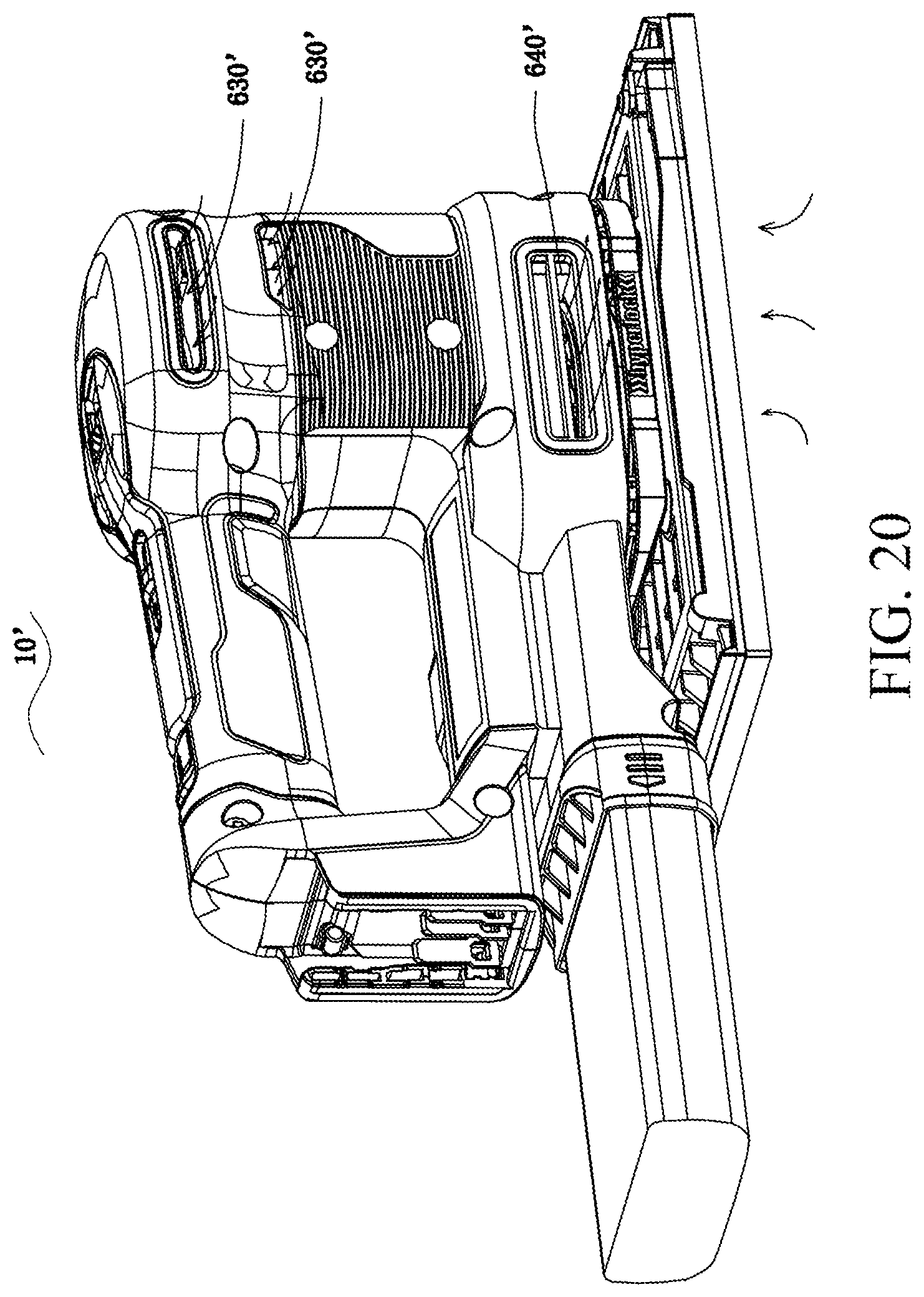
D00013

D00014
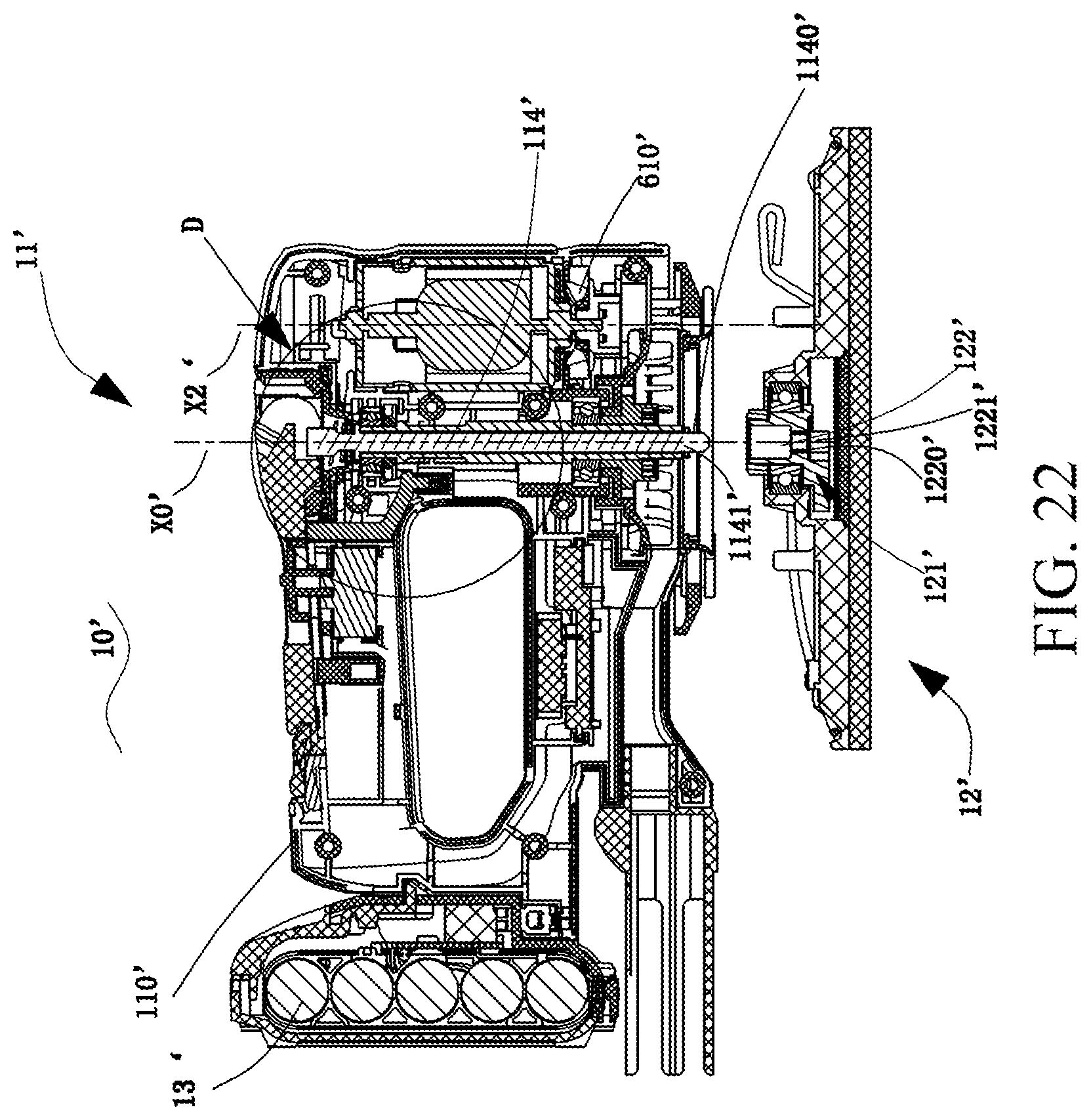
D00015
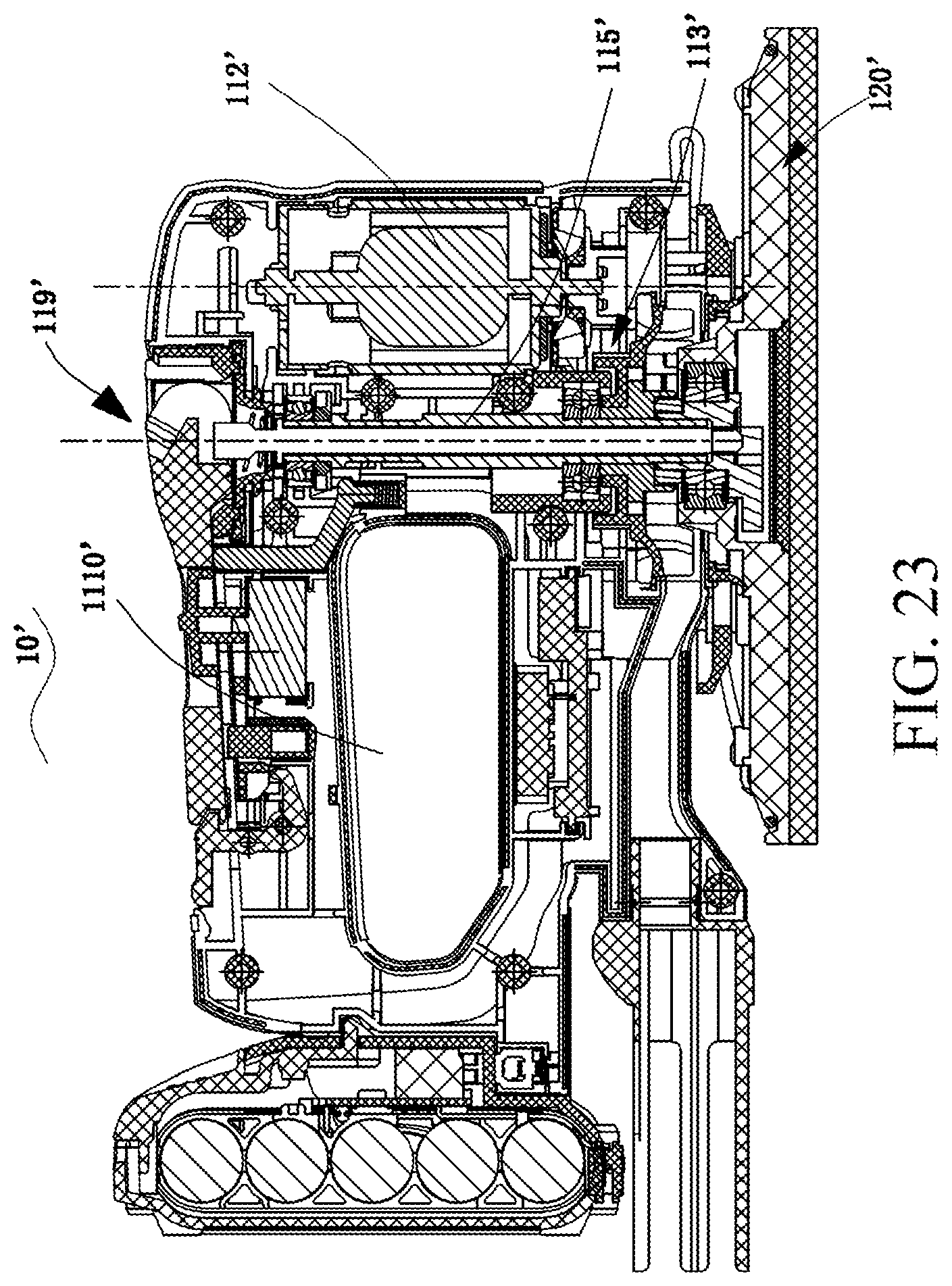
D00016
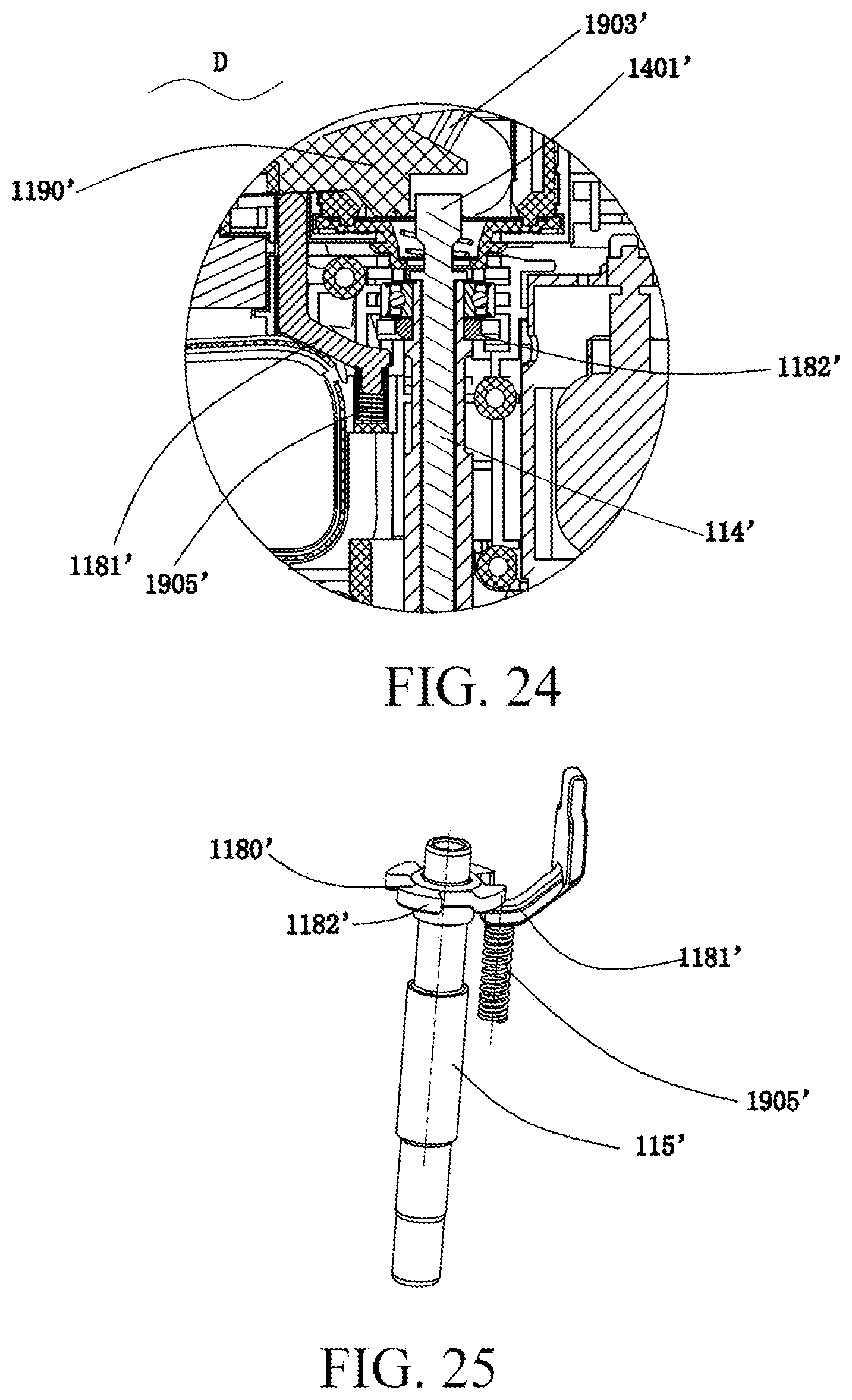
D00017
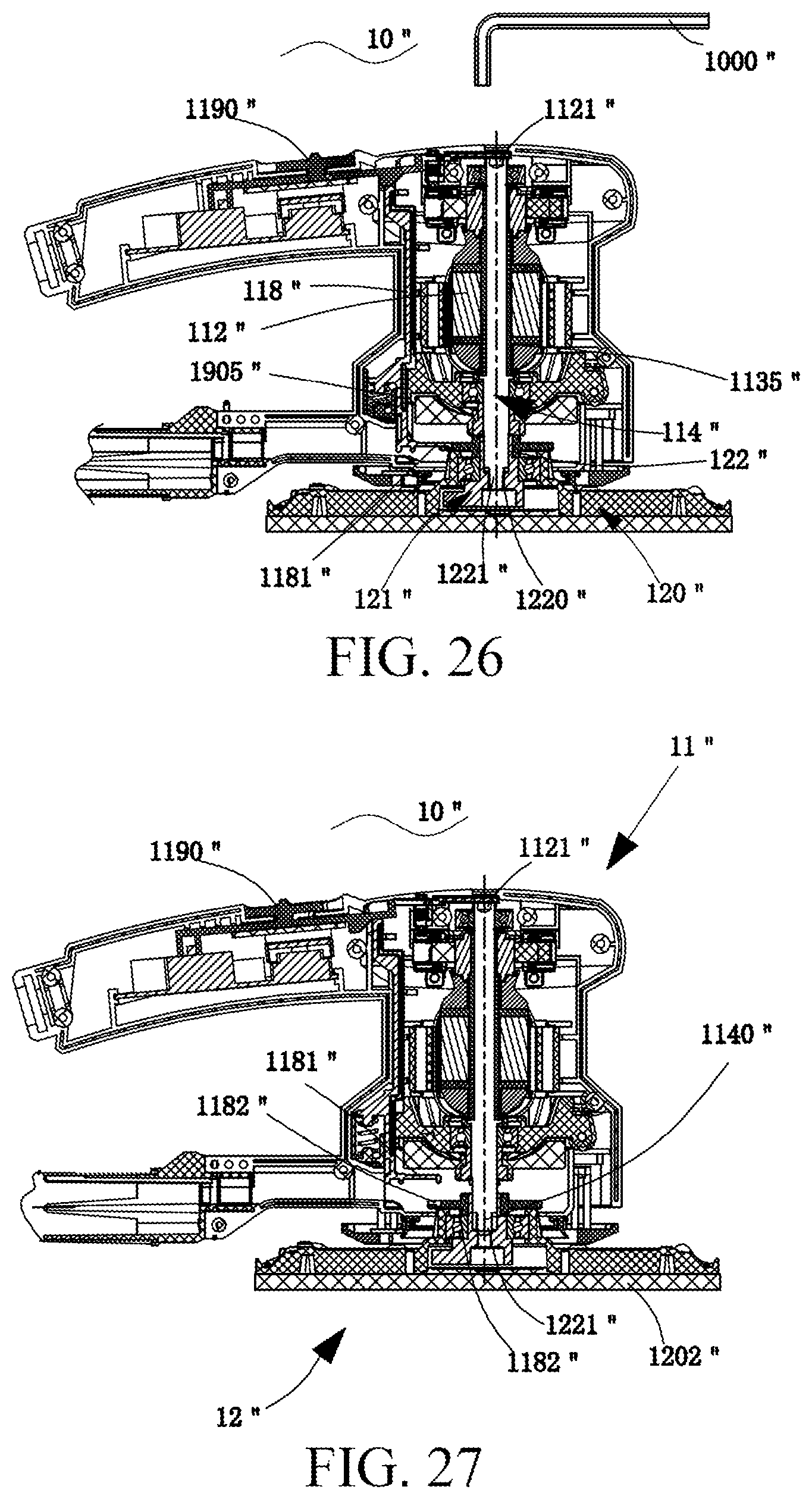
D00018
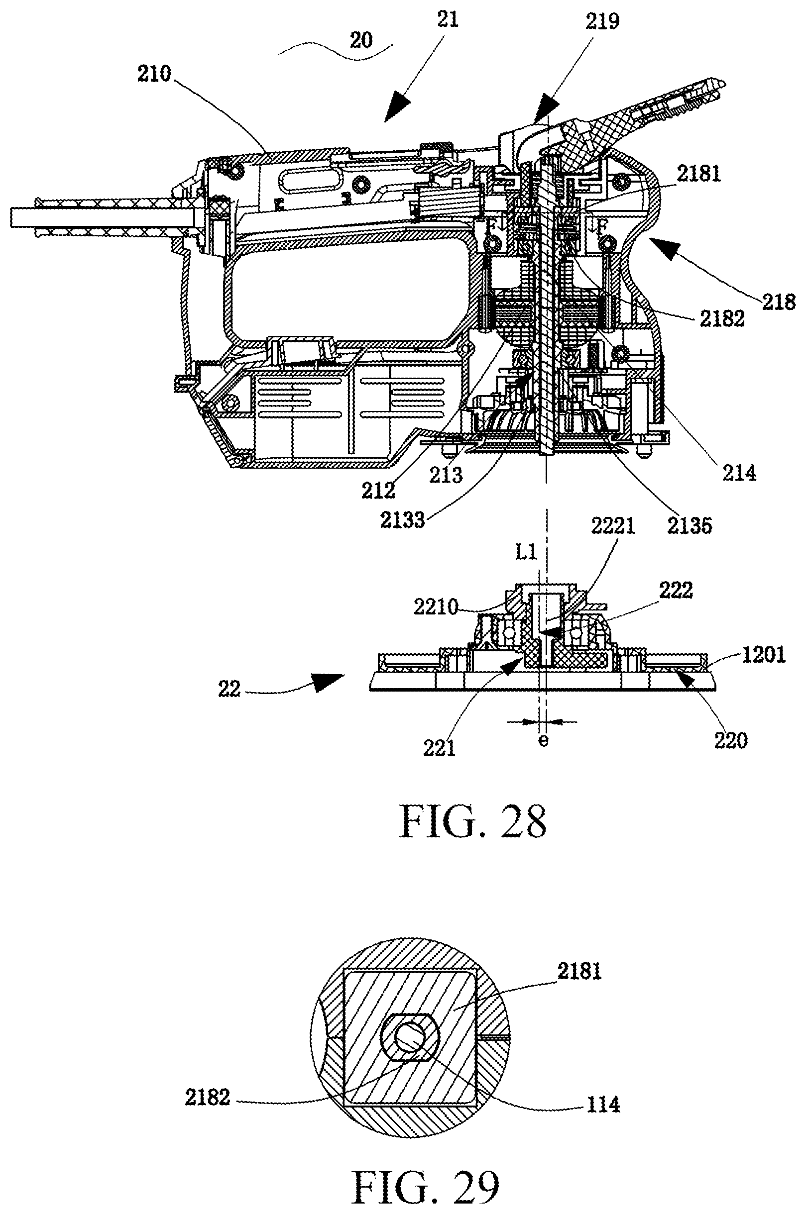
D00019
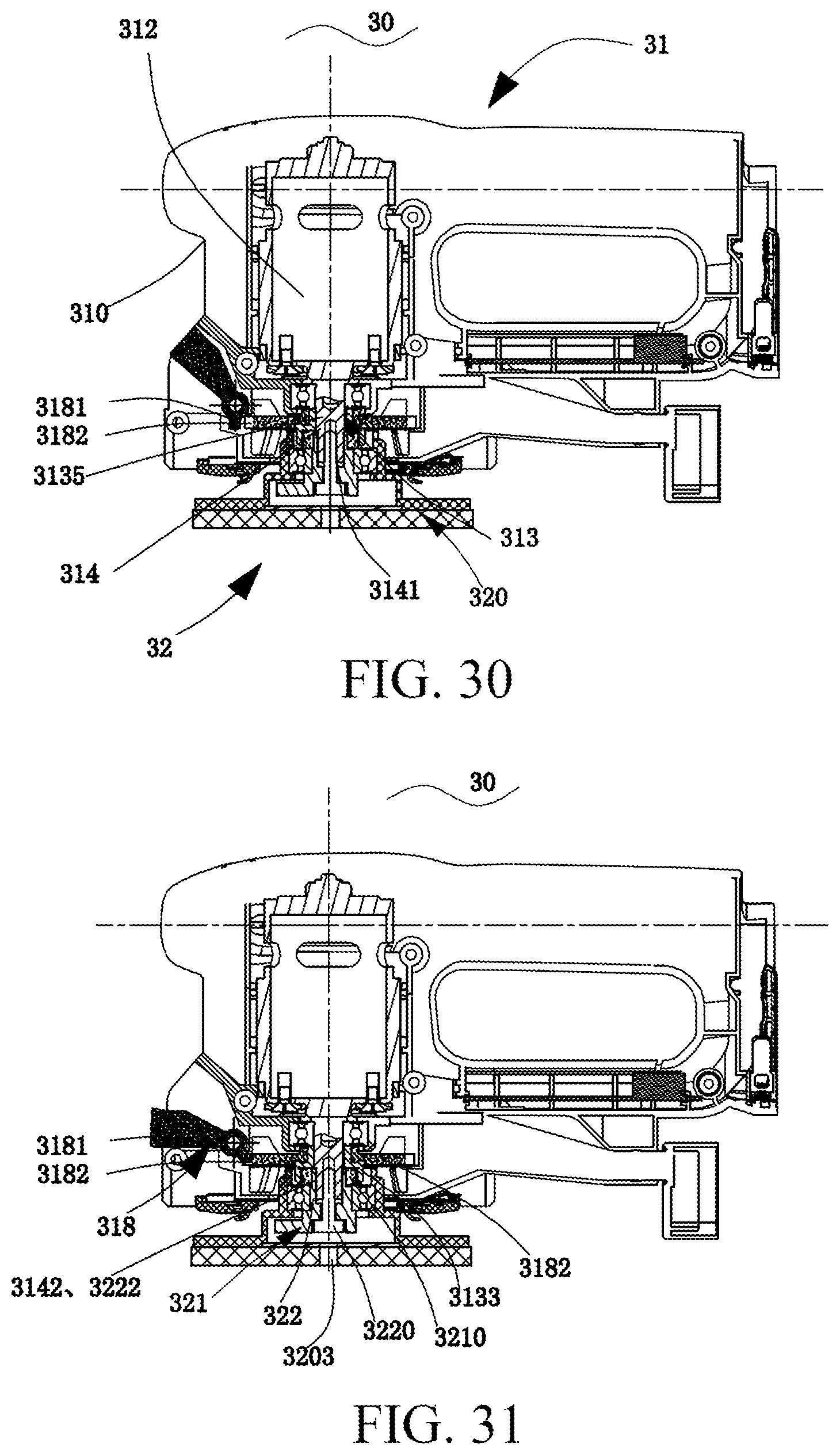
D00020
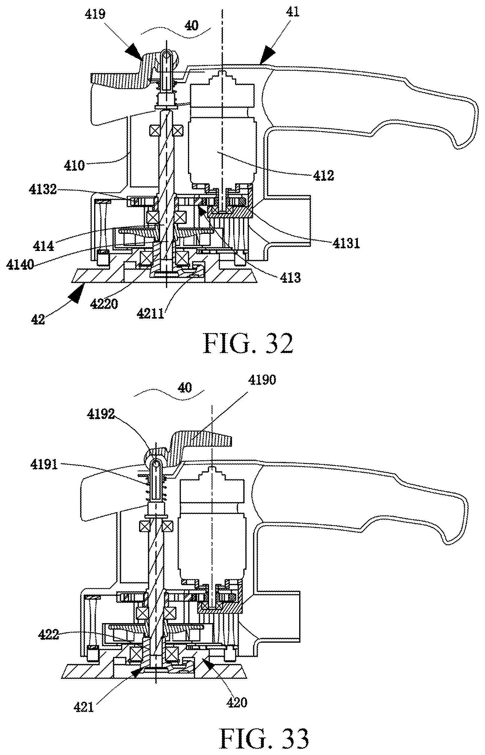
XML
uspto.report is an independent third-party trademark research tool that is not affiliated, endorsed, or sponsored by the United States Patent and Trademark Office (USPTO) or any other governmental organization. The information provided by uspto.report is based on publicly available data at the time of writing and is intended for informational purposes only.
While we strive to provide accurate and up-to-date information, we do not guarantee the accuracy, completeness, reliability, or suitability of the information displayed on this site. The use of this site is at your own risk. Any reliance you place on such information is therefore strictly at your own risk.
All official trademark data, including owner information, should be verified by visiting the official USPTO website at www.uspto.gov. This site is not intended to replace professional legal advice and should not be used as a substitute for consulting with a legal professional who is knowledgeable about trademark law.