Weighted Glute Bridge Apparatus
Hall; Richard Andrew ; et al.
U.S. patent application number 16/393391 was filed with the patent office on 2020-10-29 for weighted glute bridge apparatus. This patent application is currently assigned to Arsenal Strength LLC. The applicant listed for this patent is Arsenal Strength LLC. Invention is credited to Richard Andrew Hall, Bradley J. Holt.
| Application Number | 20200338391 16/393391 |
| Document ID | / |
| Family ID | 1000004049266 |
| Filed Date | 2020-10-29 |


View All Diagrams
| United States Patent Application | 20200338391 |
| Kind Code | A1 |
| Hall; Richard Andrew ; et al. | October 29, 2020 |
WEIGHTED GLUTE BRIDGE APPARATUS
Abstract
An apparatus for use in performing a weighted glute bridge exercise. A back support contacts a user's back and a foot support contacts at least one of the user's feet, with each supporting a portion of the user's weight. A rigid elongate arm is mounted adjacent the back support at a pivot point. A hip bar is connected to the elongate arm and is configured to contact a user's hip region throughout the exercise. When the user moves from a hip flexed position to a hip extended position, the elongate arm moves from a first pivotal position to a second pivotal position. A resistance loading area connected to the elongate arm applies a resistance force directly onto the user's hip region that opposes the motion. Reversing the motion moves the elongate arm from the second pivotal position back to the first pivotal position and completes the repetition.
| Inventors: | Hall; Richard Andrew; (Knoxville, TN) ; Holt; Bradley J.; (Knoxville, TN) | ||||||||||
| Applicant: |
|
||||||||||
|---|---|---|---|---|---|---|---|---|---|---|---|
| Assignee: | Arsenal Strength LLC Knoxville TN |
||||||||||
| Family ID: | 1000004049266 | ||||||||||
| Appl. No.: | 16/393391 | ||||||||||
| Filed: | April 24, 2019 |
| Current U.S. Class: | 1/1 |
| Current CPC Class: | A63B 21/00058 20130101; A63B 2225/09 20130101; A63B 21/4027 20151001; A63B 23/0405 20130101; A63B 21/4023 20151001 |
| International Class: | A63B 23/04 20060101 A63B023/04; A63B 21/00 20060101 A63B021/00 |
Claims
1. An apparatus for use in performing a weighted glute bridge exercise where a user alternates between a hip flexed position and a hip extended position, the apparatus comprising: a back support configured to contact a user's back and to support a portion of the user's weight; a foot support configured to contact at least one of the user's feet and to support a portion of the user's weight when the user's back is supported by the back support; a rigid elongate arm pivotally mounted adjacent a left side or a right side of the back support at a pivot point; a hip bar connected to the elongate arm at a hip bar connection and configured to contact the user's hip region throughout the exercise such that (i) when the user moves from the hip flexed position to the hip extended position, the elongate arm pivots about the pivot point from a first pivotal position to a second pivotal position in a first direction and (ii) when the user moves from the hip extended position to the hip flexed position, the elongate arm pivots about the pivot point from the second pivotal position to the first pivotal position in a second direction; and a resistance loading area for applying a resistance force to the elongate arm that resists pivotal movement of the elongate arm in the first direction, wherein the resistance loading area is disposed on the elongate arm in line with and vertically above the user's hip region such that the resistance force is applied substantially directly downwards at the user's hip region throughout the entire weighted glute bridge exercise.
2. The exercise apparatus of claim 1 wherein the rigid elongate arm comprises a rigid elongate arm pivotally mounted adjacent both sides of the back support and the hip bar is connected between the elongate arms.
3. The exercise apparatus of claim 2 further wherein each of the elongate arms has a first portion located on one side of the pivot point and a second portion located on an opposite side of the pivot point that is closer to the foot support than the first portion of the elongate arm, wherein the hip bar is connected between the second portions of the elongate arms and is configured to be selectively disconnected from at least one of the elongate arms.
4. The exercise apparatus of claim 3 wherein a rigid connection member connects the first portions of the elongate arms together such that the elongate arms pivot simultaneously with one another during the exercise.
5. The exercise apparatus of claim 3 wherein a hinged side of the hip bar is hinge mounted to one of the elongate arms such that the hip bar may swing between an open position and a closed position and wherein, when the hip bar is in the closed position, a locking side of the hip bar is configured to be removably connected to the other elongate arm via a lock that moves between an unlocked position, where the hip bar is configured to be pivoted about the hinge to the open position, and a locked position, where the hip bar is prevented from being pivoted about the hinge to the open position.
6. The exercise apparatus of claim 5 further comprising: a first tube disposed on the elongate arm the is located proximate the locking side of the hip bar; a second tube disposed on the back support that aligns with the first tube when the hip bar is in the closed position; and a sliding bolt that is configured to slide through the first and second tubes, wherein, when the lock is in the locked position, a portion of the sliding bolt is located in each of the first and second tubes, and wherein, when the lock is in the unlocked position, the sliding bolt is located in only one of the first and second tubes.
7. The exercise apparatus of claim 1 wherein the resistance loading area is an elongate post extending laterally outwards from the elongate arm that is configured to receive weight plates.
8. The exercise apparatus of claim 7 further comprising: rigid elongate arms are pivotally mounted adjacent both sides of the back support; a resistance loading area for applying a separate resistance force to each the elongate arm, wherein each resistance loading area is an elongate post extending laterally outwards from the elongate arm that is configured to receive weight plates, wherein each of the elongate arms has a first portion located on one side of the pivot point and a second portion located on an opposite side of the pivot point that is closer to the foot support than the first portion of the elongate arm, wherein the hip bar is connected between the second portions of the elongate arms and wherein elongate posts are concentrically aligned with the hip bar.
9. The exercise apparatus of claim 1 wherein the back support and the foot support remain fixed in place throughout the exercise.
10. The exercise apparatus of claim 1 wherein the foot support includes a first end and a hinged second end such that the first end of the foot support is configured to be raised and lowered about the hinged second end and fixed in at least two positions.
11. The exercise apparatus of claim 1 further comprising a pivot-limiting leg having a first end mounted to the elongate arm and a second end that is configured to contact a bearing surface once the elongate arm has pivoted sufficiently far enough about the pivot point in the second direction and, through that contact, to automatically prevent further pivot of the elongate arm about the pivot point in the second direction.
12. The exercise apparatus of claim 1 further comprising a catch that (i) when engaged, statically holds the elongate arm in a pivotal position that is between the first pivotal position and the second pivotal position and (ii) when disengaged, allows the elongate arm to freely pivot between the first pivotal position and the second pivotal position.
13. The exercise apparatus of claim 12 wherein the catch comprises: an arm that is pivotally mounted at one end between the back support and the foot support and that pivots about the one end between an engaged position and a disengaged position; a cradle formed at an opposite end of the arm, wherein the catch is engaged by moving the arm to the engaged position and placing the elongate arm into the cradle such that the elongate arm is statically held between the first pivotal position and the second pivotal position, and wherein the catch is disengaged by pivoting the elongate arm in the first direction to remove the elongate arm from the cradle and moving the arm to the disengaged position.
14. The exercise apparatus of claim 1 further comprising: rigid elongate arms that are pivotally mounted adjacent both sides of the back support; a catch located on each side of the back support adjacent an elongate arm that (i) when engaged, statically holds the elongate arm in a pivotal position that is between the first pivotal position and the second pivotal position and (ii) when disengaged, allows the elongate arm to freely pivot between the first pivotal position and the second pivotal position; and a linkage connecting the two catches together, such that engaging or disengaging one catch automatically engages or disengages the opposite catch, respectively.
15. An apparatus for use in performing a weighted glute bridge exercise where a user alternates between a hip flexed position and a hip extended position, the apparatus comprising: a back support having left and right sides, a front and a back and configured to be contacted by the user's back and to support a portion of the user's weight; a foot support configured to be contacted by at least one of the user's feet and to support a portion of the user's weight when the user's back is supported by the back support; a pivoting enclosure surrounding the left and right sides and the front of the back support, the pivoting enclosure formed by: elongate arms that are pivotally mounted adjacent the left and right sides of the back support; a hip bar connected between the elongate arms separating the back support and foot support; and a resistance loading area for applying a resistance force to the pivoting enclosure that resists pivotal movement of the pivoting enclosure in at least one direction, wherein the hip bar is aligned with the hip region of the user when the user's back is supported by the back support and the user's at least one foot is supported by the foot support, wherein the pivoting enclosure pivots in a first pivotal direction and the hip bar moves away from the foot support when the hip bar is in contact with the user's hip region and the user moves to the hip extended position. wherein the pivoting enclosure pivots in a second pivotal direction and the hip bar moves towards the foot support when the hip bar is in contact with the user's hip region and the user moves to the hip flexed position.
16. The apparatus of claim 15 wherein the resistance loading area includes a post extending laterally outwards from at least one of said elongate arms that is configured to receive weight plates.
17. The apparatus of claim 16 wherein a post that is configured to receive weight plates extends laterally outwards from each of said elongate arms and wherein the posts and the hip bar are collinear with each other.
18. The apparatus of claim 15 wherein one end of the hip bar is configured to selectively disconnect and swing away from one of the elongate arms to provide an opening for the user to enter the pivoting enclosure.
19. The apparatus of claim 15 wherein the elongate arms include a first portion that extend rearward behind the back of the back support and a second portion that extends forwards in front of the back support, and wherein a rigid connecting member is located behind the back of the back support and rigidly connects the elongate arms together such that the elongate arms pivot simultaneously with one another.
20. A method for performing a weighted glute bridge exercise comprising the steps of: A. providing a glute bridge apparatus comprising: a. a back support having left and right sides, a front and a back; b. a foot support; c. a pivoting enclosure surrounding the left and right sides and the front of the back support, the pivoting enclosure formed by: i. elongate arms that are pivotally mounted adjacent the left and right sides of the back support; ii. a hip bar connected between the elongate arms separating the back support and foot support that is configured to be contacted by a user's hip region and to pivot the pivoting enclosure in a first pivotal direction when the user's hips are moved in a first direction and to pivot the pivoting enclosure in a second pivotal direction when the user's hips are moved in a second direction; and d. a resistance loading area for applying a resistance force that resists pivotal movement of the pivoting enclosure in at least one pivotal direction, B. placing the user into the glute bridge apparatus such that the user's back contacts the back support and a portion of the user's weight is supported by the back support, at least one of the user's feet contacts the foot support and a portion of the user's weight is supported by the foot support, and the hip bar is in contact with the user's hip region; C. with the hip bar contacting the user's hip region, the user moving to the hip extended position such that the pivoting enclosure pivots in the first pivotal direction and the hip bar moves away from the foot support; and D. with the hip bar contacting the user's hip region, the user moving to the hip flexed position such that the pivoting enclosure pivots in the second pivotal direction and the hip bar moves towards the foot support.
Description
FIELD
[0001] The present invention relates generally to a strength training apparatus. More particularly, the present invention relates to a strength training apparatus for performing a hip thrust exercise for training the gluteus ("glute") muscles.
BACKGROUND
[0002] A common exercise routine used by athletes to train and specifically target their glute muscles is known as the "glute bridge" exercise. During the typical glute bridge exercise, the athlete places her back and at least one of her feet on a supporting surface to support her weight. Her back and foot remain in contact with these support surfaces throughout the entire exercise. In the concentric phase of the exercise, the athlete pushes her hips forward while contracting her glute muscles (the "up" or "hip extended" position). In this up position, the athlete's upper body and upper leg (i.e., femur) are aligned and form a substantially straight line or an angle of approximately 180.degree. is formed at the athlete's hips and extends from the athlete's shoulders to her knees. In the eccentric phase of the exercise, the athlete flexes her hips rearwards and relaxes her glute muscles (the "down" or "hip flexed" position). In this down position, the athlete's upper body and upper leg are approximately orthogonal to one another such that an approximate angle of 90.degree. is formed at the athlete's hips by her torso and femur.
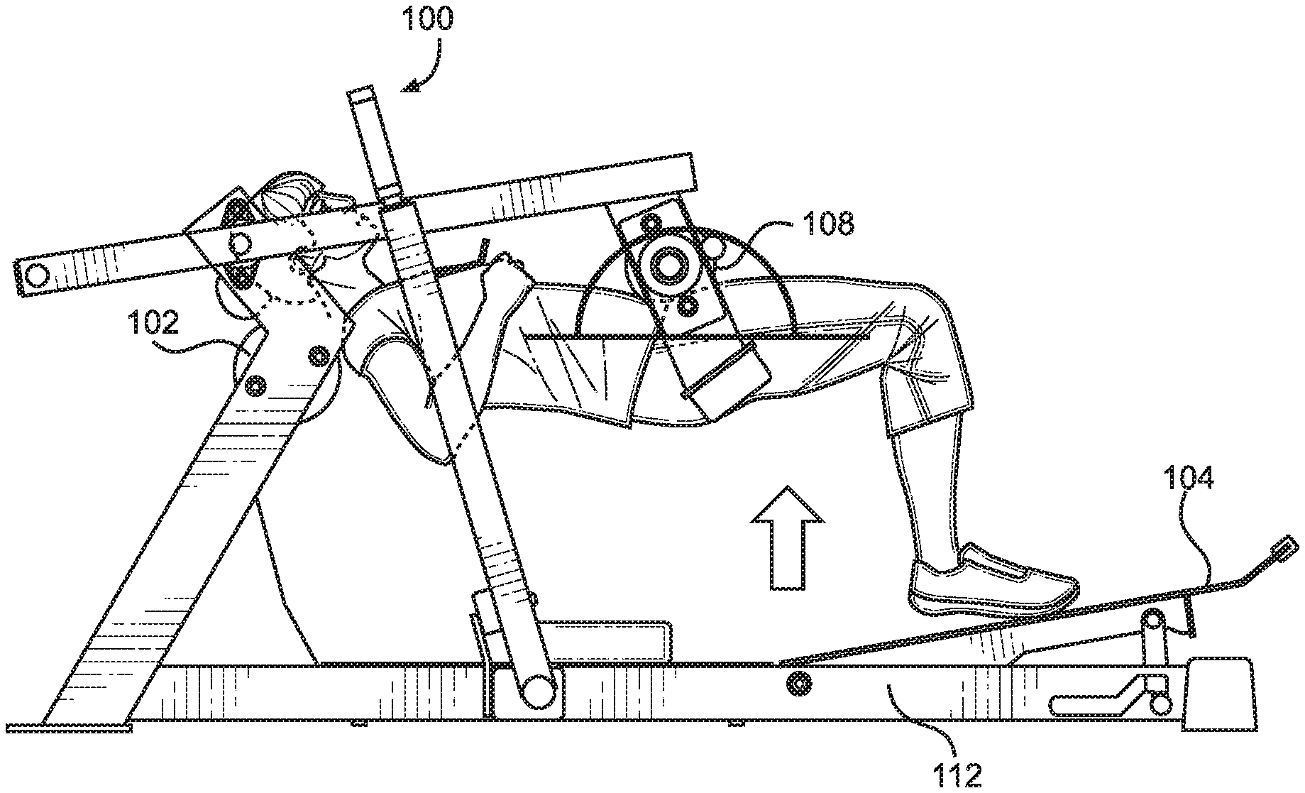
[0003] In its simplest form, the glute bridge may be performed on the floor or other ground surface without any equipment. In that case, the athlete's shoulders and feet are supported by the ground surface. One disadvantage to performing the glute bridge exercise with back and feet supported by surfaces on the same plane (i.e., both supported by the ground) is that it provides limited range of motion, which limits the effectiveness of the exercise. One way to improve the effectiveness of the exercise routine through increasing the range of motion is for the athlete to place her back on a support surface that is on a different plane (typically a higher plane) from the surface supporting her feet, as shown in FIGS. 1 and 2. This variety of the glute bridge, where the back is elevated with respect to the feet, is often called a "hip thrust." In FIG. 1, the athlete's back is supported by a bench and his feet are supported by the floor. He is in the down or hip flexed position and an angle of approximately 90.degree. is formed at his hip by his torso and femur. An angle of approximately 90.degree. is also formed at his knee by his femur and tibia (shin bone). In FIG. 2, the athlete's back is still supported by the bench and his feet are still supported by the floor. He is in the up or hip extended position and an angle of approximately 180.degree. is formed at his hip by his torso and femur. However, an angle of approximately 90.degree. is still formed at his knee by his femur and tibia. This approximate 90.degree. angle formed at the knee remains constant throughout the exercise.
[0004] The difficulty of the glute bridge exercise may be increased by applying resistance to the movement of the athlete's hips. Often, this is accomplished by placing a barbell across the athlete's hips, which the athlete must then raise during the concentric phase of the exercise, as shown in FIGS. 1 and 2. However, a disadvantage of performing a weighted glute bridge using a free barbell is that balancing the weight can be difficult, particularly for novice athletes. Additionally, because the motion of the barbell is unrestricted, it may travel along different motion paths from one repetition to the next, which can impact its effectiveness and the consistency of results.
[0005] Accordingly, what is needed is a method and apparatus that offers the advantages of performing an elevated glute bridge exercise (hip thrust) that addresses the disadvantages discussed above.
Notes on Construction
[0006] The use of the terms "a", "an", "the" and similar terms in the context of describing embodiments of the invention are to be construed to cover both the singular and the plural, unless otherwise indicated herein or clearly contradicted by context. The terms "comprising", "having", "including" and "containing" are to be construed as open-ended terms (i.e., meaning "including, but not limited to,") unless otherwise noted. The terms "substantially", "generally" and other words of degree are relative modifiers intended to indicate permissible variation from the characteristic so modified. The use of such terms in describing a physical or functional characteristic of the invention is not intended to limit such characteristic to the absolute value which the term modifies, but rather to provide an approximation of the value of such physical or functional characteristic.
[0007] Terms concerning attachments, coupling and the like, such as "attached", "connected" and "interconnected", refer to a relationship wherein structures are secured or attached to one another either directly or indirectly through intervening structures, as well as both moveable and rigid attachments or relationships, unless otherwise specified herein or clearly indicated as having a different relationship by context. The term "operatively connected" is such an attachment, coupling or connection that allows the pertinent structures to operate as intended by virtue of that relationship.
[0008] The use of any and all examples or exemplary language (e.g., "such as" and "preferably") herein is intended merely to better illuminate the invention and the preferred embodiments thereof, and not to place a limitation on the scope of the invention. Nothing in the specification should be construed as indicating any element as essential to the practice of the invention unless so stated with specificity.
[0009] The term "femur angle" is relative to a linear approximation of the user's spine. The "hip region" is located generally on the front of the user's body and extends generally from the top of the hipbone downwards to approximately midpoint of the femur. The term "hip flexed position" means that the user's hips are generally flexed rearward and (i) the user has a femur angle of approximately 90.degree., (ii) the user's back is supported by a back support, and (iii) the user's foot of the leg whose femur is angled at approximately 90.degree. is supported by a foot support. The term "hip extended position" means that the user's hips are generally extended forward and (i) the user has a femur angle of approximately 180.degree., (ii) the user's back is supported by a back support, and (iii) the user's foot of the leg whose femur is angled at approximately 180.degree. is supported by a foot support.
SUMMARY
[0010] The above and other needs are met by an apparatus for use in performing a weighted glute bridge exercise where a user alternates between a hip flexed position and a hip extended position. The apparatus includes a back support that contacts a user's back and supports a portion of the user's weight and a foot support that contacts at least one of the user's feet and also supports a portion of the user's weight when the user's back is supported by the back support. The back support and the foot support remain fixed in place throughout the exercise. However, in certain preferred embodiments, the foot support includes a first end and a hinged second end such that the first end of the foot support may be raised and lowered about the hinged second end and fixed in at least two positions.
[0011] A rigid elongate arm is pivotally mounted adjacent a left side or a right side of the back support at a pivot point. A hip bar is connected to the elongate arm at a hip bar connection and is configured to contact the user's hip region throughout the exercise. When the user moves from the hip flexed position to the hip extended position, the elongate arm moves from a first pivotal position to a second pivotal position (in a first direction). When the user moves from the hip extended position to the hip flexed position, the elongate arm moves from the second pivotal position back to the first pivotal position (in a second direction). A resistance loading area may be used to optionally apply a resistance force to the elongate arm that resists pivotal movement of the elongate arm in the first direction to increase the difficulty of the exercise. The resistance loading area is located on the elongate arm near the hip bar connection such that the resistance force is applied substantially directly onto the user's hip region in order to closely replicate conventional weight hip thrust exercises.
[0012] In certain preferred embodiments, rigid elongate arms are pivotally mounted adjacent both sides of the back support and the hip bar is connected between the elongate arms. Each of the elongate arms has a first portion located on one side of the pivot point and a second portion located on an opposite side of the pivot point that is closer to the foot support than the first portion of the elongate arm. The hip bar is preferably connected between the second portions of the elongate arms and may be selectively disconnected from at least one of the elongate arms. A rigid connection member connects the first portions of the elongate arms together such that the elongate arms pivot simultaneously with one another during the exercise.
[0013] According to certain embodiments, a hinged side of the hip bar is hinge mounted to one of the elongate arms such that the hip bar may swing between an open position and a closed position. When the hip bar is in the closed position, a locking side of the hip bar (located opposite the hinged side) may be removably connected to the other elongate arm via a lock. The lock moves between an unlocked position, where the hip bar may be pivoted about the hinge to the open position, and a locked position, where the hip bar is prevented from being pivoted about the hinge to the open position. The lock may include a first tube located on the elongate arm that is located proximate the locking side of the hip bar. In that case, a corresponding second tube is also located on the back support and it aligns with the first tube when the hip bar is in the closed position. A sliding bolt is configured to slide through the first and second tubes. When the lock is in the locked position, a portion of the sliding bolt is located in each of the first and second tubes. When the lock is in the unlocked position, the sliding bolt is located in only one of the first and second tubes.
[0014] In certain preferred embodiments, the resistance loading area is an elongate post extending laterally outwards from the elongate arm that is configured to receive weight plates. In certain embodiments, rigid elongate arms are pivotally mounted adjacent both sides of the back support and resistance loading areas are provided on each elongate arm. The resistance loading areas preferably allow a separate resistance force to be applied to each of the elongate arms. In preferred embodiments, each resistance loading area is an elongate post extending laterally outwards from the elongate arm that is configured to receive weight plates. The elongate arms have a first portion located on one side of the pivot point and a second portion located on an opposite side of the pivot point that is closer to the foot support than the first portion of the elongate arm. Preferably, the hip bar is connected between the second portions of the elongate arms and the elongate posts are concentrically aligned with the hip bar to closely replicate the appearance and performance characteristics of a conventional weight hip thrust exercises with a barbell.
[0015] Certain embodiments of the apparatus are provided with a pivot-limiting leg. A first end of the pivot-limiting leg is mounted to the elongate arm and a second end is configured to contact a bearing surface once the elongate arm has pivoted sufficiently far enough about the pivot point in the second direction. Through that contact, the pivot-limiting leg automatically prevents further pivoting of the elongate arm about the pivot point in the second direction.
[0016] Certain embodiments of the apparatus includes a catch that (i) when engaged, statically holds the elongate arm in a pivotal position that is between the first pivotal position and the second pivotal position and (ii) when disengaged, allows the elongate arm to freely pivot between the first pivotal position and the second pivotal position. Preferably, the catch includes an arm that is pivotally mounted at one end between the back support and the foot support and that pivots about the one end between an engaged position and a disengaged position. A cradle is formed near an end of the arm that is opposite the pivot point. The catch is engaged by pivoting the arm to the engaged position and placing the elongate arm into the cradle such that the elongate arm is statically held between the first pivotal position and the second pivotal position. The catch is disengaged by pivoting the elongate arm in the first direction to remove the elongate arm from the cradle and moving the arm to the disengaged position. In certain embodiments, rigid elongate arms are pivotally mounted adjacent both sides of the back support and a catch is located on each side of the back support to support an elongate arm, as described above. Preferably, a linkage connects the two catches together, such that engaging or disengaging one catch will also automatically engage or disengage the opposite catch, respectively.
BRIEF DESCRIPTION OF THE DRAWINGS
[0017] Further advantages of the invention are apparent by reference to the detailed description when considered in conjunction with the figures, which are not to scale so as to more clearly show the details, wherein like reference numerals represent like elements throughout the several views, and wherein:
[0018] FIGS. 1 and 2 depict an athlete performing a conventional glute bridge exercise using a bench and a barbell free weight;
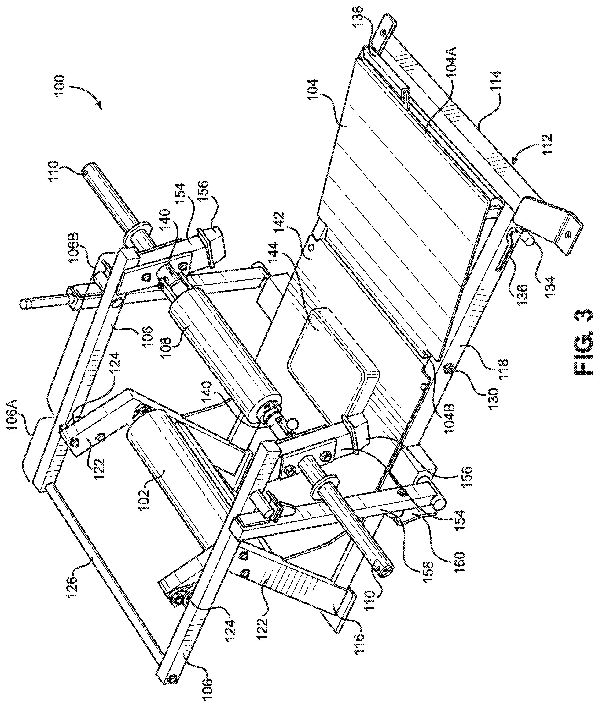
[0019] FIG. 3 is a front perspective view depicting an exercise apparatus for performing a weighted glute bridge according to an embodiment of the present invention;
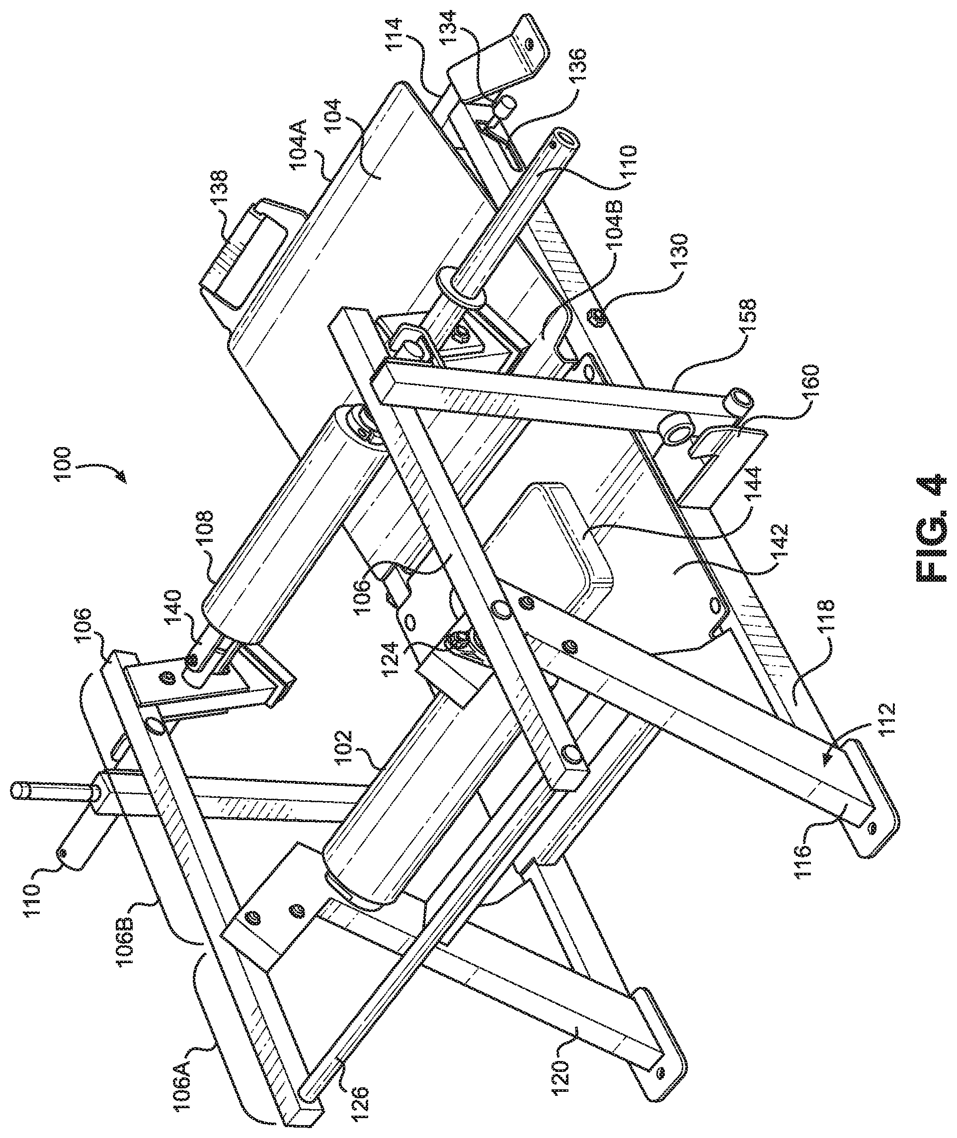
[0020] FIG. 4 is a rear perspective view of the apparatus of FIG. 3;
[0021] FIG. 5 is a left-side elevation view of the apparatus of FIG. 3 in the "up" position;
[0022] FIG. 6 is a left-side elevation view of the apparatus of FIG. 3 in the "down" position;
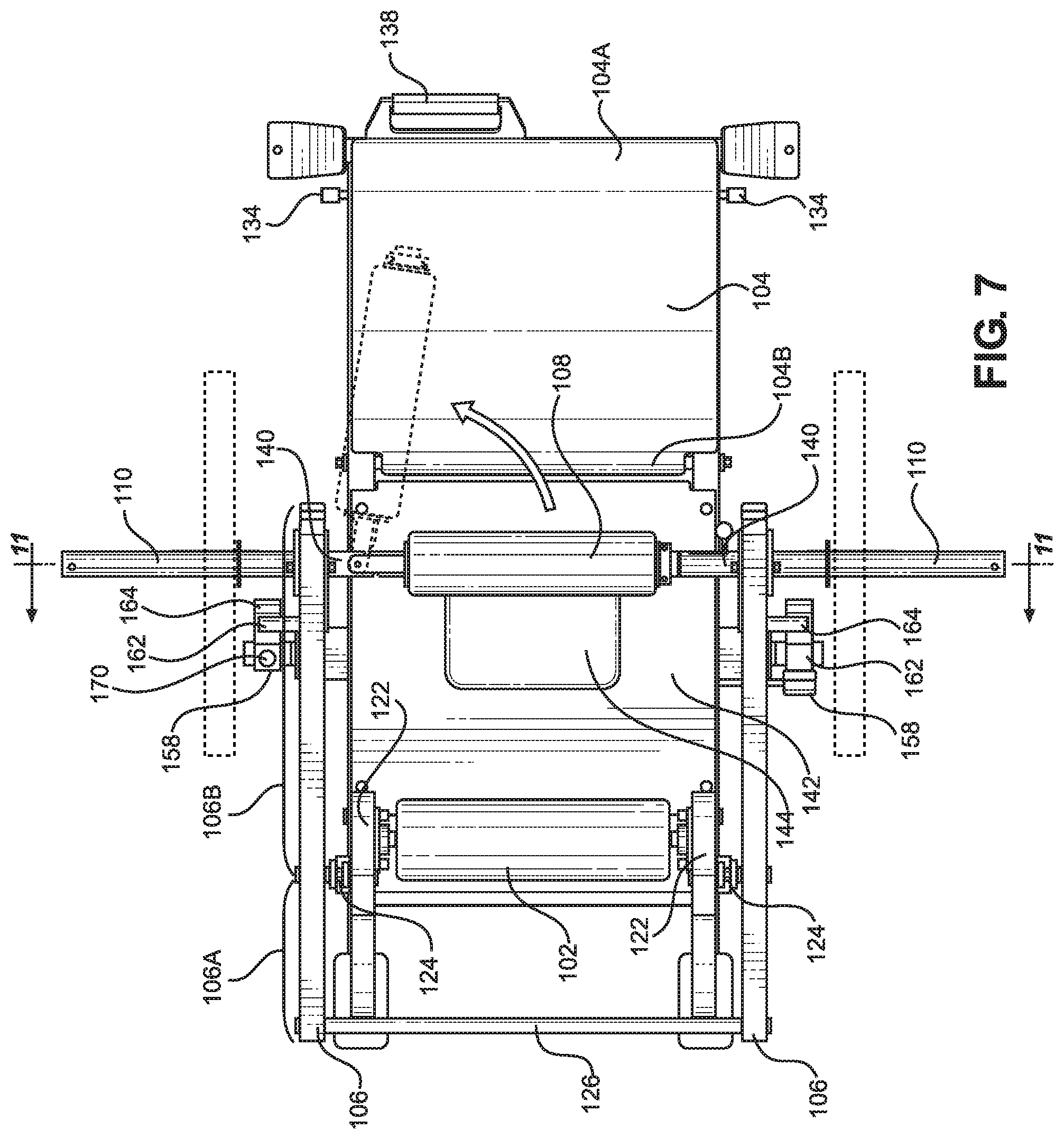
[0023] FIG. 7 is a top plan view of the apparatus of FIG. 3 illustrating a swing away hip bar;
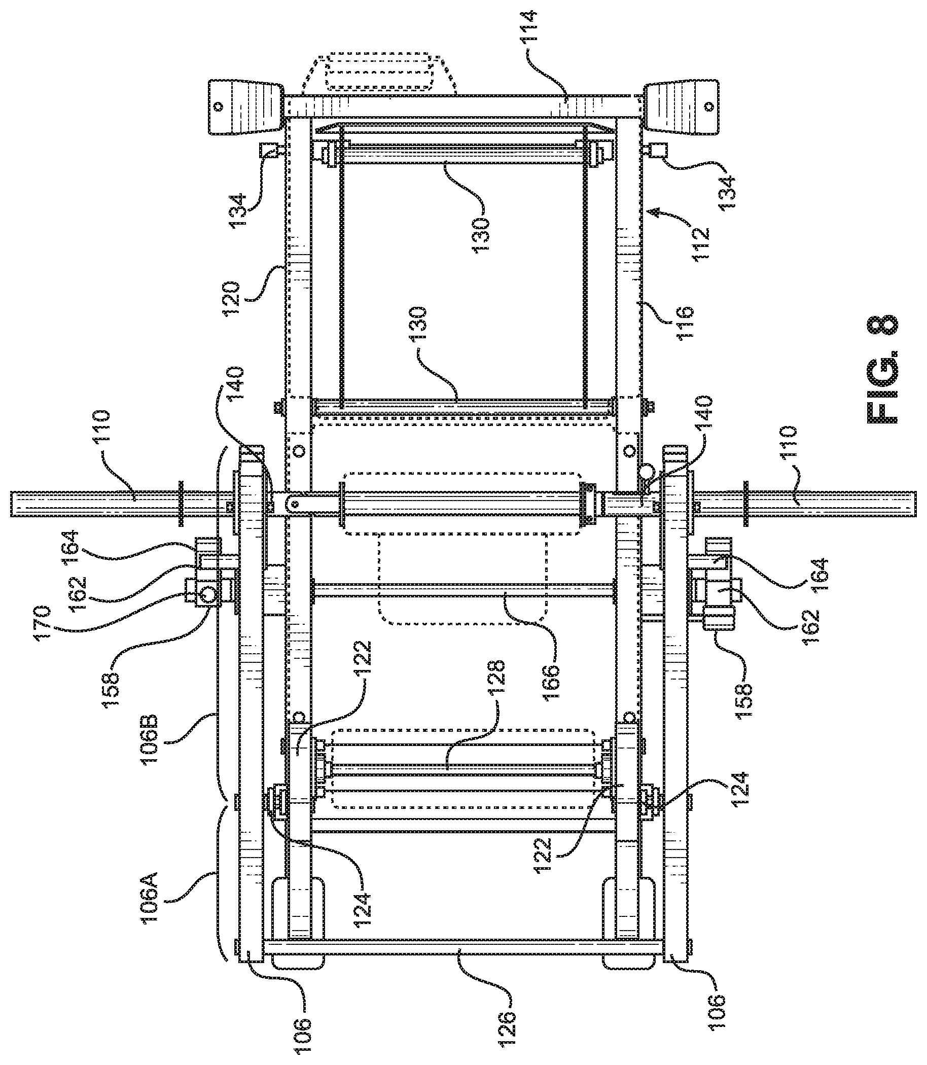
[0024] FIG. 8 is a top plan view of the apparatus of FIG. 3 with a back support, foot support, middle support, hip bar removed to illustrate supporting structures for these components;
[0025] FIG. 9 is a bottom plan view of the apparatus of FIG. 3;
[0026] FIG. 10 is a front elevation view of the apparatus of FIG. 3;
[0027] FIG. 11 is a sectional view taken along line "11-11" in FIG. 7 illustrating an at least partially hollow bar extending along the width of the apparatus;
[0028] FIG. 12 is a detail view of the portion of the apparatus marked "FIG. 12" in FIG. 10;
[0029] FIG. 13 is a detail view of the portion of the apparatus marked "FIG. 13" in FIG. 10;
[0030] and
[0031] FIGS. 14 and 15 depict an athlete performing a glute bridge exercise using the apparatus of FIG. 3 according to a method of the present invention.
DETAILED DESCRIPTION
[0032] Referring now to FIGS. 3-6, there is provided an apparatus 100 for use in performing a weighted glute bridge exercise according to an embodiment of the present invention. The apparatus 100 generally includes a back support 102 and a foot support 104, at least one rigid elongate arm 106 extending at least partially along the length of the apparatus, a hip bar 108 extending at least partially across the width of the apparatus, and at least one resistance loading area 110. To use the apparatus 100, a user first assumes the hip flexed positioned by placing his back against the back support 102, his feet on the foot support 104, and his hip region under the hip bar 108. Next, the user brings his hip region into contact with the hip bar 108 and, by pressing his hips upwards, moves from the hip flexed position to the hip extended position. During this motion, the elongate arm 106 pivots upwards away from the foot support 104 in a first direction A from a first pivotal position to a second pivotal position. The user then moves from the hip extended position to the hip flexed position by lowering his hips and allowing the hip bar 108 to be lowered towards the foot support 104. During this movement, the elongate arm 106 pivots in a second direction B from the second pivotal position to the first pivotal position, which completes the repetition.
[0033] In the illustrated embodiment, the apparatus 100 includes a supporting frame or base 112 that is placed onto a ground surface. The base has a front 114, rear 116, left side 118, and right side 120. Risers 122 extend generally vertically upwards from the left and right sides 118, 120 at the rear 116 of the base 112. The back support 102 is mounted between the two risers 122 at approximately 2/3 the height of the risers. The back support 102 is configured to contact a user's back and to support a portion of the user's weight. In this embodiment, the back support is formed by a rod (128, shown in FIG. 8) that is rigidly mounted between the risers 122 and that is covered by a padded outer covering.
[0034] The foot support 104 is a plate-like surface that preferably extends from just in front of the hip bar 108 to the front 114 of the base 112. Preferably, the foot support 104 includes a first end 104A and a hinged second end 104B that is closer to the back support 102 than the first end. Preferably, the first end 104A of the foot support 104 may be raised and lowered about the hinged second end 104B and fixed in at least two positions.
[0035] As shown best in FIGS. 5 and 9, a hinge 130 connects the second end 104B of the foot support 104 to the to the base 112 to allow the first end 104A to be raised and lowered about the second end. One end of a collapsible leg 132 is mounted near the first end 104A of the foot support 104 by another hinge 130. The opposite end of the collapsible leg 132 is mounted to rods 134 that extend through each of the left and right sides 118, 120 of the base 112. Ends of the rods 134 extend out of corresponding slots 136 that are formed in each of the left and right sides 118, 120 of the base 112 and guide the motion of the rod along the slot and their enlarged ends secure the rod in the slot. When the rod 134 is positioned at the end of the slot 136 nearest the first end 104A of the foot support 104, the foot support is held at an inclined angle. When the rod 134 is positioned at the end of the slot 136 nearest the second end 104B of the foot support 104, the foot support is held substantially horizontally. Preferably, in the inclined position, the foot support 104 is inclined approximately 5.degree.-20.degree. from the horizontal position. More preferably, in the inclined position, the foot support 104 is inclined approximately 10.degree. from the horizontal position. In other embodiments, the foot support 104 may be fixed at three or more positions, including a horizontal position and at least two different inclined positions. In still other embodiments, the angle of incline of the foot support 104 is infinitely adjustable.
[0036] Preferably, a handle 138 is provided on the foot support 104 to facilitate raising and lowering the foot support. The slot 136 and hinge 130 are preferably configured such that pulling upwards on the handle 138 to lift the foot support 104 automatically causes the rod 134 to slide along the slot and, once the handle is released, to automatically be seated at the end of the slot nearest the first end 104A of the foot support 104, such that the foot support is held at an inclined angle. To lower the foot support 104, the first end 104A is first raised and then the rod 134 is pushed rearward along the slot 136 towards the second end 104B of the foot support. Since both rods 134 are connected to the same hinge 130, which acts as a linkage, moving a rod on one side of the apparatus 100 (e.g., the right side) also simultaneously moves the rod on the opposite side of the apparatus (e.g., the left side). This allows the angle of incline of the foot support 104 to be adjusted from either the left or right side of the apparatus 100.
[0037] The foot support 104 is configured to contact at least one of the user's feet and to support a portion of the user's weight when the user's back is supported by the back support 102. As discussed above, the foot support 104 is preferably a plate-like surface. However, in other embodiments, the foot support 104 could be a ground, floor, or other surface. To mimic the elevated hip thrust discussed above, the back support 102 and foot support 104 are preferably located on two different vertical planes (i.e., the back support is vertically higher than the foot support). More preferably, the top of the back support 102 is raised to a vertical height above the foot support 104 by a distance that replicates the height difference between the top of a standard weightlifting bench and the ground surface that it rests on (approximately 18'' to approximately 24''). In some embodiments, either of the back support 102 and foot support 104 may be moved, pivoted, rotated. An example of a pivoting foot support 104 is described below. However, the back support 102 and foot support 10 preferably remain fixed in place throughout the exercise in order to provide a stable support surface for the user.
[0038] Referring again to FIGS. 3-6, the rigid elongate arms 106 are pivotally mounted adjacent a left side or a right side of the back support 102 at a pivot point 124 that is located on the outside surface of the risers 122. Due to their being pivotally mounted at one end, the motion of the elongate arms 106 is constrained to an up and down circular path about the pivot point 124. As a result, the motion path of each repetition of the glute raise remains consistent, which provides more consistent results than the convention glute raise discussed above. It is possible for the elongate arms 106 to each pivot about their respective pivot points 124 independently of one another. However, in preferred embodiments, the elongate arms 106 pivot simultaneously with one another during the exercise. To ensure that the elongate arms 106 pivot simultaneously with one another, a rigid connection member 126 connects the two elongate arms together. More particularly, each elongate arm 106 includes a first portion 106A that is located on one side of the pivot point 124 and a second portion 106B located on an opposite side of the pivot point that is closer to the foot support 104 than the first portion of the elongate arm. The rigid connection member 126 is connected between the first portions 106A of the elongate arms 106. Thus, the rigid connecting member 126 is spaced sufficiently far enough behind the back support 102 that it does not interfere with the user while they perform the exercise.
[0039] As shown in FIGS. 3 and 4, the hip bar 108 is connected between the second portions 106B of the elongate arms 106 via a hip bar connection 140. The hip bar 108 is located between the back support 102 and the foot support 104 and is positioned such that it contacts the user's hip region when the user's back is supported by the back support 102 and at least one of the user's feet is supported by the foot support 104. The user's hip region remains in contact with the hip bar 108 throughout the exercise. When the user moves from the hip flexed position to the hip extended position, the elongate arm 106 moves from a first pivotal position to a second pivotal position. When the user moves from the hip extended position to the hip flexed position, the elongate arm 106 moves from the second pivotal position to the first pivotal position. In some embodiments, a separate hip bar 108 extends from each of the hip bar connections 140 located on the left and right sides of the apparatus 100. In that case, each hip bar would contact one side (i.e., left or right) of the athlete's hip region during the exercise. However, more preferably, a single hip bar 108 extends across the width of the apparatus 100 and is connected at opposing ends between the hip bar connections 140. Thus, a pivoting enclosure that surrounds at least the left and right sides and the front of the back support 102 is formed by the elongate arms 106 and the hip bar 108. When the apparatus 100 is equipped with the rigid connection member 126, it also forms part of the pivoting enclosure and surrounds the back of the back support 102. The pivoting enclosure surrounds the user's upper body during the exercise and pivots, as a single unite about the pivot points 124.
[0040] As discussed above, to perform the exercise, the user first assumes the hip flexed position with his hip region located below the hip bar 108. To accomplish this, the user may first step into the pivoting enclosure between the back support 102 and hip bar 108 and then seat himself on a middle support 142, which may be provided with a padded seat 144. Once seated, the user then positions his back against the back support 102 and his feet onto the foot support 104, raises his hip region to the hip 108, and begins the exercise.
[0041] However, more preferably, at least one side of the hip bar 108 may be selectively disconnected from at least one of the elongate arms 106 in order to provide more convenient access to the pivoting enclosure. For example, in some embodiments, both sides of the hip bar 108 may be disconnected from the elongate arms 106 via a removable hip bar connection 140. In other embodiments, only one side of the hip bar 108 is disconnected. For example, as illustrated in FIG. 7, the hip bar 108 is provided with a hinged hip bar connection located on one side of the hip bar and a locking hip bar connection located on the opposite side of the hip bar. This hinged and locking hip bar may swing open on one side to provide an opening to allow the user more convenient access to the pivoting enclosure.
[0042] More detailed views of the hinged hip bar connection and the locking hip bar connection are provided in FIGS. 10-13. The hip bar 108 swings between an open and closed position. When the hip bar 108 is in the closed position, the locking side (FIG. 12) of the hip bar may be removably connected to the adjacent elongate arm 106 via a lock. The lock moves between an unlocked position, where the hip bar 108 may be pivoted about the hinged side (FIG. 13) to the open position, and a locked position, where the hip bar is prevented from being pivoted about the hinged side to the open position. In this particular embodiment, the lock is formed by a pair of tubes 146, including one tube in the hip bar 108 and another tube mounted to the elongate arm 106, whose open ends align when the hip bar is in the closed position and a sliding bolt 148 that slides through the tubes. In the illustrated embodiment, a handle 150 extends through a slot 152 formed in one of the tubes 146 and connects to the bolt 146. To engage the lock, the user aligns the open ends of the tubes 146, grasps the handle 150, and slides the bolt 148 to the right (as shown in FIG. 12) along the slot 152 until a portion of the bolt is located in each of the tubes. To disengage the lock, the user grasps the handle 150 and slides the bolt 148 to the left (as shown in FIG. 12) along the slot 152 until the bolt is located in only one of the tubes.
[0043] As discussed above, the difficulty of the glute bridge exercise may be increased by applying resistance to the movement of the athlete's hips. Traditionally, this is done by placing a weighted barbell across the athlete's hip region. Accordingly, in preferred embodiments, the apparatus 100 is provided with the resistance loading area 110, which may be used for applying a resistance force to the user's hip region. Referring again to FIGS. 3-6, the resistance loading area 110 is located on the elongate arm 106 near the hip bar connection 140 such that the resistance force is transmitted to the hip bar 108 and is applied substantially directly onto the user's hip region throughout the entire exercise. That resistance force resists pivotal movement of the elongate arm 106 as the user extends his hips forward. Applying the resistance force directly over the user's hip region (rather than at some distance spaced away from the hip region) causes the performance of the glute bridge exercise using the apparatus 100 to more closely resemble performing conventional glute bridge exercises with a weighted barbell placed across the user's hip region.
[0044] The resistance loading area 110 and the type of resistance applied may take many forms. For example, a resistance band could be connected between the elongate arm and the base 112 via hooks that are located on each structure. Alternatively, one end of a cable could be connected to the elongate arm 106 at the resistance loading area 110. The cable could then be routed to a weight stack using known methods to provide an easily adjustable resistance load. In the illustrated embodiment, the resistance loading area 110 is an elongate post that extends laterally outwards from the elongate arm 106 and that is configured to receive weight plates.
[0045] In order to more closely replicate the feel and performance of conventional weighted glute bridge exercises, the apparatus 100 preferably includes a pair of elongate posts 110 that extend laterally outwards in opposite directions from the elongate arms 106. These posts are preferably concentrically aligned with the hip bar 108 (i.e., they are collinear or placed along a straight line). The arrangement gives the appearance and performance characteristics (i.e., motion path) of having a traditional weighted barbell placed across the athlete's hip area.
[0046] The presently-disclosed apparatus 100 may be provided with a number of optional safety and convenience features that are not available when performing the glute bridge according to conventional methods. For example, as shown in FIG. 6, certain preferred embodiments of the apparatus 100 may include a pivot-limiting leg 154 that is rigidly mounted underneath the elongate arm 106 and that pivots with the arm. In this particular embodiment, the hip bar 108 is indirectly mounted to arms 106 by being directly mounted to leg 154 via hip bar connection 140. The pivot-limiting leg 154 automatically limits the distance that the pivoting enclosure can pivot in the second direction B as the athlete lowers his hips to hip flexed position. A first (top) end of the pivot-limiting leg 154 is fixedly mounted to the elongate arm 106. The leg 154 extends downwards from this mounting location and is sized such that, in the event the elongate arm 106 pivots downwards too far (such as during an accidental drop), a second (bottom) end the leg contacts a bearing surface and prevents the arm from pivoting further. Among other things, the pivot-limiting leg 154 is intended to prevent the hip bar 108 from falling onto and pinning the athlete against the base 112. The bearing surface that the pivot-limiting leg could be a ground surface that the apparatus 100 rests on, the apparatus itself, or some other surface. Preferably, the bottom end of leg 154 is protected by a pad 156, such as a rubberized bumper.
[0047] Additionally, in some preferred embodiments, the apparatus 100 may include a catch that contacts a portion of the pivoting enclosure and that holds the pivoting enclosure between the first pivotal position and the second pivotal position. The catch is used between exercise sets to hold the hip bar 108 (and leg 154) in a raised position away from the base 112 and the pivoting enclosure at a slightly pivoted position. Having the hip bar 108 spaced away from the base 112 facilitates the athlete's entry and exit of the apparatus 100. Having the pivoting enclosure at a slightly pivoted position makes beginning and ending the exercise more comfortable and controlled.
[0048] The catch may take any form that is capable of holding the pivoting enclosure in a partially pivoted position away. For example, a spring-loaded or detent pin could be configured to engage an opening formed in the elongate arm. In other cases, the catch could take the form of a brake mounted to the pivot points 124. However, in the illustrated embodiment, the catch is a bar that, when swung to a vertical position, contacts and vertically supports a lower portion of the pivoting enclosure. More particularly, the catch includes an elongate bar 158 having a bottom end that is pivotally mounted to a lower portion of the frame 112 to enable the bar to swing rearwards towards the back support 102 to an angled and disengaged position. When disengaged, the bar 158 is preferably supported by an angled rest 160 that is also mounted to a lower portion of the frame 112. The bar 158 also swings forward about its pivotal mounting point to a substantially vertical and engaged position. A cradle 162 is located on a forward face of the bar 158 (i.e., on the side nearest the foot support 104). When the bar 158 is engaged, the cradle 162 is positioned under and vertically supports a post 164 that extends laterally outwards from the side of the elongate arm 106 (or, in this particular case, the leg 154 mounted to the elongate arm 106), which supports the pivoting enclosure in a slightly pivoted location.
[0049] The bar 158 is mounted between the back support 102 and the foot support 104. Preferably, the bar 158 is sized and configured such that it may always be easily grasped by a user in either the engaged or disengaged position when that user's back is on the back support 102 and his feet are on the foot support 104. Therefore, as a safety and convenience feature, the bar 158 and post 164 are sized and positioned such that the bar cannot swing beyond the post 164. Therefore, in order to swing the bar 158 forward, it must be engaged and placed under the post 164. In this case, the bar 158 extends upwards past the post 164 and the post 164 extends outward from the leg 154 far enough that the two will always contact one another when the bar swings forward. In preferred embodiments, catches are located on both sides of the apparatus 100 in order to provide added safety (i.e., higher weight capacity) and stability or balance. Additionally, as shown best in FIGS. 8 and 9, a linkage 166 extends through the base 112 below the middle support 142 and rigidly connects the two catches together. As such, engaging or disengaging one catch automatically engages or disengages the opposite catch, respectively. Some embodiments may also include a handle 160 for moving the bar 158 between the engaged and disengaged positions. In the illustrated case, a handle 160 is mounted at the top of one bar 158. In certain embodiments, the handle 160 is removable and may be moved to either the left or right side of the apparatus 100 to accommodate user's with either a right- or left-hand preference. In other embodiments, handles 160 are located on both the left and right side of the apparatus 100.
[0050] As shown in FIGS. 14 and 15, the above-described apparatus may 100 be used to perform a weighted glute bridge exercise more conveniently, consistently, and safely than conventional methods, such as that shown in FIGS. 1 and 2. In FIG. 14, a user is located in the apparatus 100 in the hip flexed position. In particular, her back is in contact with the back support 102, such that a portion of her weight is supported by the back support. Next, at least one of her feet is in contact with the foot support 104, such that a portion of her weight is supported by the foot support. The hip bar 108 is in contact with the user's hip region. An angle of approximately 90.degree. is formed at the user's hips by her upper torso and the upper portion of her leg. An angle of approximately 90.degree. is also formed at the user's knee by the upper and lower leg portions on either side of the knee. With the hip bar 108 contacting her hip region, the user extends her hips forwards and moves to the hip extended position, shown in FIG. 15, which causes the pivoting enclosure to pivot in the first pivotal direction (counterclockwise in the illustrated views) and the hip bar 108 moves upwards away from the foot support 104 and base 112.
[0051] In FIG. 15, the user is shown in the hip extended position. An angle of approximately 180.degree. is formed at the user's hips by her upper torso and the upper portion of her leg. An angle of approximately 90.degree. is also still formed at the user's knee by the upper and lower leg portions on either side of the knee. With the hip bar 108 contacting her hip region, the user moves back to the hip flexed position such that the pivoting enclosure pivots in the second pivotal direction (clockwise in the illustrated views) and the hip bar 108 moves towards the foot support 104. This completes one repetition of the glute bridge or hip thrust exercise.
[0052] Although this description contains many specifics, these should not be construed as limiting the scope of the invention but as merely providing illustrations of some of the presently preferred embodiments thereof, as well as the best mode contemplated by the inventor of carrying out the invention. The invention, as described herein, is susceptible to various modifications and adaptations as would be appreciated by those having ordinary skill in the art to which the invention relates.
* * * * *
D00000
D00001
D00002
D00003
D00004
D00005
D00006
D00007
D00008
D00009
D00010
D00011
XML
uspto.report is an independent third-party trademark research tool that is not affiliated, endorsed, or sponsored by the United States Patent and Trademark Office (USPTO) or any other governmental organization. The information provided by uspto.report is based on publicly available data at the time of writing and is intended for informational purposes only.
While we strive to provide accurate and up-to-date information, we do not guarantee the accuracy, completeness, reliability, or suitability of the information displayed on this site. The use of this site is at your own risk. Any reliance you place on such information is therefore strictly at your own risk.
All official trademark data, including owner information, should be verified by visiting the official USPTO website at www.uspto.gov. This site is not intended to replace professional legal advice and should not be used as a substitute for consulting with a legal professional who is knowledgeable about trademark law.