Electrical Stimulation For Cancer Treatment With Internal And External Electrodes
Schmidt; Brian L. ; et al.
U.S. patent application number 16/855421 was filed with the patent office on 2020-10-29 for electrical stimulation for cancer treatment with internal and external electrodes. The applicant listed for this patent is Boston Scientific Scimed, Inc.. Invention is credited to Devon N. Arnholt, Ron A. Balczewski, Aleksandra Kharam, William J. Linder, Jacob M. Ludwig, Keith R. Maile, Brian L. Schmidt, Benjamin Keith Stein.
| Application Number | 20200338344 16/855421 |
| Document ID | / |
| Family ID | 1000004810215 |
| Filed Date | 2020-10-29 |


View All Diagrams
| United States Patent Application | 20200338344 |
| Kind Code | A1 |
| Schmidt; Brian L. ; et al. | October 29, 2020 |
ELECTRICAL STIMULATION FOR CANCER TREATMENT WITH INTERNAL AND EXTERNAL ELECTRODES
Abstract
Embodiments herein relate to medical devices and methods for using the same to treat cancerous tumors within a bodily tissue. A medical device system is included having at least one electric field generating circuit configured to generate one or more electric fields; control circuitry in communication with the electric field generating circuit, the control circuitry configured to control delivery of the one or more electric fields from the at least one electric field generating circuit; and two or more electrodes to deliver the electric fields to the site of a cancerous tumor within a patient. At least one electrode can be configured to be implanted. At least one electrode can be configured to be external. The control circuitry can cause the electric field generating circuit to generate one or more electric fields at frequencies selected from a range of between 10 kHz to 1 MHz.
| Inventors: | Schmidt; Brian L.; (White Bear Lake, MN) ; Arnholt; Devon N.; (Shoreview, MN) ; Stein; Benjamin Keith; (Shoreview, MN) ; Maile; Keith R.; (New Brighton, MN) ; Linder; William J.; (Golden Valley, MN) ; Balczewski; Ron A.; (Bloomington, MN) ; Ludwig; Jacob M.; (Isanti, MN) ; Kharam; Aleksandra; (Maple Grove, MN) | ||||||||||
| Applicant: |
|
||||||||||
|---|---|---|---|---|---|---|---|---|---|---|---|
| Family ID: | 1000004810215 | ||||||||||
| Appl. No.: | 16/855421 | ||||||||||
| Filed: | April 22, 2020 |
Related U.S. Patent Documents
| Application Number | Filing Date | Patent Number | ||
|---|---|---|---|---|
| 62837401 | Apr 23, 2019 | |||
| Current U.S. Class: | 1/1 |
| Current CPC Class: | A61N 1/36034 20170801; A61N 1/36017 20130101; A61N 1/05 20130101; A61N 1/3787 20130101; A61N 1/36002 20170801; A61N 1/0408 20130101 |
| International Class: | A61N 1/36 20060101 A61N001/36; A61N 1/04 20060101 A61N001/04; A61N 1/05 20060101 A61N001/05; A61N 1/378 20060101 A61N001/378 |
Claims
1. A medical device system comprising: at least one electric field generating circuit configured to generate one or more electric fields; and control circuitry in communication with the electric field generating circuit, the control circuitry configured to control delivery of the one or more electric fields from the at least one electric field generating circuit; and two or more electrodes to deliver the electric fields to the site of a cancerous tumor within a patient; wherein at least one electrode is configured to be implanted; wherein at least one electrode is configured to be external; wherein the control circuitry causes the electric field generating circuit to generate one or more electric fields at frequencies selected from a range of between 10 kHz to 1 MHz.
2. The medical device system of claim 1, further comprising a first lead providing electrical communication between the control circuitry and the at least one electrode configured to be implanted; and a second lead providing electrical communication between the control circuitry and the at least one electrode configured to be external.
3. The medical device system of claim 1, the first lead comprising a percutaneous lead.
4. The medical device system of claim 1, wherein at least two electrodes are configured to be implanted and at least two electrodes are configured to be external.
5. The medical device system of claim 1, wherein the electric fields are delivered across at least one vector including both an implanted electrode and an external electrode.
6. The medical device system of claim 1, wherein the electric fields are delivered across at least two vectors, wherein a first vector is defined by a first pair of electrodes, wherein both electrodes of the first pair are implanted; wherein a second vector is defined by a second pair of electrodes; wherein both electrodes of the second pair are external.
7. The medical device system of claim 6, wherein the electric fields along the at least two vectors are substantially orthogonal to one another.
8. The medical device system of claim 1, comprising at least two electric field generating circuits, wherein a first electric field generating circuit is implanted and a second electric field generating circuit is external.
9. The medical device system of claim 1, comprising at least one implanted housing, the implanted housing defining an interior volume into which a first electric field generating circuit and a first control circuit are disposed; and at least one external housing, the external housing defining an interior volume into which a second electric field generating circuit and a second control circuit are disposed.
10. The medical device system of claim 1, wherein the electric field strength is greater at the site of the electrode that is configured to be non-implanted than at the site of the electrode that is configured to be implanted.
11. A method of treating a cancerous tumor comprising: implanting one or more implanted electrodes inside a body of a patient with the cancerous tumor; placing one or more external electrodes on an outside surface of the body of the patient; generating an electrical field between at least one pair of electrodes, the electric field having frequencies within a range of between 10 kHz to 1 MHz.
12. The method of claim 11, further comprising: ceasing generating the electrical field between the electrodes; moving the one or more electrodes on the outside surface of the body of the patient; and generating an electrical field between at least one pair of electrodes, the electric field having frequencies within a range of between 10 kHz to 1 MHz.
13. The method of claim 11, wherein the at least one pair of electrodes comprises at least one implanted electrode and at least one external electrode.
14. The method of claim 11, comprising generating electrical fields between respective electrodes of at least two electrode pairs; wherein a first electrode pair comprises two implanted electrodes and a second electrode pair comprises two external electrodes.
15. The method of claim 11, wherein the implanted electrodes are disposed on a fully implanted lead.
16. A method of providing power to an implanted medical device comprising: establishing a power transfer connection transcutaneously or percutaneously between an external power supply and the implanted medical device; supplying power from the external power supply to the implanted cancer treatment device through the power transfer connection; and storing the supplied power inside the implanted medical device; wherein the implanted medical device includes at least one electric field generating circuit configured to generate one or more electric fields; and control circuitry in communication with the electric field generating circuit, the control circuitry configured to control delivery of the one or more electric fields from the at least one electric field generating circuit; and an interface to electrically connect to two or more electrodes to deliver the electric fields to the site of a cancerous tumor within a patient.
17. The medical device of claim 16, wherein establishing a power transfer connection percutaneously between the external power supply and the implanted medical device comprises inserting a power supply probe connected to the external power supply percutaneously into a power connection receiver connected to the implanted medical device.
18. The medical device of claim 16, wherein establishing a power transfer connection transcutaneously between the external power supply and the implanted medical device comprises establishing a transcutaneous inductive power transfer link.
19. The medical device of claim 16, wherein the power supplied from the external power supply is modulated to control electric field generation by the implanted medical device.
20. The medical device of claim 16, wherein the implanted medical device is configured to send a wireless signal for receipt by a secondary device outside of the body, the signal comprising information regarding charge level of a battery associated with the implanted cancer treatment device.
Description
[0001] This application claims the benefit of U.S. Provisional Application No. 62/837,401, filed Apr. 23, 2019, the content of which is herein incorporated by reference in its entirety.
FIELD
[0002] Embodiments herein relate to medical devices and methods for using the same to treat cancerous tumors within a bodily tissue. More specifically, embodiments herein relate to using medical devices configured to generate therapeutic electric fields at the site of a cancerous tumor.
BACKGROUND
[0003] According to the American Cancer Society, cancer accounts for nearly 25% of the deaths that occur in the United States each year. The current standard of care for cancerous tumors can include first-line therapies such as surgery, radiation therapy, and chemotherapy. Additional second-line therapies can include radioactive seeding, cryotherapy, hormone or biologics therapy, ablation, and the like. Combinations of first-line therapies and second-line therapies can also be a benefit to patients if one particular therapy on its own is not effective.
[0004] Cancerous tumors can form if one normal cell in any part of the body mutates and then begins to grow and multiply too much and too quickly. Cancerous tumors can be a result of a genetic mutation to the cellular DNA or RNA that arises during cell division, an external stimulus such as ionizing or non-ionizing radiation, exposure to a carcinogen, or a result of a hereditary gene mutation. Regardless of the etiology, many cancerous tumors are the result of unchecked rapid cellular division.
SUMMARY
[0005] In a first aspect, a medical device system is included having at least one electric field generating circuit configured to generate one or more electric fields; and control circuitry in communication with the electric field generating circuit, the control circuitry configured to control delivery of the one or more electric fields from the at least one electric field generating circuit; and two or more electrodes to deliver the electric fields to the site of a cancerous tumor within a patient; wherein at least one electrode is configured to be implanted; wherein at least one electrode is configured to be external; wherein the control circuitry causes the electric field generating circuit to generate one or more electric fields at frequencies selected from a range of between 10 kHz to 1 MHz.
[0006] In a second aspect, in addition to one or more of the preceding or following aspects, or in the alternative to some aspects, further can include a first lead providing electrical communication between the control circuitry and the at least one electrode configured to be implanted; and a second lead providing electrical communication between the control circuitry and the at least one electrode configured to be external.
[0007] In a third aspect, in addition to one or more of the preceding or following aspects, or in the alternative to some aspects, the first lead can include a percutaneous lead. In a fourth aspect, in addition to one or more of the preceding or following aspects, or in the alternative to some aspects, wherein at least two electrodes are configured to be implanted and at least two electrodes are configured to be external.
[0008] In a fifth aspect, in addition to one or more of the preceding or following aspects, or in the alternative to some aspects, wherein the electric fields are delivered across at least one vector including both an implanted electrode and an external electrode.
[0009] In a sixth aspect, in addition to one or more of the preceding or following aspects, or in the alternative to some aspects, wherein the electric fields are delivered across at least two vectors, wherein a first vector is defined by a first pair of electrodes, wherein both electrodes of the first pair are implanted; wherein a second vector is defined by a second pair of electrodes; wherein both electrodes of the second pair are external.
[0010] In a seventh aspect, in addition to one or more of the preceding or following aspects, or in the alternative to some aspects, wherein the electric fields along the at least two vectors are substantially orthogonal to one another.
[0011] In an eighth aspect, in addition to one or more of the preceding or following aspects, or in the alternative to some aspects, can include at least two electric field generating circuits, wherein a first electric field generating circuit is implanted and a second electric field generating circuit is external.
[0012] In a ninth aspect, in addition to one or more of the preceding or following aspects, or in the alternative to some aspects, can include at least one implanted housing, the implanted housing defining an interior volume into which a first electric field generating circuit and a first control circuit are disposed; and at least one external housing, the external housing defining an interior volume into which a second electric field generating circuit and a second control circuit are disposed.
[0013] In a tenth aspect, in addition to one or more of the preceding or following aspects, or in the alternative to some aspects, wherein the electric field strength is greater at the site of the electrode that is configured to be non-implanted than at the site of the electrode that is configured to be implanted.
[0014] In an eleventh aspect, a method of treating a cancerous tumor is included, the method implanting one or more implanted electrodes inside a body of a patient with the cancerous tumor; placing one or more external electrodes on an outside surface of the body of the patient; generating an electrical field between at least one pair of electrodes, the electric field having frequencies within a range of between 10 kHz to 1 MHz.
[0015] In a twelfth aspect, in addition to one or more of the preceding or following aspects, or in the alternative to some aspects, further can include: ceasing generating the electrical field between the electrodes; moving the one or more electrodes on the outside surface of the body of the patient; and generating an electrical field between at least one pair of electrodes, the electric field having frequencies within a range of between 10 kHz to 1 MHz.
[0016] In a thirteenth aspect, in addition to one or more of the preceding or following aspects, or in the alternative to some aspects, wherein the at least one pair of electrodes includes at least one implanted electrode and at least one external electrode.
[0017] In a fourteenth aspect, in addition to one or more of the preceding or following aspects, or in the alternative to some aspects, can include generating electrical fields between respective electrodes of at least two electrode pairs; wherein a first electrode pair includes two implanted electrodes and a second electrode pair includes two external electrodes.
[0018] In a fifteenth aspect, in addition to one or more of the preceding or following aspects, or in the alternative to some aspects, wherein the implanted electrodes are disposed on a fully implanted lead.
[0019] In a sixteenth aspect, a method of providing power to an implanted medical device is included, the method establishing a power transfer connection transcutaneously or percutaneously between an external power supply and the implanted medical device; supplying power from the external power supply to the implanted cancer treatment device through the power transfer connection; and storing the supplied power inside the implanted medical device; wherein the implanted medical device includes at least one electric field generating circuit configured to generate one or more electric fields; and control circuitry in communication with the electric field generating circuit, the control circuitry configured to control delivery of the one or more electric fields from the at least one electric field generating circuit; and an interface to electrically connect to two or more electrodes to deliver the electric fields to the site of a cancerous tumor within a patient.
[0020] In a seventeenth aspect, in addition to one or more of the preceding or following aspects, or in the alternative to some aspects, wherein establishing a power transfer connection percutaneously between the external power supply and the implanted medical device includes inserting a power supply probe connected to the external power supply percutaneously into a power connection receiver connected to the implanted medical device.
[0021] In an eighteenth aspect, in addition to one or more of the preceding or following aspects, or in the alternative to some aspects, wherein establishing a power transfer connection transcutaneously between the external power supply and the implanted medical device includes establishing a transcutaneous inductive power transfer link.
[0022] In a nineteenth aspect, in addition to one or more of the preceding or following aspects, or in the alternative to some aspects, wherein the power supplied from the external power supply is modulated to control electric field generation by the implanted medical device.
[0023] In a twentieth aspect, in addition to one or more of the preceding or following aspects, or in the alternative to some aspects, wherein the implanted medical device is configured to send a wireless signal for receipt by a secondary device outside of the body, the signal can include information regarding charge level of a battery associated with the implanted cancer treatment device.
[0024] This summary is an overview of some of the teachings of the present application and is not intended to be an exclusive or exhaustive treatment of the present subject matter. Further details are found in the detailed description and appended claims. Other aspects will be apparent to persons skilled in the art upon reading and understanding the following detailed description and viewing the drawings that form a part thereof, each of which is not to be taken in a limiting sense. The scope herein is defined by the appended claims and their legal equivalents.
BRIEF DESCRIPTION OF THE FIGURES
[0025] Aspects may be more completely understood in connection with the following figures (FIGS.), in which:
[0026] FIG. 1 is a schematic view of a medical system in accordance with various embodiments herein.
[0027] FIG. 2 is a schematic view of a medical system in accordance with various embodiments herein.
[0028] FIG. 3 is a plot of an exemplary therapy parameter in accordance with various embodiments herein.
[0029] FIG. 4 is a plot of an exemplary therapy parameter in accordance with various embodiments herein.
[0030] FIG. 5 is a schematic view of a medical device in accordance with various embodiments herein.
[0031] FIG. 6 is a schematic view of a medical device in accordance with various embodiments herein.
[0032] FIG. 7 is a schematic view of a medical device in accordance with various embodiments herein.
[0033] FIG. 8 is a schematic view of a medical device in accordance with various embodiments herein.
[0034] FIG. 9 is a schematic view of a medical device in accordance with various embodiments herein.
[0035] FIG. 10 is a schematic view of a medical device in accordance with various embodiments herein.
[0036] FIG. 11 is a schematic view of a medical device in accordance with various embodiments herein.
[0037] FIG. 12 is a schematic view of a medical device in accordance with various embodiments herein.
[0038] FIG. 13 is a schematic cross-sectional view of a medical device in accordance with various embodiments herein.
[0039] FIG. 14 is a schematic diagram of components of a medical device in accordance with various embodiments herein.
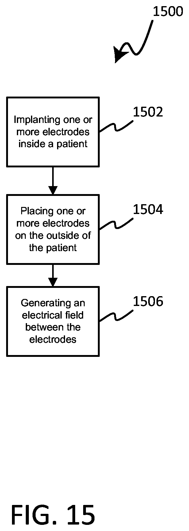
[0040] FIG. 15 is a flow chart depicting a method in accordance with various embodiments herein.
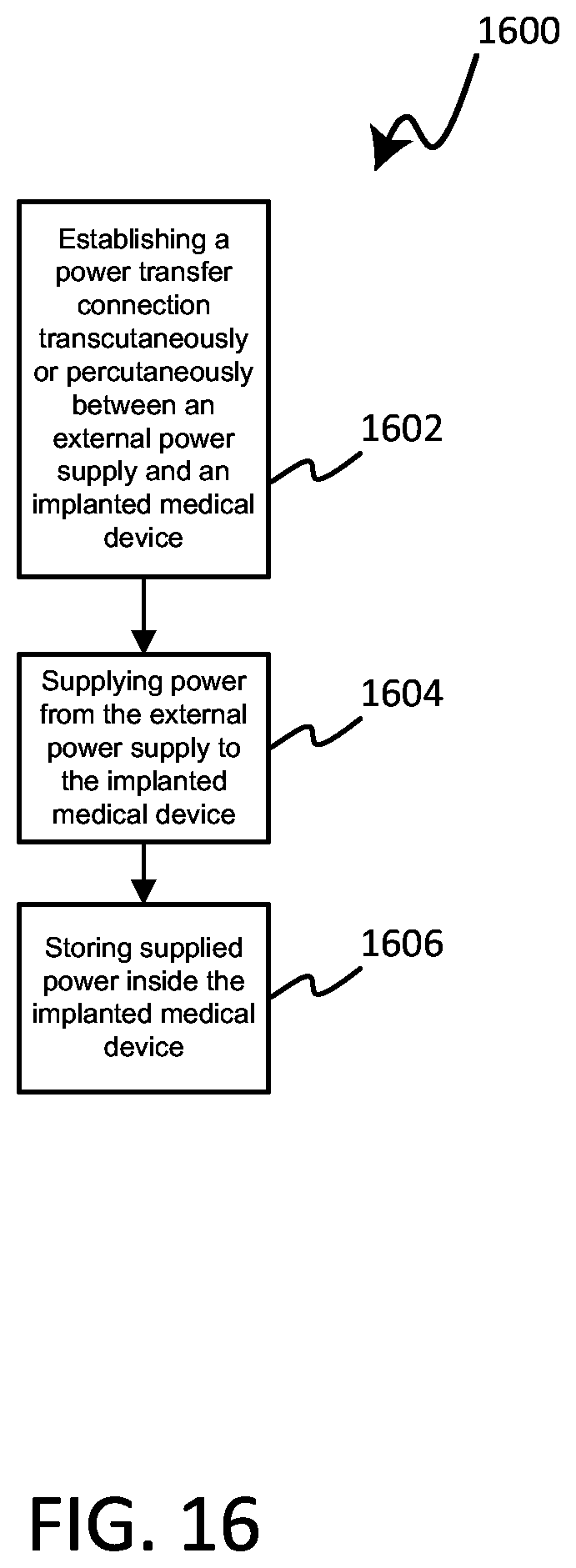
[0041] FIG. 16 is a flow chart depicting a method in accordance with various embodiments herein.
[0042] While embodiments are susceptible to various modifications and alternative forms, specifics thereof have been shown by way of example and drawings, and will be described in detail. It should be understood, however, that the scope herein is not limited to the particular aspects described. On the contrary, the intention is to cover modifications, equivalents, and alternatives falling within the spirit and scope herein.
DETAILED DESCRIPTION
[0043] As referenced above, many cancerous tumors can result from unchecked rapid cellular division. Some traditional first-line therapies to treat cancerous tumors can include surgery, radiation therapy, and chemotherapy. However, many first-line therapies have undesirable concomitant side effects, such as fatigue, hair loss, immunosuppression, and long surgical recovery times, to name a few.
[0044] While not intending to be bound by theory, it is believed that electric fields can disrupt mitosis within a cancerous tumor, such as by interfering with the dipole alignment of key proteins involved in cellular division; tubulin and septin in particular. The polymerization of tubulin proteins that form microtubule spindle fibers can be disrupted, thus preventing the formation of spindle fibers required for chromosome separation. This can halt cellular division at the metaphase stage of mitosis. In some instances an electric field can halt polymerization of already growing spindle fibers, leading to incomplete spindles and unequal chromosome separation during anaphase, should the cell survive that long. In each case, halting microtubule spindle formation and unequal chromosome separation during anaphase caused by incomplete polymerization of microtubules, can result in apoptosis (i.e., programmed cell death). It is also believed that alternating electric fields can lead to increased electric field density near the cleavage furrow of the dividing cells during telophase. An increased electric field density in the region of the cleavage furrow can result in dielectrophoresis of charged macromolecules, such as proteins and nucleic acids, toward the high electric field density at the furrow. The unequal concentration of key macromolecules required for cellular division at the site of the cleavage furrow can disrupt the final separation of the sister cells during telophase and eventually lead to apoptosis.
[0045] Various embodiments disclosed herein include a medical device system that can generate an electric field for treatment of cancer that can include, or can control, at least one implanted electrode and at least one electrode that is external to the patient's body. Internal electrodes can be advantageous as they can be positioned close to a treatment area (such as a cancerous tumor) and deliver and/or sense an electric field without substantial intervening tissue that diminished field strength. External electrodes can be advantageous because they can be moved more easily than most internal electrodes allowing for changes to the positions of electrodes used to deliver and/or sense electric fields. Such movement of electrodes can be desirable to account for changes to a tumor that is being treated and to accommodate desired changes in the stimulation and/or sense vectors. By including both implanted and external electrodes, desirable aspects of each approach can be combined to deliver electrical stimulation with high field strength to the desired treatment site while allowing for electrodes to be moved to change vectors as desired.
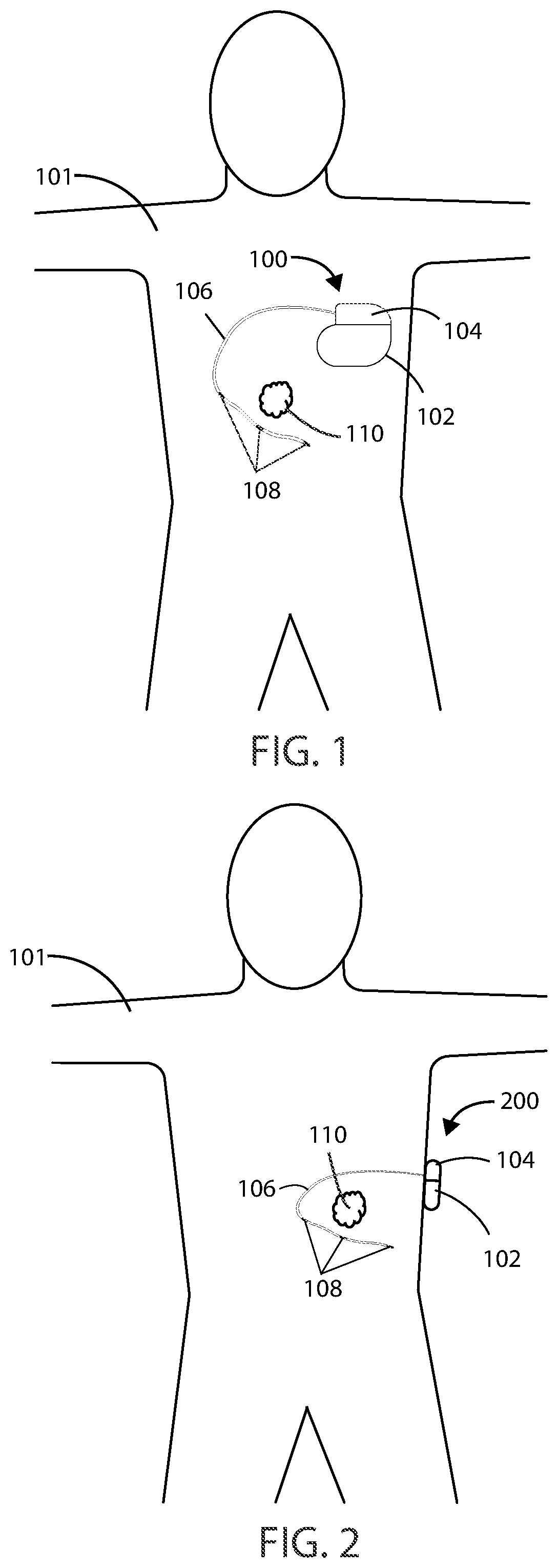
[0046] Referring now to FIG. 1, a schematic view is shown of a medical device 100 in accordance with various embodiments herein. The medical device 100 can be implanted entirely within the body of a patient 101 at or near the site of a cancerous tumor 110 located within a bodily tissue. Various implant sites can be used including areas such as in the limbs, the upper torso, the abdominal area, the head, and the like.
[0047] Referring now to FIG. 2, another schematic view is shown of a medical device 200 in accordance with various embodiments herein. The medical device 200 can be external but can be connected to an element, such as leads, that are at least partially implanted within the body of a patient 101. In some embodiments, the medical device 200 can be partially implanted and partially external to the body of a patient. In some embodiments, the medical device 200 can include a transcutaneous or percutaneous connection between components disposed internal to the body and external to the body. In various embodiments, the medical device system described herein can include an implanted medical device 100 and an external medical device 200. In other embodiments, the medical device system described herein can include a partially implanted medical device.
[0048] An implanted portion of a medical device system, such as an implanted medical device 100 or portion thereof, can wirelessly communicate patient identification data, diagnostic information, electric field data, physiological parameters, software updates, and the like with a fully or partially external portion of a medical device 200 over a wireless connection. Implanted medical device 100 can also wirelessly communicate with an external device configured to wirelessly charge the medical device utilizing inductance, radio frequency, and acoustic energy transfer techniques, and the like.
[0049] In some embodiments, a portion of a medical device or system can be entirely implanted and a portion of the medical device can be entirely external. For example, in some embodiments, one or more electrodes or leads can be entirely implanted within the body, whereas the portion of the medical device that generates an electric field, such as an electric field generator, can be entirely external to the body. It will be appreciated that in some embodiments described herein, the electric field generators described can include many of the same components as and can be configured to perform many of the same functions as a pulse generator. In embodiments where a portion of a medical device is entirely implanted and a portion of the medical device is entirely external, the portion of the medical device that is entirely external can communicate wirelessly with the portion of the medical device that is entirely internal. However, in other embodiments a wired connection can be used for the implanted portion to communication with the external portion.
[0050] The implanted medical device 100 and/or the medical device 200 can include a housing 102 and a header 104 coupled to the housing 102. Various materials can be used to form the housing 102. In some embodiments, the housing 102 can be formed of a material such as a metal, ceramic, polymer, composite, or the like. In some embodiments, the housing 102, or one or more portions thereof, can be formed of titanium. The header 104 can be formed of various materials, but in some embodiments the header 104 can be formed of a translucent polymer such as an epoxy material. In some embodiments the header 104 can be hollow. In other embodiments the header 104 can be filled with components and/or structural materials such as epoxy or another material such that it is non-hollow.
[0051] In some embodiments where a portion of the medical device 100 or 200 is partially external, the header 104 and housing 102 can be surrounded by a protective casing made of durable polymeric material. In other embodiments, where a portion of a device is partially external, the header 104 and housing 102 can be surrounded by a protective casing made of one or more of a polymeric material, metallic material, and/or glass material.
[0052] The header 104 can be coupled to one or more leads 106. The header 104 can serve to provide fixation of the proximal end of one or more leads 106 and electrically couple the one or more leads 106 to one or more components within the housing 102. The one or more leads 106 can include one or more electrodes 108 disposed along the length of the electrical leads 106. In some embodiments, electrodes 108 can include electric field generating electrodes and in other embodiments electrodes 108 can include electric field sensing electrodes. In some embodiments, leads 106 can include both electric field generating and electric field sensing electrodes. In other embodiments, leads 106 can include any number of electrodes that are both electric field sensing and electric field generating. The leads 106 can include one or more conductors therein, such as metal wires, to provide electrical communication between the electrodes and a proximal end (or plug) of the lead. The wires can exist as single strands or fibers or can be multifibrillar such as a cable. The leads 106 can include a shaft, typically formed of a polymeric material or another non-conductive material, within which the conductors therein can pass. The proximal end of the leads 106 can be inserted into the header 104, thereby providing electrical communication between the electrodes 108 and the components inside the housing 102. It will be appreciated that while many embodiments of medical devices herein are designed to function with leads, leadless medical devices that generate electrical fields are also contemplated herein.
[0053] In various embodiments, the electrodes 108 can be positioned around or adjacent to a tumor 110, such as a cancerous tumor. The tumor 110 can be positioned within an electric field generated by the electrodes 108.
[0054] The electric fields generated by the implanted medical device 100 and/or the medical device 200 can vary. In some embodiments, the implanted medical device 100 and/or the medical device 200 can generate one or more electric fields at frequencies selected from a range of between 10 kHz to 1 MHz.
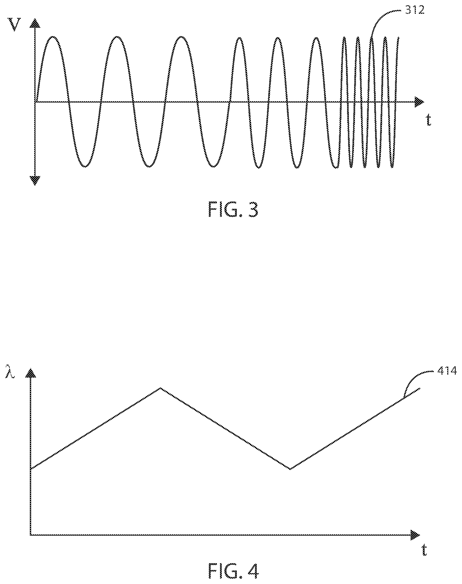
[0055] In some embodiments, an electric field can be applied to the site of a cancerous tumor at a specific frequency or constant frequency range. However, in some embodiments, an electric field can be applied to the site of a cancerous tumor by sweeping through a range of frequencies. As one example, referring now to FIG. 3, exemplary plot 312 shows an alternating electric field, delivered by the electrodes 108, where the frequency increases over time. Similarly, FIG. 4 shows the change in frequency as a function of time in exemplary plot 414 during a programmed therapy parameter. In some embodiments, a frequency sweep can include sweeping from a minimum frequency up to a maximum frequency. In some embodiments, a frequency sweep can include sweeping from a maximum frequency down to a minimum frequency. In other embodiments, sweeping from a minimum frequency up to a maximum frequency and sweeping from the maximum frequency down to the minimum frequency can be repeated as many times as desired throughout the duration of the delivery of the electric field from the electric field generating circuit.
[0056] As therapy progresses during a frequency sweep, it may be desired to alternate between frequency ranges so that as the cells within a population change in size and number in response to therapy, more cells can be targeted. For example, in some embodiments, a frequency sweep can include alternating between a first frequency sweep covering a range of about 100 kHz to 300 kHz and a second frequency sweep covering a range about 200 kHz to 500 kHz. It will be appreciated that sweeping through a first and second frequency range as described can be performed indefinitely throughout the course of the therapy. In some embodiments, the second frequency sweep (range) can be at higher frequencies than the first frequency sweep (range). In some embodiments, the first frequency sweep (range) can be at higher frequencies than the second frequency sweep (range).
[0057] Frequency ranges for the first and second frequency ranges can be any range including specific frequencies recited above or below, provided that the lower end of each range is a value less than the upper end of each range. At times, it may be beneficial to have some amount of overlap between the frequency range of the first and second frequency sweep.
Medical Devices and Systems
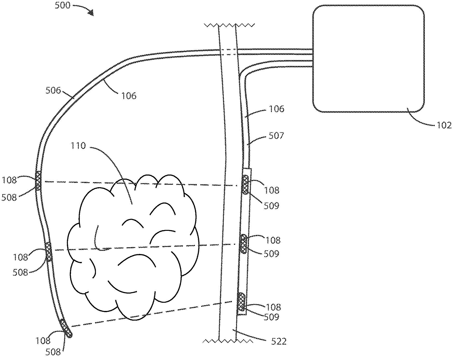
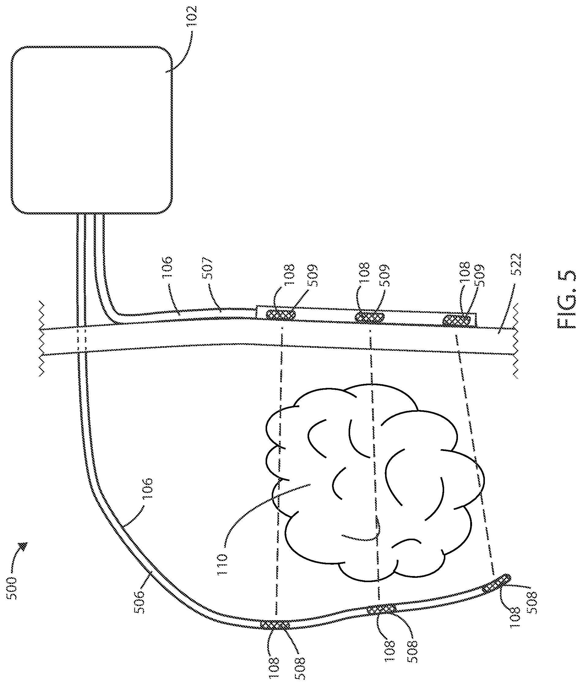
[0058] As described above, there can be various advantages associated with using combinations of implanted and external electrodes for delivery and/or sensing electrical fields. Referring now to FIG. 5, a schematic diagram of a medical device 500 is shown in accordance with the embodiments herein. The medical device 500 can include housing 102, one or more leads 106, at least one electric field generating circuit, and control circuitry. The electric field generating circuit can be disposed within the housing 102. The electric field generating circuit can be configured to generate one or more electric fields. The control circuitry can be in communication with the electric field generating circuit. The control circuitry can be configured to control delivery of the one or more electric fields from the electric field generating circuit. The control circuitry can cause the electric field generating circuit to generate one or more electric fields, such as at frequencies selected from a range between 10 kHz to 1 MHz, as further discussed below.
[0059] The leads 106 can include one or more electrodes such as electrodes 108 disposed along the length of the leads 106. In various embodiments, the electrodes 108 can deliver the electric fields to the site of a tumor, such as a cancerous tumor, within the patient. In some embodiments, the electrodes 108 can include electric field generating electrodes and, in other embodiments, the electrodes 108 can include electric field sensing electrodes. In some embodiments, the leads 106 can include both electric field generating and electric field sensing electrodes. In various embodiments, at least one electrode is configured to be implanted within the patient and at least one electrode is configured to be external to the patient. In various embodiments, one or more leads 106 can be implanted leads 506, and one or more leads 106 can be external leads 507. In various embodiments, one or more electrodes 108 can be implanted electrodes 508, and one or more electrodes 108 can be external electrodes 509. In some embodiments, at least two electrodes 508 are configured to be implanted and at least two electrodes 509 are configured to be external.
[0060] The proximal ends (or plugs) of leads 106 can be disposed within the header 104. The distal ends of electrical leads 106 can surround a tumor 110 such that the electrodes 108 are brought into proximity of the tumor 110. In some embodiments, the leads 106 can be positioned within the vasculature such that electrodes 108 are adjacent to or positioned within the tumor 110. However, it will be appreciated that leads 106 can be disposed in various places within or around the tumor 110. In some embodiments, the leads 106 can pass directly through the tumor 110.
[0061] In some embodiments, the leads 106 can include one or more tracking markers along the length of the lead for use in determining the precise location of the electrodes relative to the tumor. In some embodiments, the one or more tracking markers can be disposed directly distal or directly proximal to the one or more electrodes disposed on the lead. In some embodiments, the tracking markers can be formed from a magnetic material. In some embodiments, the tracking markers can be formed from a radiographic material. In some embodiments, the tracking markers can be formed from a fluorographic material.
[0062] It will be appreciated that a plurality of electric field vectors can be utilized between various combinations of electrodes 108 disposed along leads 106 to create an electric field. For example, one or more electric field vectors can be generated between the most proximal electrodes 108 on the two leads 106. Similarly, one or more electric field vectors can be generated between the distal most electrodes 108 on the two leads 106. It will also be appreciated that one or more electric field vectors can be generated between any combination of electrodes 108. In some embodiments, one or more electric field vectors can be generated between any combination of electrodes 108 and the housing 102 of the medical device 500. In some embodiments, the electric fields are delivered across at least one vector including both an implanted electrode and an external electrode. In various embodiments, the electric field strength can be greater at the site of the electrode 108 that is configured to be non-implanted (external) than at the site of the electrode 108 that is configured to be implanted, such as to account for the implanted electrode 108 being located closer to the tumor 110.
[0063] It will be appreciated that one or more unipolar or multipolar leads can be used in accordance with the embodiments herein. In some embodiments, a combination of unipolar and multipolar leads can be used. In other embodiments, a circular lead, clamp lead, cuff lead, paddle lead, or patch lead can be used.
[0064] In various embodiments, a lead 106 can provide electrical communication between the control circuitry and the implanted electrode 108, and a second lead 106 can provide electrical communication between the control circuitry and the external electrode 108. In some embodiments, a lead 106 can be a percutaneous lead 106, such as a lead that extends through or across the skin 522 of the patient. The tissue designated by reference number 522 can include one or more of the epidermis, dermis, hypodermis, and/or other tissue beneath those layers. The implanted electrodes 108 can be disposed on a percutaneous lead 106.
[0065] In some embodiments, exposing the tumor 110 to an electric field can shrink or move the tumor 110, such that the original position of the electrodes 108 is no longer the most efficient or most desired. In such embodiments, the external electrodes 509 on the external lead 507 can be easily moved to account for the changes of the tumor 110.
[0066] In comparing FIG. 5 to FIG. 6, it can be seen that the tumor 110 has shrunk, such as a result of treatment. As such, the external electrodes 509 on an outside surface of the body of the patient have been moved to a more efficient or desirable position.
[0067] In reference now to FIG. 6, it can be seen that the external electrodes 509 have been moved to affect the electrical field. In various embodiments, the electrical field between the electrodes 108 can be ceased, then one or more external electrodes 509 can be moved. After the external electrodes 509 have been repositioned, the electrical field can be generated once again to resume treatment. In many cases external electrodes 509 are easily moved or repositioned compared to implanted electrodes 508.
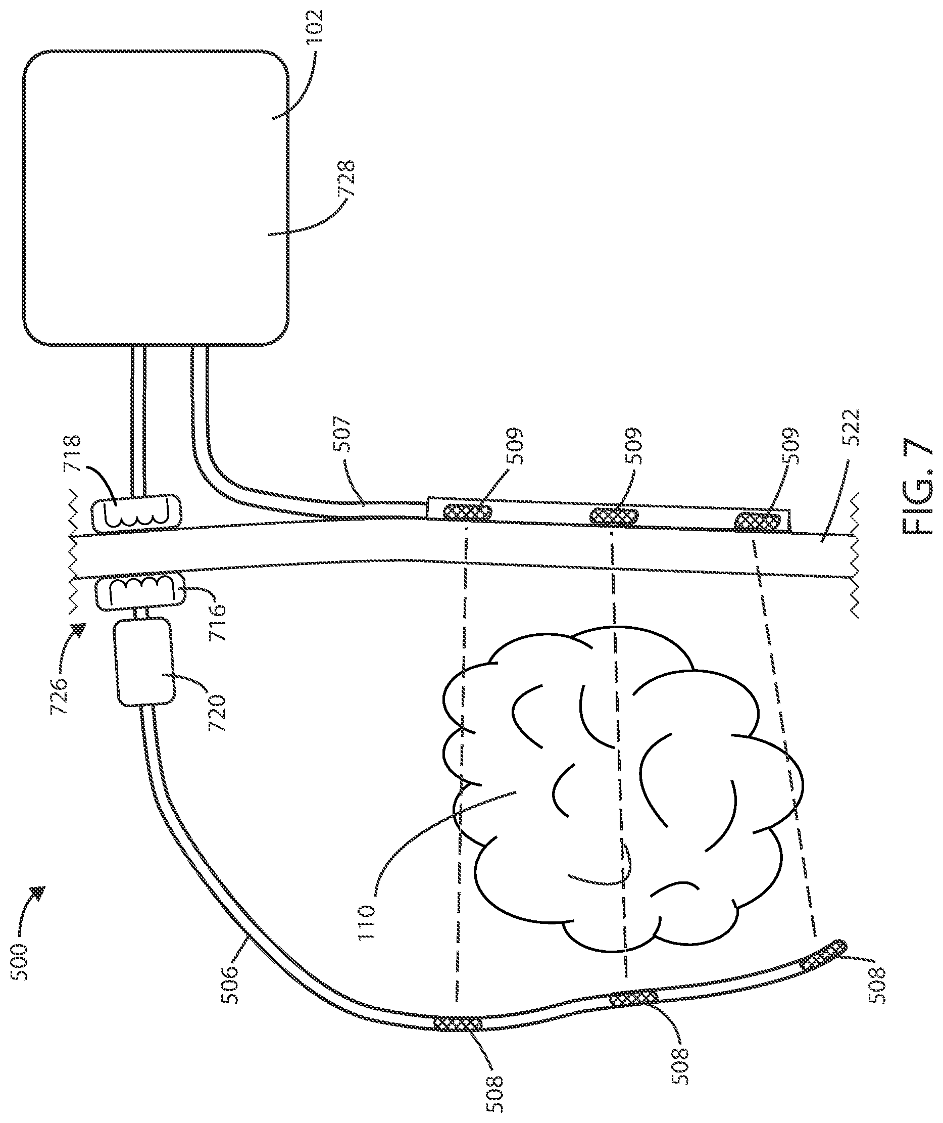
[0068] In reference now to FIG. 7, a schematic view of a medical device 500 is shown in accordance with various embodiments herein. In some embodiments, the implanted lead 506 can terminate within the patient, such that the lead 106 does not extend through or across the patient's skin 522.
[0069] In some embodiments, a wireless power transfer connection 726 can be established transcutaneously between an external power supply 728, such as a power supply within the housing 102, and an implanted lead 506. In some embodiments, the medical device 500 can include an inductive power transfer link, including paired internal 716 and external 718 inductors to transfer power from outside of the body to an implanted component of the system. The inductive power transfer link can allow for a transfer of power from an external power supply 728 to an internal control component 720, which in turn can cause an electrical field to be generated with the implanted electrodes 508 without puncturing the skin 522 or otherwise requiring a maintained opening or tunnel through the patient's skin 522. In some embodiments, the internal control component can include a battery or one or more capacitors to store enough energy to maintain delivering an electrical field for at least a period of time. In some embodiments, the internal control component includes one or more capacitors, but not a battery. In some embodiments, the internal control component 720 can include circuitry and components therein similar or the same as that described with respect to FIGS. 13 and 14 herein. In some embodiments, the transferred power provided from the external power supply 728 can be modulated to control the electrical field as provided through the implanted electrodes 508. For example, the transferred power can be used as a control signal to control aspects of electrical field generation including, but not limited to, frequency, duty cycle, electrical field strength, and the like.
[0070] Referring now to FIG. 8, a schematic view of a medical device 500 is shown in accordance with various embodiments herein. The medical device 500 can include an implanted medical device 100 and an external medical device 200. In some embodiments, the medical device 500 can include at least one implanted housing 818. The implanted housing 818 can define an interior volume. An electric field generating circuit and a control circuit can be disposed within the interior volume of the housing 818. In some embodiments, the implanted electrodes 508 can be disposed on a fully implanted lead 506, such as a lead 506 with both the proximal end and the distal end terminating within the patient's body.
[0071] The medical device 500 can further include at least one external housing 820. The external housing 820 can define an interior volume. A second electric field generating circuit and control circuit can be disposed within the interior volume of the housing 820.
[0072] In various embodiments, an implanted medical device 100, such as the implanted housing 818, can be configured to send a wireless signal for receipt by an external medical device 200, such as the external housing 820. Similarly, an external medical device 200, such as the external housing 820, can be configured to send a wireless signal for receipt by an implanted medical device 100, such as the implanted housing 818. In various embodiments, the wireless signal can include various information, such as information regarding charge level of a battery associated with the implanted cancer treatment device. Other information can also be transferred between the implanted device and the external device wirelessly, such as treatment parameters and sensor readings.
[0073] FIG. 9 shows a schematic view of a medical device 500 in accordance with various embodiments herein. The medical device 500 can include an implanted medical device 100 and an external medical device 200. In some embodiments, the medical device 500 can include two electric field generating circuits. The implanted medical device 100 can include a first electric field generating circuit and the external medical device 200 can include a second electric field generating circuit. In various embodiment, the implanted medical device 100 can be entirely located within the patient, and the external medical device 200 can be entirely located outside of the patient's body, such that no physical components extend through or across the patient's skin 522.
[0074] In some embodiments, the implanted medical device 100 can include two or more leads 506, and the external medical device 200 can include two or more leads 507. The leads 506 can include electrodes 508. The leads 507 can include electrodes 509. In some embodiments, the electric fields can be delivered across at least two vectors, such as first vector defined by a pair of electrodes 508 that are both implanted, and a second vector defined by a pair of electrodes 509 that are both external. In some embodiments, such as shown in FIG. 9, the electric fields along the two vectors can be substantially orthogonal to one another.
External Power Supply
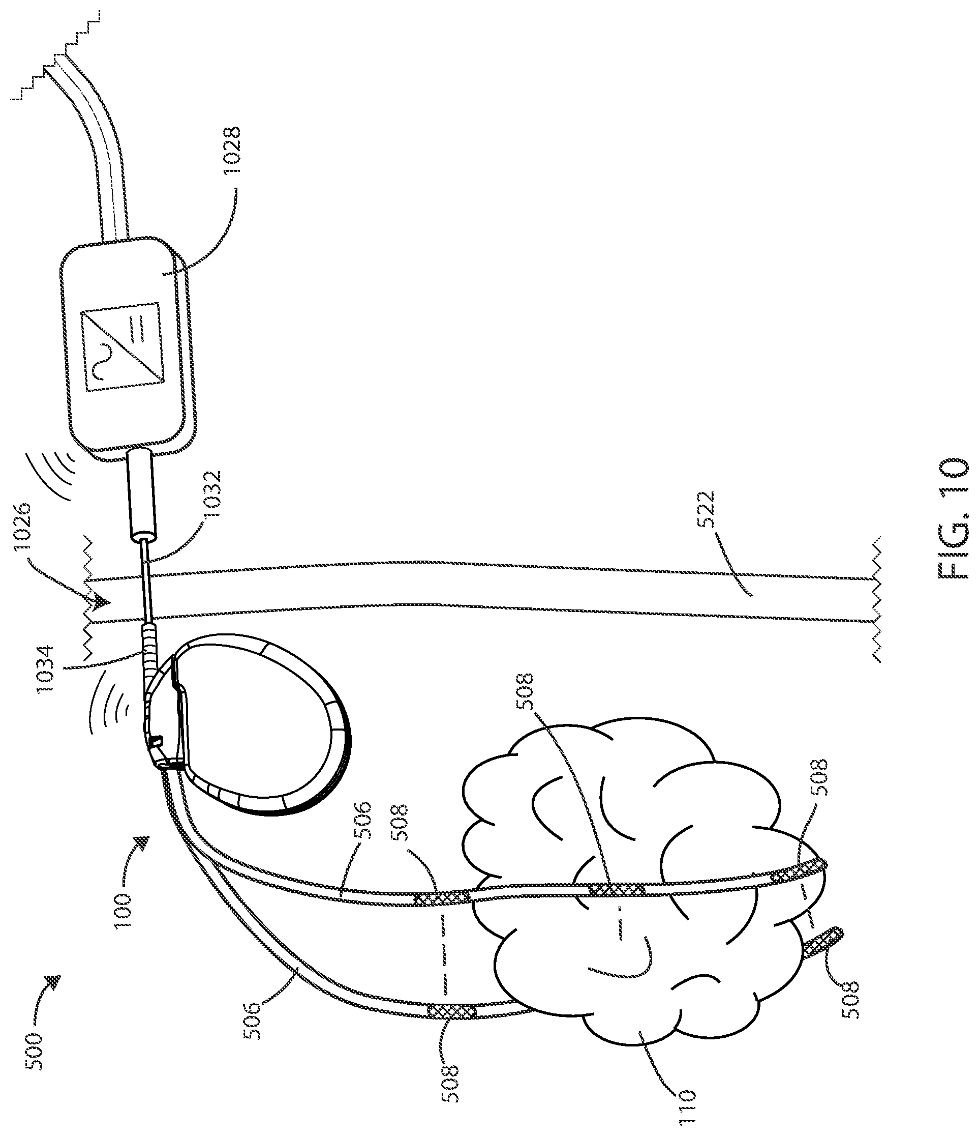
[0075] In some embodiments, a power transfer connection 1026 can be established transcutaneously or percutaneously between an external power supply 1028 and an implanted medical device 100. In reference now to FIG. 10, a schematic view of a medical device 500 is shown in accordance with various embodiments herein. In some embodiments, the medical device 500 can include an implanted medical device 100 and an external power supply 1028. The power can be supplied from the external power supply 1028 to the implanted medical device 100 through a power supply probe 1032, such as a needle. The external power supply 1028 can include the power supply probe 1032. The implanted medical device 100 can include a power connection receiver 1034.
[0076] In some embodiments, the power connection receiver 1034 can be configured to receive a portion of the power supply probe 1032, such as to transfer power or communication signals between the implanted device 100 and the external power supply 1028. Power can be supplied by the external power supply 1028 and stored inside the implanted medical device 100.
[0077] In various embodiments, establishing a power transfer connection 1026 percutaneously between the external power supply 1028 and the implanted device 100 can include inserting the power supply probe 1032 connected to the external power supply 1028 percutaneously into the power connection receiver 1034 connected to the implanted medical device 100. In various embodiments, power supplied from the external power supply 1028 can be modulated to control electric field generation by the implanted medical device 100.
[0078] Power supplied to the implanted medical device 100 can be stored in the implanted medical device 100, such as for usage at a future time. The power can be stored within the implanted medical device 100 such that the power transfer connection 1026 does not need to be maintained for the implanted medical device 100 to operate. The power transfer connection 1026 can be established when needed, such as to recharge a battery in the implanted medical device 100.
[0079] In some embodiments, the power supply probe 1032 can extend through the patient's skin 522 to insert into the power connection receiver 1034. In various embodiments, when the power supply probe 1032 is not connected to the power connection receiver 1034, the patient's skin 522 can heal and cover the power connection receiver 1034. In some embodiments, to reestablish the power transfer connection 1026, the power supply probe 1032 can puncture or penetrate through the patient's skin 522 and connect with the power connection receiver 1034.
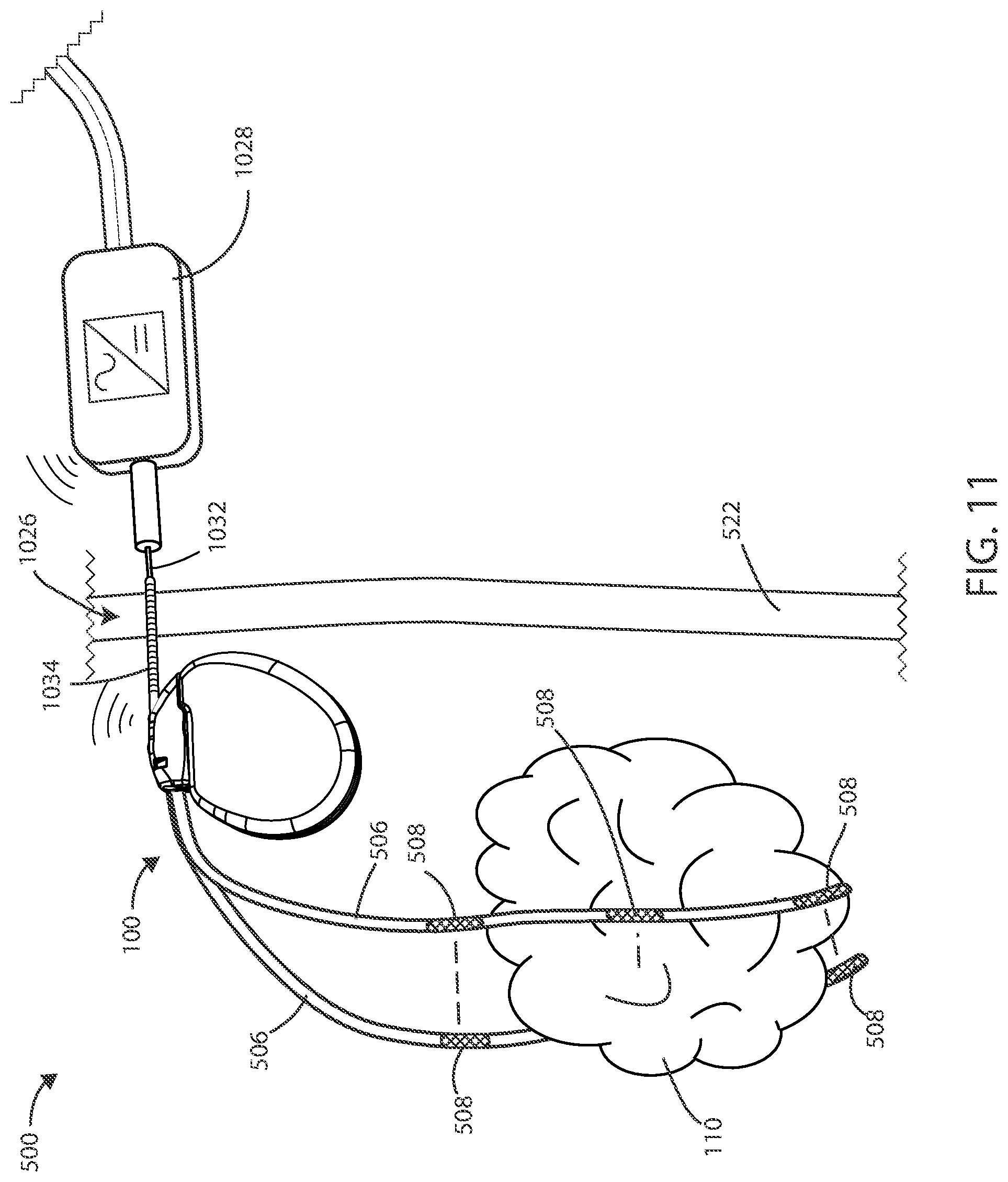
[0080] In reference now to FIG. 11, a schematic of a medical device 500 is shown in accordance with various embodiments. In some embodiments, the power connection receiver 1034 can extend through the skin 522, such that the power supply probe 1032 can connected with the power connection receiver 1034 without extending through the patient's skin 522 or without creating a new aperture in the patient's skin 522. In various embodiments, the external power supply 1028 can be in wireless communication with the implanted medical device 100, such as to relay information regarding battery charge status or treatment parameters.
[0081] In reference now to FIG. 12, a schematic of a medical device 500 is shown in accordance with various embodiments. The medical device 500 can include an external power supply 1028 and an implanted medical device 100. In some embodiments, the power transfer connection 1026 can include a transcutaneous inductive power transfer link 1236. In some embodiments, the power supplied from the external power supply 1028 can be modulated to control electric field generation by the implanted device 100.
[0082] Referring now to FIG. 13, a schematic cross-sectional view of medical device 1300 is shown in accordance with various embodiments herein. The housing 102 can define an interior volume 1302 that can be hollow and that in some embodiments is hermetically sealed off from the area 1304 outside of medical device 1300. In other embodiments the housing 102 can be filled with components and/or structural materials such that it is non-hollow. The medical device 1300 can include control circuitry 1306, which can include various components 1308, 1310, 1312, 1314, 1316, and 1318 disposed within housing 102. In some embodiments, these components can be integrated and in other embodiments these components can be separate. In yet other embodiments, there can be a combination of both integrated and separate components. The medical device 1300 can also include an antenna 1324, to allow for unidirectional or bidirectional wireless data communication, such as with an external device or an external power supply. In some embodiments, the components of medical device 1300 can include an inductive energy receiver coil (not shown) communicatively coupled or attached thereto to facilitate transcutaneous recharging of the medical device via recharging circuitry.
[0083] The various components 1308, 1310, 1312, 1314, 1316, and 1318 of control circuitry 1306 can include, but are not limited to, a microprocessor, memory circuit (such as random access memory (RAM) and/or read only memory (ROM)), recorder circuitry, controller circuit, a telemetry circuit, a power supply circuit (such as a battery), a timing circuit, and an application specific integrated circuit (ASIC), a recharging circuit, amongst others. Control circuitry 1306 can be in communication with an electric field generating circuit 1320 that can be configured to generate electric current to create one or more fields. The electric field generating circuit 1320 can be integrated with the control circuitry 1306 or can be a separate component from control circuitry 1306. Control circuitry 1306 can be configured to control delivery of electric current from the electric field generating circuit 1320. In some embodiments, the electric field generating circuit 1320 can be present in a portion of the medical device that is external to the body.
[0084] In some embodiments, the control circuitry 1306 can be configured to direct the electric field generating circuit 1320 to deliver an electric field via leads 106 to the site of a cancerous tumor located within a bodily tissue. In other embodiments, the control circuitry 1306 can be configured to direct the electric field generating circuit 1320 to deliver an electric field via the housing 102 of medical device 1300 to the site of a cancerous tumor located within a bodily tissue. In other embodiments, the control circuitry 1306 can be configured to direct the electric field generating circuit 1320 to deliver an electric field between leads 106 and the housing 102 of medical device 1300. In some embodiments, one or more leads 106 can be in electrical communication with the electric field generating circuit 1320.
[0085] In some embodiments, various components within medical device 1300 can include an electric field sensing circuit 1322 configured to generate a signal corresponding to sensed electric fields. Electric field sensing circuit 1322 can be integrated with control circuitry 1306 or it can be separate from control circuitry 1306.
[0086] Sensing electrodes can be disposed on or adjacent to the housing of the medical device, on one or more leads connected to the housing, on a separate device implanted near or in the tumor, or any combination of these locations. In some embodiments, the electric field sensing circuit 1322 can include a first sensing electrode 1332 and a second sensing electrode 1334. In other embodiments, the housing 102 itself can serve as a sensing electrode for the electric field sensing circuit 1322. The electrodes 1332 and 1334 can be in communication with the electric field sensing circuit 1322. The electric field sensing circuit 1322 can measure the electrical potential difference (voltage) between the first electrode 1332 and the second electrode 1334. In some embodiments, the electric field sensing circuit 1322 can measure the electrical potential difference (voltage) between the first electrode 1332 or second electrode 1334, and an electrode disposed along the length of one or more leads 106. In some embodiments, the electric field sensing circuit can be configured to measure sensed electric fields and to record electric field strength in V/cm.
[0087] It will be appreciated that the electric field sensing circuit 1322 can additionally measure an electrical potential difference between the first electrode 1332 or the second electrode 1334 and the housing 102 itself. In other embodiments, the medical device can include a third electrode 1336, which can be an electric field sensing electrode or an electric field generating electrode. In some embodiments, one or more sensing electrodes can be disposed along lead 106 and can serve as additional locations for sensing an electric field. Many combinations can be imagined for measuring electrical potential difference between electrodes disposed along the length of one or more leads 106 and the housing 102 in accordance with the embodiments herein.
[0088] In some embodiments, the one or more leads 106 can be in electrical communication with the electric field generating circuit 1320. The one or more leads 106 can include one or more electrodes 108, as shown in FIGS. 1 and 2. In some embodiments, various electrical conductors, such as electrical conductors 1326 and 1328, can pass from the header 104 through a feed-through structure 1330 and into the interior volume 1302 of medical device 1300. As such, the electrical conductors 1326 and 1328 can serve to provide electrical communication between the one or more leads 106 and control circuitry 1306 disposed within the interior volume 1302 of the housing 102.
[0089] In some embodiments, recorder circuitry can be configured to record the data produced by the electric field sensing circuit 1322 and record time stamps regarding the same. In some embodiments, the control circuitry 1306 can be hardwired to execute various functions, while in other embodiments the control circuitry 1306 can be directed to implement instructions executing on a microprocessor or other external computation device. A telemetry circuit can also be provided for communicating with external computation devices such as a programmer, a home-based unit, and/or a mobile unit (e.g. a cellular phone, personal computer, smart phone, tablet computer, and the like).
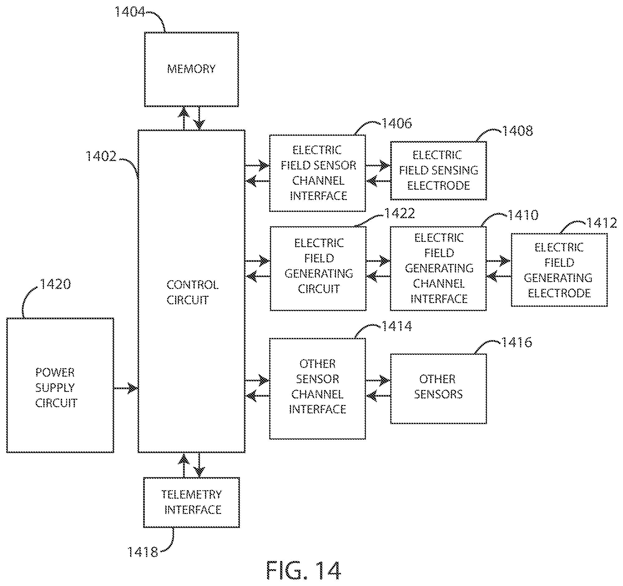
[0090] Elements of various embodiments of the medical devices described herein are shown in FIG. 14. However, it will be appreciated that some embodiments can include additional elements beyond those shown in FIG. 14. In addition, some embodiments may lack some elements shown in FIG. 14. The medical devices as embodied herein can gather information through one or more sensing channels and can output information through one or more field generating channels. A microprocessor 1402 can communicate with a memory 1404 via a bidirectional data bus. The memory 1404 can include read only memory (ROM) or random-access memory (RAM) for program storage and RAM for data storage. The microprocessor 1402 can also be connected to a telemetry interface 1418 for communicating with external devices such as a programmer, a home-based unit and/or a mobile unit (e.g. a cellular phone, personal computer, smart phone, tablet computer, and the like) or directly to the cloud or another communication network as facilitated by a cellular or other data communication network. The medical device can include a power supply circuit 1420. In some embodiments, the medical device can include an inductive energy receiver coil interface (not shown) communicatively coupled or attached thereto to facilitate transcutaneous recharging of the medical device.
[0091] The medical device can include one or more electric field sensing electrodes 1408 and one or more electric field sensor channel interfaces 1406 that can communicate with a port of microprocessor 1402. The medical device can also include one or more electric field generating circuits 1422, one or more electric field generating electrodes 1412, and one or more electric field generating channel interfaces 1410 that can communicate with a port of microprocessor 1402. The medical device can also include one or more physiological sensors, respiration sensors, or chemical sensors 1416 and one or more physiological/respiration/chemical sensor channel interfaces 1414 that can communicate with a port of microprocessor 1402. The channel interfaces 1406, 1410, and 1414 can include various components such as analog-to-digital converters for digitizing signal inputs, sensing amplifiers, registers which can be written to by the control circuitry in order to adjust the gain and threshold values for the sensing amplifiers, source drivers, modulators, demodulators, multiplexers, and the like.
[0092] In some embodiments, the physiological sensors can include sensors that monitor temperature, blood flow, blood pressure, and the like. In some embodiments, the respiration sensors can include sensors that monitor respiration rate, respiration peak amplitude, and the like. In some embodiments, the chemical sensors can measure the quantity of an analyte present in a treatment area about the sensor, including but not limited to analytes such as of blood urea nitrogen, creatinine, fibrin, fibrinogen, immunoglobulins, deoxyribonucleic acids, ribonucleic acids, potassium, sodium, chloride, calcium, magnesium, lithium, hydronium, hydrogen phosphate, bicarbonate, and the like. However, many other analytes are also contemplated herein. Exemplary chemical/analyte sensors are disclosed in commonly owned U.S. Pat. No. 7,809,441 to Kane et al., and which is hereby incorporated by reference in its entirety.
[0093] Although the physiological, respiration, or chemical sensors 1416 are shown as part of a medical device in FIG. 14, it is realized that in some embodiments one or more of the physiological, respiration, or chemical sensors could be physically separate from the medical device. In various embodiments, one or more of the physiological, respiration, or chemical sensors can be within another implanted medical device communicatively coupled to a medical device via telemetry interface 1418. In yet other embodiments, one or more of the physiological, respiration, or chemical sensors can be external to the body and coupled to a medical device via telemetry interface 1418.
Methods
[0094] In reference now to FIG. 15, a flow chart depicting a method of treating a cancerous tumor is shown. The method 1500 of treating a tumor can include implanting one or more electrodes inside a body of a patient with a tumor, step 1502. The method 1500 can include placing one or more external electrodes on the outside surface of the patient's body, step 1504. The method 1500 can further include generating an electrical field between the electrodes, step 1506. In various embodiments, the electric field can have frequencies within a range of between 10 kHz to 1 MHz.
[0095] In some embodiments, the method 1500 can include ceasing or stopping the generation of the electrical field between the electrodes. In some embodiments, the method 1500 can further include moving the one or more electrodes on an outside surface of the patient's body, such as in response to the tumor changing or modifying the treatment. The method 1500 can also include generating an electrical field between at least one pair of electrodes, such as after the one or more external electrodes have been moved. In various embodiments, the electric field can have frequencies within a range of between 10 kHz to 1 MHz.
[0096] In various embodiments, the method 1500 can include generating electrical fields between respective electrodes of at least two electrode pairs. In some embodiments, a first electrode pair includes two implanted electrodes and a second electrode pair includes two external electrodes.
[0097] Referring now to FIG. 16, a flow chart depicting a method 1600 of providing power to an implanted medical device is shown. The method 1600 for providing power to an implanted medical device can include establishing a power transfer connection, step 1602. In various embodiments, the power transfer connection can be transcutaneously or percutaneous between an external power supply and an implanted medical device.
[0098] The method 1600 can include supplying power from the external power supply to the implanted medical device through a power supply probe, step 1604. In some embodiments, the power supplied from the external power supply can be modulated to control electric field generation by the implanted medical device. The method 1600 can include storing the supplied power inside the implanted medical device, step 1606.
[0099] In some embodiments, establishing a power transfer connection percutaneously between an external power supply and the implanted medical device can include inserting a power supply probe connected to the external power supply percutaneously into a power connection receiver connected to the implanted medical device, such as shown in FIGS. 10-11. In some embodiments, establishing a power transfer connection transcutaneously between an external power supply and the implanted medical device can include establishing a percutaneous inductive power transfer link, such as shown in FIG. 12. In some embodiments, the implanted medical device can be configured to send a wireless signal for receipt by a secondary device outside of the body. The signal can include information regarding charge level of a battery associated with the implanted medical device.
[0100] In various embodiments, the implanted medical device can include at least one electric field generating circuit configured to generate one or more electric fields; control circuitry in communication with the electric field generating circuit, and an interface to electrically connect to two or more electrodes to deliver the electric fields to the site of a cancerous tumor within a patient. In various embodiments, the control circuitry can be configured to control delivery of the one or more electric fields from the at least one electric field generating circuit.
Electrical Stimulation Parameters
[0101] In various embodiments, systems or device herein (or components thereof, such as control circuitry) can be configured to direct an electric field generating circuit to deliver an electric field using one or more frequencies selected from a range of between 10 kHz to 1 MHz. In some embodiments, the control circuitry can be configured to direct the electric field generating circuit to deliver an electric field at one or more frequencies selected from a range of between 100 kHz to 500 kHz. In some embodiments, the control circuitry can be configured to direct the electric field generating circuit to deliver an electric field at one or more frequencies selected from a range of between 100 kHz to 300 kHz. In some embodiments, the control circuitry can be configured to direct the electric field generating circuit to periodically deliver an electric field using one or more frequencies greater than 1 MHz.
[0102] In some embodiments, the electric field can be effective in disrupting cellular mitosis in cancerous cells. The electric field can be delivered to the site of a cancerous tumor along more than one vector. In some examples, the electric field can be delivered along at least one vector, including at least one of the lead electrodes. In some embodiments, at least two vectors with spatial diversity between the two vectors can be used. The vectors can be spatially separated (e.g., the vectors can be disposed at an angle with respect to one another) by at least about 10, 20, 30, 40, 50, 60, 70, 80 or 90 degrees.
[0103] A desired electric field strength can be achieved by delivering an electric current between two electrodes. The specific current and voltage at which the electric field is delivered can vary and can be adjusted to achieve the desired electric field strength at the site of the tissue to be treated. In some embodiments, the control circuitry can be configured to direct the electric field generating circuit to deliver an electric field using currents ranging from 1 mAmp to 1000 mAmp to the site of a cancerous tumor. In some embodiments, the control circuitry can be configured to direct the electric field generating circuit to deliver an electric field using currents ranging from 20 mAmp to 500 mAmp to the site of a cancerous tumor. In some embodiments, the control circuitry can be configured to direct the electric field generating circuit to deliver an electric field using currents ranging from 30 mAmp to 300 mAmp to the site of a cancerous tumor.
[0104] In some embodiments, the control circuitry can be configured to direct the electric field generating circuit to deliver an electric field using currents including 1 mAmp, 2 mAmp, 3 mAmp, 4 mAmp, 5 mAmp, 6 mAmp, 7 mAmp, 8 mAmp, 9 mAmp, 10 mAmp, 15 mAmp, 20 mAmp, 25 mAmp, 30 mAmp, 35 mAmp, 40 mAmp, 45 mAmp, 50 mAmp, 60 mAmp, 70 mAmp, 80 mAmp, 90 mAmp, 100 mAmp, 125 mAmp, 150 mAmp, 175 mAmp, 200 mAmp, 225 mAmp, 250 mAmp, 275 mAmp, 300 mAmp, 325 mAmp, 350 mAmp, 375 mAmp, 400 mAmp, 425 mAmp, 450 mAmp, 475 mAmp, 500 mAmp, 525 mAmp, 550 mAmp, 575 mAmp, 600 mAmp, 625 mAmp, 650 mAmp, 675 mAmp, 700 mAmp, 725 mAmp, 750 mAmp, 775 mAmp, 800 mAmp, 825 mAmp, 850 mAmp, 875 mAmp, 900 mAmp, 925 mAmp, 950 mAmp, 975 mAmp, or 1000 mAmp. It will be appreciated that the control circuitry can be configured to direct the electric field generating circuit 1320 to deliver an electric field at a current falling within a range, wherein any of the forgoing currents can serve as the lower or upper bound of the range, provided that the lower bound of the range is a value less than the upper bound of the range.
[0105] In some embodiments, the control circuitry can be configured to direct the electric field generating circuit to deliver an electric field using voltages ranging from 1 V.sub.rms to 50 V.sub.rms to the site of a cancerous tumor. In some embodiments, the control circuitry can be configured to direct the electric field generating circuit to deliver an electric field using voltages ranging from 5 V.sub.rms to 30 V.sub.rms to the site of a cancerous tumor. In some embodiments, the control circuitry can be configured to direct the electric field generating circuit to deliver an electric field using voltages ranging from 10 V.sub.rms to 20 V.sub.rms to the site of a cancerous tumor.
[0106] In some embodiments, the control circuitry can be configured to direct the electric field generating circuit 320 to deliver an electric field using one or more voltages including 1 V.sub.rms, 2 V.sub.rms, 3 V.sub.rms, 4 V.sub.rms, 5 V.sub.rms, 6 V.sub.rms, 7 V.sub.rms, 8 V.sub.rms, 9 V.sub.rms, 10 V.sub.rms, 15 V.sub.rms, 20 V.sub.rms, 25 V.sub.rms, 30 V.sub.rms, 35 V.sub.rms, 40 V.sub.rms, 45 V.sub.rms, or 50 V.sub.rms. It will be appreciated that the control circuitry can be configured to direct the electric field generating circuit to deliver an electric field using a voltage falling within a range, wherein any of the forgoing voltages can serve as the lower or upper bound of the range, provided that the lower bound of the range is a value less than the upper bound of the range.
[0107] In some embodiments, the control circuitry can be configured to direct the electric field generating circuit to deliver and electric field using one or more frequencies including 10 kHz, 20 kHz, 30 kHz, 40 kHz, 50 kHz, 60 kHz, 70 kHz, 80 kHz, 90 kHz, 100 kHz, 125 kHz, 150 kHz, 175 kHz, 200 kHz, 225 kHz, 250 kHz, 275 kHz, 300 kHz, 325 kHz, 350 kHz, 375 kHz, 400 kHz, 425 kHz, 450 kHz, 475 kHz, 500 kHz, 525 kHz, 550 kHz, 575 kHz, 600 kHz, 625 kHz, 650 kHz, 675 kHz, 700 kHz, 725 kHz, 750 kHz, 775 kHz, 800 kHz, 825 kHz, 850 kHz, 875 kHz, 900 kHz, 925 kHz, 950 kHz, 975 kHz, 1 MHz. It will be appreciated that the electric field generating circuit can deliver an electric field using a frequency falling within a range, wherein any of the foregoing frequencies can serve as the upper or lower bound of the range, provided that the upper bound is greater than the lower bound.
[0108] In some embodiments, the control circuitry can be configured to direct the electric field generating circuit to generate one or more applied electric field strengths selected from a range of between 0.25 V/cm to 1000 V/cm. In some embodiments, the control circuitry can be configured to direct the electric field generating circuit to generate one or more applied electric field strengths of greater than 3 V/cm. In some embodiments, the control circuitry can be configured to direct the electric field generating circuit to generate one or more applied electric field strengths selected from a range of between 1 V/cm to 10 V/cm. In some embodiments, the control circuitry can be configured to direct the electric field generating circuit to generate one or more applied electric field strengths selected from a range of between 3 V/cm to 5 V/cm.
[0109] In other embodiments, the control circuitry can be configured to direct the electric field generating circuit to generate one or more applied electric field strengths including 0.25 V/cm, 0.5 V/cm, 0.75 V/cm, 1.0 V/cm, 2.0 V/cm, 3.0 V/cm, 5.0 V/cm, 6.0 V/cm, 7.0 V/cm, 8.0 V/cm, 9.0 V/cm, 10.0 V/cm, 20.0 V/cm, 30.0 V/cm, 40.0 V/cm, 50.0 V/cm, 60.0 V/cm, 70.0 V/cm, 80.0 V/cm, 90.0 V/cm, 100.0 V/cm, 125.0 V/cm, 150.0 V/cm, 175.0 V/cm, 200.0 V/cm, 225.0 V/cm, 250.0 V/cm, 275.0 V/cm, 300.0 V/cm, 325.0 V/cm, 350.0 V/cm, 375.0 V/cm, 400.0 V/cm, 425.0 V/cm, 450.0 V/cm, 475.0 V/cm, 500.0 V/cm, 600.0 V/cm, 700.0 V/cm, 800.0 V/cm, 900.0 V/cm, 1000.0 V/cm. It will be appreciated that the electric field generating circuit can generate an electric field having a field strength at a treatment site falling within a range, wherein any of the foregoing field strengths can serve as the upper or lower bound of the range, provided that the upper bound is greater than the lower bound.
[0110] It should be noted that, as used in this specification and the appended claims, the singular forms "a," "an," and "the" include plural referents unless the content clearly dictates otherwise. It should also be noted that the term "or" is generally employed in its sense including "and/or" unless the content clearly dictates otherwise.
[0111] It should also be noted that, as used in this specification and the appended claims, the phrase "configured" describes a system, apparatus, or other structure that is constructed or configured to perform a particular task or adopt a particular configuration. The phrase "configured" can be used interchangeably with other similar phrases such as arranged and configured, constructed and arranged, constructed, manufactured and arranged, and the like.
[0112] All publications and patent applications in this specification are indicative of the level of ordinary skill in the art to which this invention pertains. All publications and patent applications are herein incorporated by reference to the same extent as if each individual publication or patent application was specifically and individually indicated by reference.
[0113] As used herein, the recitation of numerical ranges by endpoints shall include all numbers subsumed within that range (e.g., 2 to 8 includes 2.1, 2.8, 5.3, 7, etc.).
[0114] The headings used herein are provided for consistency with suggestions under 37 CFR 1.77 or otherwise to provide organizational cues. These headings shall not be viewed to limit or characterize the invention(s) set out in any claims that may issue from this disclosure. As an example, although the headings refer to a "Field," such claims should not be limited by the language chosen under this heading to describe the so-called technical field. Further, a description of a technology in the "Background" is not an admission that technology is prior art to any invention(s) in this disclosure. Neither is the "Summary" to be considered as a characterization of the invention(s) set forth in issued claims.
[0115] The embodiments described herein are not intended to be exhaustive or to limit the invention to the precise forms disclosed in the following detailed description. Rather, the embodiments are chosen and described so that others skilled in the art can appreciate and understand the principles and practices. As such, aspects have been described with reference to various specific and preferred embodiments and techniques. However, it should be understood that many variations and modifications may be made while remaining within the spirit and scope herein.
* * * * *
D00000
D00001
D00002
D00003
D00004
D00005
D00006
D00007
D00008
D00009
D00010
D00011
D00012
D00013
D00014
XML
uspto.report is an independent third-party trademark research tool that is not affiliated, endorsed, or sponsored by the United States Patent and Trademark Office (USPTO) or any other governmental organization. The information provided by uspto.report is based on publicly available data at the time of writing and is intended for informational purposes only.
While we strive to provide accurate and up-to-date information, we do not guarantee the accuracy, completeness, reliability, or suitability of the information displayed on this site. The use of this site is at your own risk. Any reliance you place on such information is therefore strictly at your own risk.
All official trademark data, including owner information, should be verified by visiting the official USPTO website at www.uspto.gov. This site is not intended to replace professional legal advice and should not be used as a substitute for consulting with a legal professional who is knowledgeable about trademark law.