Spinal Fixation Devices And Methods Of Use
Abdou; Samy
U.S. patent application number 16/846102 was filed with the patent office on 2020-10-29 for spinal fixation devices and methods of use. The applicant listed for this patent is Samy Abdou. Invention is credited to Samy Abdou.
| Application Number | 20200337861 16/846102 |
| Document ID | / |
| Family ID | 1000004945886 |
| Filed Date | 2020-10-29 |
View All Diagrams
| United States Patent Application | 20200337861 |
| Kind Code | A1 |
| Abdou; Samy | October 29, 2020 |
SPINAL FIXATION DEVICES AND METHODS OF USE
Abstract
Placement apparatus and methods of use for impanation of spacers within an inter-vertebral disc space. In one embodiment, the load-bearing superstructure of the implant is subdivided and the bone forming material is positioned within an internal space of the placement instrument but external to the load bearing elements themselves. At least a portion of the bone graft material is freely contained within the disc space. A method of using the device is also described. In one embodiment, the placement device is used to place the implantable spacers at opposing ends of the disc space using a directly lateral surgical approach.
| Inventors: | Abdou; Samy; (San Diego, CA) | ||||||||||
| Applicant: |
|
||||||||||
|---|---|---|---|---|---|---|---|---|---|---|---|
| Family ID: | 1000004945886 | ||||||||||
| Appl. No.: | 16/846102 | ||||||||||
| Filed: | April 10, 2020 |
Related U.S. Patent Documents
| Application Number | Filing Date | Patent Number | ||
|---|---|---|---|---|
| 16799503 | Feb 24, 2020 | |||
| 16846102 | ||||
| 15904057 | Feb 23, 2018 | 10575961 | ||
| 16799503 | ||||
| 15599315 | May 18, 2017 | 9901458 | ||
| 15904057 | ||||
| 15478088 | Apr 3, 2017 | 9867714 | ||
| 15599315 | ||||
| 15132095 | Apr 18, 2016 | 9610176 | ||
| 15478088 | ||||
| 14500815 | Sep 29, 2014 | 9314350 | ||
| 15132095 | ||||
| 13624792 | Sep 21, 2012 | 8845728 | ||
| 14500815 | ||||
| 61626340 | Sep 23, 2011 | |||
| Current U.S. Class: | 1/1 |
| Current CPC Class: | A61F 2002/2835 20130101; A61F 2002/4629 20130101; A61F 2/4455 20130101; A61F 2002/30774 20130101; A61F 2002/4627 20130101; A61F 2002/30578 20130101; A61F 2002/30593 20130101; A61F 2002/30433 20130101; A61F 2002/30062 20130101; A61F 2/30744 20130101; A61F 2310/00131 20130101; A61F 2310/00179 20130101; A61F 2/4611 20130101; A61F 2/4603 20130101; A61F 2310/00029 20130101; A61F 2/442 20130101; A61F 2310/00023 20130101; A61F 2002/30153 20130101; A61F 2/4601 20130101; A61F 2002/3093 20130101; A61F 2310/00017 20130101; A61F 2002/448 20130101 |
| International Class: | A61F 2/46 20060101 A61F002/46; A61F 2/44 20060101 A61F002/44 |
Claims
1.-32. (canceled)
33. A device assembly for treatment of a functional spinal unit of a subject, the functional spinal unit comprising a superior vertebral bone, an inferior vertebral bone and an intervertebral disc space positioned there between, the device assembly comprising: an implant assembly comprising: a first member sized to be at least partially received within the intervertebral disc space and comprising a first surface configured to abut a bony surface of the superior vertebral bone and a second surface configured to abut a bony surface of the inferior vertebral bone; and a second member non-integrally formed with the first member and comprising a first aperture extending from a first side surface to an opposing side surface; and a non-implantable placement assembly configured to position the implant assembly at a target location relative to the subject, the non-implantable placement assembly extending along a first longitudinal axis from a proximal end surface to a distal end surface and comprising a proximal segment, an intermediate segment and a distal segment, wherein: (i) the proximal, intermediate, and distal segments of the non-implantable placement assembly are configured to be positioned in a prescribed sequence along the direction of the first longitudinal axis; (ii) the proximal segment comprises a handle; (iii) the intermediate segment comprises a first aperture and at least a first prong extension configured to engage with the second member; and (iv) the distal segment comprises an elongate retainer having a distal end segment configured to traverse the first aperture of the intermediate segment and engage with the first member.
34. The device assembly of claim 33, wherein the first member comprises a distal end surface, and wherein the device assembly is configured such that the distal end surface of the first member is positioned a first distance along the first longitudinal axis from the proximal end surface of the non-implantable placement assembly while the implant assembly is coupled to the non-implant placement assembly.
35. The device assembly of claim 34, wherein: the second member comprises a distal end surface positioned a second distance along the first longitudinal axis from the proximal end surface of the non-implantable placement assembly while the implant assembly is coupled to the non-implant placement assembly; and the first distance is greater than the second distance.
36. The device assembly of claim 35, wherein: the handle extends from a proximal end surface to a distal end surface; and an elongate tubular member extends from the distal end surface of the handle and towards the intermediate segment.
37. The device assembly of claim 36, wherein the elongate tubular member comprises an internal bore, the internal bore (i) extending along the direction of the first longitudinal axis and (ii) at least partially seating a portion of the proximal segment of the elongate retainer.
38. The device assembly of claim 35, wherein the non-implantable placement assembly further comprises an advancement mechanism configured to reduce a difference between the first distance and the second distance via actuation of the advancement mechanism.
39. The device assembly of claim 38, wherein the advancement mechanism comprises an actuator positioned proximal to the intermediate segment.
40. The device assembly of claim 33, wherein at least one of the first member or the second member further comprises a cavity configured to house a bone forming material.
41. The device assembly of claim 33, wherein at least one of the first surface or the second surface of the first member further comprises at least one feature configured to facilitate fixation onto at least one adjacent bone.
42. The device assembly of claim 33, wherein the first member comprises an expandable implant configured to transition from a first configuration to a second configuration, the second configuration comprising a greater value of an external dimension than a value of the external dimension associated with the first configuration.
43. The device assembly of claim 33, wherein the first member is configured to expand along a direction of an at least approximately axial plane of the intervertebral disc space while positioned in the intervertebral disc space.
44. The device assembly of claim 36, wherein the second member is sized to be at least partially received within the intervertebral disc space.
45. The device assembly of claim 36, wherein the intermediate segment of the non-implantable placement assembly comprises at least a second prong extension, the first aperture of the intermediate segment positioned between the first and second prong extensions of the intermediate segment.
46. The device assembly of claim 35, wherein the elongate retainer is configured to at least traverse the first aperture of the second member.
47. The device assembly of claim 36, wherein the second member further comprises at least a second aperture configured to receive a fastener, the fastener configured advance at least partially through the second aperture and into one of the superior vertebral bone or the inferior vertebral bone.
48. The device assembly of claim 47, wherein the second member further comprises a side extension configured to abut a side segment of at least one of the superior vertebral bone or the inferior vertebral bone, the side extension comprising the second aperture.
49. A device assembly configured to stabilize a functional spinal unit of a subject, the functional spinal unit comprising a superior vertebral bone, an inferior vertebral bone and an intervertebral disc space positioned there between, the device assembly comprising: an implant assembly comprising: a first member sized to be at least partially received within the intervertebral disc space and comprising a first surface configured to abut a surface of the superior vertebral bone and a second surface configured to abut a surface of the inferior vertebral bone; and a second member comprising a first aperture that extents from a first side surface to an opposing side surface, the second member formed separately from the first member; and an non-implantable placement assembly extending along a first longitudinal direction from a proximal end surface to a distal end surface and comprising a proximal segment, an intermediate segment and a distal segment, wherein: (i) the proximal, intermediate, and distal segments of the non-implantable placement assembly are positioned in a prescribed sequence along the direction of the first longitudinal direction; (ii) the proximal segment of the non-implantable placement assembly comprises a handle; (iii) the intermediate segment of the non-implantable placement assembly comprises a first surface configured to engage the second member; and (iv) the distal segment of the non-implantable placement assembly comprises an elongate member having a distal end configured to engage the first member; and (v) at least one of the first member or the second member of the implant assembly comprises an expandable implant configured to transition from a first configuration to a second configuration, the second configuration comprising a larger external dimension, in at least one axis, than a respective external dimension of the first configuration.
50. The assembly of claim 59, wherein the first member of the implant assembly comprises a distal end surface, the distal end surface of the first member positioned a first distance along the first longitudinal direction from the proximal end surface of the non-implantable placement assembly when the implant assembly is coupled to the non-implant placement assembly.
51. The assembly of claim 50, wherein the second member comprises a distal end surface positioned a second distance along the first longitudinal direction from the proximal end surface of the non-implantable placement assembly when the implant assembly is coupled to the non-implant placement assembly, the first distance being greater than the second distance.
52. The assembly of claim 51, wherein the at least one expandable implant comprises: (i) a first segment, (ii) a second segment movably coupled to the first segment, (iii) a first surface configured to abut a surface of the superior vertebral bone, and (iv) a second surface configured to abut a surface of the inferior vertebral bone.
53. The assembly of claim 52, wherein the expandable implant is configured such that the transition to the second configuration is accompanied by an increase in a distance between the first segment and the second segment of the expandable implant.
54. The device assembly of claim 52, wherein the handle extends from a proximal end surface to a distal end surface, wherein the non-implantable placement assembly comprising an elongate tubular member extending from the distal end surface of the handle and towards the intermediate segment.
55. The device assembly of claim 54, wherein the elongate tubular member comprises an internal bore extending along the first longitudinal direction.
56. The assembly of claim 55, wherein the distal end of the elongate member is configured to threadedly engage the first member, the elongate member further comprising a proximal segment at least partially seated with a portion of the internal bore of the elongate tubular member.
57. The device assembly of claim 56, wherein the proximal segment of the elongate member is positioned to extend at least partially through the first aperture of the second member.
58. The assembly of claim 52, wherein the non-implantable placement assembly further comprises an implant advancement mechanism configured to reduce a difference between the first distance and the second distance.
59. The device assembly of claim 58, wherein the implant advancement mechanism comprises an actuator positioned proximal to the intermediate segment of the non-implantable placement assembly.
60. The device assembly of claim 52, wherein at least one of the first member or the second member further comprises a cavity configured to at least temporarily house a bone forming material.
61. The device assembly of claim 52, wherein at least one of the first member or the second member further comprises one or more features configured to facilitate fixation onto an adjacent bone.
62. The device assembly of claim 52, wherein the intermediate segment of the non-implantable placement assembly comprises at least a second prong extension, wherein the first aperture of the intermediate segment is positioned between the first and second prong extensions.
63. The device assembly of claim 52, wherein: the second member further comprises at least a second aperture configured to receive a fastener, the fastener configured for advancement at least partially through said second aperture and into one of the superior vertebral bone or the inferior vertebral bone; and the second member further comprises a side extension configured to abut a side segment of at least one of the superior vertebral bone or the inferior vertebral bone.
64. Apparatus for treatment of a functional spinal unit of a subject, the functional spinal unit comprising a superior vertebral bone, an inferior vertebral bone and an intervertebral disc space disposed therebetween, the device assembly comprising: implant apparatus comprising: a first member sized to be at least partially received within the intervertebral disc space and comprising a first surface configured to abut at least one surface of the superior vertebral bone and a second surface configured to abut at least one surface of the inferior vertebral bone; and a second member separable from the first member and comprising a first aperture extending from a first side surface of the second member to a second side surface of the second member; and a non-implantable placement apparatus configured to position the implant apparatus at a target location of the subject, the non-implantable placement apparatus extending along a first direction from a proximal end surface to a distal end surface, and comprising a plurality of segments; wherein: (i) the plurality of segments of the non-implantable placement apparatus are configured to be positionable in a prescribed sequence along the first direction; (ii) one of the plurality of segments comprises a handle; (iii) one of the plurality of segments comprises a first aperture and at least a first extension feature configured to engage with the second member; and (iv) one of the plurality of segments comprises an elongate retainer feature comprising a distal end segment configured to engage with the first member.
Description
RELATED APPLICATIONS
[0001] This application claims priority to U.S. Provisional Patent Application Ser. No. 61/626,340 entitled "DEVICES AND METHODS FOR INTER-VERTEBRAL ORTHOPEDIC DEVICE PLACEMENT" by Samy Abdou and filed Sep. 23, 2011, which is incorporated herein by reference in its entirety.
COPYRIGHT
[0002] A portion of the disclosure of this patent document contains material that is subject to copyright protection. The copyright owner has no objection to the facsimile reproduction by anyone of the patent document or the patent disclosure, as it appears in the Patent and Trademark Office patent files or records, but otherwise reserves all copyright rights whatsoever.
BACKGROUND
1. Field of the Disclosure
[0003] The present disclosure relates generally to the field of to bone fixation systems, components thereof, and methods of implant placement used to adjust, align and maintain the spatial relationship(s) of adjacent bones or bony fragments after surgical reconstruction of skeletal segments. More particularly, the present disclosure is related in one exemplary aspect to devices that fixate the spinous processes at one vertebral level with the spinous process of another vertebra.
2. Description of Related Technology
[0004] Whether from degenerative disease, traumatic disruption, infection or neoplastic invasion, alteration in the anatomical relationships between the spinal vertebras can cause significant pain, deformity and disability. Spinal disease is a major health problem in the industrialized world and the surgical treatment of spinal pathology is an evolving discipline. The traditional surgical treatment of abnormal vertebral motion is the complete immobilization and bony fusion of the involved spinal segment and an extensive army of surgical techniques and implantable devices have been formulated to accomplish the treatment objective.
[0005] Vertebral fusion may be accomplished by using an anterior, lateral or posterior approach and each has particular advantages and draw backs. Frequently, circumferential fusion of the unstable level with fixation of both the anterior and posterior aspect of the spine is desired. This requires that patients undergo a combination of the aforementioned approaches. The anterior or lateral approaches are used to insert the bone graft and load bearing implants into the disc space between the adjacent vertebras while the posterior approach is used to place bone screws or similar fasteners that are used to immobilize the vertebral bodies.
[0006] Current implants to fuse the intervertebral disc space are usually comprised of an external superstructure that is capable of bearing the load transmitted across the implanted intervertebral disc space. An internal cavity is used to house and contain bone graft or bone graft substitute (collectively referred to as bone graft material) wherein the bone graft material is in contact with a bony surface of each of the vertebral bones that border the implanted disc space (i.e., the vertebral bones above and below the implant disc space). These devices are known in the art, see e.g. U.S. Pat. Nos. RE37,479; 4,820,305; 5,609,637; 5,749,916; 5,865,848; 5,888,224; 5,980,522; 6,071,310; 6,086,613; 6,159,244; 6,176,882; 6,206,922; 6,471,724; 6,582,431; 6,616,695, each of the foregoing being incorporated herein by reference in its entirety.
[0007] Given the large number of operative approaches and the substantial anatomical variation between vertebral levels within the same individual or across different individuals, the intervertebral disc implants must be manufactured and provided to the surgeon in a large range of sizes and configurations. This mandates that a large number of different sizes must be made and inventoried--adding to cost for manufacturer, vendor, and end user (hospitals). More importantly, the pre-manufactured devices may provide a suboptimal fit, since the surgeon must choose at the time of implantation from a series of pre-manufactured sizes and configurations that may not fit each and every patient.
[0008] Disclosed herein are, inter alia, placement instruments and methods of use for impanation of spacers within an inter-vertebral disc space. In one embodiment, the load-bearing superstructure of the implant is subdivided and the bone forming material is positioned within an internal space of the placement instrument but external to the load bearing elements themselves. At least a portion of the bone graft material is freely contained within the disc space.
[0009] The disclosed exemplary devices and methods may be adapted for use in any known surgical approach to the vertebral column. By way of non-limiting example, the device and method of implantation will be illustrated in a lateral approach to the anterior column of the spinal column.
[0010] In another embodiment of this procedure, a lateral tissue corridor is used to position an implant at the lateral border of the vertebral column. The intervertebral disc space that has been targeted for implantation is entered at its lateral border.
[0011] The implant is in one embodiment comprised of at least one spacer that is used to bear at least a portion of the load transmitted through the vertebral bodies and across the disc space. The spacer in one variant does not contain a bone graft cavity. The spacer may contain at least one feature adapted to increase fixation to bone, such a bores for screw fixation, an affixed keel and/or rotatable bone fixation member.
[0012] In an embodiment, the bone graft material is contained within the placement instrument that is used to deliver the implant to the implantation site. The placement instrument positions the bone graft material in a desired relationship to a spacer(s), wherein the latter is used to bear at least a portion of the vertical load transmitted across the implanted disc space. (The so-called "vertical load" refers to the load that would normally be transmitted across the disc space of a subject standing erectly. It is understood that the vertical load experienced by an individual disc space will vary with the level of that disc space in the vertebral column. In general, more caudal disc space levels will experience higher vertical loads than more cephalad disc space levels.) The spacer(s) and bone graft material are delivered into the disc space in the desired configuration. In another embodiment, the bone graft is positioned outside of one or more spacers that are collectively and concurrently delivered into the disc space by the placement instrument. In this embodiment, no additional bone graft material is enclosed within an internal cavity of any of the spacers.
[0013] In yet another embodiment, the bone graft material is positioned within the placement instrument both on the outside of the one or more spacers and also within a internal cavity of at least one spacer. In another embodiment, the bone graft material is positioned within the internal cavity of one or more spacers, but no additional graft material is positioned within the placement instrument and outside of the spacer(s).
[0014] After delivery of the implant assembly to the target disc space, the placement instrument is uncoupled from the implant/bone graft material and removed from the body cavity of the subject. The spacer(s) and bone graft material are left within the target disc space. In one embodiment, the implantation procedure is performed through a percutaneous or minimally invasive surgical procedure.
[0015] A method of device use is illustrated, wherein the placement device is used to place the implantable spacers at opposing ends of the disc space using a directly lateral surgical approach.
[0016] The details of one or more embodiments are set forth in the accompanying drawings and description below. Other features, objects, and advantages will be apparent from the following description, the accompanying drawings and from the claims.
BRIEF DESCRIPTION OF THE DRAWINGS
[0017] These and other aspects will now be described in detail with reference to the following drawings. Generally speaking the figures are not to scale in absolute terms or comparatively but are intended to be illustrative. Also, relative placement of features and elements may be modified for the purpose of illustrative clarity.
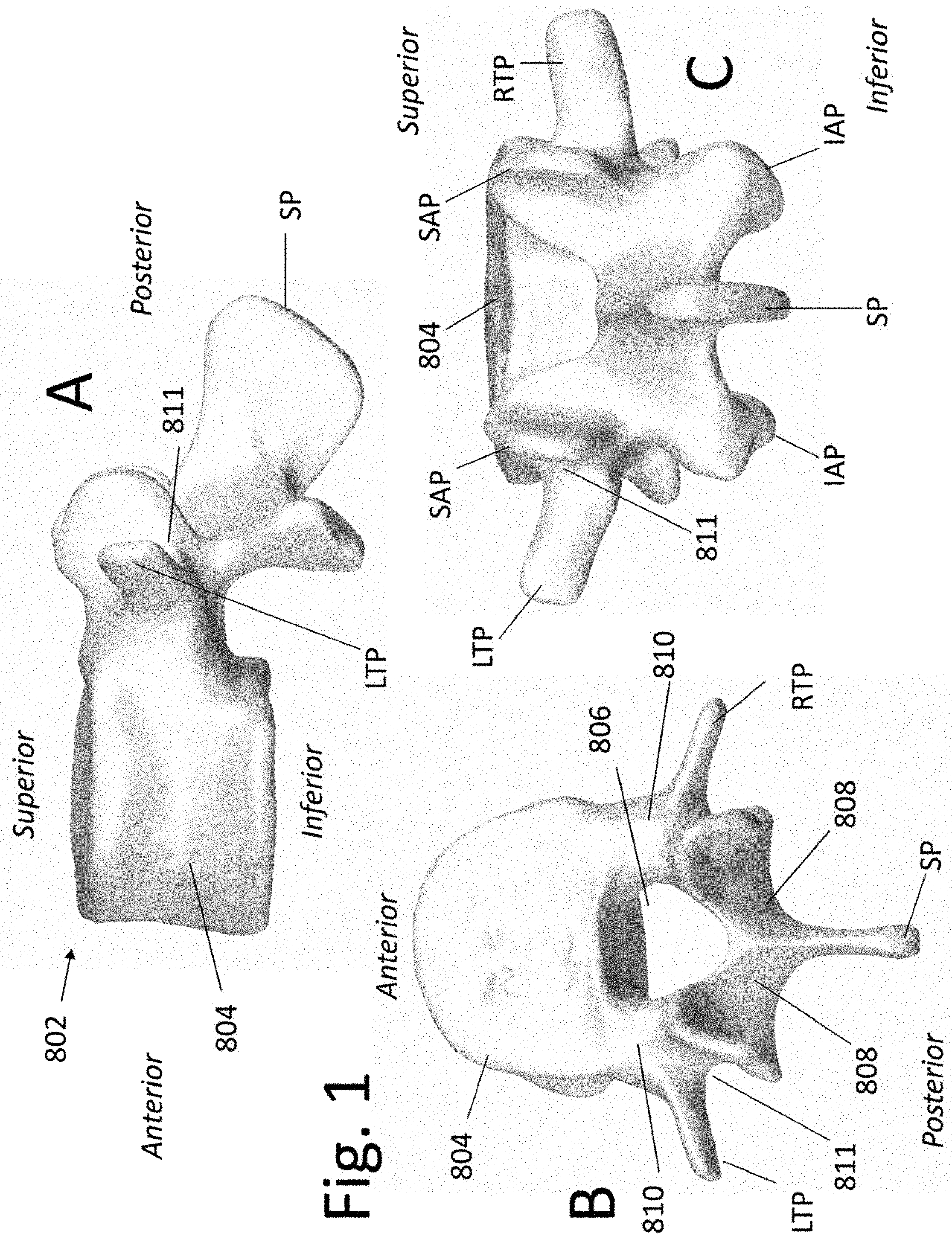
[0018] FIG. 1 are a schematic representations of a vertebral bone.
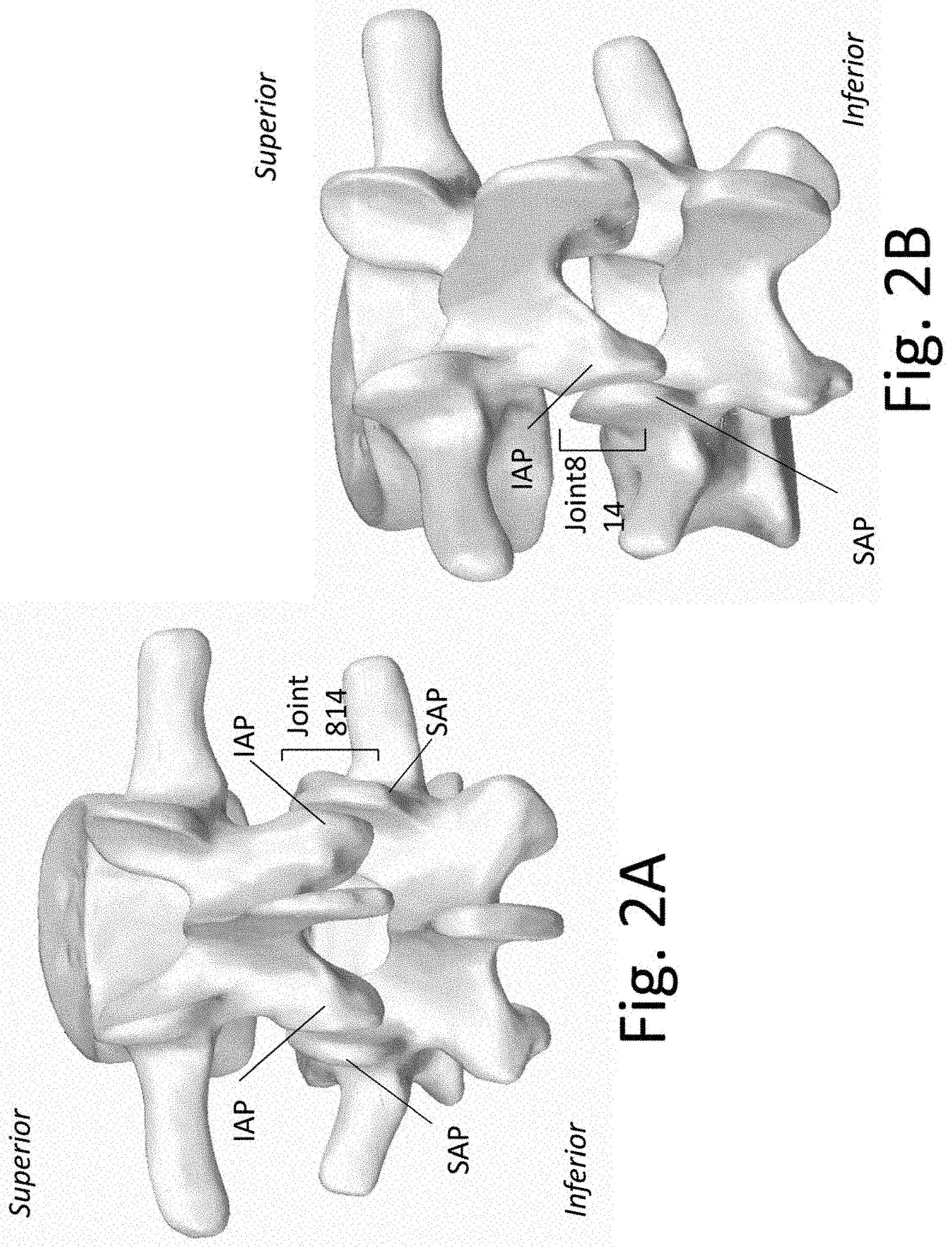
[0019] FIGS. 2A and 2B are a schematic representations of a Functional Spinal Unit (FSU) comprised of two adjunct vertebral bones and an intervening disc space.
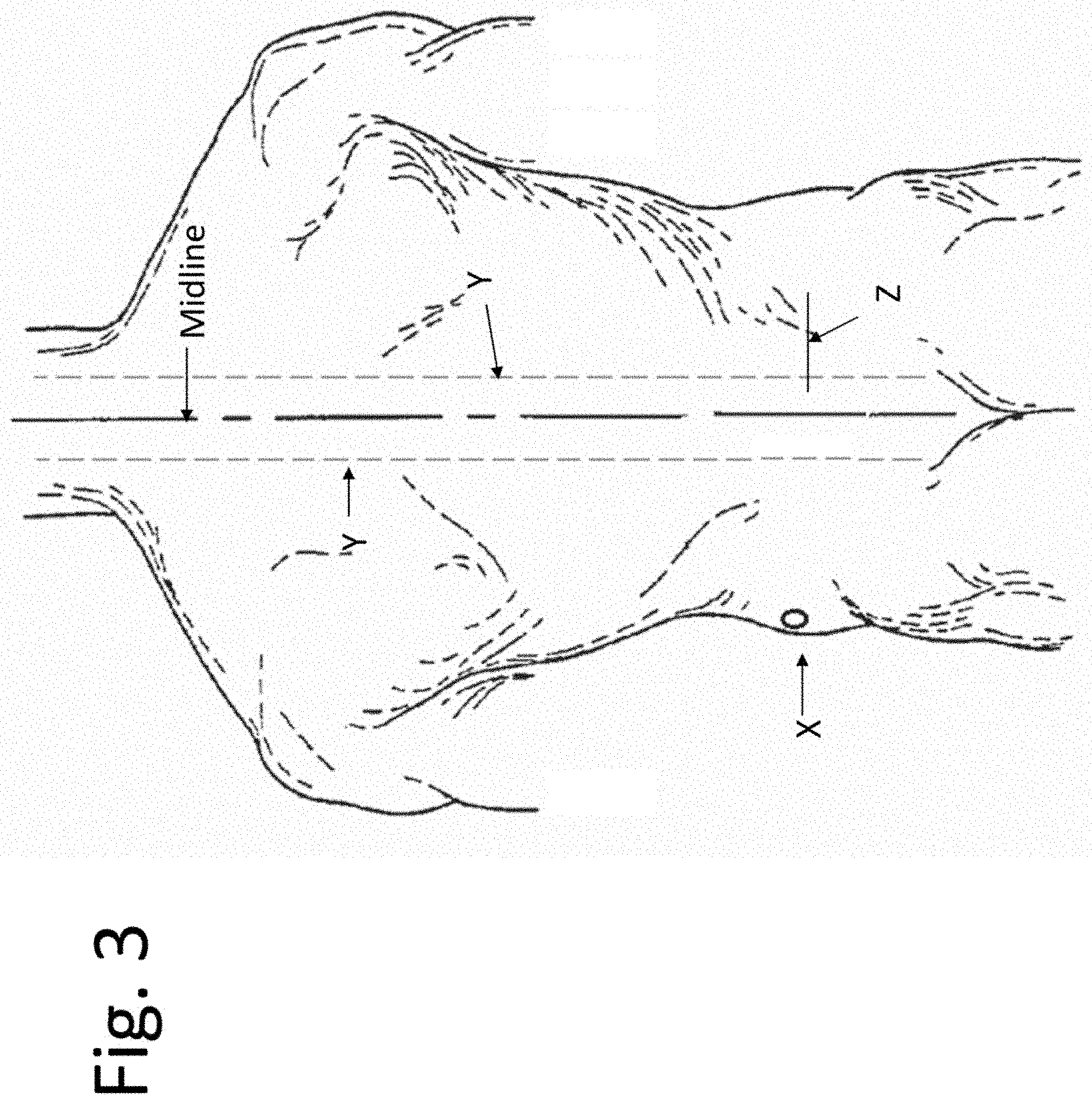
[0020] FIG. 3 illustrates the posterior aspect of a subject.
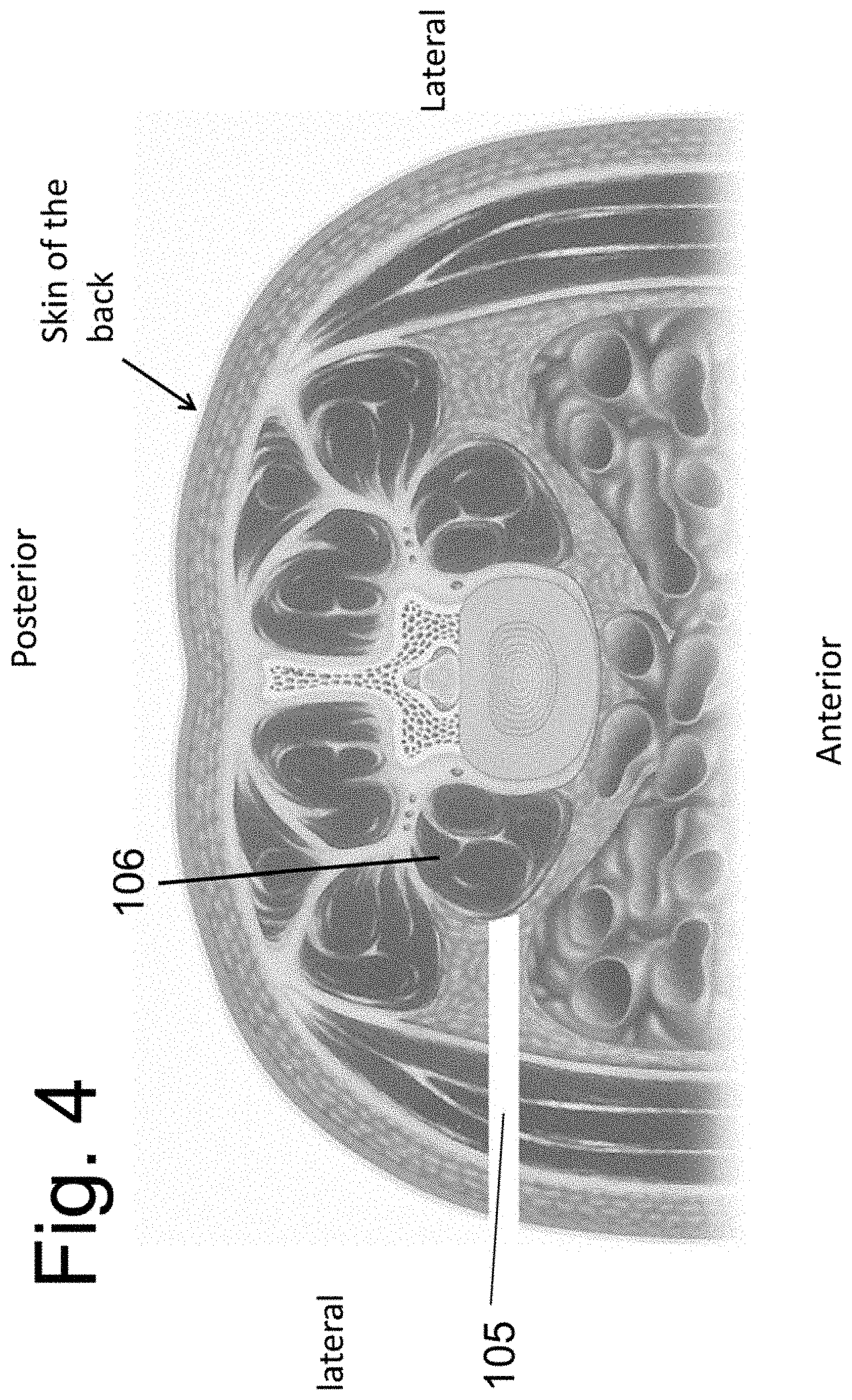
[0021] FIG. 4 is a schematic representation of a human torso in cross-section.
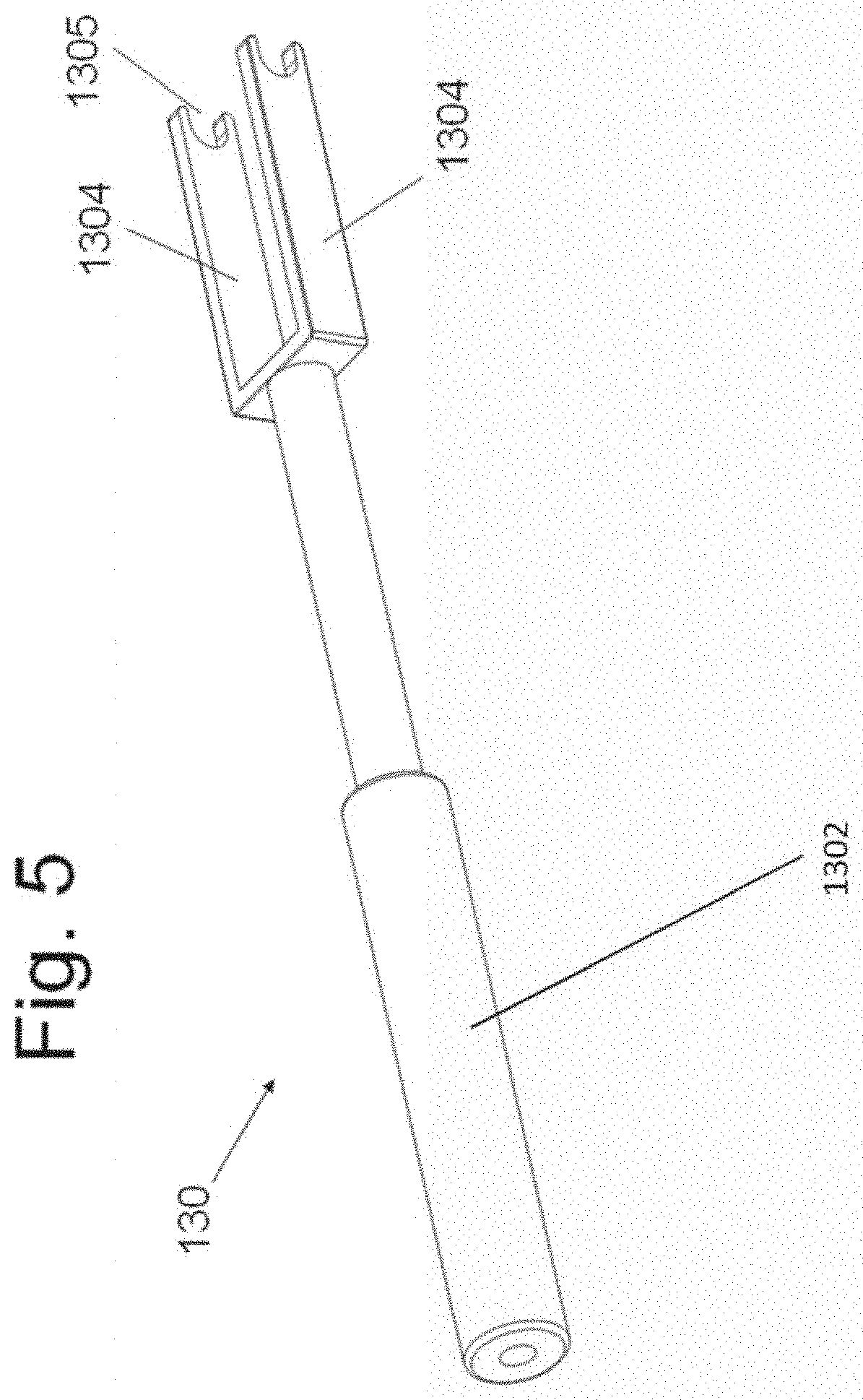
[0022] FIG. 5 illustrates an assembled embodiment of the present disclosure.
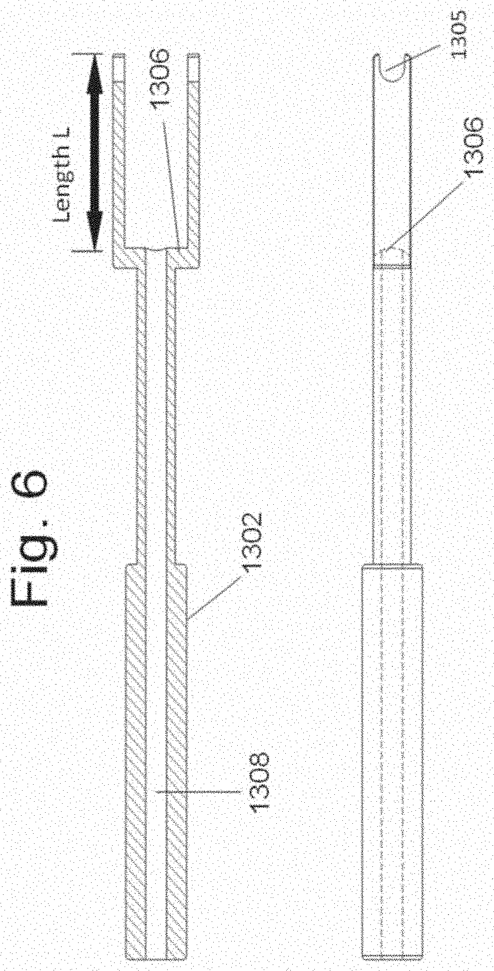
[0023] FIG. 6 illustrates section views of the disclosed instrument 130.
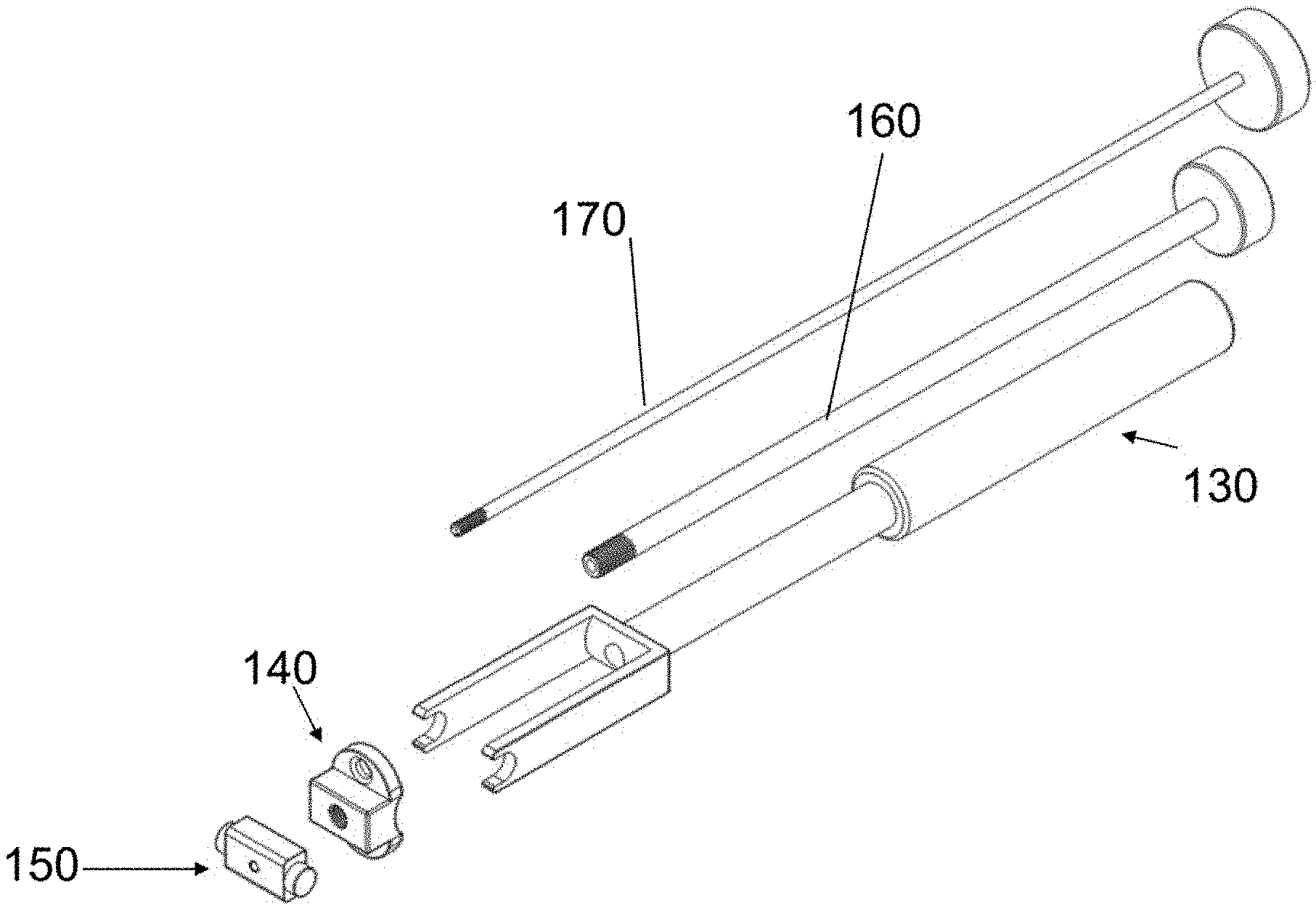
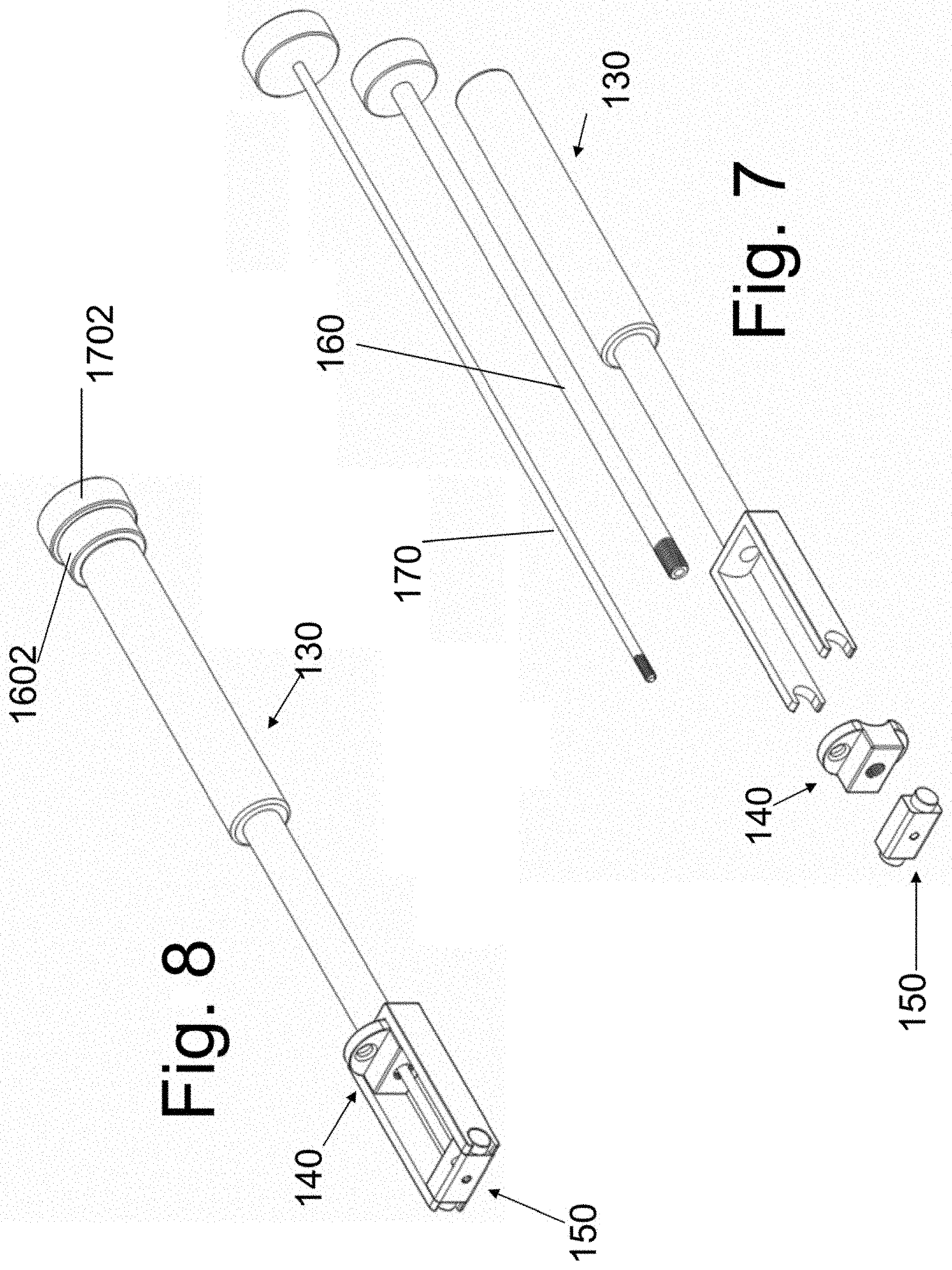
[0024] FIGS. 7 and 8 are exploded and assembled views of the placement instrument 130 and the attached spacers/implants.
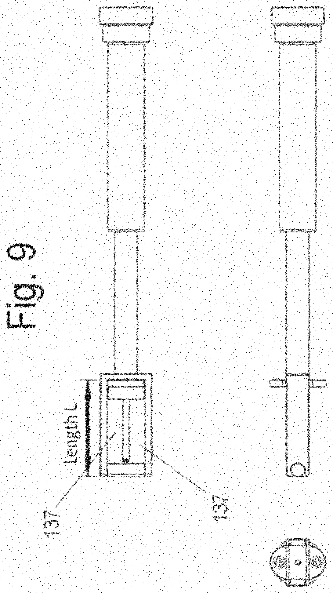
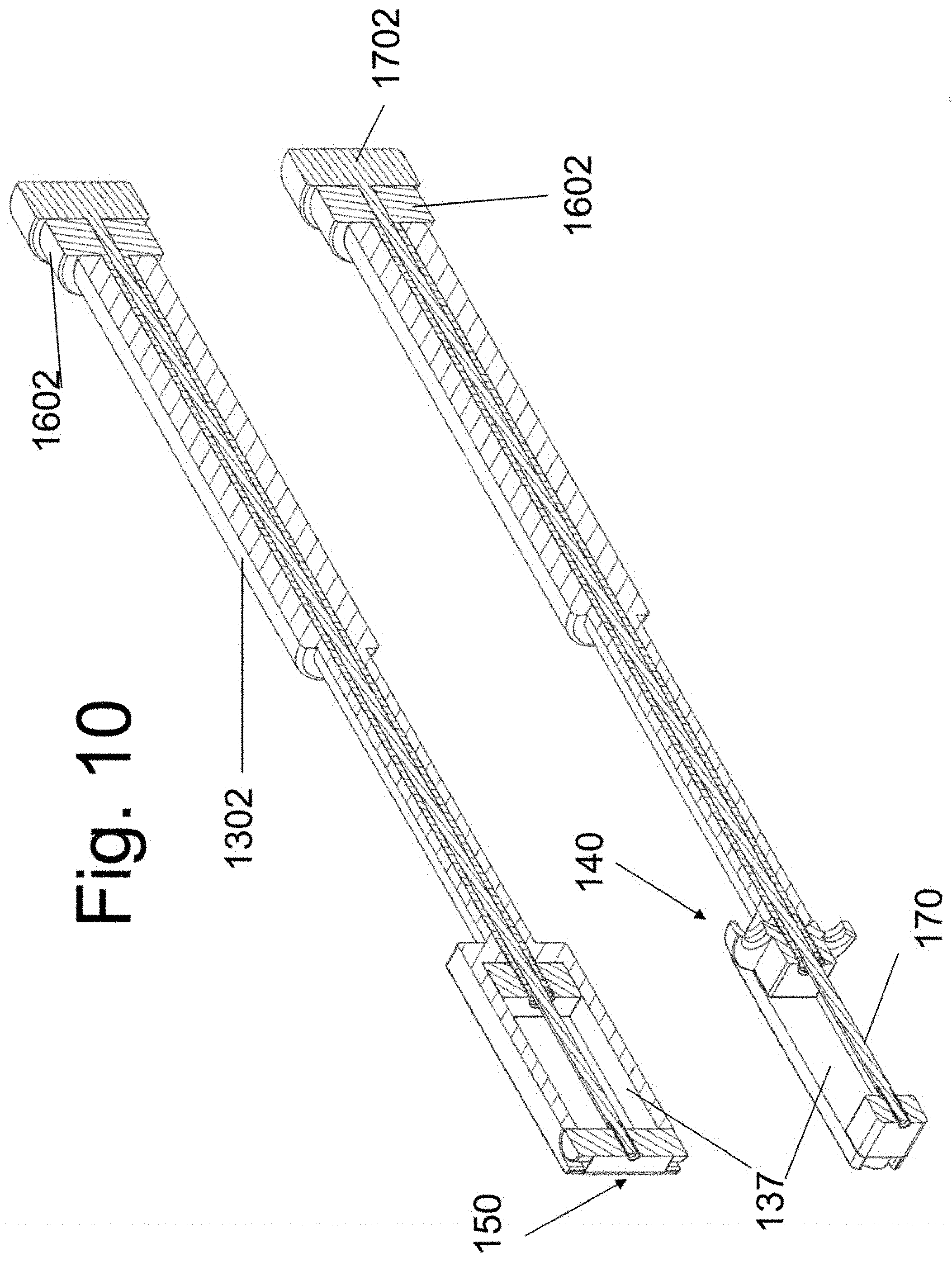
[0025] FIGS. 9 and 10 are perspective and orthogonal views of the device assembly.
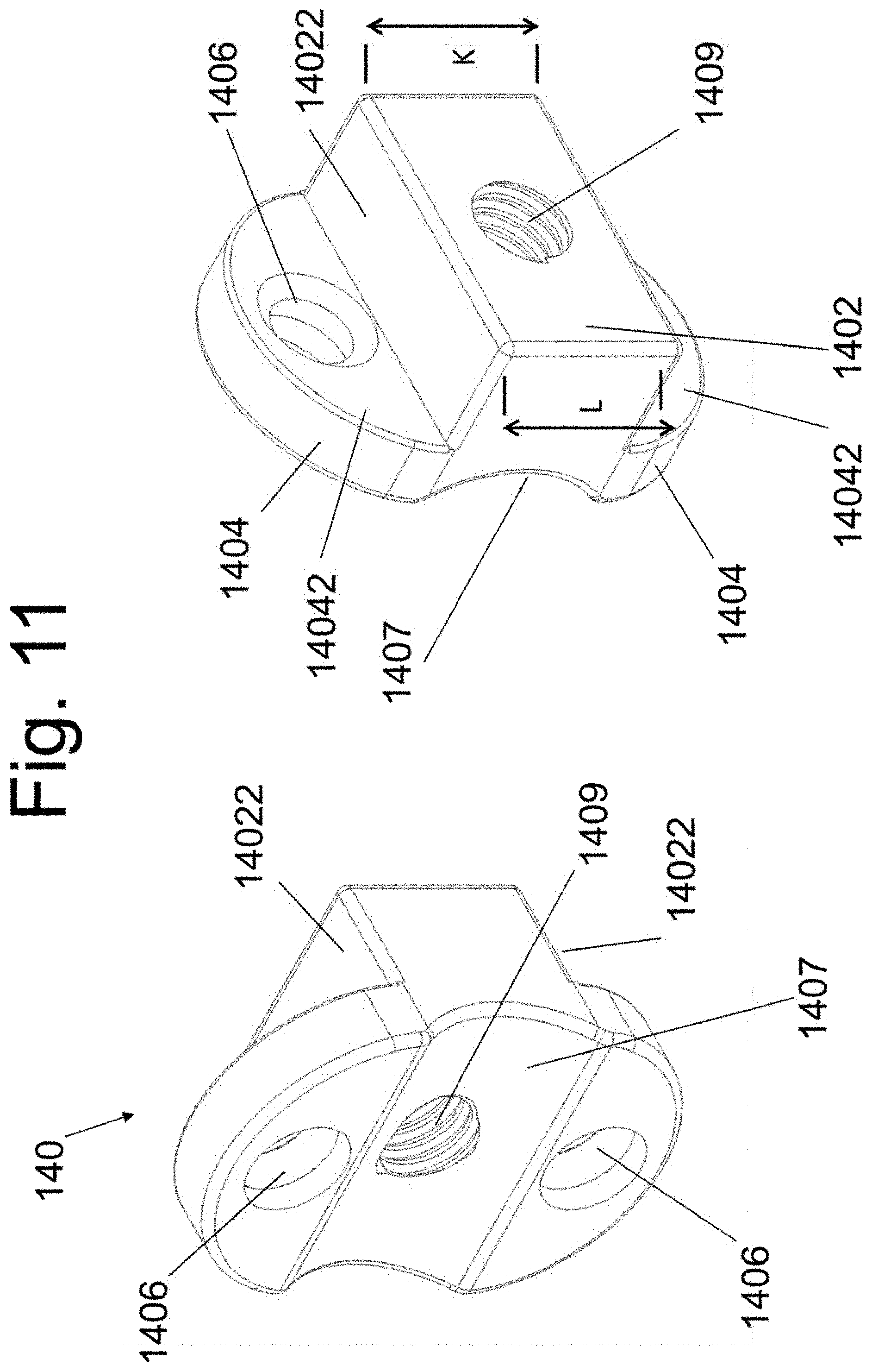
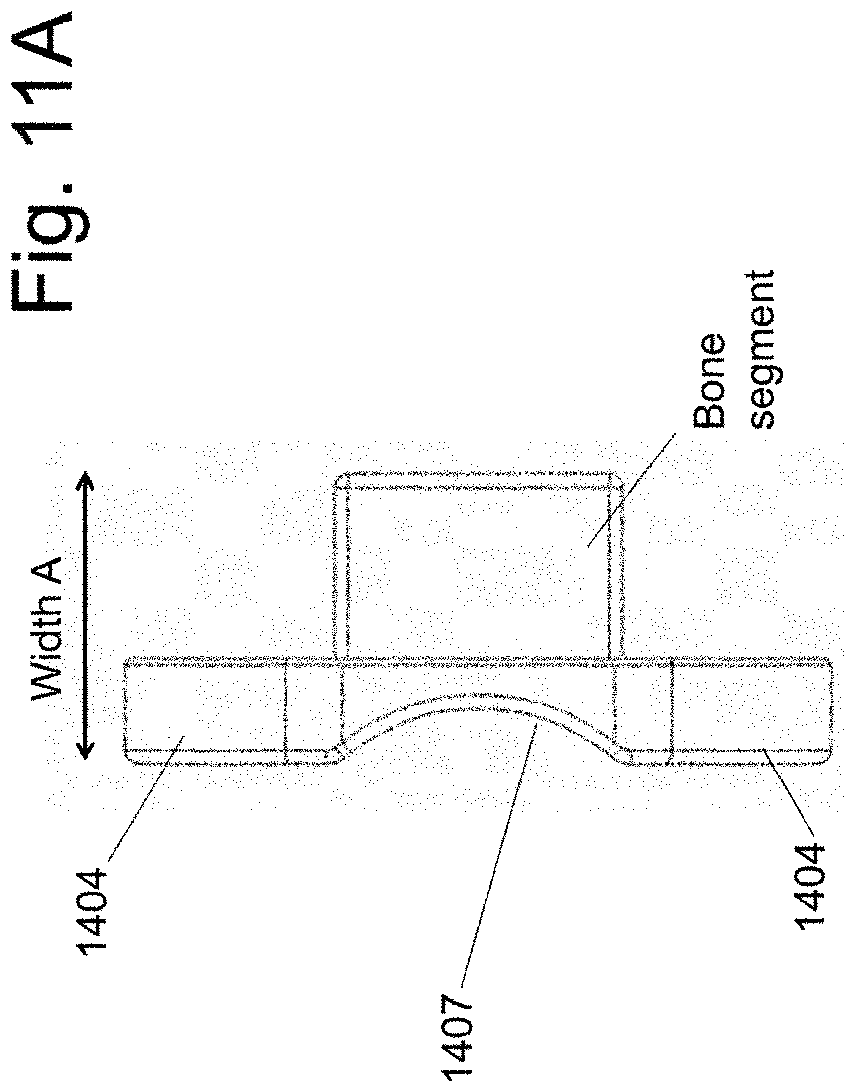
[0026] FIGS. 11 and 11A illustrate the implantable spacers of the present disclosure.
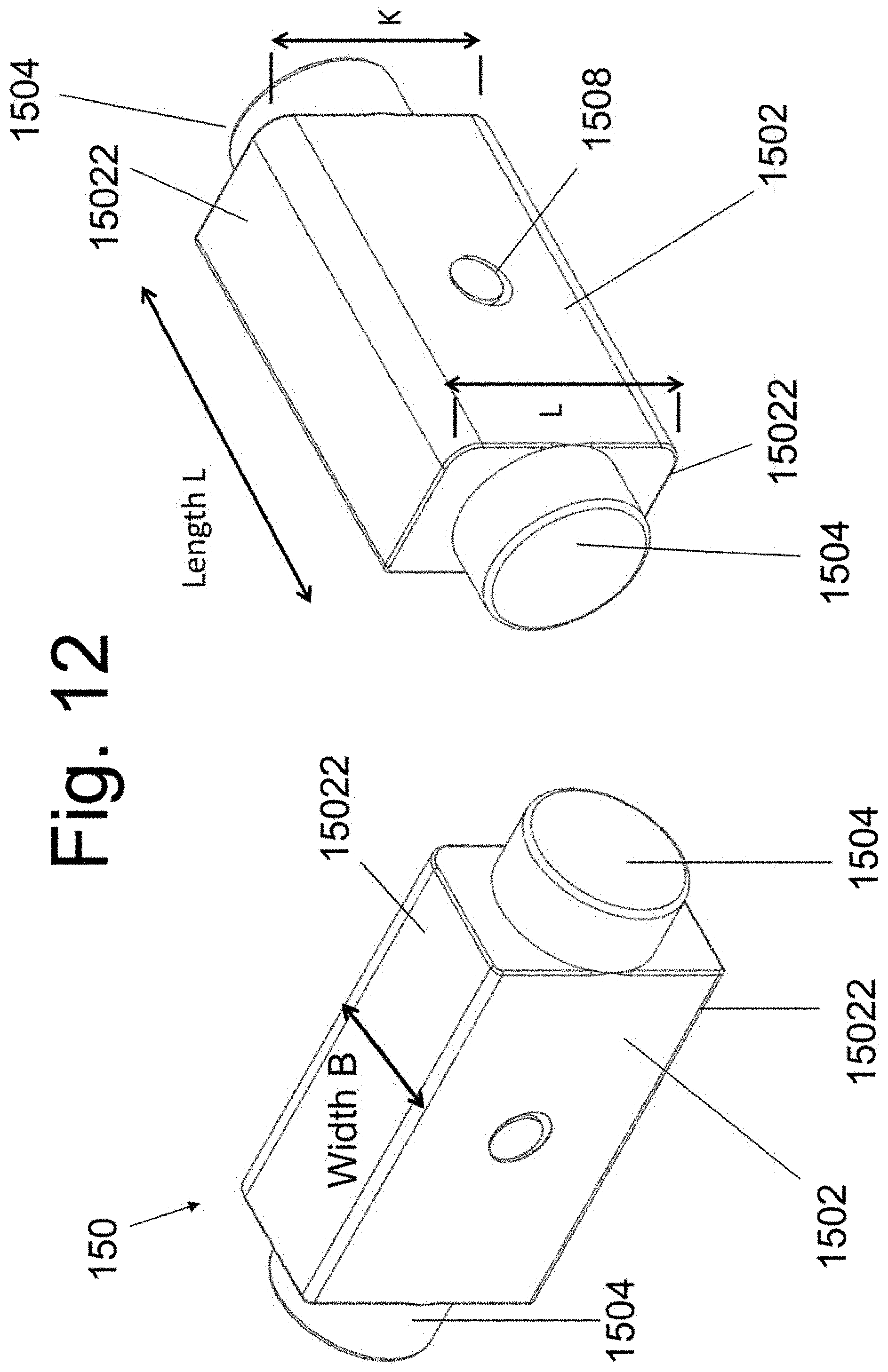
[0027] FIG. 12 illustrates views of the implantable spacer 150.
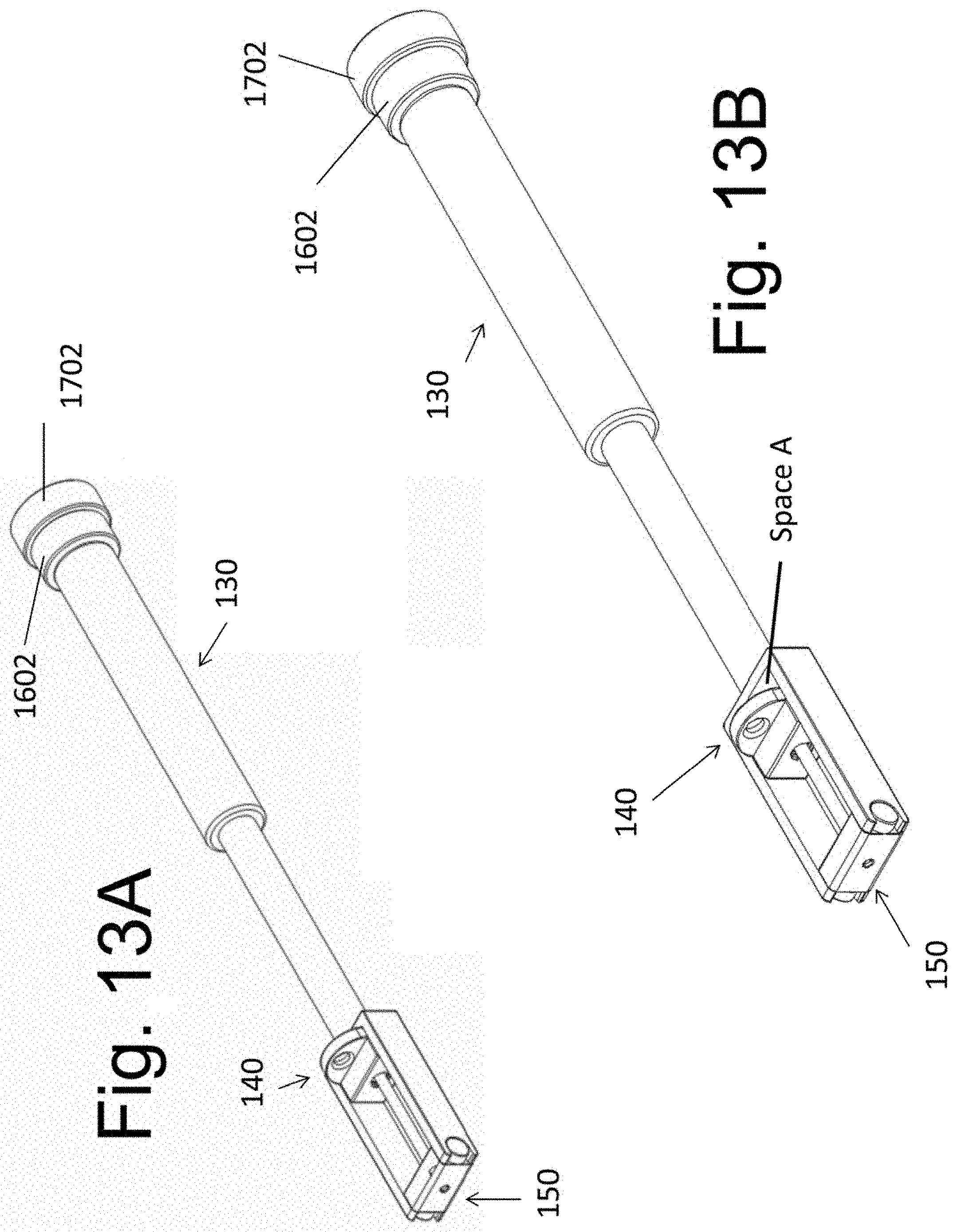
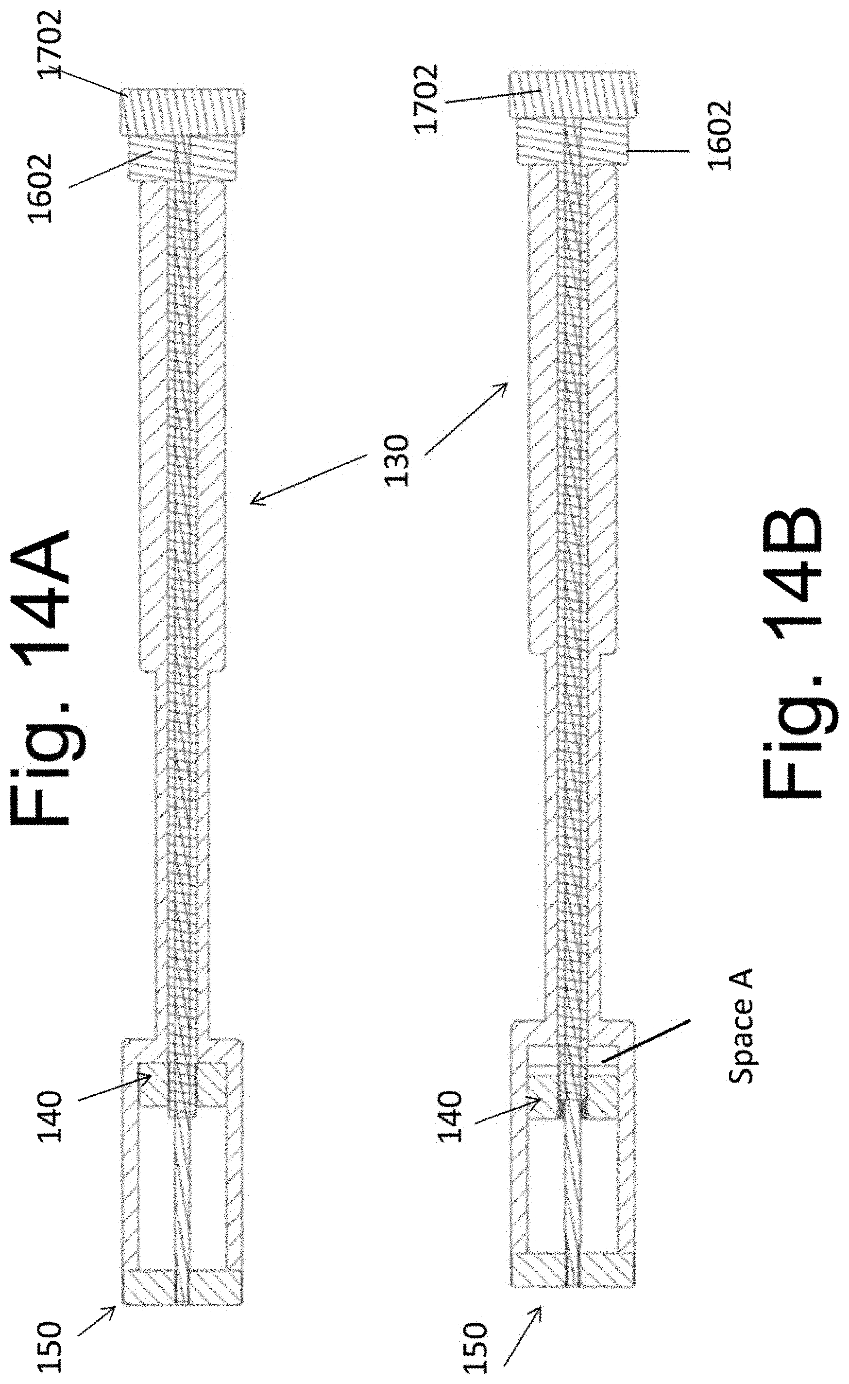
[0028] FIGS. 13A, 13B, 14A, and 14B illustrate an exemplary instrument 130 configured to retain implantable spacers 140 at a variable distance relative to the spacer 150.
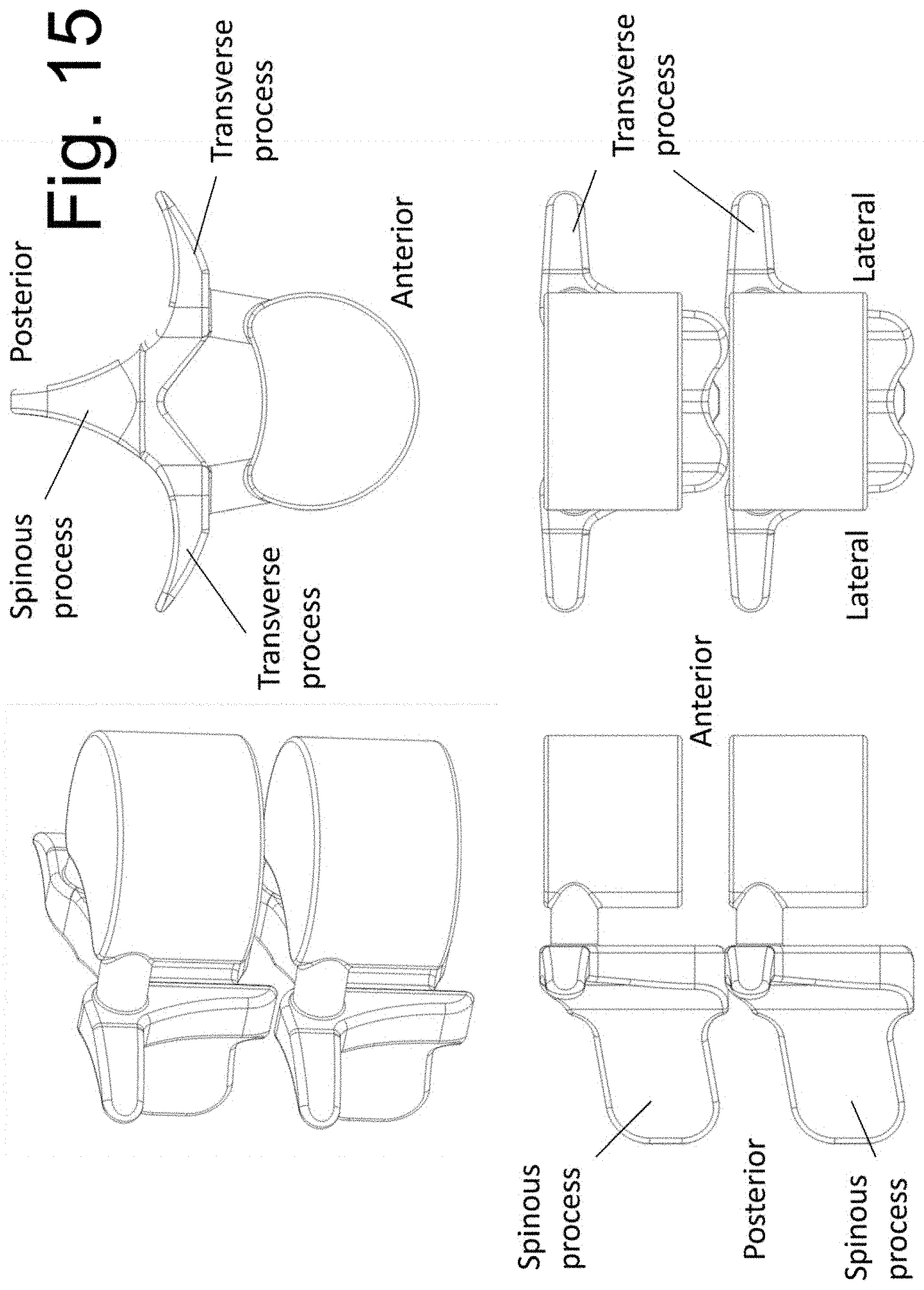
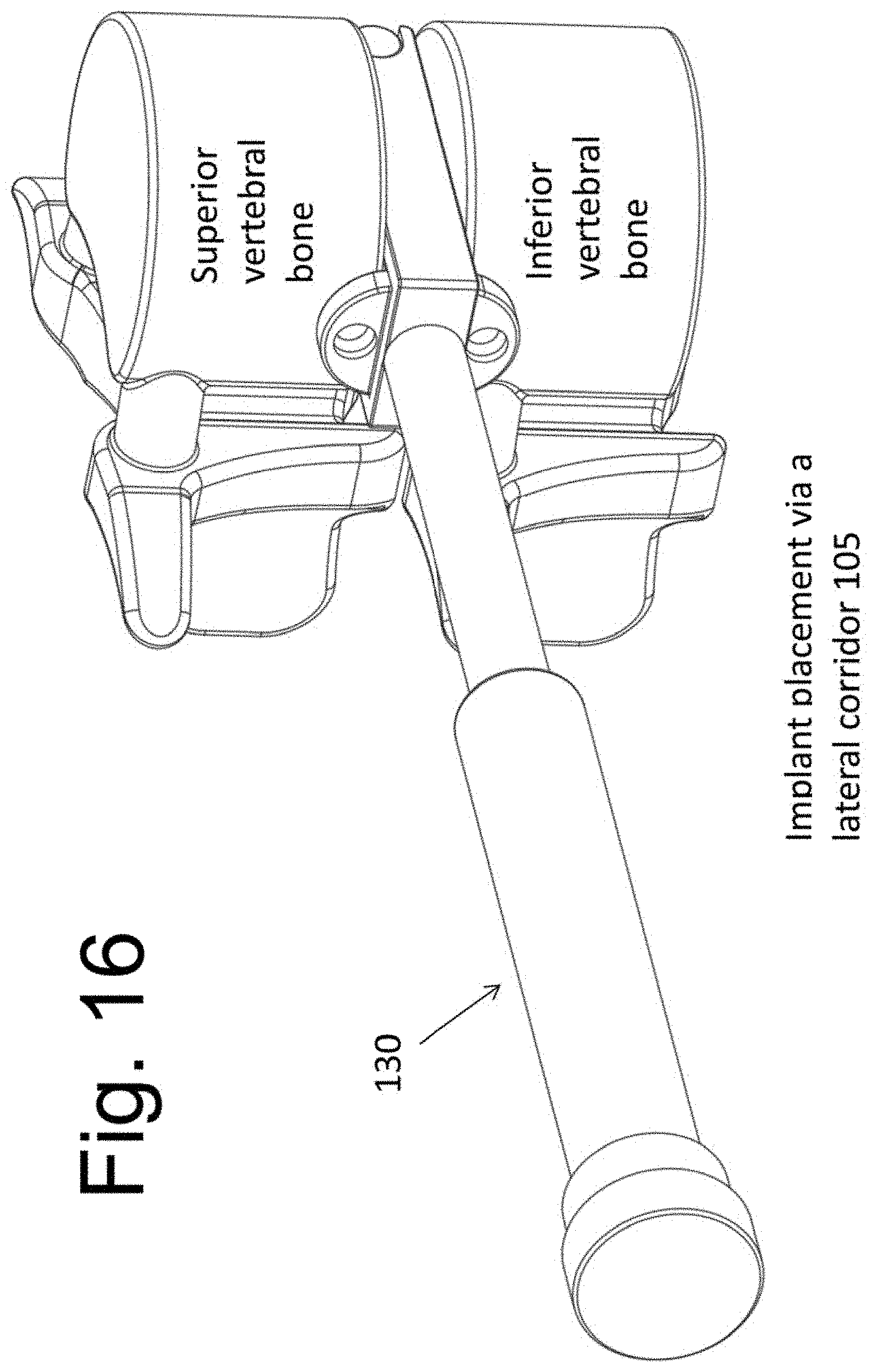
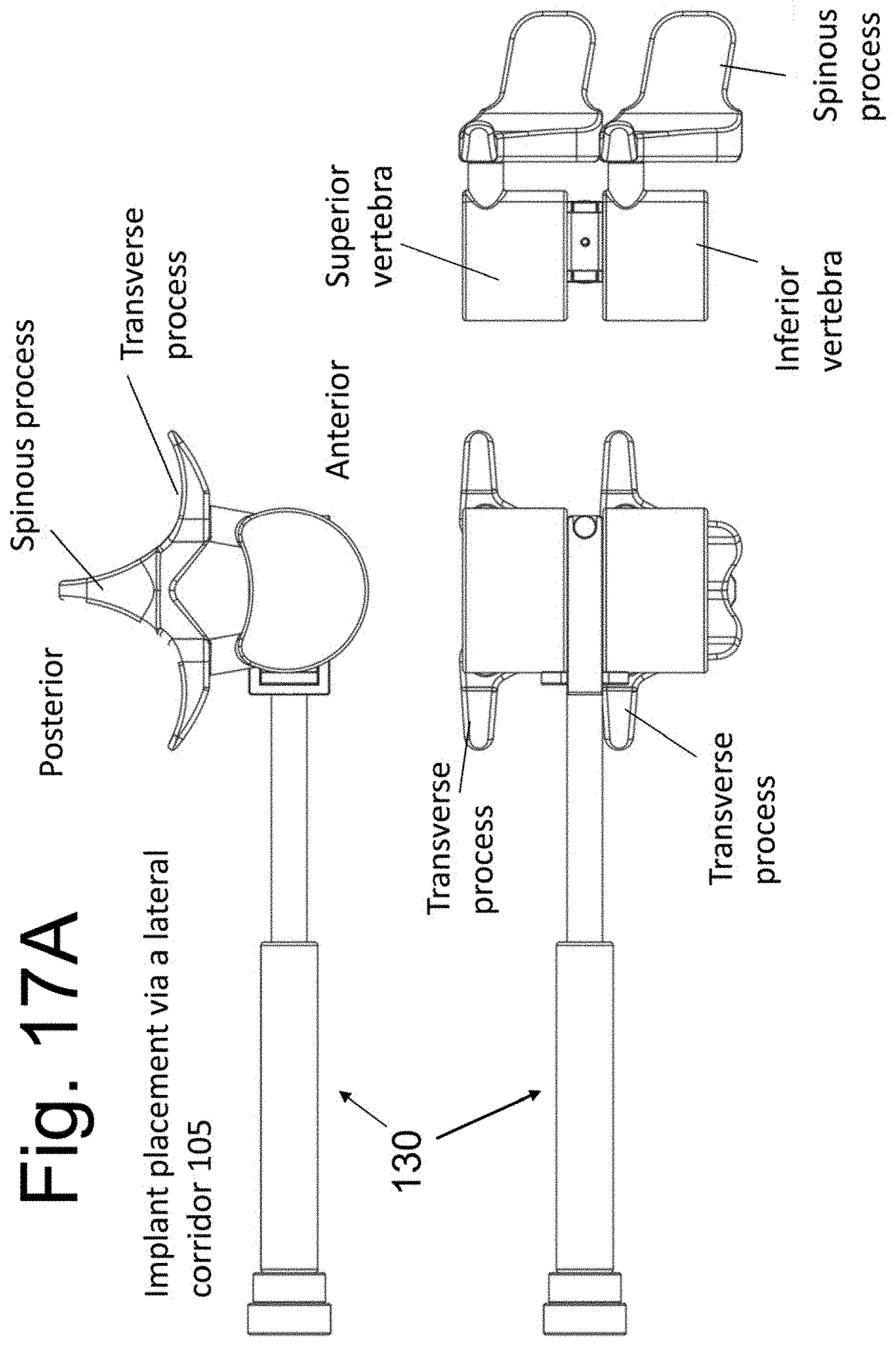
[0029] FIGS. 15, 16, and 17A show a Functional Spinal Unit (FSU) before and after implantation.
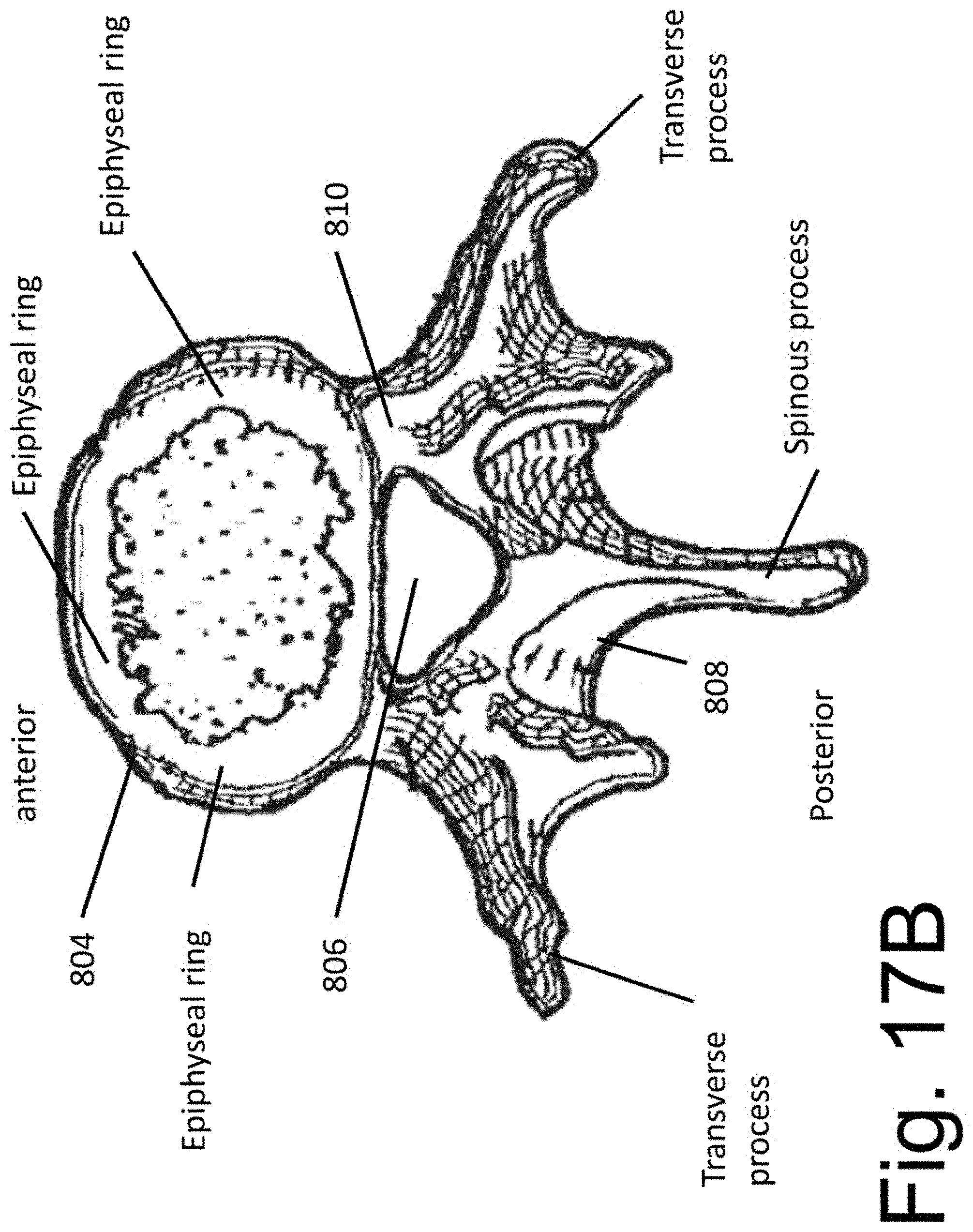
[0030] FIG. 17B illustrates a top surface of a vertebral bone and the epiphyseal ring.
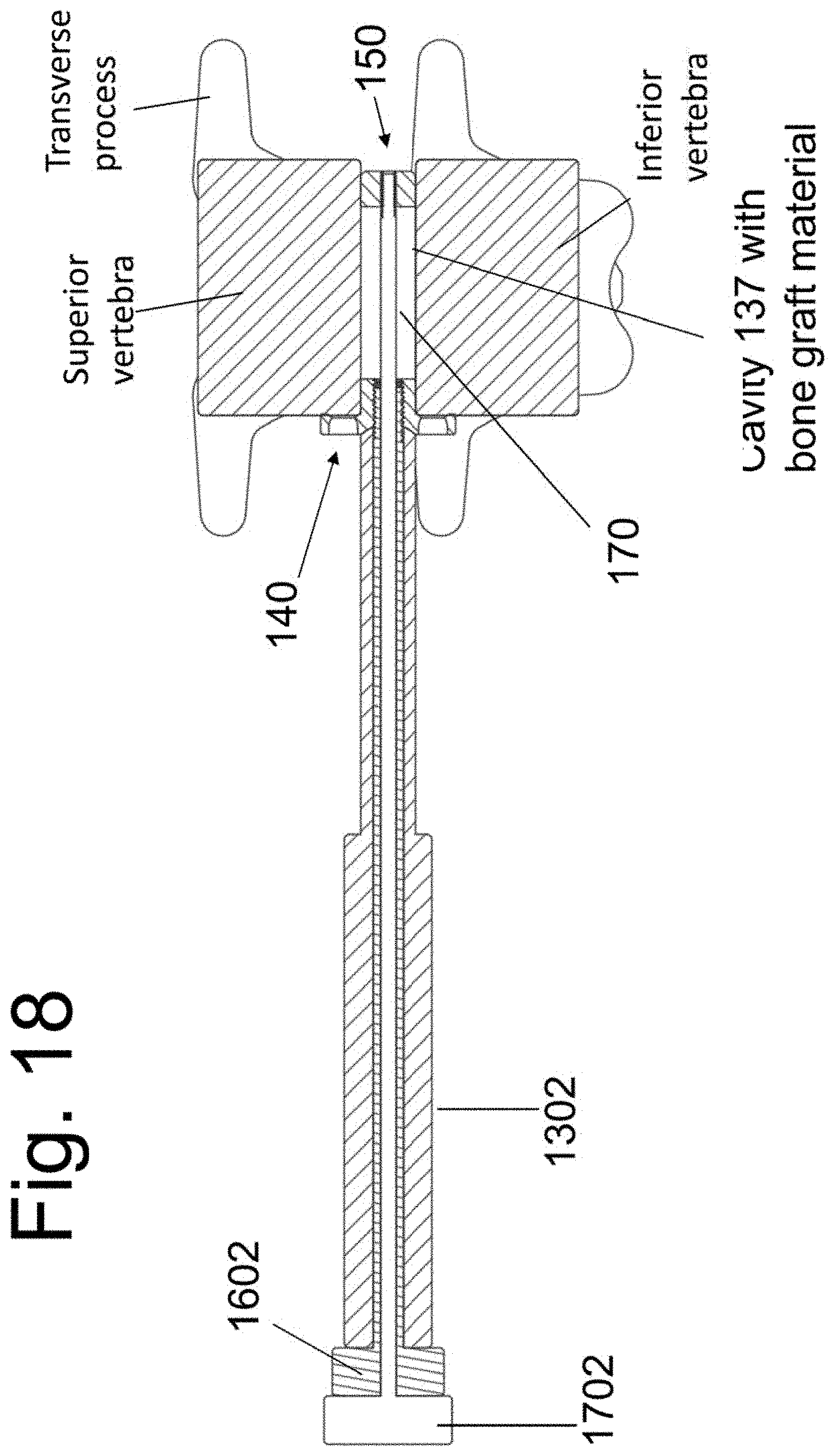
[0031] FIG. 18 is a cross sectional view of the implanted FSU with the instrument 130 in place.
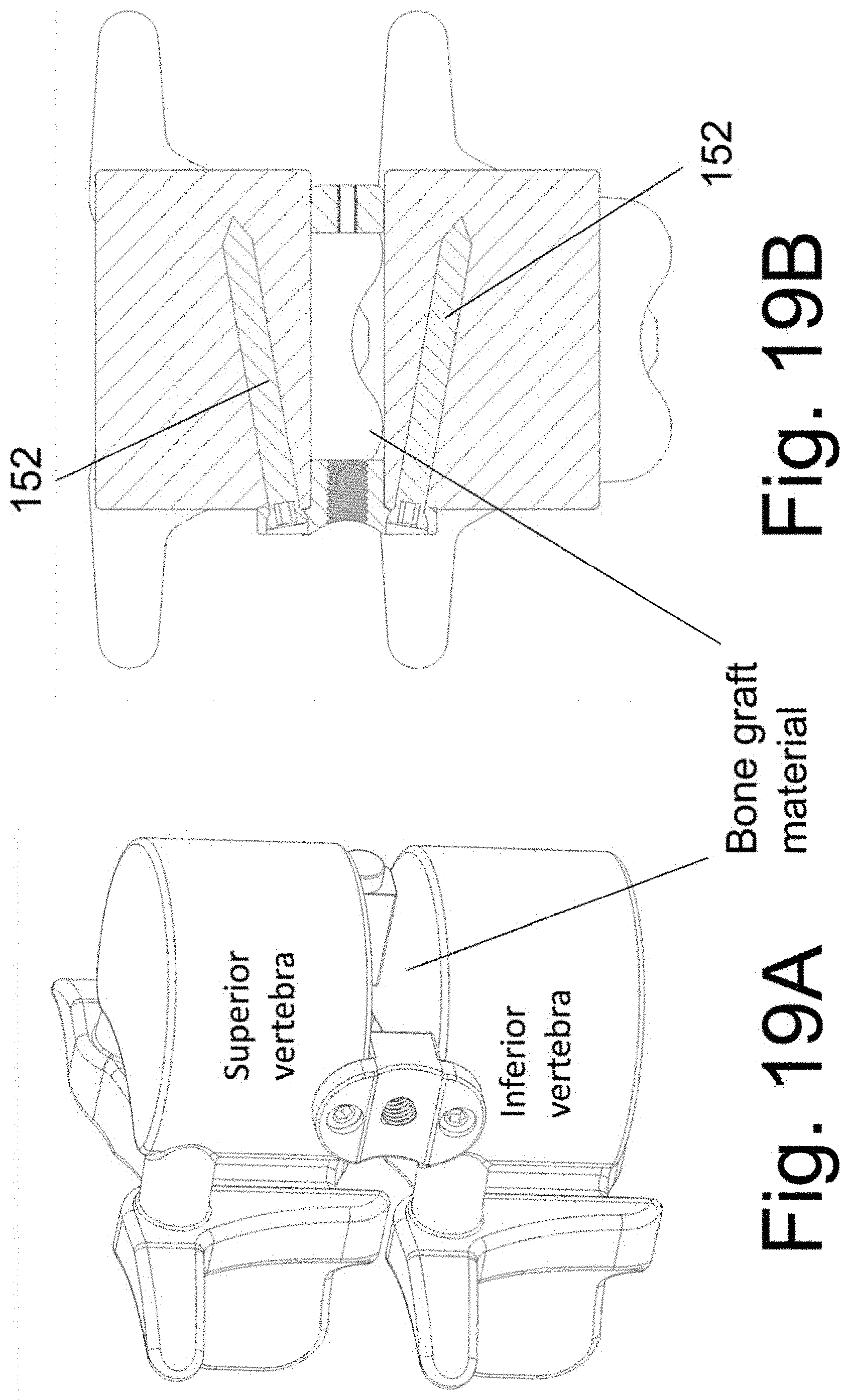
[0032] FIGS. 19A and 19B illustrate the implantable spacers 140 and 150 after removal of the instrument 130.
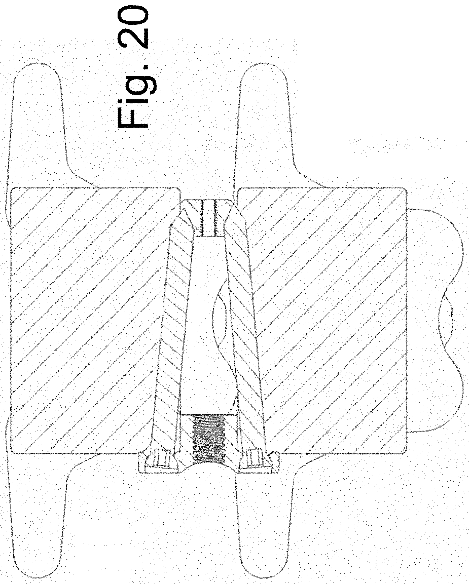
[0033] FIG. 20 illustrates an alternative screw trajectory in the placement of a larger tissue dilator over the tissue dilator of FIG. 19B.
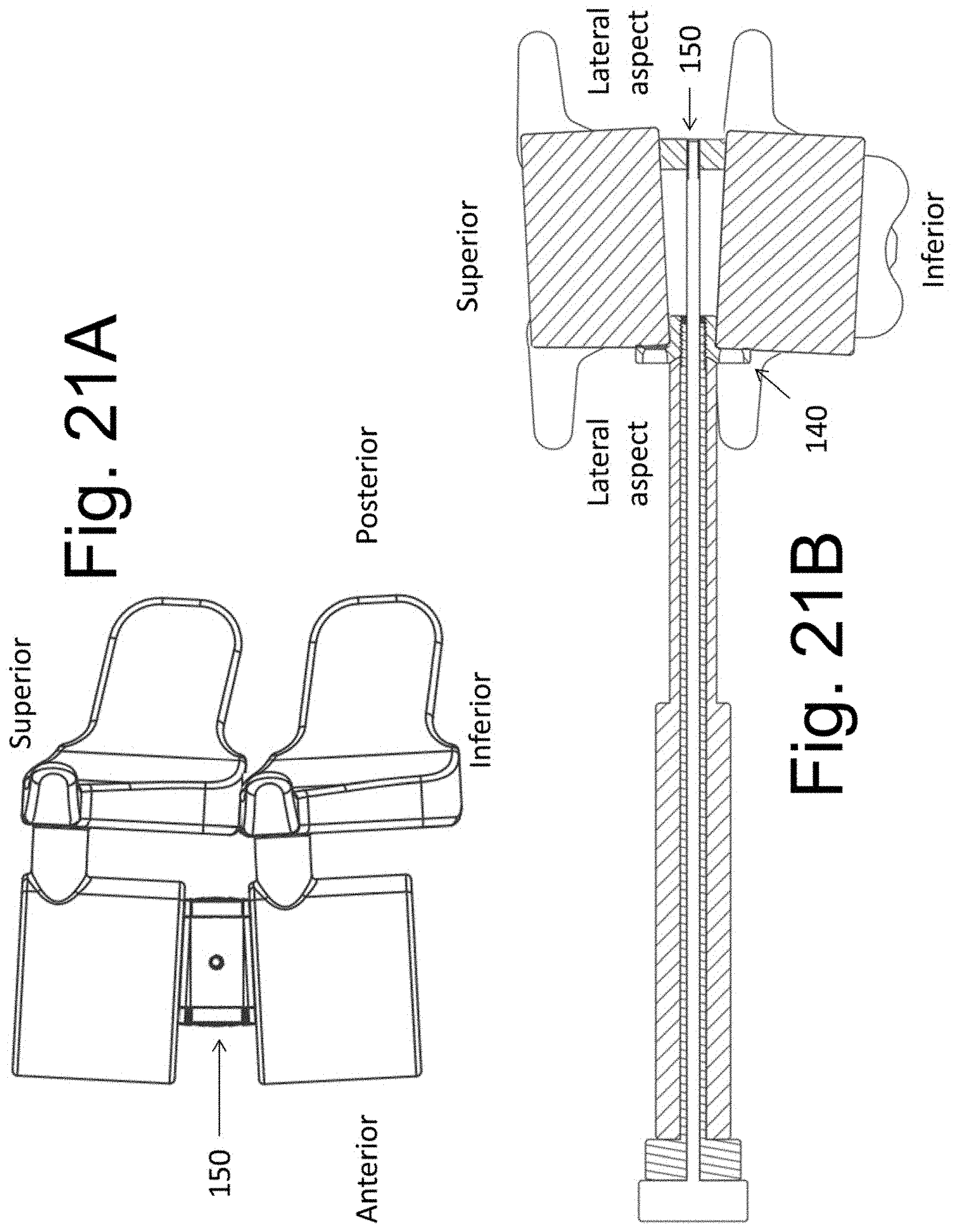
[0034] FIGS. 21A and 21B illustrate a change in vertebral alignment in the coronal and/or sagittal planes from placement of implantable spacers of varying sizes.
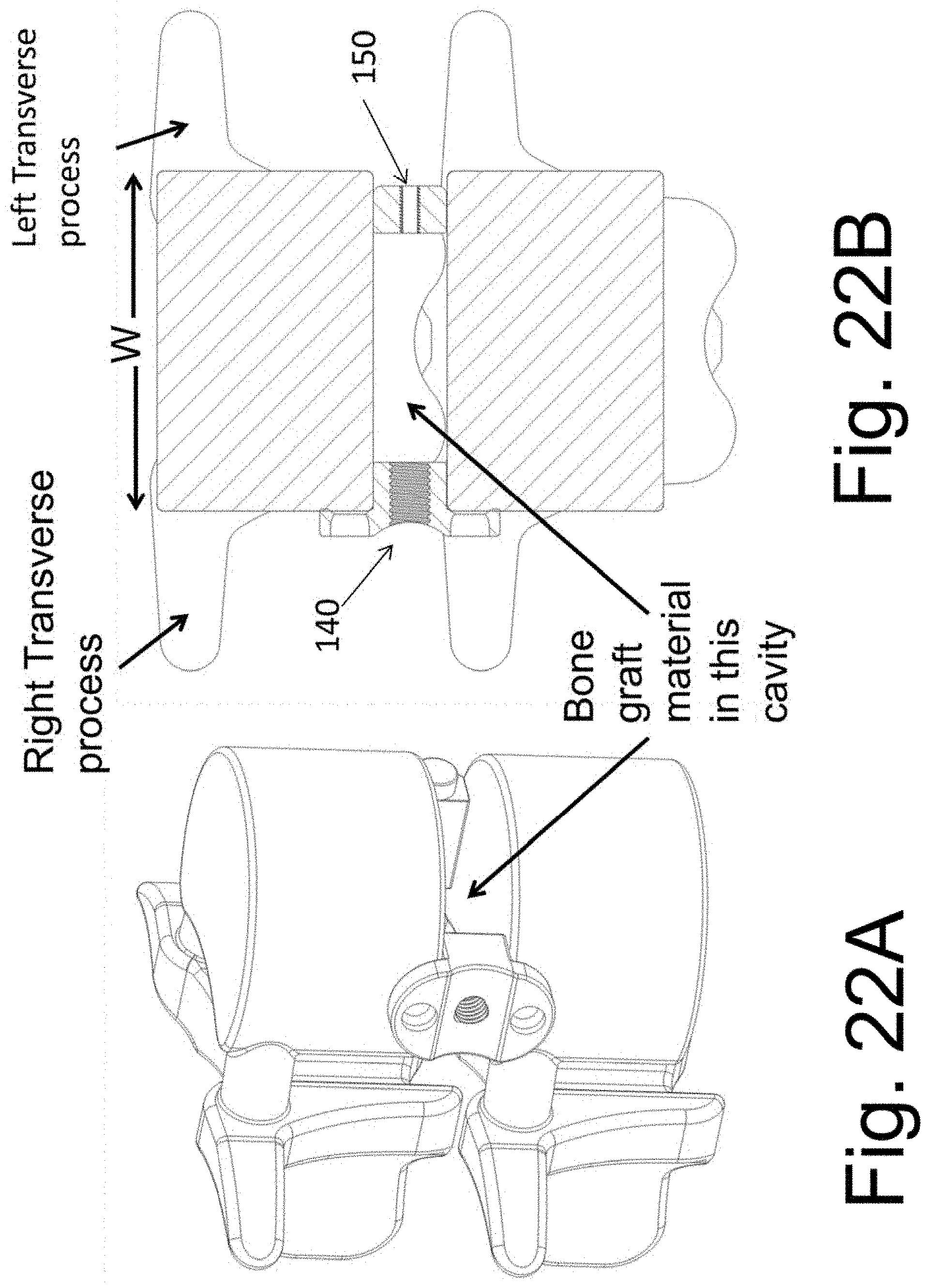
[0035] FIGS. 22A and 22B illustrate the implantable spacers 140 and 150 after removal of the disclosed instrument 130.
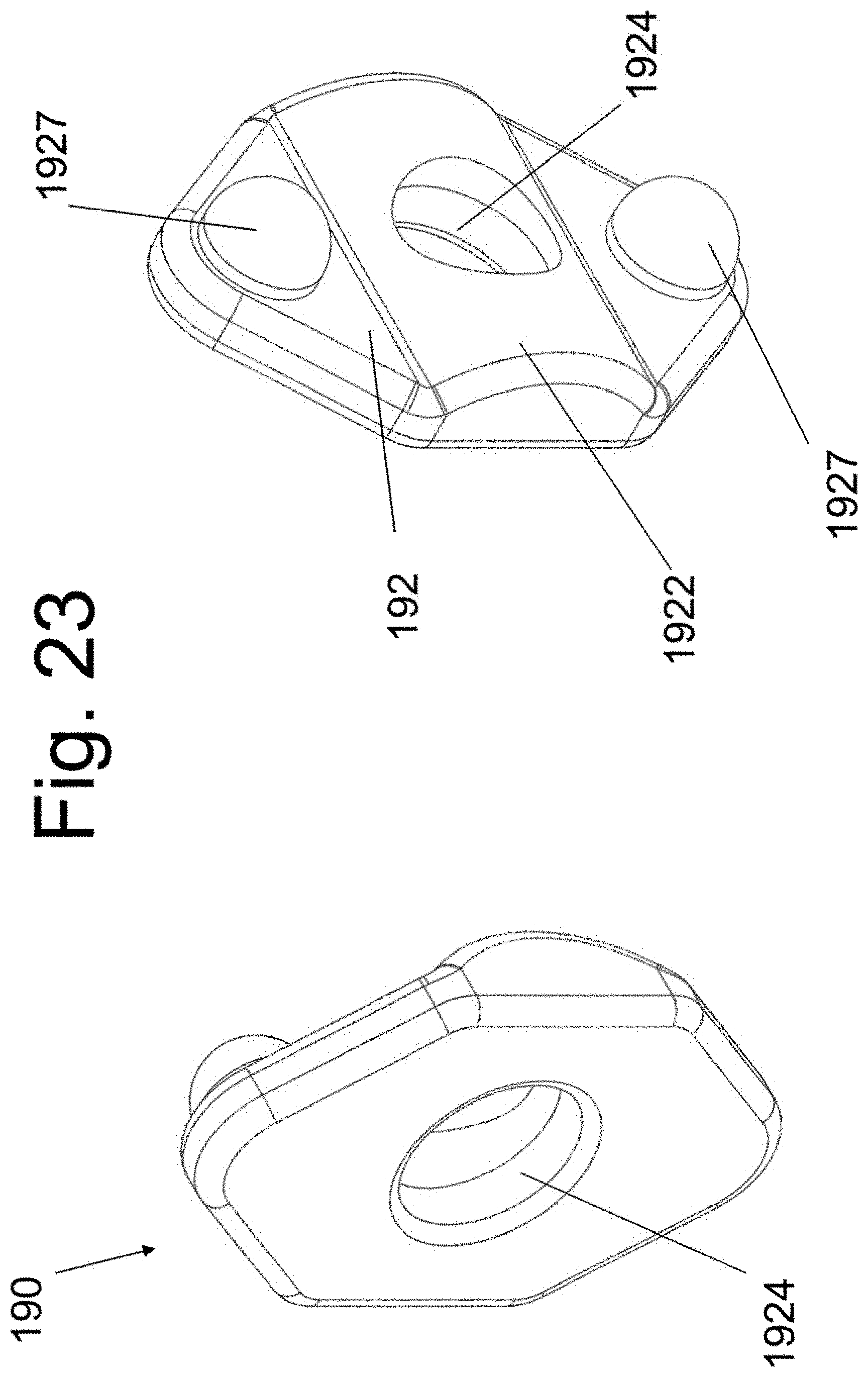
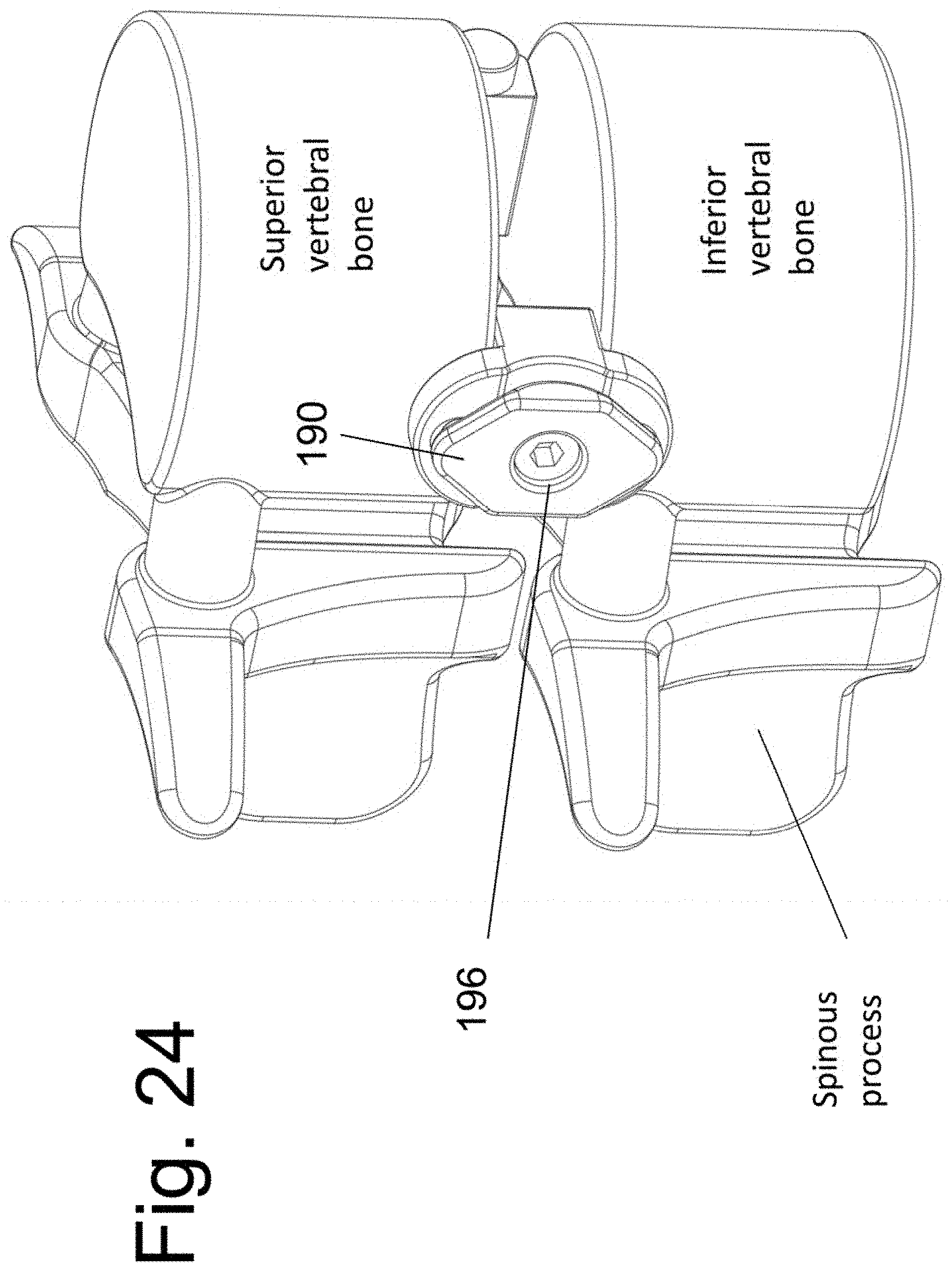
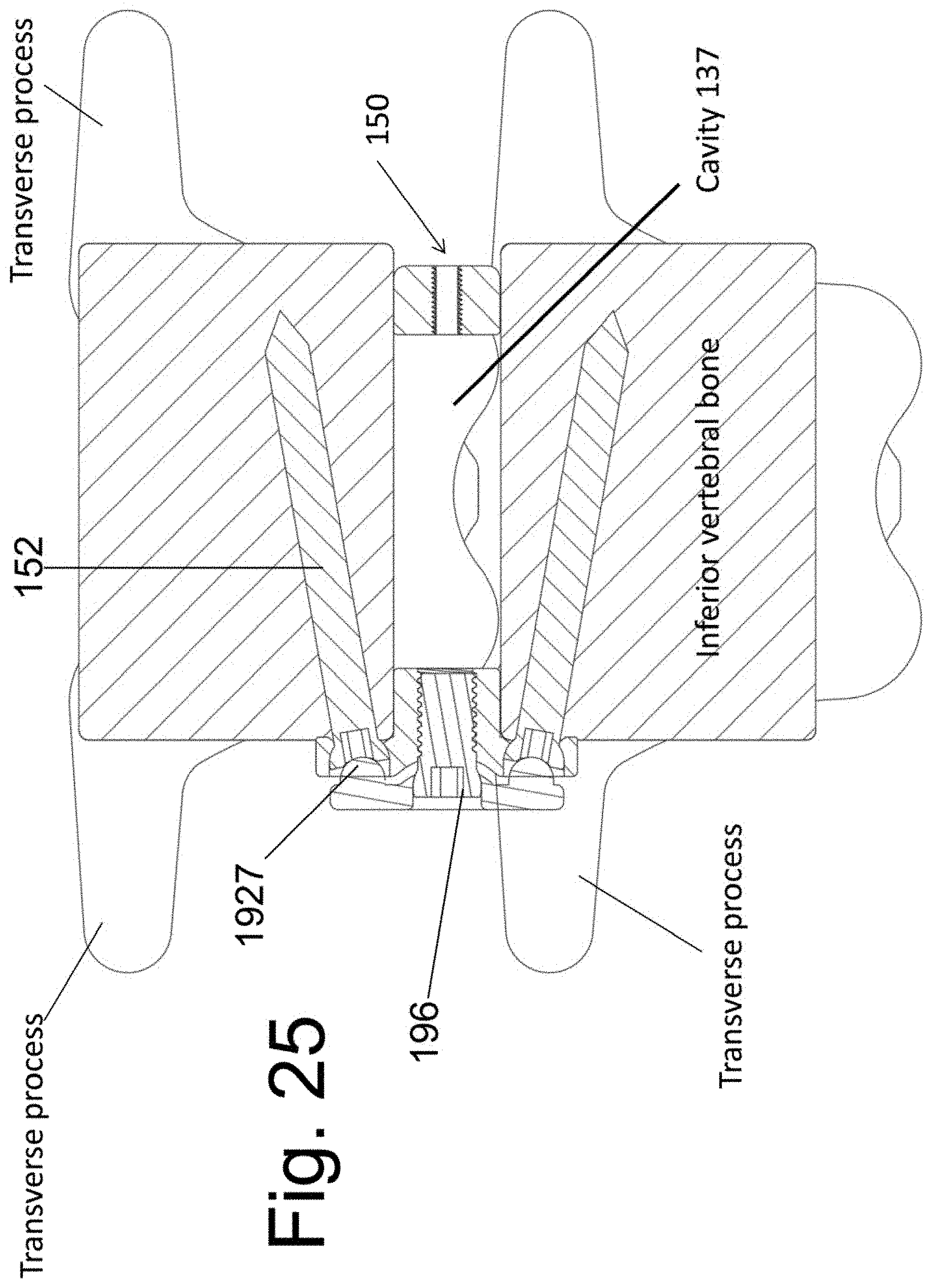
[0036] FIGS. 23, 24 and 25 illustrate the screw locking member 190 in perspective views and after attachment to the implantable spacer 140.
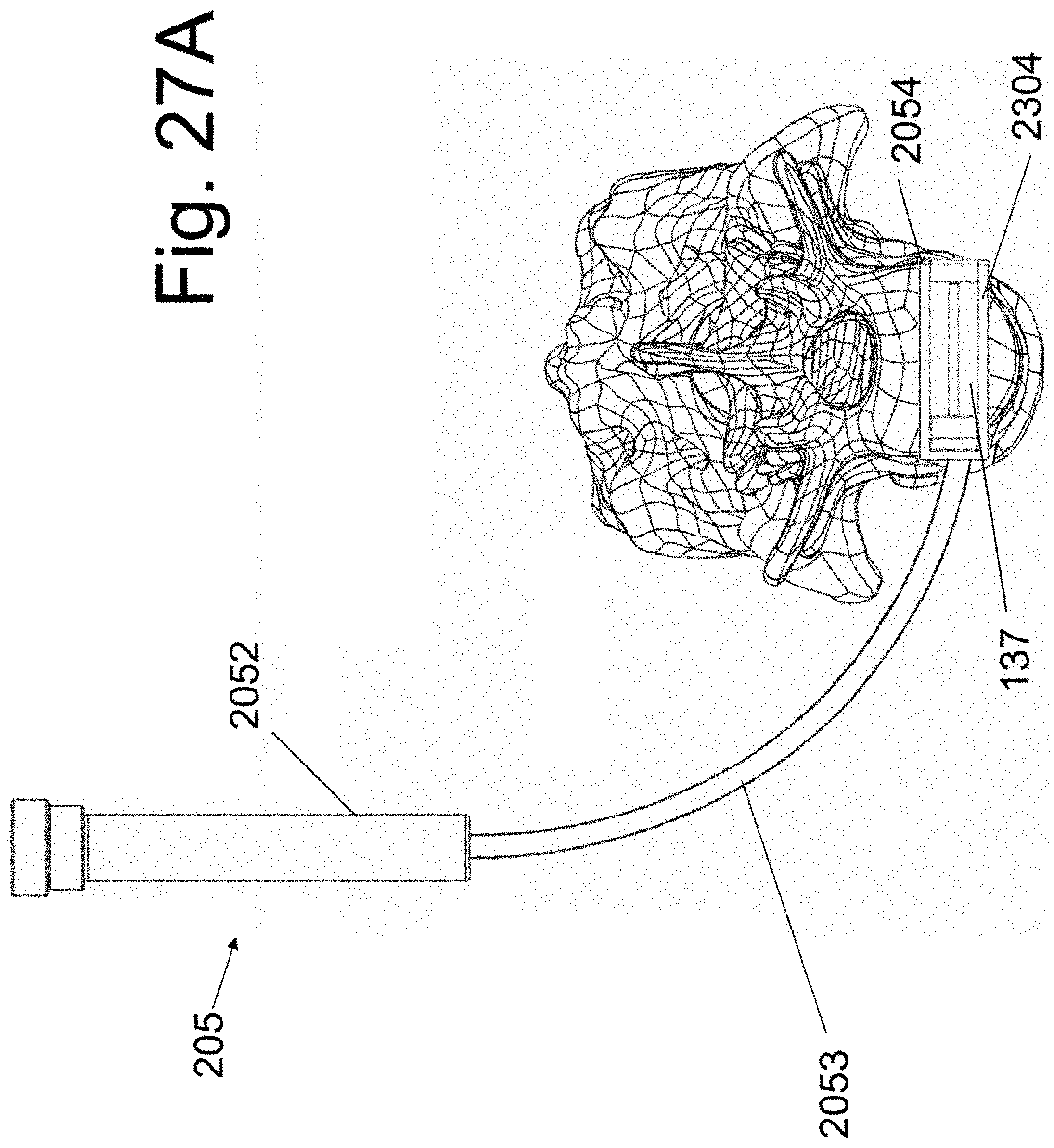
[0037] FIGS. 26 and 27A illustrate the use of a curvilinear embodiment of the present disclosure.
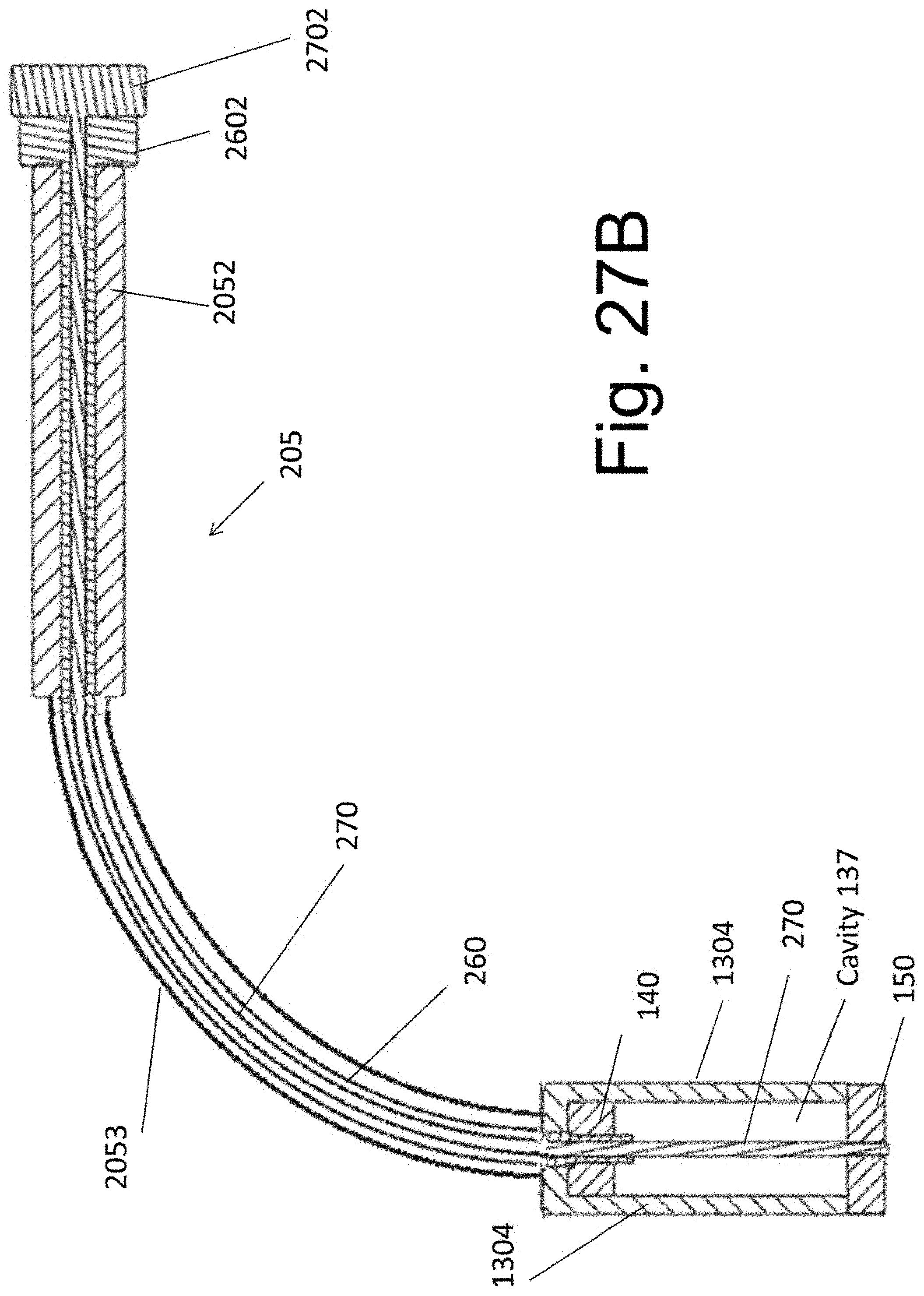
[0038] FIG. 27B illustrates a cross section view of the curvilinear embodiment.
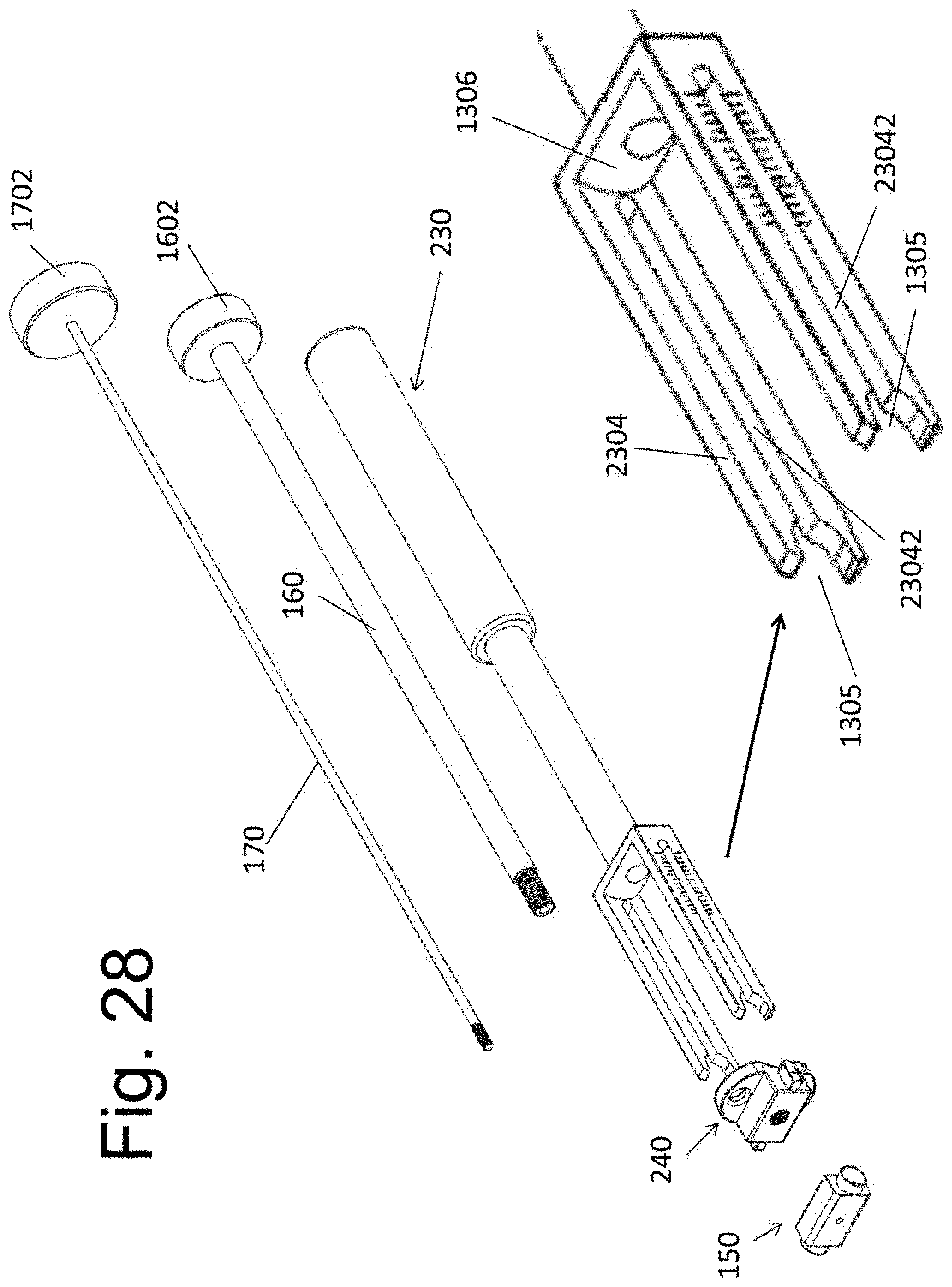
[0039] FIG. 28 illustrates an exploded view of an alternative device embodiment, wherein a placement instrument 230 is used.
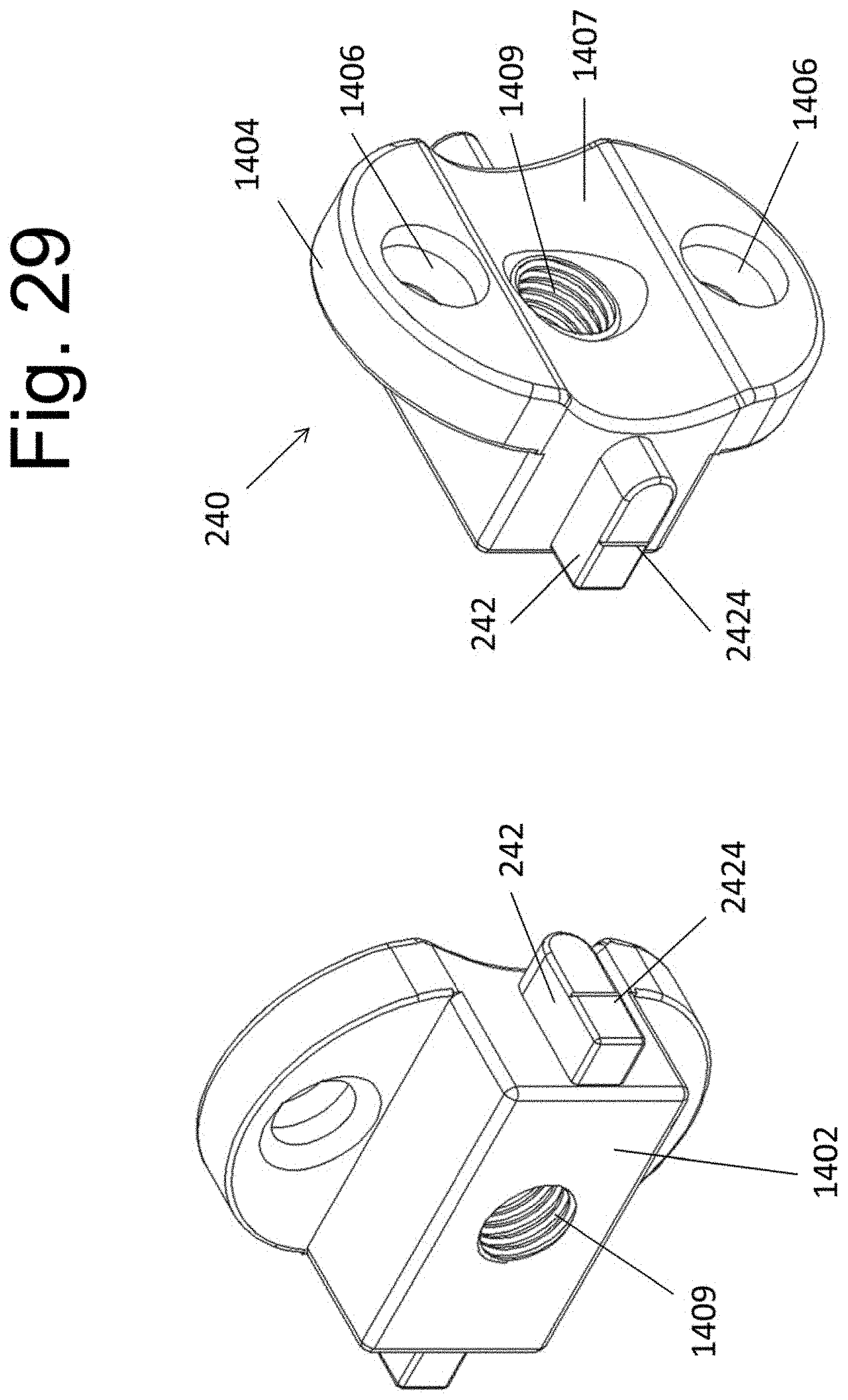
[0040] FIG. 29 illustrates an alternative implantable spacer 240.
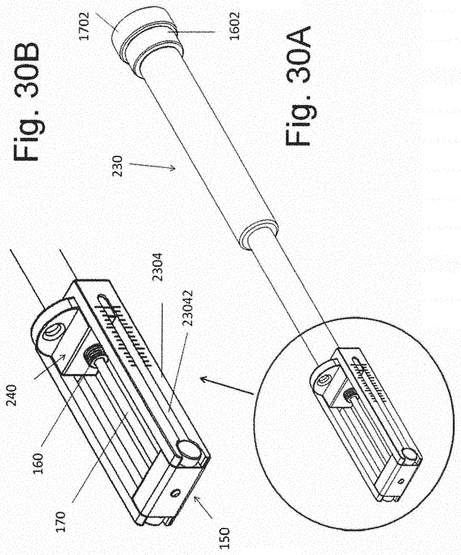
[0041] FIGS. 30A and 30B illustrate the assembly comprising the instrument 230 and the implantable spacer 240.
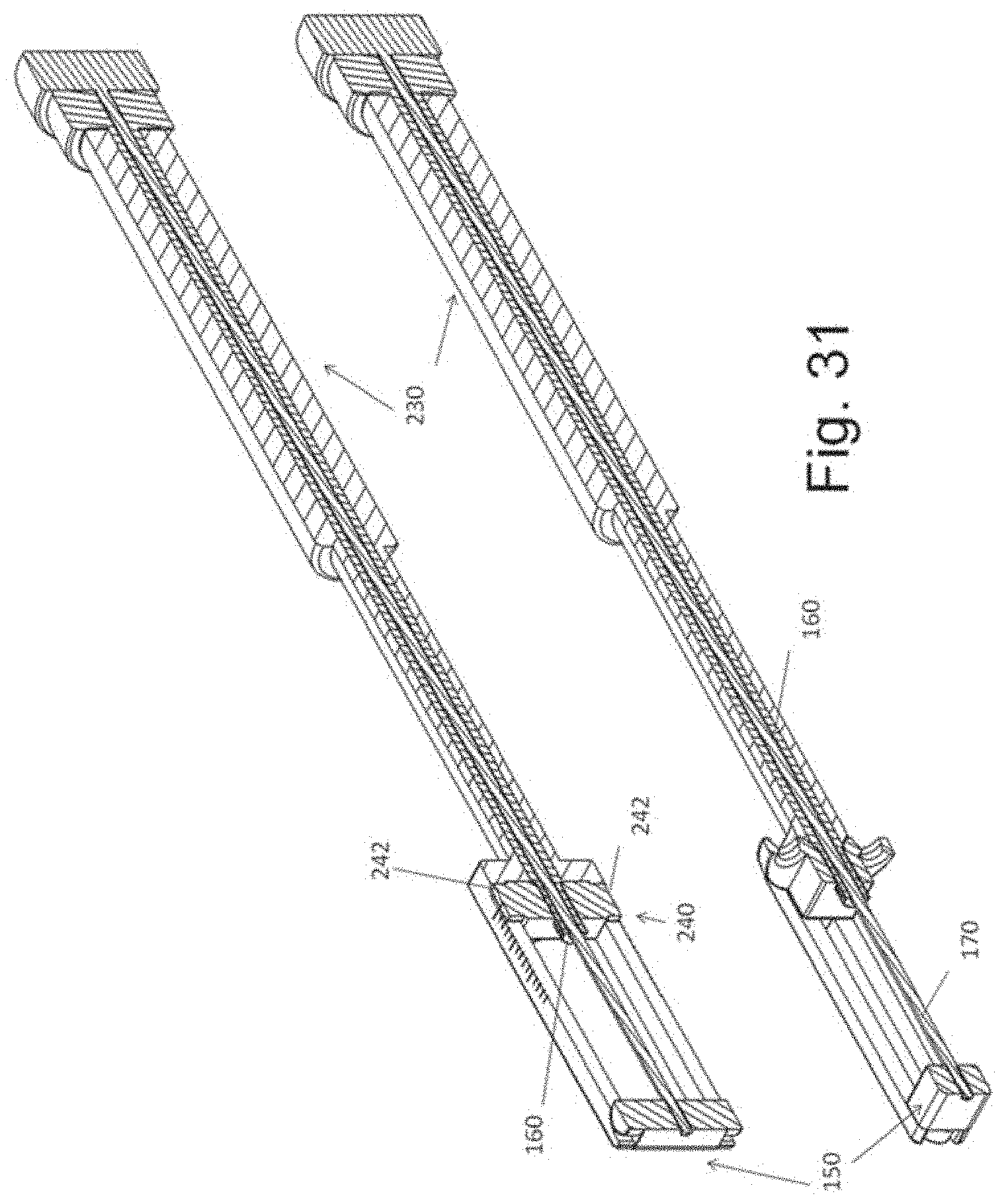
[0042] FIG. 31 illustrates sectional views of the assembly of FIG. 29.
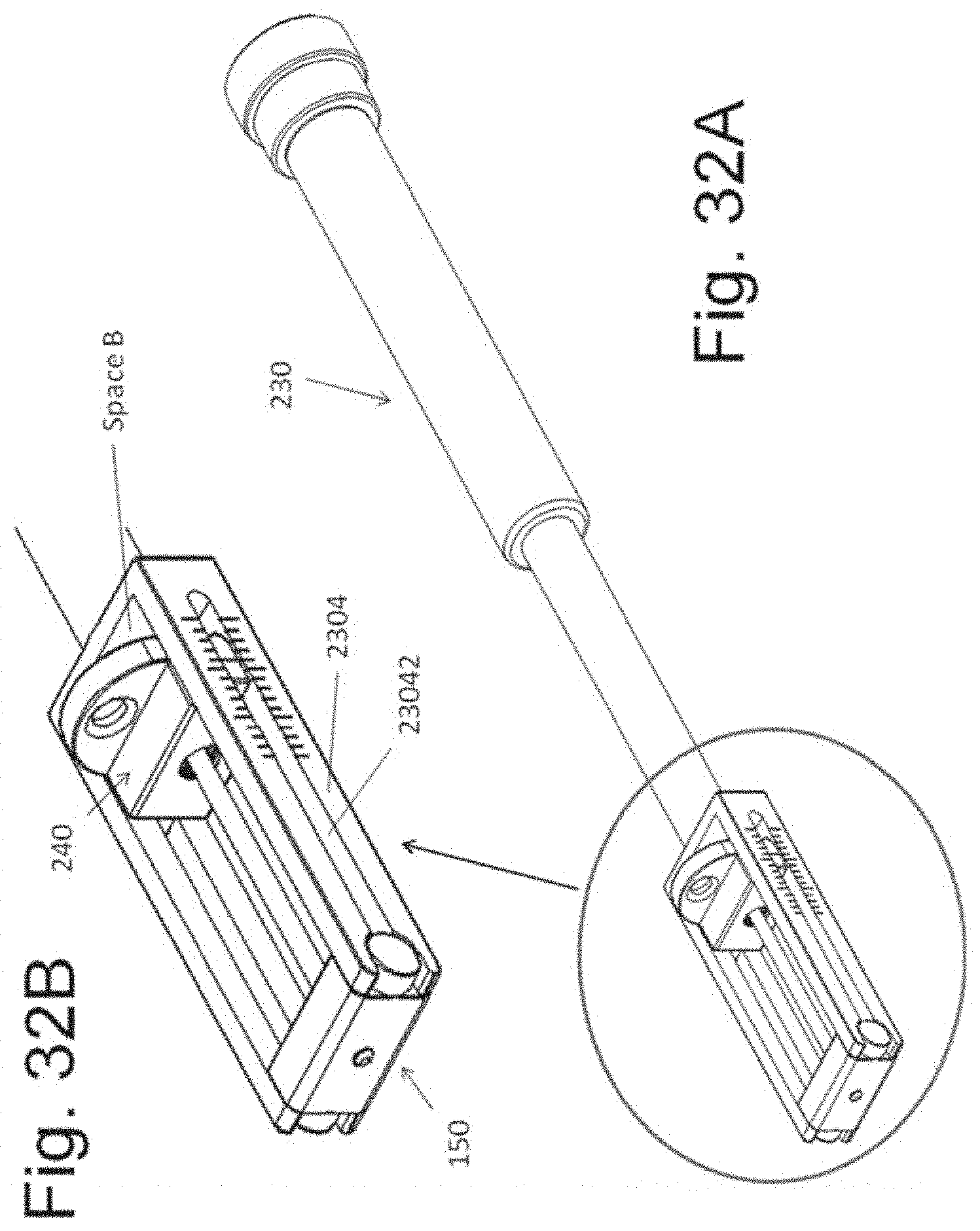
[0043] FIGS. 32A and 32B illustrate an exemplary instrument 230 configured to retain the implantable spacers 240 at a variable distance relative to the spacer 150; the distance between the implantable spacers can be read directly from the instrument 230.
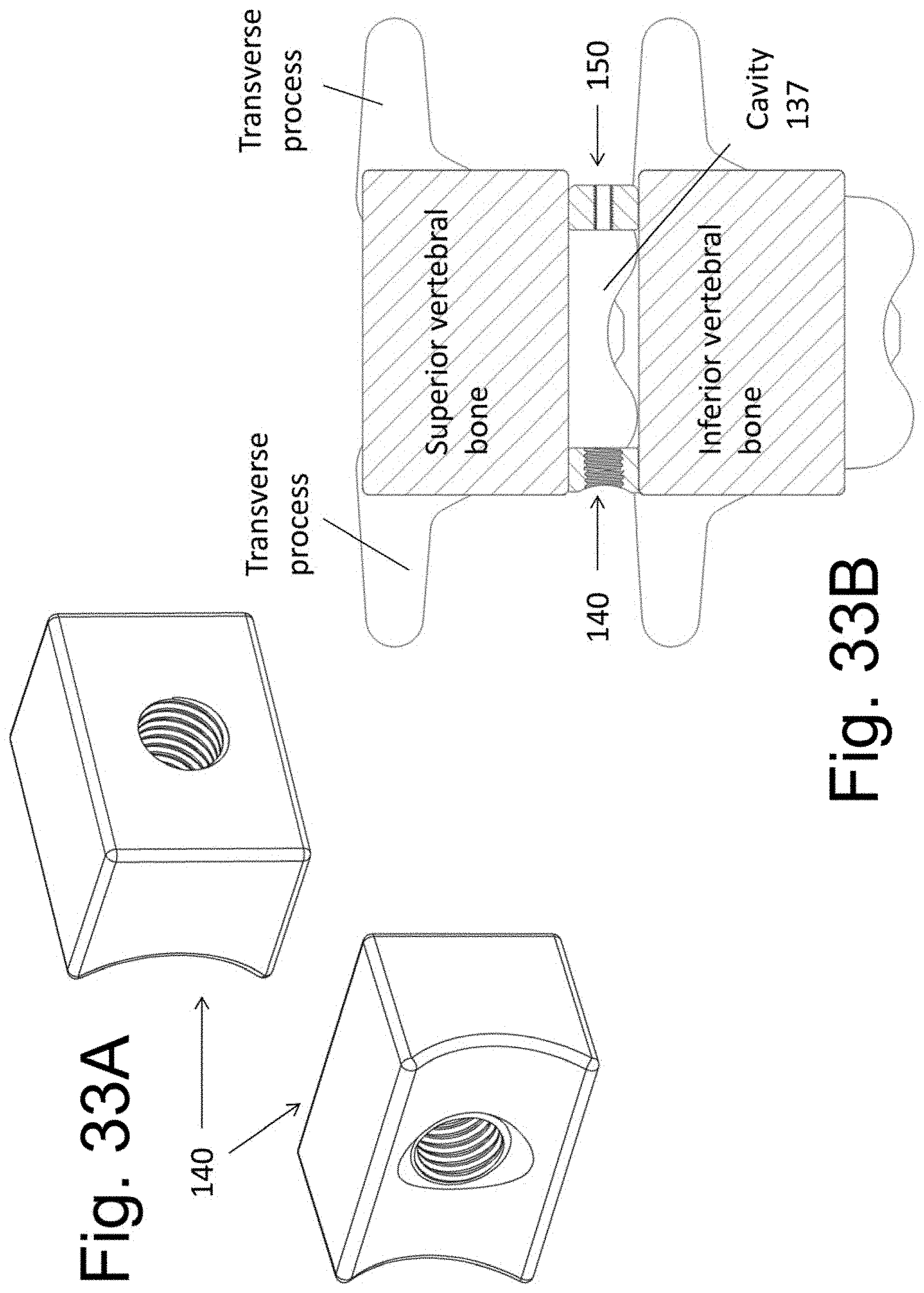
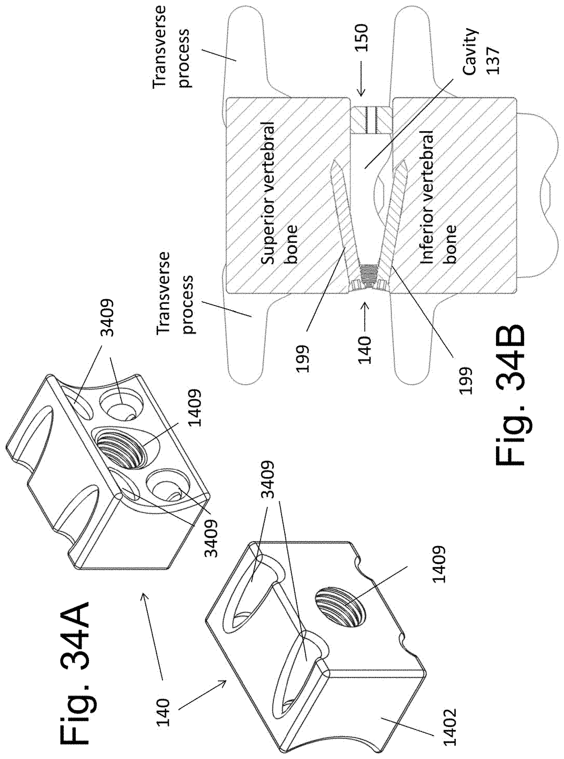
[0044] FIGS. 33A, 33B, 34A, and 34B illustrate alternative embodiments of the implantable spacer 140.
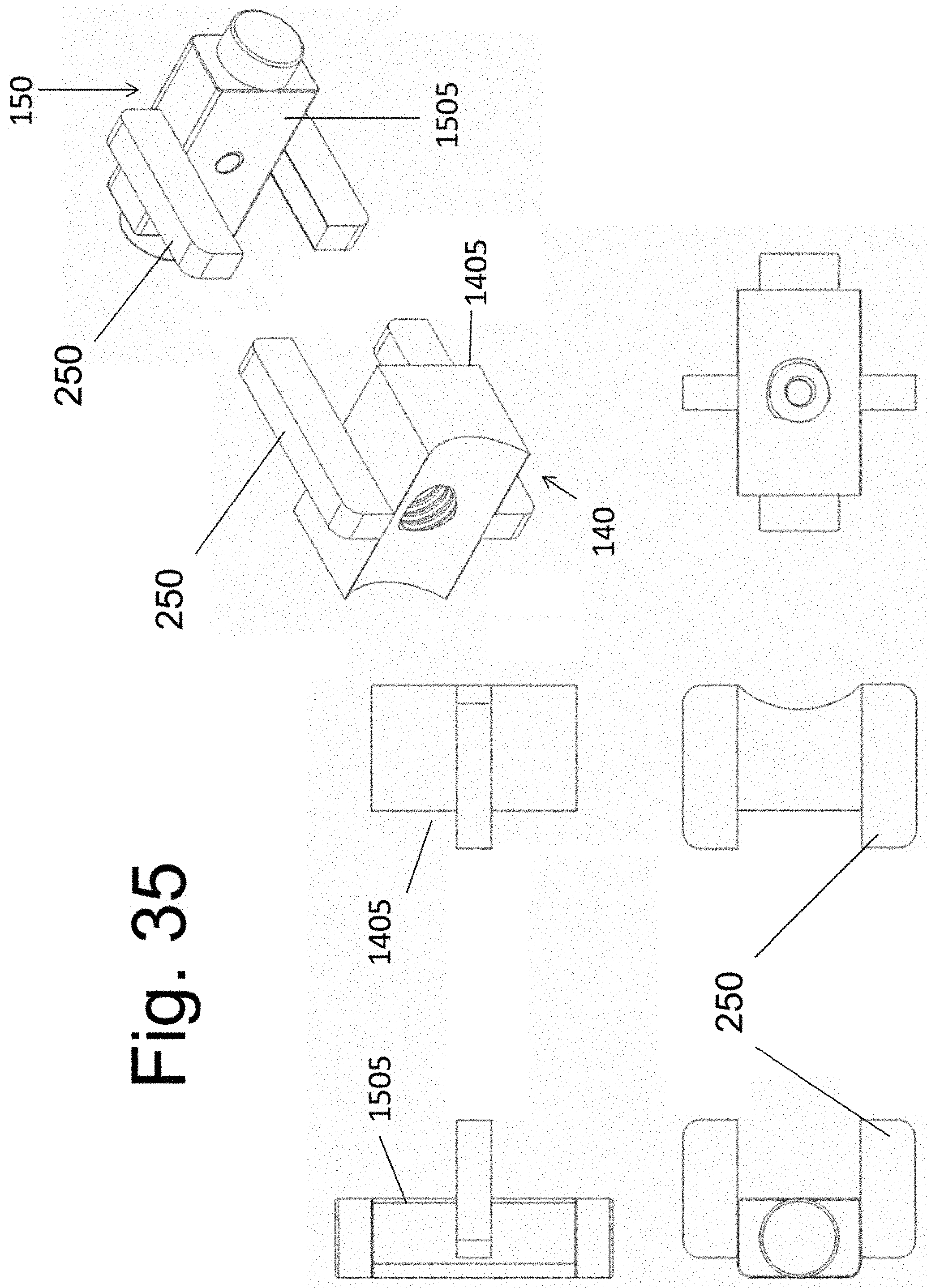
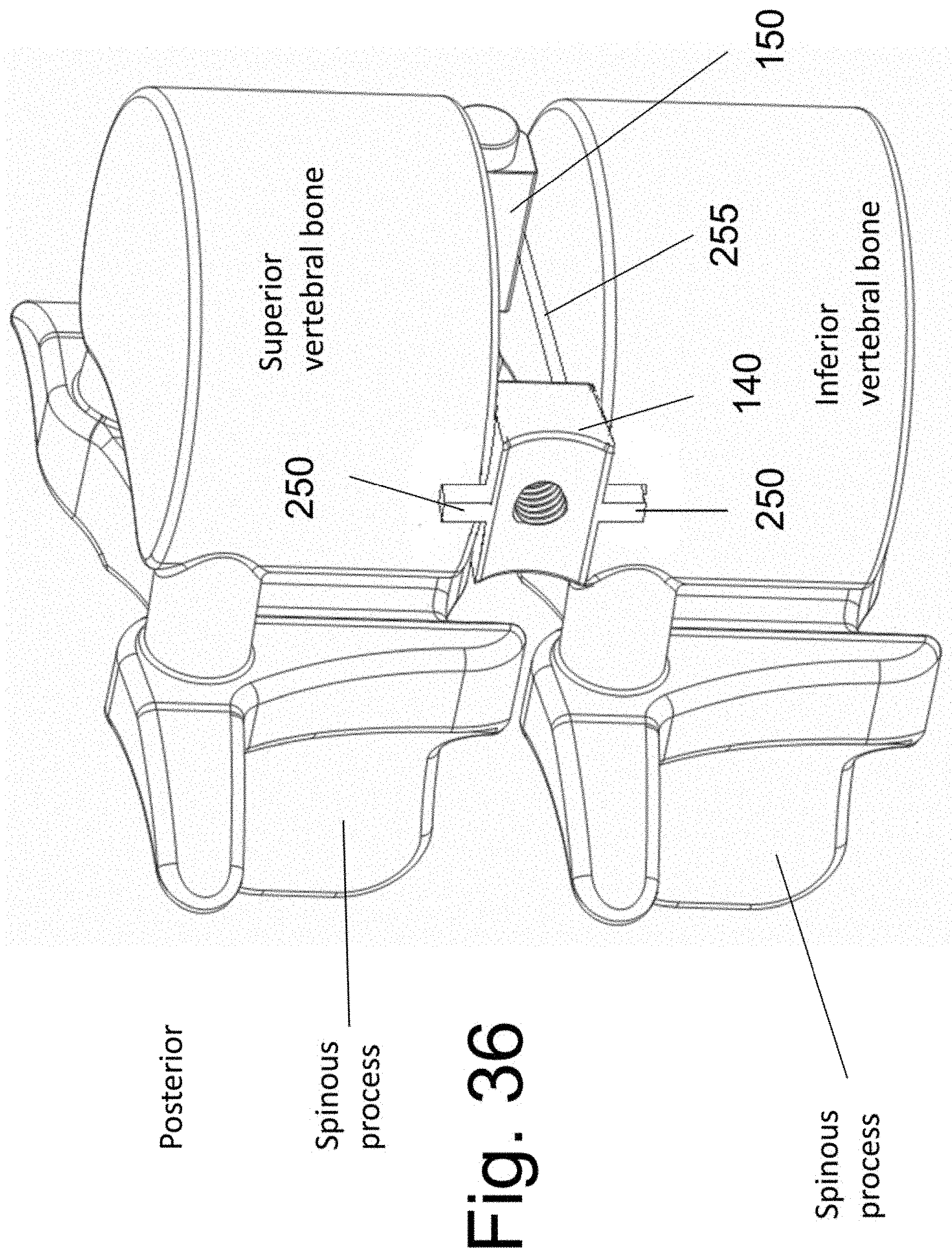
[0045] FIGS. 35 and 36 illustrate an additional embodiment of the implantable spacers.
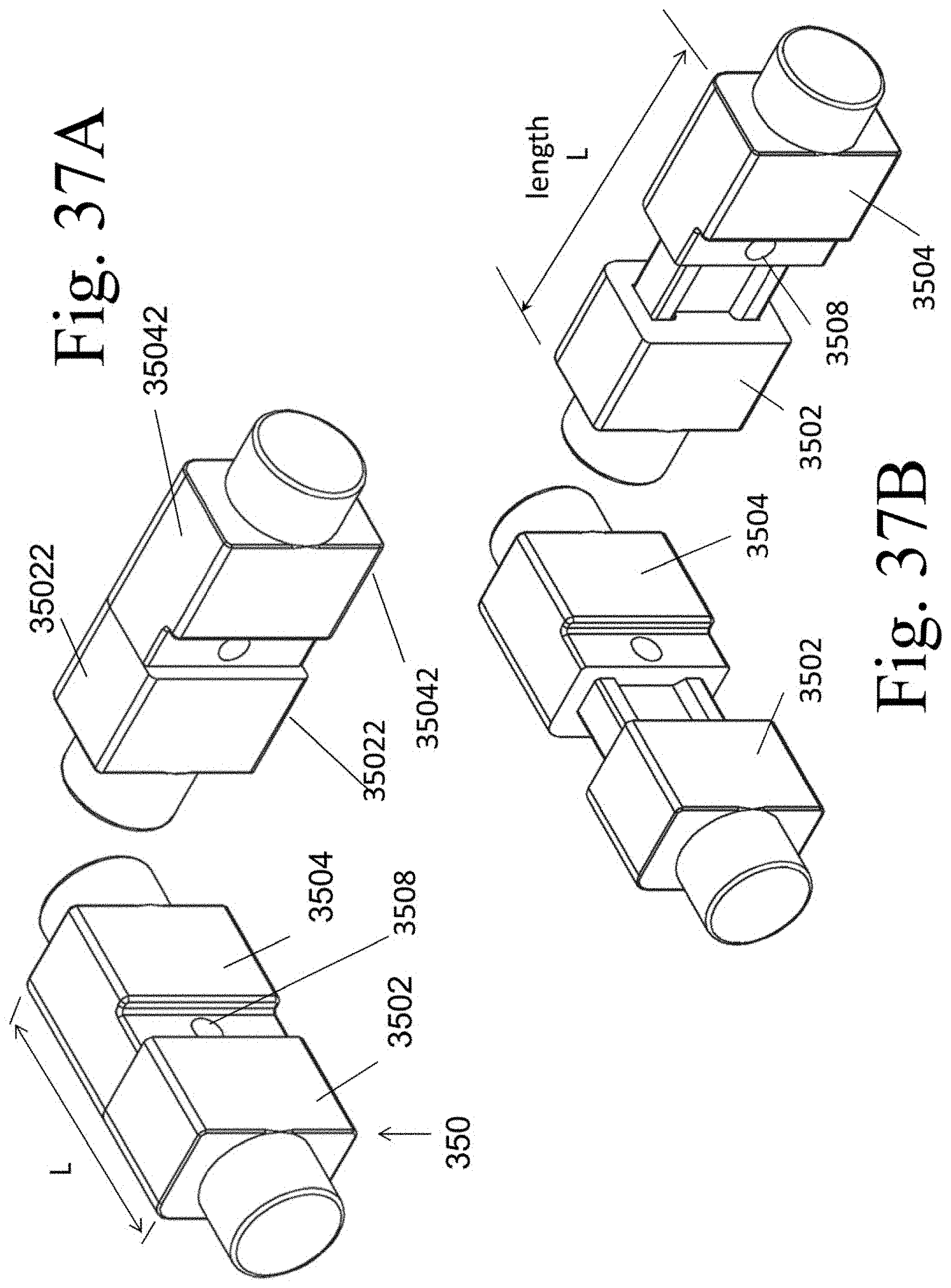
[0046] FIGS. 37A and 37B illustrate an exemplary implantable spacer 350 in an expanded and non-expanded configuration.
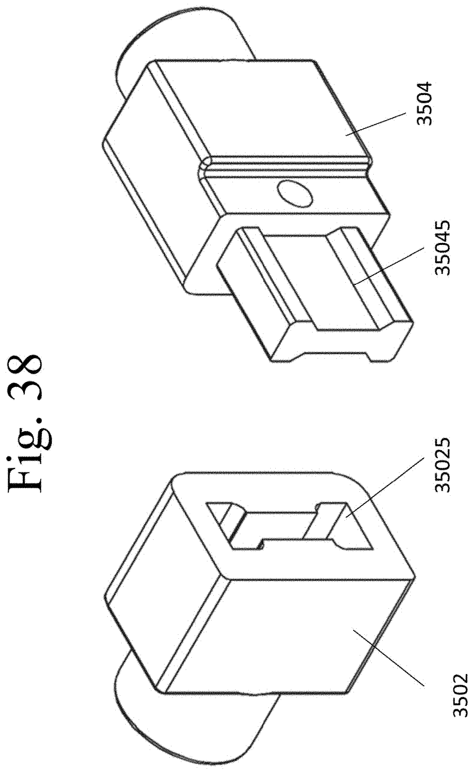
[0047] FIG. 38 illustrates a protrusion 35045 of segment 3504 and the complimentary bore 35025 of segment 3502.
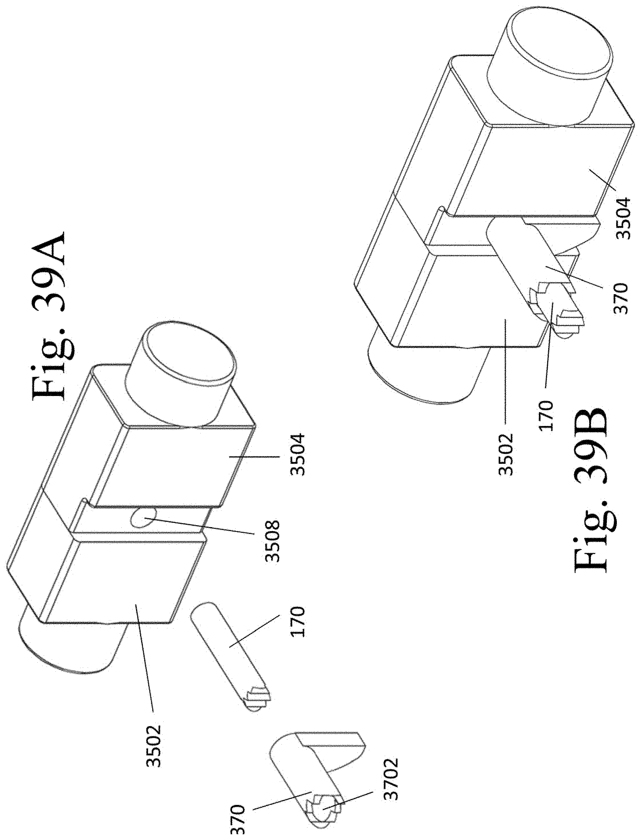
[0048] FIGS. 39A and 39B illustrate an exemplary screw 170 which is configure to compliment the bore 3508.
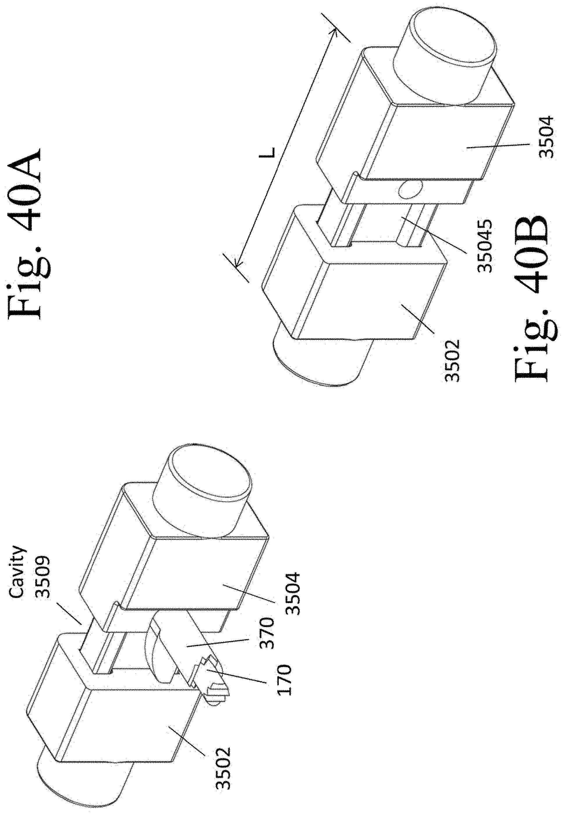
[0049] FIG. 40A illustrates exemplary rotation of the expander 370 relative to the spacer 350 to increase the length L of the implant 350.
[0050] FIG. 40B illustrates the expanded implant 350 after removal of screw 170 and expander 370.
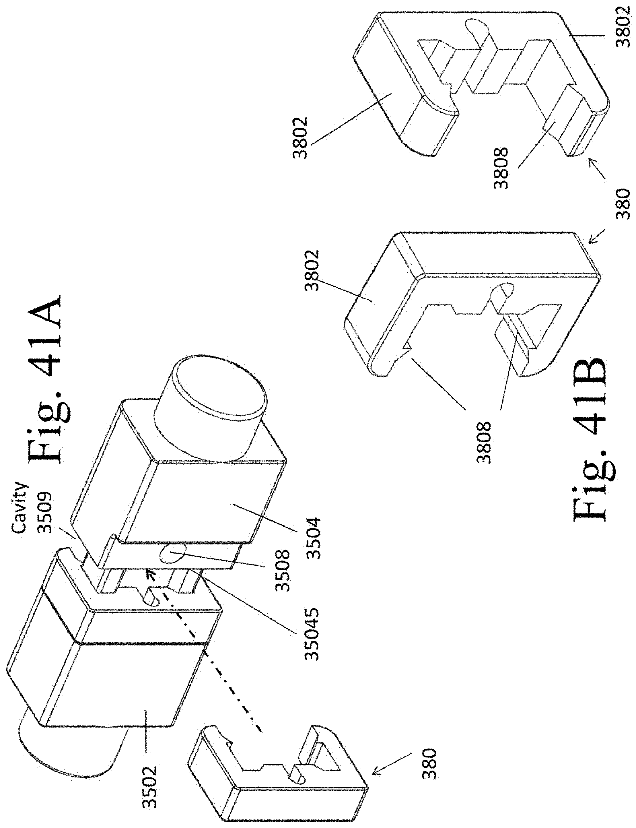
[0051] FIG. 41A illustrates an exemplary segment 380 coupled to an expanded spacer 350 and a second exemplary segment 380 positioned to be advanced into cavity 3509.
[0052] FIG. 41B illustrates an exemplary segment 380,
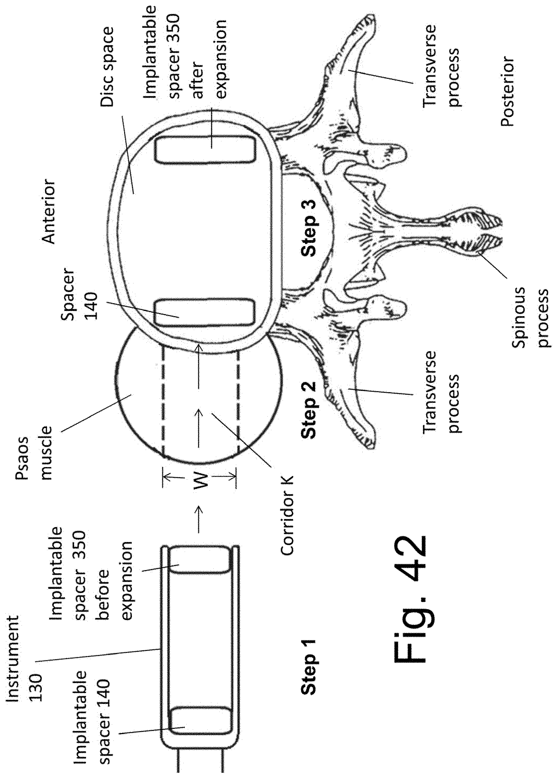
[0053] FIG. 42 illustrates an exemplary procedure for using the instrument 130 to attach the implantable spacer 350 prior to expansion.
DETAILED DESCRIPTION
[0054] In order to promote an understanding of the principles of the disclosure, reference is made to the drawings and the embodiments illustrated therein. Nevertheless, it will be understood that the drawings are illustrative and no limitation of the scope of the claims is thereby intended. Any such alterations and further modifications in the illustrated embodiments, and any such further applications of the principles of the disclosed devices as illustrated herein are contemplated as would normally occur to one of ordinary skill in the art.
DETAILED DESCRIPTION OF EXEMPLARY EMBODIMENTS
[0055] FIG. 1 is a diagrammatic representation of a spinal vertebral bone 802 in multiple views. For clarity of illustration, the vertebral bone of FIG. 1 and those of other illustrations presented in this application are represented schematically, and those skilled in the art will appreciate that actual vertebral bodies may include anatomical details that are not shown in these figures.
[0056] Further, it is understood that the vertebral bones at a given level of the spinal column of a human or animal subject will contain anatomical features that may not be present at other levels of the same spinal column. The illustrated vertebral bones are intended to generically represent vertebral bones at any spinal level without limitation. Thus, the disclosed devices and methods may be applied at any applicable spinal level.
[0057] Vertebral bone 802 contains an anteriorly-placed vertebral body 804, a centrally placed spinal canal and 806 and posteriorly-placed lamina 808. The pedicle (810) segments of vertebral bone 802 form the lateral aspect of the spinal canal and connect the laminas 808 to the vertebral body 804. The spinal canal contains neural structures such as the spinal cord and/or nerves. A midline protrusion termed the spinous process (SP) extends posteriorly from the medial aspect of laminas 808. A protrusion extends laterally from each side of the posterior aspect of the vertebral bone and is termed the transverse process (TP). A right transverse process (RTP) extends to the right and a left transverse process (LTP) extends to the left. A superior protrusion extends superiorly above the lamina on each side of the vertebral midline and is termed the superior articulating process (SAP). An inferior protrusion extends inferiorly below the lamina on each side of the vertebral midline and is termed the inferior articulating process (IAP). Note that the posterior aspect of the pedicle can be accessed at an indentation 811 in the vertebral bone between the lateral aspect of the SAP and the medial aspect of the transverse process (TP). In surgery, it is common practice to anchor a bone fastener into the pedicle portion of a vertebral bone by inserting the fastener through indentation 811 and into the underlying pedicle.
[0058] FIGS. 2A and 2B illustrate a functional spinal unit (FSU), which includes two adjacent vertebrae and the intervertebral disc between them. The intervertebral disc resides between the inferior surface of the upper vertebral body and the superior surface of the lower vertebral body. (Note that a space is shown in FIGS. 2A and 2B where intervertebral disc would reside.) FIG. 2A shows the posterior surface of the adjacent vertebrae and the articulations between them while FIG. 2B shows an oblique view. Note that the FSU contains a three joint complex between the two vertebral bones, with the intervertebral disc comprising the anterior joint. The posterior joints include a facet joint 814 on each side of the midline, wherein the facet joint contains the articulation between the IAP of the superior vertebral bone and the SAP of the inferior bone.
[0059] The preceding illustrations and definitions of anatomical structures are known to those of ordinary skill in the art. They are described in more detail in Atlas of Human Anatomy, by Frank Netter, third edition, Icon Learning Systems, Teterboro, N.J. The text is hereby incorporated by reference in its entirety.
[0060] In one aspect of the present disclosure, instruments and methods that permit a surgeon to position an implant assembly within an intervertebral disc space are provided. In an embodiment, the bone graft material is contained within the placement instrument that is used to deliver the implant to the implantation site. The placement instrument positions the bone graft material in a desired relationship to a spacer(s), wherein the latter is used to bear at least a portion of the vertical load transmitted across the implanted disc space. (The vertical load refers to the load that would normally be transmitted across the disc space of a subject standing erectly. It is understood that the vertical load experienced by an individual disc space will vary with the level of that disc space in the vertebral column. In general, more caudal disc space levels will experience higher vertical loads than more cephalad disc space levels.) The spacer(s) and bone graft material are delivered into the disc space in the desired configuration.
[0061] In one embodiment, the bone graft is positioned outside of one or more spacers that are collectively and concurrently delivered into the disc space by the placement instrument. In this embodiment, no additional bone graft material is enclosed within an internal cavity of any of the spacers. In another embodiment, the bone graft material is positioned within the placement instrument both on the outside of the one or more spacers and also within a internal cavity of at least one spacer.
[0062] In yet another embodiment, the bone graft material is positioned within the internal cavity of one or more spacers, but no additional graft material is positioned within the placement instrument and outside of the spacer(s).
[0063] While the device and the procedure are illustrated using a lateral procedure to position the implant assembly into the disc space of the lumbar spine, it is understood that the device may be used to position a implant assembly into the disc space at any level and using any approach to the spinal column.
[0064] In preparation for percutaneous placement of the implant into a spinal level, the patient can be, but is not necessarily, placed in a prone or lateral decubitus position. The level of the spine that is to be implanted can be localized on X-ray in at least one plane. After the customary sterile preparation of the operative site, the surgeon can localize an incision point on the skin that is substantially directly lateral to the spinal segment that will be implanted. FIG. 3 shows a schematic representation of the posterior aspect of a subject. The skin overlying the back is shown. The midline is labeled and approximates the mid-sagittal plane of the vertebral column. Lines Y show the lateral extent of the transverse processes of the spinal column. Assuming that the spinal level to be accessed is at line Z, the surgeon can make an incision at or about circle X.
[0065] FIG. 4 illustrates a cross sectional view of the torso (positioned prone) at the level of the lumbar spine. For clarity of illustration, the contents are represented schematically and those skilled in the art will appreciate that an actual cross section of the human torso may include anatomical details not shown in FIG. 4. A lateral corridor 105 can be made from the flank, through the psoas muscle 106 and onto the lateral aspect of the disc space at the spinal level to be implanted. An implant can be placed through the corridor 105 and into disc space or onto the spine. The procedure is known to those skilled in the art and known by differing names, such as the "XLIF" procedure (see "Extreme Lateral Interbody Fusion (XLIF): a novel surgical technique for anterior lumbar interbody fusion." By Ozgur, Aryan et al. in Spine J. 2006 July-August; 6(4):435-43, which is hereby incorporated by reference in its entirety.) Variations of the operation are also known as Direct Lateral Interbody Fusion (DLIF) and the like.
[0066] An instrument (not shown) is passed through corridor 105 and onto the lateral aspect of the psoas muscle 106. The instrument is advanced through the muscle and into the disc space. Since important nerve structures may transverse the psoas muscle, the instrument (and/or a probe or device placed through a channel of the instrument) is connected to an Electromyography (EMG) apparatus (or any other electrical system that is used to localize nerve tissue), and used, at least partially, as an EMG probe during advancement through the muscle. In this way, the advancement of the instrument through the psoas muscle is performed under EMG guidance. Under X-ray visualization, the instrument is placed into the disc space. At least a portion of the disc material is removed from within the disc space through the established corridor. After the discectomy is performed and the bony end plates have been decorticated and prepared, at least one spacer and bone graft material (and/or bone graft substitute) is placed within the evacuated portion of the disc space. With time, the graft material will form a bony bridge between the two vertebral bodies and fuse them. As described, the procedure is performed in a percutaneous manner and under x-ray. A wider incision may be employed and portions of the procedure, such as the discectomy, may be performed under direct vision and using minimally invasive surgical technique.
[0067] Instrument 130 is used to position at least one spacer into the partially evacuated disc space. (The implantation is preferably, but not necessarily, performed in a percutaneous manner.) The implanted spacer functions to bear at least a portion of the load transmitted through the disc space. Instrument 130 also places the bone graft or bone graft substitute (collectively called bone graft material) into the disc space. The bone graft material is delivered in prescribed spatial relationship to the spacer(s). In the illustrated embodiment, the spacer(s) will not contain an internal cavity configured to house a bone graft material. However, it is understood that one or more of the implanted spacers may alternatively comprise an internal cavity configured to house bone graft material, wherein the house bone graft material is in communication with each of the vertebral bones that border the implanted disc space.
[0068] An embodiment of instrument 130 is shown in FIGS. 5 and 6. Instrument 130 has handle 1302, side members 1304 and an indentation 1305 at one end of each side member 1304. Surface 1306 is positioned between side members 1304. A bore 1308 transverses handle 1302.
[0069] FIG. 7 shows instrument 130 and two spacer implants in the disassembled state while FIG. 8 shows the assembled device. Spacers (alternatively labeled "implant") 140 and 150 are attached to instrument 130 using screws 160 and 170, respectively. The assembly is shown in three planes in FIG. 9. Sectional views are shown in FIG. 10. Spacer 140 is shown in FIG. 1 while spacer 150 is illustrated in FIG. 12. Preferably, but not necessarily, each spacer does not have a medial to lateral dimension that is greater than one half of the medial to lateral dimension of the implanted disc space. That is, each of width A of spacer 140 (FIG. 11A) and width B of spacer 150 (FIG. 12) is less than on half of the value of the width W of the implanted disc space (the width of the disc space is the maximum disc space dimension in the coronal plane of the spine--as shown in FIG. 21B).
[0070] Implantable spacer 140 has central body 1402 that is inserted into the disc space and maintains the distance between the adjacent bodies and the height of the disc space. Body 1402 may be comprised of any material that is adapted for biological implantation, including a segment of bone (allograft or autograft that is harvested and shaped at the same operation) that is affixed onto a side plate member (as shown in FIG. 11A). In one variant, the upper and/or lower surfaces 14022 of body 1402 contain surface protrusions or textures (not shown) that increase fixation of these surfaces onto the abutting bone.
[0071] A side member 1404 is adapted to be positioned onto the side of each of the vertebral bodies. At least one bore 1406 is positioned within at least one side member 1404 and permits placement of bone screw into the side of at least one vertebral body. The surface (14042) that abuts the side surface of the vertebral bone may have one or more protrusions (not shown), such as, for example, spike, that penetrate and fixate into said bone. Spikes adapted for bone fixation are well known in the art and are shown in US 2004/0162558 and others. (The citation is hereby incorporated by reference in its entirety). A curvilinear surface 1407 permits interaction of the spacer 140 with curvilinear surface 1306 of instrument 130. A threaded bore hole 1409 is contained within central body 1402 of spacer 140 and, in assembly with instrument 130, accepts the threaded end of screw 160.
[0072] While each of end height K and end height L of body 1402 (FIG. 11) is shown as being of equal length, it is contemplated that each of heights K and L may alternatively be different. In this may, the implant may be used, for example to impart a greater height to the anterior disc space than the posterior disc space and impart a lordotic curvature onto the implanted FSU segment (FIG. 21A--in sagittal view). It is further contemplated that spacer 140 may be alternatively comprised of a substantially solid member (for example, a rectangular or trapezoid member that is similar to body 1402) without any side members 1404 that extend onto the side of vertebral bones.
[0073] Implantable spacer 150 has central body 1502 that is inserted into the disc space and maintains the distance between the adjacent bodies and the height of the disc space. Body 1502 may be comprised of any material that is adapted for biological implantation, including being at least partially comprised of a segment of bone (whether allograft or autograft). The upper and/or lower surfaces 15022 of body 1502 may contain surface protrusions or textures (not shown) that increase fixation of these surfaces onto the abutting bone. At least one side member 1504 is adapted to interact with indentation 1305 at one end of each side member 1304 of instrument 130. A threaded bore hole 1508 is contained within central body 1502 of spacer 150 and, in assembly with instrument 130, accepts the threaded end of screw 170.
[0074] While each of end height K and end height L of body 1502 (FIG. 12) is shown as being of equal length, it is contemplated that each of heights K and L may alternatively be different. In this way, the implant may be used, for example to impart a greater height to the anterior disc space than the posterior disc space and impart a lordotic curvature onto the implanted FSU segment (FIG. 21A--in sagittal view). Further, the heights of bodies 1402 and 1502 may be different so as to change the vertebral alignment in the coronal plane of the spine--such as, for example, in scoliosis. The latter is illustrated in FIG. 21B illustrates a coronal plane section of the vertebral bones that surround an implanted disc space. Note the coronal plane curvature created by the different sized implants 140 and 150.
[0075] FIGS. 13 and 14 illustrate how instrument 130 may be used to position implants 140 and 150 into the target disc space with a variable distance between them. FIGS. 9, 10, 13A and 14A illustrate implant 140 attached to screw 160 and threadedly attached with surface 1407 abutting surface 1306 of instrument 130. Note that the end segment 1602 of screw 160 is positioned between the end of instrument 130 and end 1702 of screw 170. With rotation of end 1602 in a first direction, implant 140 will be displaced towards implant 150 by the threads of screw 160. With rotation of end 1602 in an opposite direction, implant 140 will be moved away from implant 150 until surface 1407 abuts surface 1306 of instrument 130. In this way, instrument 130 may be used to position implants 140 and 150 into the target disc space with a variable distance between them. FIGS. 13B and 14B illustrate implant 140 having been displaced towards implant 150. Note that space A is now positioned between implant 140 and surface 1306 on instrument 130.
Method of Use
[0076] Patient positioning, incision placement, the surgical corridor used, and traversal of the psoas muscle (including under electrophysiological monitoring (EMG) and the like) were described above and will not be repeated herein.
[0077] FIG. 15 shows a diagrammatic representation of two vertebral bodies and an intervening disc space in multiple views. For clarity of illustration, the vertebral bodies are represented schematically and those skilled in the art will appreciate that actual vertebral bodies include anatomical details not shown in FIG. 15. As mentioned, at least a partial removal of the disc material is performed before implantation of the spacers 140 and 150 and bone graft material between them. The area of disc space that is evacuated of disc material may be slightly larger than the distance between the outer surfaces of side members 1304 of instrument 130. FIG. 16 illustrates the assembly of FIG. 9 (comprised of instrument 130, spacer 140, spacer 150, screw 160 and screw 170) inserted into the disc space between two vertebral bodies using a lateral approach (corridor 105, FIG. 4). Before insertion, a bone graft material is placed within cavity 137 that is contained between side members 1304, spacer 140, and spacer 150 in the assembled device. The bone graft material is at least partially delivered into the disc space while in cavity 137. In one embodiment, the bone graft material is contained with a cavity of those members that will be left implanted in the disc space. The graft material is contained in a cavity of the placement instrument and the instrument, upon removal from the disc space, leaves the graft material freely positioned within the disc space and in between spacer 140 and 150 (see FIGS. 19A and B). That is, in one embodiment, the bone graft material is not contained within an internal cavity of the implanted spacers themselves. FIG. 17A illustrates the insertion in multiple orthogonal planes.
[0078] In one exemplary embodiment, the width of the disc space is first measured. The width of the disc space, W (FIG. 22B), is equal to the greatest distance from a lateral side surface to an opposing lateral side surface of the target disc space when measured in a coronal plane of the disc space. The placement instrument is the selected so that the lateral length, L (FIGS. 6 and 9), from surface 1306 to the end is substantially equal to the width, W, of the disc space. In this way, when spacers 140 and 150 are affixed to the instrument 130, the total distance from the outside surface of spacer 140 to the outside surface of spacer 150 is substantially equal to the width, W, of the disc space. It is appreciated that in one embodiment the length L is at least equal to the width W. in another embodiment, the length L is slightly greater than the width W, in order to enable the device to allows for some accommodation of length--as is shown in FIGS. 14B and 28 through 32.
[0079] Note that at least a segment of each of spacers 140 and 150 may be positioned overlying the epiphyseal ring of the vertebral bones immediately superior and inferior (i.e., that border) the implanted disc space. The epiphyseal ring is illustrated in FIG. 17B, wherein an view of the superior aspect of a vertebral bone is shown (the numbers are as shown in FIG. 1). The epiphyseal ring forms the strongest portion of the superior and inferior surfaces of the vertebral body, which are the vertebral surfaces that border the intervertebral disc spaces. (The epiphyseal ring is more fully discussed in: The epiphyseal ring: a long forgotten anatomical structure with significant physiological function. Dar G, et al. Spine. 2011 May 15; 36(11):850-6. The article is hereby incorporated by reference in its entirety).
[0080] A cross sectional view (in the coronal plane of the spine) is shown in FIG. 17B. Note that members 1406 abut the lateral aspect of the vertebral bodies. Each of spacers 140 and 150 are on opposing sides of the disc space. Cavity 137 is packed with bone graft material and rests between the two spacers 140 and 150, wherein, in one embodiment, the bone graft material is not contained within a spacer cavity. (It is also contemplated that, in an embodiment, at least one of spacers 140 and 150 may contain a cavity for bone graft material--in addition to the bone graft material contained between then in cavity 137.)
[0081] Bone screws 152 are placed through bore holes 1406 and into the underlying bone. Screws 170 and 160 are unthreaded and removed. Instrument 130 is then removed, leaving the bone graft material within the evacuated disc space. FIGS. 19A and 19B illustrate the implanted spacer (the bone graft material resides between the spacers). In an alternative screw trajectory, shown in FIG. 20, the bone screws are aimed so that the distal aspect of at least one bone screw is aimed towards the disc space. In an embodiment, the distal end of at least one screw is anchored into spacer 150. (Note that bores 1406 of implantable spacer 140 permit placement of the bone screws in the trajectory of FIG. 19B or 20. That is, the same device embodiment permits variable trajectory.)
[0082] Preferably, but not necessarily, a device member and/or feature may be added to lock the bone screws to spacer 140. Plate-to-screw locking features are well known in the art and any applicable such feature/device may be used here. An illustrative example embodiment is shown in FIG. 23. Locking plate 190 has a first surface 192 with curvilinear central protrusion 1922 that is adapted to face (but not contact) surface 1407 of spacer 140. A non-threaded bore hole 1924 is adapted to accept a locking screw 196. When seated, the threaded end of screw 196 interacts with complimentary threads of bore 1409 of spacer 140. At least one additional protrusion 1927 extends from surface 192. In use, protrusion 1927 is adapted to forcefully abut the (head) portion of a bone screw 152 that reside within bore hole 1406. In this way, advancement of locking screw 196 into threaded hole 1409 provides a force that drives protrusion 1927 into bone screw 152 and immobilizes the bone screw relative spacer 140. The implanted locking plate 190 and locking screw 196 are shown in FIG. 24. A sectional view with locking plate 190 in the deployed position is shown in FIG. 25. Note that the locking mechanism locks both the screw above and the screw bellow the implanted disc space.
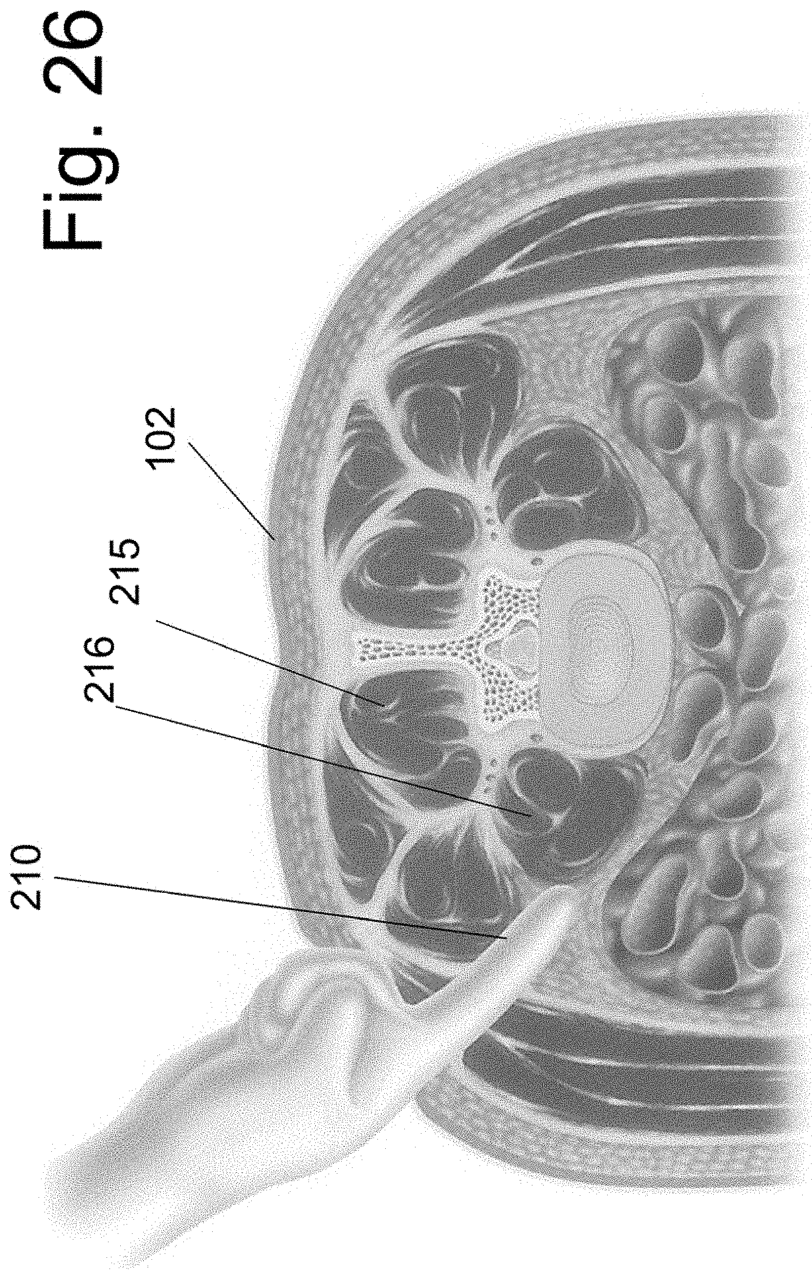
[0083] While use of instrument 130 and attached spacers has been illustrated in a straight lateral approach to the inter-vertebral disc space, the devices may be used in an anterior, posterior, oblique or any other known approach to the disc space. Further, the device may be easily configured for use in a curvilinear approach to the disc space. An illustrative example of a curvilinear approach to the disc space is shown in FIG. 26. In preparation for percutaneous placement of an orthopedic implant into a spinal disc space, the patient is placed in the prone position with spine and skin 102 in the superior position. The level of the spine that is to be implanted is localized on X-ray in at least one plane. After the customary sterile preparation of the operative site, the surgeon localizes an incision point that is lateral to the paraspinal muscles (the erector spinae muscle group 215 and/or others, for example) but not directly lateral to the side of the disc space. At least one finger 210 may be placed into the retro-peritoneal space and the lateral aspect of the psoas muscle 216 is palpated, as shown in FIG. 26. Alternatively, the surgeon can identify the psoas muscle by inserting an instrument instead of using direct digital palpation.
[0084] A curvilinear instrument 205 is shown in FIG. 27A. Instrument 205 is similar to instrument 130 but contains a curvilinear connection 2053 between the handle 2052 and the end segment that attaches the implants (the end segment contains side members 2054). As in the prior embodiment of FIGS. 9 and 10, member 260 affixes implant 140 to the instrument 205, whereas member 270 affixes implant 150 to the instrument 205. Member 260 has a first end 2602, an opposing threaded end and is at least partially malleable there between. Similarly member 270 has a first end 2702, an opposing threaded end and is at least partially malleable there between. As shown in the section view of FIG. 27b, members 260 and 270 are malleably configured to be positioned within the substantially linear portion of handle 2302 and also within the substantially non-linear portions of connection 2303.
[0085] FIGS. 13 and 14 illustrated how instrument 130 can retain each of spacers 140 and 150 at a variable distance from one another. FIGS. 28 to 32 illustrate a device embodiment wherein the distance between each of implants 140 and 150 is displayed by the instrument. That is, the current embodiment differs from the prior embodiment in that it contains an indicator of distance between implant 140 and 150. Whereas the distance between the implants 140 and 150 of the prior was determined by measuring that distance with a separate measuring device (ruler, caliper, and the like), the current embodiment contains a distance indicator.
[0086] FIG. 28 illustrates an exploded view of the current embodiment. The exploded view is similar to that of FIG. 7. Member 150, 170 and 160 are unchanged. Instrument 130 is replaced by instrument 230, wherein side members 2304 differ from side member 1304 in that each member 2304 contains a full thickness channel 23042 that extends proximally towards curvilinear surface 1306 from end indentation 1305. (A magnification of the end segment on instrument 230 is also shown in FIG. 28.) Markings are displayed on the outer side surface of each member 2304, from which the distance between implant 140 and 150 may be ascertained. While the markings are shown as "hatch marks" in the illustrations, it is understood that numbers, letters or any other notation may be used to indicate the distance of the marking from implant 150. The notations may express distance in a known unit of measure or they may use an arbitrary scale that is disclosed to the user in the instrument's instruction manual.
[0087] Implant 240 is illustrated in FIG. 29. Because it's substantially similar to implant 140 (FIG. 11), the same numbering scheme is used to illustrate it. It differs from implant 140 in having a side protrusion 242 on each side of the implant. Each protrusion 242 is sized and shaped to slidably move in one of each channel 23042 of instrument 230. A marking 2424 is found on the outer side surface of protrusion 242 and functions as a pointer that displays implant 242's position relative to the markings on the side surface side member 2304 of instrument 230. In this way, marking 2424 can be used to directly read the distance between implant 150 and 240.
[0088] The device is show in the assembled configuration in FIG. 30 and in cross section in FIG. 31. In FIG. 32, screw 160 has been rotated (via end 1602) and implant 240 has been moved towards implant 150 and away from curvilinear surface 1306. With movement, space B is now positioned between implant 240 and surface 1306. Comparison of FIGS. 30B and 32B show the movement of marking 2424 relative to the side markings of member 2304.
[0089] As previously disclosed, spacer 140 need not have a side member 1404 for attachment onto the side of the vertebral bones. FIG. 33A illustrates spacer 140 without either side members 1404. In this embodiment, the totality of the spacer 140 may be contained within the implanted disc space. FIG. 33B shows the section through the implanted vertebral bones and disc space.
[0090] FIG. 34 illustrate a spacer 140 that is similar to that of FIG. 33 but is configured to contain bore holes 1409 within body 1402, wherein said bores are configured to accept bone screws 199 that can anchor the spacer 140 directly into the adjacent vertebral bones. At least two bore holes 1409 are positioned within implant 140 so that at least one bone screw 199 is anchored into each of the vertebral bones above and below the implanted disc space. The screws are not placed into bone in a parallel trajectory, so as to enhance the fixation strength of spacer 140. The implanted spacer 140 may be contained within the disc space and may have no additional member positioned to abut additional side surfaces of the vertebral bones. While not specifically illustrated, each screw may be further locked to spacer 140 after implantation. Many screw to plate locking mechanism are known in the art and any applicable mechanism may be employed. The implanted device is shown in FIG. 34B.
[0091] FIG. 35 illustrates an alternative embodiment of the implantable spacer implants. An extension member 250 is attached to the top (and/or bottom or side) surface to at least one of implant 140 and 150. When attached to the top and/or bottom surface of at least one implant, the extension can be positioned into a cut bone channel 255, as shown in FIG. 36. The extension may be wholly contained within the cut channel 255 or some segment of said extension 250 may extend out of the vertebral bone, such as, for example, into the disc space. The extension 250 is less the total width (when measured at its greatest extent) of the upper and/or lower vertebral bone. The width W is shown in FIG. 22B. While extension 250 is shown attached to the upper and lower surface of the implant in FIGS. 35 and 36, it is alternatively attached to a side surface (such as surface 1505 of implant 150, or surface 1405 of implant 140) of said implants and rest at least partially within the disc space on implantation. In this embodiment, extension 250 would at least partially enclose bone graft cavity 137.
[0092] An alternative embodiment of member 150 is illustrated as implantable spacer 350. In this embodiment, spacer 350 is of variable length and is comprised of two slidable segments 3502 and 3504. The body of slidable segment 3502 cooperatively interdigitates with the body of slidable segment 3504. The upper and/or lower surfaces 35022 and 35042 may contain surface protrusions or textures (not shown) that increase fixation of these surfaces onto the abutting bone. A threaded bore hole 3508 (threads not shown) is contained within the body of slidable segment 3505, wherein the bore hole receives the threaded end of screw 170.
[0093] FIG. 37A illustrates implantable spacer 350 in a non-expanded configuration whereas FIG. 37B shows spacer 350 after expansion. (Note that length L is greater in the expanded state than in the non-expanded state.) FIG. 38 shows protrusion 35045 of segment 3504 and the complimentary bore 35025 of segment 3502. FIG. 39 illustrate screw 170, wherein the distal end is configured to have threads complimentary to those of bore 3508 (threads not shown). In addition, cam expander 370 is also shown, wherein expander 370 has a bore 3702 adapted to accept screw 70 therein. Note that the distal end alone of each of screw 170 and expander 370 is shown. However, it is contemplated that a placement instrument 130 (not shown in FIG. 39) is configured to couple with spacer 350. Unlike the device of FIGS. 7-10, screw 170 would be positioned inside expander 370, and the latter would be in turn positioned within screw 160.
[0094] FIG. 40 A illustrates that rotation of expander 370 relative to spacer 350 will drive segment 3502 away from segment 3504 and increase the length L of implant 350. FIG. 40B shows the expanded implant 350 after removal of screw 170 and expander 370.
[0095] The expanded spacer may be left as shown in FIG. 40B or an additional segment 380 may be attached to spacer 350 within the cavity 3509 created by the separation of segments 3502 and 3504. The addition of segment 380 provides more bone contact/abutment surface than expanded spacer 350 alone, since top and bottom surfaces 3802 of segment 380 will at least partially fill cavity 3509. FIG. 41B illustrates segment 380, whereas FIG. 41A shows one segment 380 coupled to expanded spacer 350 and a second segment 380 positioned to be advanced into cavity 3509. Teeth 3808 are used to lock segment 380 onto extension 35045 on segment 3504.
[0096] While each of the segment 380 can be separate members that are added to expanded spacer 350 (as shown), they may alternative be wedge-shaped segments that are implanted as a sub-segment of implant 350, wherein advancement of the wedge-shaped segment between segments 3502 and 3504 is performed after positioning of spacer 350 into the disc space, and wherein the advanced segment 380 both creates a cavity 3509 and fills it in (this embodiment is not shown).
[0097] In use, the implantable spacer 350 is configured to be passed though the psoas muscle while in a first configuration and then to expand within the disc space to a second configuration, wherein the length of spacer 350 is greater in the second configuration than in the first configuration. (The length of the device refers to long axis of the spacer, which, in use, is substantially positioned in the direction of a sagittal plane through the implanted disc space and measured in the anterior to posterior direction.)
[0098] FIG. 42 schematically illustrates the exemplary procedure, wherein instrument 130 attaches implantable spacer 350 prior to expansion (as shown in FIG. 37A) and then guides said spacer 350 through Corridor K of the psoas muscle. After spacer 350 is positioned within the target disc space, it is transitioned into the second configuration (as shown in FIG. 37B), wherein the second configuration is of greater length than the first spacer configuration. While spacer 350 is shown in both the expanded and non-expanded state in FIG. 42, it is to be understood that three different steps of the procedure are illustrated and not two separate spacers 350. That is, step 1 shows spacers 140 and 350 attached instrument 130 and positioned within the body cavity of the individual but is outside of the spine and the psoas muscle. In step 2, spacers 140 and 350 traverse the psoas muscle thought corridor K (instrument not shown while in the muscle). In step 3, spacers 140 and 350 have been positioned at opposing side of implanted disc space (and sitting on the epiphyseal ring) and transitioned into the expanded state--with subsequent complete removal of instrument 130. Note that the length of spacer 350 (as measured in the anterior to posterior plane of the disc space) in the second configuration is greater than the width W of corridor K, through which spacer 350 traversed the psoas muscle while being implanted into the disc space.
[0099] Note that spacer 140 is also shows as having been expanded to a greater length after being positioned within the disc space. While not separately illustrated, it is understood that spacer 140 can be made to expand in a manner similar to that illustrated for spacer 350. It is recognized, however, that many other mechanisms can be used to produce implantable spacers of expandable length. In one embodiment, the width of the expandable spacer (as measured in the coronal plane of the spine) may be less or equal to the width of the non-expanded spacer. In another embodiment, the width my greater in the expanded state than in the non-expanded state. That is, the width may change with transition from the first to the second configuration or it may remain constant.
[0100] In the herein-described exemplary embodiment of the method of device use, at least two implantable spacers are coupled to an implantation instrument (such as, for example, instrument 130) wherein at least one of the implantable spacers is configured to have an expandable length. The spacer width may be changeable or it may remain constant. The spacers are not directly attached to one another but are at least partially separated by a cavity configured to house bone graft material. The bone graft material is positioned outside at least one of said implantable implants but within a cavity of the implantation instrument. A direct lateral corridor (such as corridor 105; FIG. 4) to the target disc space is used to implant the spacers. (Note that trajectories other than a direct lateral approach may be alternatively used.) In the lumbar spine, the psoas muscle must be traversed in order to position the spacers in the target disc space. After placement of the spacers in the disc space, the at least one expandable spacer is increased in length and the placement instrument is removed from the disc space. In this way, a spacer is positioned on opposing lateral ends of the disc space with the bone graft material positioned there between. At least one of the implanted spacers has a length greater than the trans-psoas corridor used to deliver said spacer to the target disc space in one embodiment. At least one of the implanted spacers does not contain an internal cavity that also contains or is configured to contain bone graft material.
[0101] The disclosed devices or any of their components can be made for example of any biologically adaptable or compatible materials. Materials considered acceptable for biological implantation are well known and include, but are not limited to, stainless steel, titanium, tantalum, combination metallic alloys, various plastics, resins, ceramics, biologically absorbable materials and the like. Any components may be also coated/made with nanotube materials to further impart unique mechanical or biological properties. In addition, any components may be also coated/made with osteo-conductive (such as deminerized bone matrix, hydroxyapatite, and the like) and/or osteo-inductive (such as Transforming Growth Factor "TGF-B," Platelet-Derived Growth Factor "PDGF," Bone-Morphogenic Protein "BMP," and the like) bio-active materials that promote bone formation. Further, any surface may be made with a porous ingrowth surface (such as titanium wire mesh, plasma-sprayed titanium, tantalum, porous CoCr, and the like), provided with a bioactive coating, made using tantalum, and/or helical rosette carbon nanotubes (or other carbon nanotube-based coating) in order to promote bone in-growth or establish a mineralized connection between the bone and the implant, and reduce the likelihood of implant loosening. The system or any of its components can also be entirely or partially made of a shape memory material or other deformable material. Lastly, any of the implanted spaces that are disclosed may be partially or completely made out of bone and/or bone graft material.
[0102] It will be recognized that while certain aspects of the disclosure are described in terms of a specific sequence of steps of a method, these descriptions are only illustrative of the broader methods thereof, and may be modified as required by the particular application. Certain steps may be rendered unnecessary or optional under certain circumstances. Additionally, certain steps or functionality may be added to the disclosed embodiments, or the order of performance of two or more steps permuted. All such variations are considered to be encompassed within the present disclosure and claimed herein.
[0103] While the above detailed description has shown, described, and pointed out novel features of the disclosure as applied to various embodiments, it will be understood that various omissions, substitutions, and changes in the form and details of the device or process illustrated may be made by those skilled in the art without departing from the disclosure. The foregoing description is of the best mode presently contemplated. This description is in no way meant to be limiting, but rather should be taken as illustrative of the general principles. The scope of the present disclosure should be determined with reference to the claims.
* * * * *
D00000
D00001
D00002
D00003
D00004
D00005
D00006
D00007
D00008
D00009
D00010
D00011
D00012
D00013
D00014
D00015
D00016
D00017
D00018
D00019
D00020
D00021
D00022
D00023
D00024
D00025
D00026
D00027
D00028
D00029
D00030
D00031
D00032
D00033
D00034
D00035
D00036
D00037
D00038
D00039
D00040
D00041
D00042
D00043
D00044
XML
uspto.report is an independent third-party trademark research tool that is not affiliated, endorsed, or sponsored by the United States Patent and Trademark Office (USPTO) or any other governmental organization. The information provided by uspto.report is based on publicly available data at the time of writing and is intended for informational purposes only.
While we strive to provide accurate and up-to-date information, we do not guarantee the accuracy, completeness, reliability, or suitability of the information displayed on this site. The use of this site is at your own risk. Any reliance you place on such information is therefore strictly at your own risk.
All official trademark data, including owner information, should be verified by visiting the official USPTO website at www.uspto.gov. This site is not intended to replace professional legal advice and should not be used as a substitute for consulting with a legal professional who is knowledgeable about trademark law.