Methods Of Molding Intraocular Lenses
Webb; R. Kyle ; et al.
U.S. patent application number 15/931289 was filed with the patent office on 2020-10-29 for methods of molding intraocular lenses. The applicant listed for this patent is AcuFocus, Inc.. Invention is credited to Daniel David Siems, Nicholas Tarantino, R. Kyle Webb.
| Application Number | 20200337831 15/931289 |
| Document ID | / |
| Family ID | 1000004954006 |
| Filed Date | 2020-10-29 |


View All Diagrams
| United States Patent Application | 20200337831 |
| Kind Code | A1 |
| Webb; R. Kyle ; et al. | October 29, 2020 |
METHODS OF MOLDING INTRAOCULAR LENSES
Abstract
Intraocular implants and methods of making intraocular implants are disclosed. The intraocular implant can include a mask adapted to increase depth of focus. The method of manufacturing the implant can include filling an annular mask-forming trough with an opaque mask material and adding an optically transmissive optic material over the opaque mask material.
| Inventors: | Webb; R. Kyle; (Carlsbad, CA) ; Tarantino; Nicholas; (Capistrano Beach, CA) ; Siems; Daniel David; (Aliso Viejo, CA) | ||||||||||
| Applicant: |
|
||||||||||
|---|---|---|---|---|---|---|---|---|---|---|---|
| Family ID: | 1000004954006 | ||||||||||
| Appl. No.: | 15/931289 | ||||||||||
| Filed: | May 13, 2020 |
Related U.S. Patent Documents
| Application Number | Filing Date | Patent Number | ||
|---|---|---|---|---|
| 15765611 | Apr 3, 2018 | 10687935 | ||
| PCT/US2016/055207 | Oct 3, 2016 | |||
| 15931289 | ||||
| 62237429 | Oct 5, 2015 | |||
| Current U.S. Class: | 1/1 |
| Current CPC Class: | B29D 11/023 20130101; A61F 2/16 20130101; A61F 2002/1696 20150401; B29D 11/00442 20130101; A61F 2/15 20150401 |
| International Class: | A61F 2/14 20060101 A61F002/14; A61F 2/16 20060101 A61F002/16; B29D 11/00 20060101 B29D011/00; B29D 11/02 20060101 B29D011/02 |
Claims
1.-18. (canceled)
19. A method of manufacturing an intraocular lens, the method comprising: filling an annular mask-forming feature in a partially-formed optic with an opaque mask material; adding optically transmissive optic material over the opaque mask material; and fully curing the opaque mask material and the optically transmissive optic material to form a mask and an optic, the mask being sufficient to prevent transmission of at least 90% of incident visible light.
20. The method of claim 19, further comprising, prior to filling the annular mask-forming feature with opaque mask material, forming the partially-formed optic by at least partially curing a dose of the optically transmissive optic material in a portion of a lens mold.
21. The method of claim 19, further comprising preparing the opaque mask material by mixing an optically transmissive material with an opaque agent.
22. The method of claim 21, wherein the optically transmissive material comprises acrylic.
23. The method of claim 21, wherein the opaque agent comprises carbon black.
24. The method of claim 19, further comprising at least partially curing the opaque mask material before adding the optically transmissive optic material over the opaque mask material.
25. The method of claim 24, wherein at least partially curing the opaque mask material comprises fully curing the opaque mask material.
26. The method of claim 19, wherein the mask is sufficient to prevent transmission of at least about 98% of incident visible light.
27. The method of claim 19, wherein the opaque mask material and the optically transmissive optic material comprise the same material.
28. The method of claim 27, wherein the same material comprises acrylic.
29. The method of claim 19, wherein a surface of the annular mask-forming feature has a radius of curvature that is about 25% to about 50% of a radius of curvature of the optic.
30. The method of claim 29, wherein the radius of curvature of the surface of the mask-forming feature is between about 30% and about 35% of the radius of curvature of the optic.
31. The method of claim 19, wherein the optic is monofocal.
32. The method of claim 19, wherein the annular mask-forming feature comprises a trough.
33. The method of claim 19, wherein the annular mask-forming feature comprises a border delineator.
34. An intraocular lens formed by the method of claim 19.
Description
RELATED APPLICATIONS
[0001] This application claims priority benefit of U.S. Patent Application No. 62/237,429, filed Oct. 5, 2015, which is hereby incorporated by reference in its entirety herein.
BACKGROUND
[0002] This application relates generally to the field of intraocular devices. More particularly, this application is directed to intraocular implants and lenses (IOLs) with an aperture to increase depth of focus (e.g., "masked" intraocular lenses), and methods of making the same.
DESCRIPTION OF THE RELATED ART
[0003] The human eye functions to provide vision by transmitting and focusing light through a clear outer portion called the cornea, and further refining the focus of the image onto a retina by way of a crystalline lens. The quality of the focused image depends on many factors including the size and shape of the eye, and the transparency of the cornea and the lens.
[0004] The optical power of the eye is determined by the optical power of the cornea and the crystalline lens. In a normal, healthy eye, sharp images of distant objects are formed on the retina (emmetropia). In many eyes, images of distant objects are either formed in front of the retina because the eye is abnormally long or the cornea is abnormally steep (myopia), or formed in back of the retina because the eye is abnormally short or the cornea is abnormally flat (hyperopia). The cornea also may be asymmetric or toric, resulting in an uncompensated cylindrical refractive error referred to as corneal astigmatism.
[0005] Some people suffer from cataracts in which the crystalline lens undergoes a loss of transparency. In such cases, the crystalline lens can be removed and replaced with an intraocular lens (IOL). However, some intraocular lenses may still leave defects in a patient's non-distance eyesight.
SUMMARY
[0006] Methods of manufacturing masked intraocular lenses can include a molding process. In general, the molding process can include pouring an uncured material into a mold and then curing the material with a combination of UV light and heat temperature cycles. However, when performing a molding process with both optically transmissive and opaque materials (e.g., an optically transmissive optic material and an opaque mask material), it can be difficult to produce precise border lines between the optic and the aperture, which can reduce the optical performance of the intraocular lens.
[0007] The present disclosure is generally related to methods of manufacturing a masked intraocular lens with an annular mask embedded within or positioned on an anterior or a posterior surface of the optic. The mask and the optic may comprise the same material, such as an acrylic copolymer or silicone. The methods disclosed herein produce a precise border line at the interface between inner and outer diameters of the mask and the optic.
[0008] The method of manufacturing the intraocular lens can include filling an annular mask-forming feature (e.g., a trough) with an opaque mask material, adding optically transmissive optic material over the opaque mask material; and fully curing the opaque mask material and the optically transmissive optic material to form a mask and an optic. The mask can be sufficiently thick to prevent transmission of at least 90% of incident visible light (or at least about 98% of incident visible light). The annular mask-forming feature can be provided in a lens mold or in a partially-formed optic.
[0009] Any feature, structure, or step disclosed herein can be replaced with or combined with any other feature, structure, or step disclosed herein, or omitted. Further, for purposes of summarizing the disclosure, certain aspects, advantages, and features of the inventions have been described herein. It is to be understood that not necessarily any or all such advantages are achieved in accordance with any particular embodiment of the inventions disclosed herein. No aspects of this disclosure are essential or indispensable.
BRIEF DESCRIPTION OF THE DRAWINGS
[0010] Various embodiments are depicted in the accompanying drawings for illustrative purposes, and should in no way be interpreted as limiting the scope of the embodiments. Furthermore, various features of different disclosed embodiments can be combined to form additional embodiments, which are part of this disclosure.
[0011] FIG. 1A illustrates an embodiment of a mask.
[0012] FIG. 1B illustrates another embodiment of the mask.
[0013] FIGS. 2A-2D illustrate an embodiment of an intraocular lens having a mask positioned on an anterior surface of the optic.
[0014] FIGS. 3A-3D illustrate another embodiment of an intraocular lens having a mask positioned on a posterior surface of the optic.
[0015] FIGS. 4A-4D illustrate yet another embodiment of an intraocular lens having a mask embedded in the optic.
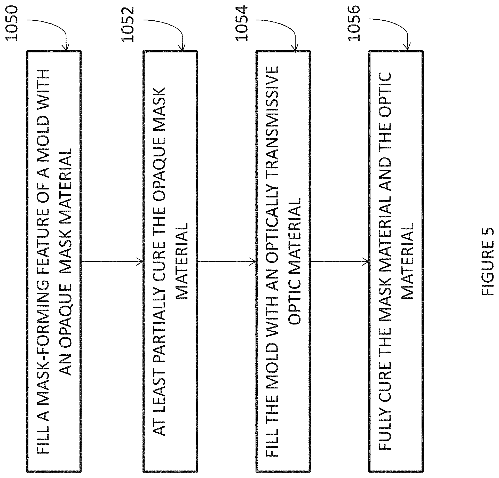
[0016] FIG. 5 is a flow chart of a method of manufacturing an intraocular lens with a mask positioned on a surface of the optic.
[0017] FIG. 6 is a flow chart of a method of manufacturing an intraocular lens with a mask embedded in the optic.
[0018] FIG. 7 is a flow chart of another method of manufacturing an intraocular lens within a mask embedded in the optic.
[0019] FIGS. 8A-8E illustrate different embodiments of a mold delineator.
[0020] FIGS. 9A-9F illustrate a method of manufacturing an intraocular lens using the steps shown in FIG. 7.
DETAILED DESCRIPTION
[0021] Patients who undergo intraocular lens (IOL) implantation surgery may still suffer from defects in their non-distance eyesight (e.g., presbyopia). One technique for treating such defects is by including an annular mask within or on the optic that increases the patient's depth of focus. The light rays that pass through the aperture in the mask converge at a focal point on the retina, while the light rays that would not converge at the focal point on the retina are blocked by an opaque portion of the mask configured to prevent at least some or substantially all visible light from being transmitted through the mask.
Mask
[0022] FIG. 1A illustrates a mask 2034a having an annular region 2036a surrounding an aperture 2038a substantially centrally located on the mask 2034a. An anterior surface of the annular region 2036a can have a curvature from the outer periphery to the inner periphery of the annular region 2036a, and the posterior surface of the annular region 2036a can have a similar curvature. However, as shown in FIG. 1B, the mask 2034b can also be flat. The mask 2034b can include an annular region 2034b surrounding an aperture 2038b substantially centered on the optical axis 2039b of the mask 2034b. Although the features described below are described with respect to the mask 2034a, one or the more of the features may be applied to the mask 2034b.
[0023] In some embodiments, the outer periphery of the mask 2034a is generally circular with an outer diameter of at least about 3 mm and less than about 6 mm. In some embodiments, the diameter of the outer periphery of the mask 2034a is at least about 3 mm and less than or equal to about 4 mm.
[0024] A thickness of the mask 2034a can be constant or can vary between the inner periphery (near the aperture) and the outer periphery. For example, the thickness may increase from an outer periphery and/or inner periphery of the mask 2034a and toward a radial midline of the annular region 2036a. In general, the thickness at any location of the mask 2034a can be less than or equal to about 200 microns, or less than or equal to about 100 microns, but preferably between about 1 micron and about 20 microns. For example, the thickness of the mask 2034a can be within the range: from about 1 micron to about 40 microns, from about 5 microns to about 20 microns, from about 5 microns to about 15 microns. In some implementations, the thickness of the mask 2034a can be within about two microns of: about 15 microns, about 10 microns, about 8 microns, or about 5 microns.
[0025] The aperture 2038a can transmit substantially all incident visible light along the optical axis 2039a. For example, the aperture 2038a can be a through-hole in the annular region 2036a or a substantially light transmissive (e.g., transparent to visible light) portion thereof. The aperture 2038a can be substantially circular and/or substantially centered around the optical axis 2039a of the mask 2034a. The size of the aperture 2038a can be any size that is effective to increase the depth of focus of an eye of a patient with presbyopia. In particular, the size of the aperture 2038a can be dependent on the location of the mask within the eye (e.g., distance from the retina). In some implementations, the aperture 2038a can have a diameter of at least about 0.85 mm and less than or equal to about 2.2 mm, at least about 1.1 mm and less than or equal to about 1.6 mm, or at least about 1.3 mm and less than or equal to about 1.4 mm.
[0026] The annular region 2036a can prevent transmission of substantially all or at least a portion of the spectrum of the incident visible light (e.g., radiant energy in the electromagnetic spectrum that is visible to the human eye) and/or the spectrum of non-visible light (e.g., radiant energy outside the range visible to humans). Preventing transmission of visible light through the annular region 2036a can block light that would not converge at the retina and fovea to form a sharp image. In some implementations, the annular region 2036a can prevent transmission of at least about: 90 percent of incident visible light, 92 percent of incident visible light, 95 percent of incident visible light, 98 percent of all incident visible light, or 99 percent of all incident visible light. In other words, the annular region 2036a can transmit no more than about: 10 percent of incident visible light, 8 percent of incident visible light, 5 percent of incident visible light, 3 percent of incident visible light, 2 percent of incident visible light, or 1 percent of incident visible light.
[0027] In some embodiments, opacity of the annular region 2036a is achieved because the material used to make mask 2034a is naturally opaque. In other embodiments, the material used to make the mask 2034a may be naturally substantially clear but treated with a dye or other pigmentation agent (e.g., carbon black).
[0028] Further variations of masks can be found in U.S. Pat. No. 7,628,810, filed May 26, 2004, U.S. Publication No. 2012/0143325, filed Feb. 19, 2012, U.S. Publication No. 2011/0040376, filed Aug. 13, 2010; U.S. Publication No. 2013/0268071, filed Nov. 30, 2012; U.S. Publication No. 2014/0264981; U.S. Publication No. 2015/0073549, filed Aug. 7, 2014; U.S. Pat. No. 5,662,706, filed Jun. 14, 1996 U.S. Pat. No. 5,905,561, filed Jun. 14, 1996; and U.S. Pat. No. 5,965,330, filed Dec. 6, 1996, all of which are included in the Appendix.
Intraocular Lens
[0029] As shown in FIGS. 2A-2D, the intraocular lens 1000 includes an optic 1004 and a mask 1012. The optic 1004 can be formed from an optically transmissive material, while the mask can be formed from an opaque material.
[0030] The optic 1004 may be monofocal or multifocal and it can have positive or negative optical power. The optic 1004 may be aspheric or any other configuration as the context may dictate. In some implementations, the greatest thickness of the optic 1004 is at the center of the optic 1004. In other implementations, the optic 1004 may have a reduced thickness at its center, which is further described in U.S. Publication No. 2011/0040376, filed Aug. 13, 2010, and is included in the Appendix. The optic 1004 may be substantially circular with an outer diameter between about 5.0 mm and about 8.0 mm, such as about 6.0 mm. A central thickness of the optic 1004 can be less than or equal to about 1.0 mm, such as between about 0.75 mm and about 1.0 mm.
[0031] The intraocular lens 1000 may include one or more haptics 1008 (e.g., one, two, three, four, or more) to prevent the intraocular lens 1000 from moving or rotating within the eye. As used herein the term "haptic" is intended to be a broad term encompassing struts and other mechanical structures that can be opposed against an inner surface of an eye and mounted to an optic to securely position an intraocular lens in an optical path of an eye. The haptics 1008 can be a variety of shapes and sizes depending on the location the intraocular lens 1000 is implanted in the eye. The haptics 1008 may be C-shaped, J-shaped, plate design, or any other design. The haptics 1008 may be manufactured substantially flat or vaulted with respect to the optic. Variations on the shape of the optic and the haptics can be found in U.S. Publication No. 2011/0040376, filed Aug. 13, 2010, which is included in the Appendix.
[0032] The mask 1012 can be formed on an anterior surface 1016 of the optic 1004 (see FIGS. 2A-2D), on a posterior surface 1020 of the optic 1004 (see FIGS. 3A-3D), or embedded within the optic 1004 (see FIGS. 4A-4D). When the mask 1012 is embedded within the optic 1004, the mask 1012 can be formed substantially at the midway line between the posterior 1020 and anterior surfaces 1016 of the optic 1004. But the mask 1012 can also be formed at other locations within the optic 1004.
Methods of Manufacturing
[0033] In some embodiments, the optic 1004 can be formed by molding a liquid lens material, such as an acrylic or silicone material, and curing the material into a solid. A completed solid mask 1012 can be pre-manufactured (e.g., from a different material than the optic) and positioned on or in the optic as part of this molding process. However, in this type of process where the mask 1012 is pre-manufactured and then molded into the optic, there is a potential for an inadequate bond between the mask and the optic. In addition, if the mask and the optic are made of different materials, there is a potential that the optical performance of the intraocular lens can be compromised due to the mask and optic materials potentially having elasticities and/or thermal expansion properties, which are too dissimilar. For example, if the material properties of the optic 1004 and the mask 1012 are not adequately compatible, then deformations, such as those resulting from injection forces during surgical implantation or swelling that may occur during manufacture due to chemical extractions, may damage the intraocular lens. Similarly, temperature shifts that occur during manufacture and/or surgical implantation can also damage the intraocular lens.
[0034] It can therefore be advantageous to manufacture the intraocular lens using a process where the mask is molded from the same material as the optic (e.g., a liquid acrylic or silicone material) at the same general time and/or such that the mask and optic undergo similar curing sequences (e.g., the mask and optic can be at least partially cured together). For example, the mask can be formed from a liquid material that has been modified to be substantially opaque by mixing in a dark pigment dye or dark particles, whereas the optic can be formed from the unmodified transparent liquid material. In this type of manufacturing process, however, mixing, bleeding, and/or blending can occur between the opaque mask material and the transparent optic material. If this occurs, the outer and inner diameter borders of the mask can become blurred and/or diffuse. This can negatively impact the optical performance of the intraocular lens.
[0035] This mixing, bleeding, and/or blending of the opaque and transparent liquid materials can be reduced or prevented by providing a mask-forming feature in the lens mold which can help prevent the opaque material from spreading beyond the desired region where the mask is to be formed on the surface of the optic or within the optic. In some embodiments, the mask-forming feature can be an annular trough formed in the lens mold at the location where the mask is to be positioned. This mask-forming trough can have inner and outer diameters, which correspond to the desired size of the mask. The opaque material used to form the mask can be added to fill this trough. Transparent material used to form the optic can be added over or around the opaque material in the mask-forming trough. The trough can help to prevent the opaque material from mixing, bleeding, and/or blending with the transparent material in a way that would blur the outer or inner diameter of the mask. The trough can achieve this, for example, through surface tension, which helps to hold the opaque material in place. In this way, more precise mask borders can be achieved. For example, the inner border line of the mask (which defines the central circular aperture 2038) and the outer border line of the mask (which defines the outer circular perimeter of the mask 2034) can each be circular to within 100 microns (e.g., any location along the inner or outer border of the mask can be within 100 microns of a perfect circle [or within 75 microns, or within 50 microns, or within 25 microns]). In addition, the outer border and the inner border can be concentric to within .+-.200 microns (e.g., the outer border and the inner border at any given angular position can be within 200 microns of being perfectly concentric [or within 150 microns, or within 100 microns, or within 50 microns]).
[0036] When forming an intraocular lens with the mask positioned on an anterior or posterior surface of the optic, a lens forming surface of the lens mold can include a mask-forming feature located at a position where the mask is to be formed. The mask-forming feature can be generally annular and defined by an outer edge and an inner edge. These edges can be sharp knife edges in order to more effectively hold the opaque mask material in place via surface tension. The lens forming surface can also include an optic region positioned radially inward and/or outward of the mask-forming feature. As just mentioned, the mask-forming feature can be an annular trough. This trough can be etched, machined, or otherwise cut into the lens forming surface of the lens mold. The trough can have a minimum depth that creates a mask thickness which provides less than 5% light transmission (or less than 3% or less than 2%). In some embodiments, the depth of the trough can be at least about 4 microns, or between about 5 microns and about 10 microns. But the trough can be as deep as practically appropriate without causing dissimilar material property interactions between the mask material and the optic material, resulting in poor injection performance (e.g., a maximum trough depth of about 150 microns).
[0037] The optic region of the lens forming surface of the mold will generally be curved in order to provide the intraocular lens with refractive optical power. In such embodiments, the mask-forming feature can have a different radius of curvature than the optic region. This difference in radius of curvature can result in a trough in the lens forming surface to create the mask-forming feature and facilitate the creation of a precise border between the mask and the optic. The radius of curvature of the mask-forming feature can be between about 25% and about 50% of the radius of the optic region, such as between about 25% and 35%, between about 30% and about 40%, between about 35% and about 45%, between about 40% and about 50%, or otherwise. In some implementations, the radius of curvature of the mask-forming feature can be between about 30% and about 35% of the radius of the optic region, such as about 32%. In other embodiments, however, the mask-forming feature and the optic region can have the same radius of curvature, but can be separated by a stepped transition.
[0038] FIG. 5 is a flow chart illustrating a method of manufacturing an intraocular lens with a mask positioned on the anterior or posterior side of the optic. The method can include preparing a mixture of uncured mask material (e.g., an acrylic copolymer or silicone) mixed or impregnated with a high density of carbon black particles or other black dye or pigments as needed to provide opaque properties (e.g., to permit no more than about 2% light transmission). A specific and precise volume of uncured opaque mask material can be dispensed (e.g., with a cannula) to fill the mask-forming feature and define an outer diameter and an inner diameter of the mask (block 1050). By relying on surface tension and capillary action of the viscous mask material, the dispensed volume can be specifically controlled to conform to the outer and inner edges of the mask-forming feature of the mold. The exposed surface of the uncured mask material (i.e., opposite the lens forming surface) can exhibit a curvature. To achieve these results, the mask material can have a viscosity and/or surface tension that can range from approximately that of water to acetic acid per as specified below:
TABLE-US-00001 Absolute Viscosity Surface Tension Fluid (N s/m.sup.2, Pa s) (cp) (10.sup.4 lb.sub.m/ft sec) mN/m Acetic acid 0.0011550 1.155 7.760 27.60 @ 20 C Water 0.0008900 0.890 6.000 71.95 @ 25 C
[0039] After filling the mask-forming feature, the mask can optionally be partially or fully cured using, for example, a combination of UV light and heat cycles (block 1052). Thereafter, the mold can be filled with an optically transmissive optic material, which may be the same as the mask material (e.g., acrylic or silicone), to over-mold the mask (block 1054). Finally, the mask material and the optic material can be fully cured-again, using a combination of UV light and heat cycles (block 1056).
[0040] In an alternative embodiment, the intraocular lens may be manufactured with the mask embedded within the optic. The method can include at least partially filling a first mold portion with an uncured optic material (block 1060). The first mold portion can be filled up to the depth where the mask is to be formed in the interior of the optic. In this way, the optic is initially only partially formed just to the thickness where the mask will be embedded in the completed optic. In this case, the first mold portion need not include a mask-forming feature. Instead, a second mold portion, which mates with the first mold portion, can include a structure that is the physical complement of the desired mask-forming feature. For example, the second mold portion can include an annular projection located where the mask is to be formed. The annular projection will form a trough in the partially-formed optic. As discussed further below, after at least partial curing of the optic material in the first mold portion, this trough in the partially-formed optic becomes the mask-forming feature and can be filled with opaque mask material.
[0041] After the first and second mold portions are mated together, the uncured transparent optic material can be partially or fully cured to form a trough in the interior surface of the partial optic (block 1062). The trough in the partial optic can be filled with an opaque mask material (block 1064). The opaque mask material can be prepared, for example, by mixing or impregnating an optically transmissive mask material (e.g., an acrylic copolymer or silicone) with a high density of carbon black particles or other black dye or pigments as needed to provide opaque properties (e.g., to permit no more than about 2% light transmission). A specific and precise volume of uncured opaque mask material can be dispensed (e.g., with a cannula) to exactly fill the trough in the partial optic and define an outer diameter and an inner diameter of the annular mask. By relying on surface tension and capillary action of the viscous mask material, the dispensed volume can be specifically controlled to conform to the outer and inner edges of the trough in the partial optic. The exposed surface of the uncured mask material (i.e., opposite interior surface of the optic) can exhibit a curvature. After filling the trough in the partial optic, the mask can optionally be partially or fully cured (block 1066). Thereafter, the mold can be filled with additional optic material to over-mold the mask (block 1068). A third mold portion can be used in place of the second mold portion to form an outer surface of the optic. Finally, the mask material and the optic material can be fully cured (block 1070). In some implementations, one of the mold portions may include a protruding pin that defines the inner diameter of the mask-forming feature and radially centers the mask in the optic.
[0042] An alternative method of manufacturing an intraocular lens with an embedded mask is illustrated in FIG. 7 and FIGS. 9A-9F. A measured partial volume of liquid type uncured optic material 2060 can be placed in a mold half 2062a (block 1080 and FIG. 9A). An edge border delineator 2050 can be placed on the center of the liquid optic material 2060 (block 1082 and FIG. 9B). A bead of opaque mask material 2064 can be dispensed within the lines of the edge border delineator 2050 (block 1084). The opaque mask material 2064 wicks to the confinements of the edge border delineator 2050 (FIG. 9C). Optionally, a bead of uncured optic material 2060 can be dispensed within the central aperture of the edge border delineator 2050 (FIG. 9D). The bead of optic material 2060 wicks to the inner periphery of the edge border delineator. At least the surface of the optic material 2060 can be partially cured at this time (block 1086). A measured partial volume of uncured optic material 2060 can be placed into the opposite mold half 2062b (block 1088). The two mold halves 2062a, 2062b can then be joined together and the intraocular lens can be put through the full curing process (block 1090 and FIG. 9E). Thereafter, the intraocular lens can be removed from the mold (FIG. 9F).
[0043] FIG. 8A illustrates an embodiment of the edge border delineator 2050. The edge border delineator 2050 can include an outer border 2052 spaced apart from an inner border 2054. As explained above, the opaque mask material can be dispensed between the outer border 2052 and the inner border 2054. The bead of optic material can be dispensed radially inward of the inner border 2054. The edge border delineator 2050 can be made from compatible polymer or elastic type polymer material (e.g., an acrylic copolymer or silicone). A width of the inner and/or outer border 2054, 2052 (e.g., in a radial direction) can be within a range of 100 microns to 500 microns. The thickness of the inner and/or outer border 2054, 2052 (e.g., in an anterior-posterior direction) can be between about 5 and 15 microns thick with a flat formed shape. Connecting spokes 2056 may or may not be used to maintain inner and outer border concentricity (see FIG. 8B). The cross-sectional profile of the inner and/or outer border 2054, 2052 can be vertical, stair stepped (see FIG. 8C), sloped (see FIG. 8D), fully contained (see FIG. 8E), or any other profile to facilitate the wicking/capillary action of the liquid acrylic as necessary. A plurality of mechanical locking holes can be provided in the edge border delineator to support capillary action and to minimize delamination of the intraocular during injection.
Terminology
[0044] Conditional language, such as "can," "could," "might," or "may," unless specifically stated otherwise, or otherwise understood within the context as used, is generally intended to convey that certain embodiments include, while other embodiments do not include, certain features, elements, and/or steps. Thus, such conditional language is not generally intended to imply that features, elements, and/or steps are in any way required for one or more embodiments or that one or more embodiments necessarily include logic for deciding, with or without user input or prompting, whether these features, elements, and/or steps are included or are to be performed in any particular embodiment.
[0045] The terms "comprising," "including," "having," and the like are synonymous and are used inclusively, in an open-ended fashion, and do not exclude additional elements, features, acts, operations, and so forth. Also, the term "or" is used in its inclusive sense (and not in its exclusive sense) so that when used, for example, to connect a list of elements, the term "or" means one, some, or all of the elements in the list.
[0046] The terms "approximately." "about," and "substantially" as used herein represent an amount close to the stated amount that still performs a desired function or achieves a desired result. For example, the terms "approximately," "about," and "substantially" may refer to an amount that is within less than 10% of the stated amount, as the context may dictate.
[0047] The ranges disclosed herein also encompass any and all overlap, sub-ranges, and combinations thereof. Language such as "up to," "at least," "greater than," "less than," "between" and the like includes the number recited. Numbers preceded by a term such as "about" or "approximately" include the recited numbers. For example, "about 3 mm" includes "3 mm."
[0048] Although certain embodiments and examples have been described herein, it will be understood by those skilled in the art that many aspects of the methods and IOLs shown and described in the present disclosure may be differently combined and/or modified to form still further embodiments or acceptable examples. All such modifications and variations are intended to be included herein within the scope of this disclosure. A wide variety of designs and approaches are possible. No feature, structure, or step disclosed herein is essential or indispensable.
[0049] For purposes of this disclosure, certain aspects, advantages, and novel features are described herein. It is to be understood that not necessarily all such advantages may be achieved in accordance with any particular embodiment. Thus, for example, those skilled in the art will recognize that the disclosure may be embodied or carried out in a manner that achieves one advantage or a group of advantages as taught herein without necessarily achieving other advantages as may be taught or suggested herein.
[0050] Moreover, while illustrative embodiments have been described herein, the scope of any and all embodiments having equivalent elements, modifications, omissions, combinations (e.g., of aspects across various embodiments), adaptations and/or alterations as would be appreciated by those in the art based on the present disclosure. The limitations in the claims are to be interpreted broadly based on the language employed in the claims and not limited to the examples described in the present specification or during the prosecution of the application, which examples are to be construed as non-exclusive. Further, the actions of the disclosed processes and methods may be modified in any manner, including by reordering actions and/or inserting additional actions and/or deleting actions. It is intended, therefore, that the specification and examples be considered as illustrative only, with a true scope and spirit being indicated by the claims and their full scope of equivalents.
* * * * *
D00000
D00001
D00002
D00003
D00004
D00005
D00006
D00007
D00008
D00009
D00010
D00011
D00012

D00013

D00014

XML
uspto.report is an independent third-party trademark research tool that is not affiliated, endorsed, or sponsored by the United States Patent and Trademark Office (USPTO) or any other governmental organization. The information provided by uspto.report is based on publicly available data at the time of writing and is intended for informational purposes only.
While we strive to provide accurate and up-to-date information, we do not guarantee the accuracy, completeness, reliability, or suitability of the information displayed on this site. The use of this site is at your own risk. Any reliance you place on such information is therefore strictly at your own risk.
All official trademark data, including owner information, should be verified by visiting the official USPTO website at www.uspto.gov. This site is not intended to replace professional legal advice and should not be used as a substitute for consulting with a legal professional who is knowledgeable about trademark law.