Cosmetic Container
Hori; Yumiko
U.S. patent application number 16/856024 was filed with the patent office on 2020-10-29 for cosmetic container. This patent application is currently assigned to YOSHIDA INDUSTRIES CO., LTD.. The applicant listed for this patent is YOSHIDA INDUSTRIES CO., LTD.. Invention is credited to Yumiko Hori.
| Application Number | 20200337435 16/856024 |
| Document ID | / |
| Family ID | 1000004783632 |
| Filed Date | 2020-10-29 |


| United States Patent Application | 20200337435 |
| Kind Code | A1 |
| Hori; Yumiko | October 29, 2020 |
COSMETIC CONTAINER
Abstract
A cosmetic container that is suitable for being made compact and that does not leak when inverted, even when low-viscosity cosmetics are contained therein, and which allows the cosmetics to be reliably oozed when used. The cosmetic container includes a container body for containing a liquid cosmetic, the container body having an upwardly open opening therein, an outer lid for sealing the opening in the container body and a plate-shaped pad that vertically partitions the interior of the container body. The pad is made of felt. The maximum amount of the cosmetic in the container body is such that, when the container body is upright so that the opening in the container body faces vertically upward, the liquid level of the cosmetic is below the bottom surface of the pad.
| Inventors: | Hori; Yumiko; (Tokyo, JP) | ||||||||||
| Applicant: |
|
||||||||||
|---|---|---|---|---|---|---|---|---|---|---|---|
| Assignee: | YOSHIDA INDUSTRIES CO.,
LTD. Tokyo JP |
||||||||||
| Family ID: | 1000004783632 | ||||||||||
| Appl. No.: | 16/856024 | ||||||||||
| Filed: | April 23, 2020 |
| Current U.S. Class: | 1/1 |
| Current CPC Class: | A45D 34/04 20130101; A45D 2200/1018 20130101; A45D 40/26 20130101; A45D 2200/05 20130101; A45D 40/0068 20130101 |
| International Class: | A45D 34/04 20060101 A45D034/04; A45D 40/00 20060101 A45D040/00; A45D 40/26 20060101 A45D040/26 |
Foreign Application Data
| Date | Code | Application Number |
|---|---|---|
| Apr 26, 2019 | JP | 2019-085949 |
Claims
1. A cosmetic container, comprising: a container body for containing a liquid cosmetic, the container body having an upwardly open opening therein; an outer lid for sealing the opening in the container body; and a plate-shaped pad that vertically partitions an interior of the container body, wherein the pad is made of felt.
2. The cosmetic container according to claim 1, wherein a maximum amount of the cosmetic in the container body is an amount such that a surface of the liquid cosmetic contained in the container body is below a bottom surface of the pad in a state in which the container body is upright, so that the opening in the container body is directed vertically upward.
3. The cosmetic container according to claim 2, wherein a mark indicating a position of the surface of the liquid cosmetic corresponding to the maximum amount of the cosmetic is provided to the container body.
4. The cosmetic container according to claim 1, further comprising a pad moving mechanism that moves the pad returnably downward when the upper surface of the pad is pressed downward.
5. The cosmetic container according to claim 4, wherein the pad moving mechanism includes a movable frame configured to be slidable with respect to an inner surface of the container body and a fixed frame disposed above the movable frame, the movable frame includes a spring that is compressed between a bottom surface of the container body and a lower surface of a frame portion that holds a periphery of the pad, and the lower surface of the fixed frame contacts an upper surface of the movable frame when the spring is in the restored state to stop the movable frame at a predetermined vertical position.
6. The cosmetic container according to claim 5, wherein the spring is a leaf spring.
7. The cosmetic container according to claim 5, wherein the spring is a coil spring having a spiral axis extending in a vertical direction.
8. The cosmetic container according to claim 1, wherein the pad is made of plastic fibers thermally welded to each other along an outer periphery of the pad.
9. The cosmetic container according to claim 1, further comprising a frame body mounted on the container body and having an annular portion of double-ring construction, the two rings facing each other in a vertical direction, wherein the pad is disposed between the two rings of the annular portion, and a cut-out for inserting the pad between the rings is formed in at least one of the rings of the double-ring structure.
10. The cosmetic container according to claim 1, further comprising a frame attached to the container body and having an annular frame formed thereon, and the periphery of the pad is welded to the frame.
11. The cosmetic container according to claim 1, wherein the pad has a thickness of at least 1 mm but not more than 3 mm, and a porosity of at least 70% but not more than 90% as determined by a WET (v/v) method, and the viscosity of the cosmetic stored in the container body is at least 1 cs but not more than 1000 cs.
Description
CROSS-REFERENCE TO RELATED APPLICATIONS
[0001] This application claims priority pursuant to 35 U.S.C. .sctn. 119 from Japanese Patent Application No. 2019-085949, filed on Apr. 26, 2019, the content of which is incorporated herein by reference in its entirety.
BACKGROUND
Technical Field
[0002] The present invention relates to cosmetic container, in particular, a cosmetic container for storing a cosmetic made of a low-viscosity fluid.
Related Art
[0003] Some cosmetics are applied using a puff or a finger. As a cosmetic container for accommodating this type of cosmetic, there is that which includes a bottomed container body that can be hermetically sealed by an outer lid, and an inner lid in which a screen made of a mesh material is disposed. By pushing the screen toward the bottom of the container body the cosmetic is exuded onto the surface of the screen. For example, if one holds down the screen with a puff, the cosmetic is transferred to a puff. The user then takes up the exuded cosmetic with the puff or with the fingers.
[0004] In addition, in a cosmetic container that stores cosmetics designed to be applied using a puff, the puff is often stored in a space between the screen and the lid in the container body.
SUMMARY OF THE INVENTION
Problem to be Solved by the Invention
[0005] Cosmetic containers for storing cosmetics to be applied using puffs or fingers are required to ensure that the cosmetic contained therein does not leak out when the container is inverted and that the cosmetic can be reliably oozed.
[0006] However, some cosmetics such as lotions have a very low viscosity (e.g., 1000 cs or less) and are almost liquid. As a result, when a low-viscosity cosmetic is contained in a cosmetic container with an inner lid in which a screen is disposed as described in JP 2016-220871A, when the cosmetic container is inverted, the cosmetic leaks through the mesh of the screen.
[0007] In addition, when puffing a low-viscosity cosmetic, the cosmetic readily passes through the mesh of the screen and it is difficult to obtain an appropriate amount. For this reason, cosmetics having a low viscosity have conventionally often been stored in bottles and the like. That is, in the case of using cosmetics having a low viscosity in a puff, a container for storing the puff is required besides the bottle for the cosmetic itself.
[0008] JP 2017-2026A describes an impregnated material for impregnating a cosmetic having a viscosity of about 1,000 to 7000 cs. Therefore, it is conceivable to provide a low-viscosity cosmetic impregnated into an impregnated material such as a sponge. However, in this case, it is not possible to replace only the cosmetic and it therefore becomes difficult to provide the cosmetic at a lower cost. Moreover, even if the replenished cosmetic is provided in a state of being impregnated into the impregnated material, a long time is required to impregnate the impregnated material with the cosmetic, and it becomes difficult to provide the replenished cosmetic at reduced cost.
[0009] Conceivably, the user could replenish or refill a cosmetic container that has been emptied or nearly emptied. But this refilling imposes a burden on the user to impregnate the cosmetic, and the cosmetics cannot be replenished or refilled quickly or easily. Of course, in a case in which the cosmetic is provided in a state of being impregnated into the impregnated material, an impregnated material capable of impregnating the entire amount of the cosmetic is required in addition to the cosmetic. That is, the volume of the impregnated material increases, and the size of the cosmetic container in which the impregnated material is contained also increases as a result. As the size of the cosmetic container increases, the portability of the cosmetic container decreases. On the other hand, if the cosmetic container is made smaller, the user can then carry only a small amount of cosmetic.
[0010] Furthermore, the impregnated material described in JP 2017-2026A assumes that it will be impregnated with a cosmetic having a viscosity greater than 1000 cs. Accordingly, if impregnated with a cosmetic having a lower viscosity, then, like the mesh material, the cosmetic may drip from the impregnated material when the container is inverted.
[0011] It is an object of the present invention to provide a cosmetic container that is suitable for being made compact, which does not leak when inverted when containing cosmetics of low viscosity, and enables the cosmetic to be oozed reliably when in use.
Solution to the Problem
[0012] To achieve the above-described object, the present invention provides a cosmetic container including a container body for containing a liquid cosmetic, the container body having an upwardly open opening therein, an outer lid for sealing the opening in the container body, and a plate-shaped pad that vertically partitions the interior of the container body. The pad is made of felt.
[0013] A maximum amount of the cosmetic in the container body may be an amount such that a surface of the liquid cosmetic contained in the container body is below a bottom surface of the pad in a state in which the container body is upright, so that the opening in the container body is directed vertically upward. Moreover, a mark indicating a position of the surface of the liquid cosmetic corresponding to the maximum amount of the cosmetic may be provided to the container body.
[0014] The cosmetic container may be provided with a pad moving mechanism that moves the pad returnably downward when the upper surface of the pad is pressed downward.
[0015] The pad moving mechanism may include a movable frame configured to be slidable with respect to an inner surface of the container body and a fixed frame disposed above the movable frame. The movable frame includes a spring that is compressed between a bottom surface of the container body and a lower surface of a frame portion that holds a periphery of the pad, and the lower surface of the fixed frame contacts an upper surface of the movable frame when the spring is in the restored state to stop the movable frame at a predetermined vertical position. The spring may be a leaf spring, or a coil spring having a spiral axis extending in a vertical direction.
[0016] The pad may be made of plastic fibers thermally welded to each other along an outer periphery of the pad. The cosmetic container may further include a frame body mounted on the container body and having an annular portion of double-ring construction, the two rings facing each other in a vertical direction, wherein the pad is disposed between the two rings of the annular portion, and a cut-out for inserting the pad between the rings is formed in at least one of the rings of the double-ring structure. Alternatively, the cosmetic container may further include a frame attached to the container body and having an annular frame formed thereon, with the periphery of the pad welded to the frame.
[0017] The pad has a thickness of at least 1 mm but not more than 3 mm, and a porosity of at least 70% but not more than 90% as determined by a WET (v/v) method.
[0018] Preferably, the viscosity of the cosmetic stored in the container body is at least 1 cs but not more than 1000 cs.
Effects of the Invention
[0019] The present invention provides a cosmetic container that is suitable for being made compact and which does not leak when inverted when containing cosmetics of low viscosity, and enables the cosmetic to be oozed reliably when in use.
[0020] Other advantages and effects of the present invention will become apparent from the following description.
BRIEF DESCRIPTION OF THE DRAWINGS
[0021] FIG. 1 is an exploded perspective view of a cosmetic container according to an embodiment of the present invention.
[0022] FIGS. 2A-2C are drawings illustrating an assembled state and a structure of the cosmetic container according to the embodiment.
[0023] FIG. 3A-3B are drawings illustrating a frame constituting an inner lid included in the cosmetic container according to the embodiment.
[0024] FIG. 4A-4B are drawings illustrating a variation of the inner lid.
[0025] FIG. 5A-5C are drawings illustrating injection molding of the inner lid according to a variation.
[0026] FIG. 6A-6B are drawings illustrating a cosmetic container according to another embodiment of the present invention.
[0027] FIG. 7A-7B are drawings illustrating a cosmetic container according to another embodiment of the present invention.
DETAILED DESCRIPTION
[0028] Embodiments of the present invention are described below with reference to the accompanying drawings. In the drawings referenced in the following description, the same or similar parts may be denoted by the same reference numerals and redundant description omitted. In some drawings, reference numerals from other drawings may be omitted for simplicity.
[0029] Cosmetic Container
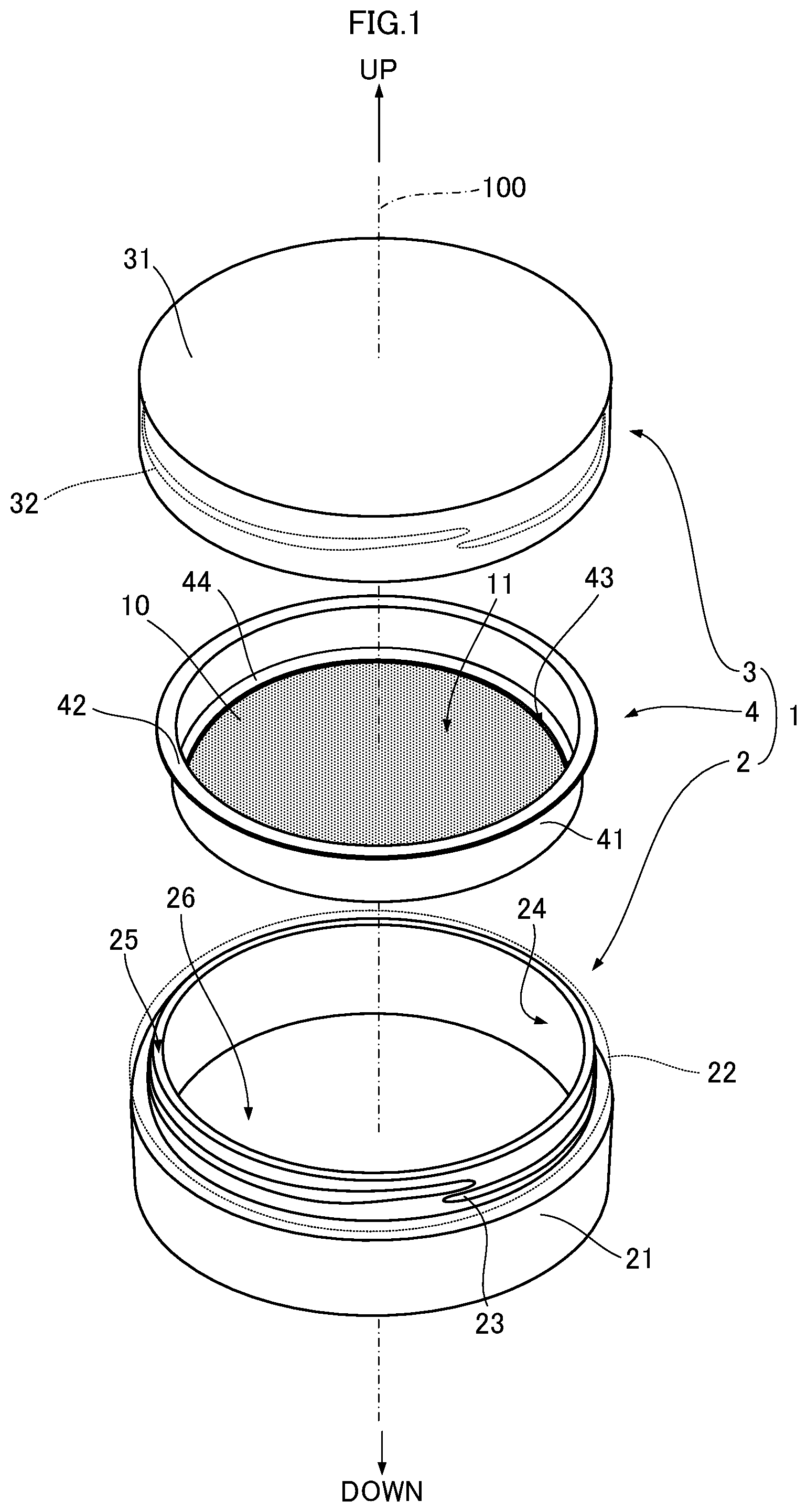
[0030] Given here as an embodiment of the present invention is a cosmetic container containing cosmetic consisting of a liquid with a very low viscosity (e.g., 1 to 1000 cs), and which can be used by transferring the cosmetic to a puff. FIG. 1 is a perspective view of the cosmetic container 1 according to the embodiment, disassembled into its constituent components. As illustrated in FIG. 1, the cosmetic container 1 has a bottomed, stepped cylindrical container body 2, an outer lid 3 that seals an opening in the container body 2, and an inner lid 4 that is detachably mounted on the container body 2. Here, the direction in which the cylindrical axis 100 of the stepped cylindrical container body 2 extends is defined as the vertical direction, and the respective up and down directions are relatively defined assuming that the bottom of the container body 2 is at the bottom. In addition, the vertical direction of the outer lid 3 and the inner lid 4 and the position where the cylindrical axis 100 penetrates are defined based on the state of being mounted on the container body 2. That is, even if the outer lid 3 and the inner lid 4 are taken out of the container body 2, the vertical direction and the penetrating position of the cylindrical axis 100 are unchanged. The structure of the container body 2, the outer lid 3, and the inner lid 4, which together constitute the cosmetic container, are described below.
[0031] The container body 2 has a stepped cylindrical external shape while at the same time maintaining a constant inner diameter from the upper end 25 to the inside of the bottom (hereinafter, a bottom surface 26), such that there are no steps on the inner surface 24 of the container body 2. That is, the container body 2 consists of a lower region that is formed thick and an upper region that is thinned. The thickened lower region is used as a cosmetic container portion 21, and a coaxial cylindrical neck portion 22 thinned with respect to the container portion 21 is formed as a single unit with and above the container portion 21. A male screw is 23 is formed on the outer periphery of the neck portion 22.
[0032] The outer lid 3 has a flat bottomed cylindrical shape with the top part as the bottom (hereinafter referred to as the top part 31). On the inner surface of the outer lid 3, a female screw 32 that engages the male screw 23 of the neck portion 22 is formed. The inner lid 4 is composed of a vertically flattened cylindrical frame 41 having a bottom and a flange 42 at the upper end, and a disc-shaped pad 10 made of felt disposed at the lower end side of the frame 41. The frame 41 has a portion (hereinafter, a bottom 44) formed in an annular shape by a downwardly open opening 43. The pad 10 is mounted on the bottom 44 of the frame 41, and the upper surface 11 and the bottom surface of the pad 10 are exposed upward and downward, respectively, through the opening 43 in the bottom 44 of the frame 41.
[0033] As is well known, felt is not a woven fabric but a fabric obtained by compressing fibers into a thin plate shape. Felt is characterized in that the fibers are irregularly bonded, the strength and elongation have no directionality, and the thickness and the porosity (the ratio of the volume of the voids to the total volume) can be easily adjusted. In the cosmetic container 1 according to the embodiment, the container body 2, the outer lid 3, and the frame 41 are formed by plastic injection molding.
[0034] FIGS. 2A-2C illustrate the container body 2, the outer lid 3, and the inner lid 4 that constitute the cosmetic container 1, the detailed structure of the cosmetic container 1, and the state of containment of the cosmetic 5 in the container body 2. FIG. 2A illustrates a state in which the inner lid 4 is mounted in the container body 2 and FIG. 2B illustrates a state in which the outer lid 3 is mounted on the container body 2. FIG. 2C is a longitudinal sectional view of the cosmetic container 1 along a plane including the vertical direction.
[0035] As illustrated in FIG. 2A, when the inner lid 4 is mounted in the container body 2, the lower surface of the flange 42 of the inner lid 4 (indicated by reference numeral 46 in FIG. 2C) contacts the upper end of the container body 2 (reference numeral 25 in FIG. 2C). As a result, the inner lid 4 is prevented from falling into the container body 2. As a structure for preventing the inner lid 4 from falling into the container body 2, besides providing the flange 42 on the inner lid 4, for example, an appropriate structure, such as a protrusion for supporting the lower end of the inner lid 4, can be provided to the inner surface 24 of the container body 2. Then, once the inner lid 4 is mounted in the container body 2 and the outer lid 3 is mounted to the neck portion 22 of the container body 2, as illustrated in FIG. 2B, the cosmetic container 1 achieves a flat cylindrical appearance.
[0036] As described above, the frame 41 of the inner lid 4 is a vertically flattened cylinder, the lower end of which has the opening 43 therein and forms the bottom 44 that upwardly and downwardly exposes the upper surface 11 and the lower surface 12, respectively, of the pad 10. As illustrated in FIG. 2C, the cosmetic 5 is contained in the space between the lower surface 12 of the pad 10 and the bottom surface 26 of the container body 2 in the container portion 21 of the container body 2. The maximum amount of the cosmetic 5 stored in the container portion 21 of the container body 2 is such that, when the cosmetic container 1 is upright with the bottom surface 26 of the container body 2 facing down, a liquid level 51 of the cosmetic 5 is set so as not to contact the lower surface 12 of the pad 10. Note that, in the container body 2, the upper surface 11 side of the pad 10 serves as a puff storage location.
[0037] Packing 33 is installed inside the top part 31 of the outer lid 3. When the outer lid 3 is mounted on the container body 2 by the female screw 32 formed on the inner surface of the outer lid 3 and the male screw formed 23 on the neck portion 22 of the container body 2, the lower surface 34 of the packing 33 presses against the upper surface 45 of the flange 42 of the inner lid 4 and the lower surface 46 of the flange 42 presses against the upper end 25 of the container body 2, thereby sealing the container body 2 and preventing evaporation of the cosmetic 5.
[0038] The inner surface 24 of the container body 2 and the outer peripheral surface 47 of the frame 41 of the inner lid 4 press against each other, so when the cosmetic container 1 is inverted while the outer lid 3 is not sealed, the cosmetic 5 does not leak through the contact interfaces (24 and 47, 25 and 46) between the inner lid 4 and the container body 2.
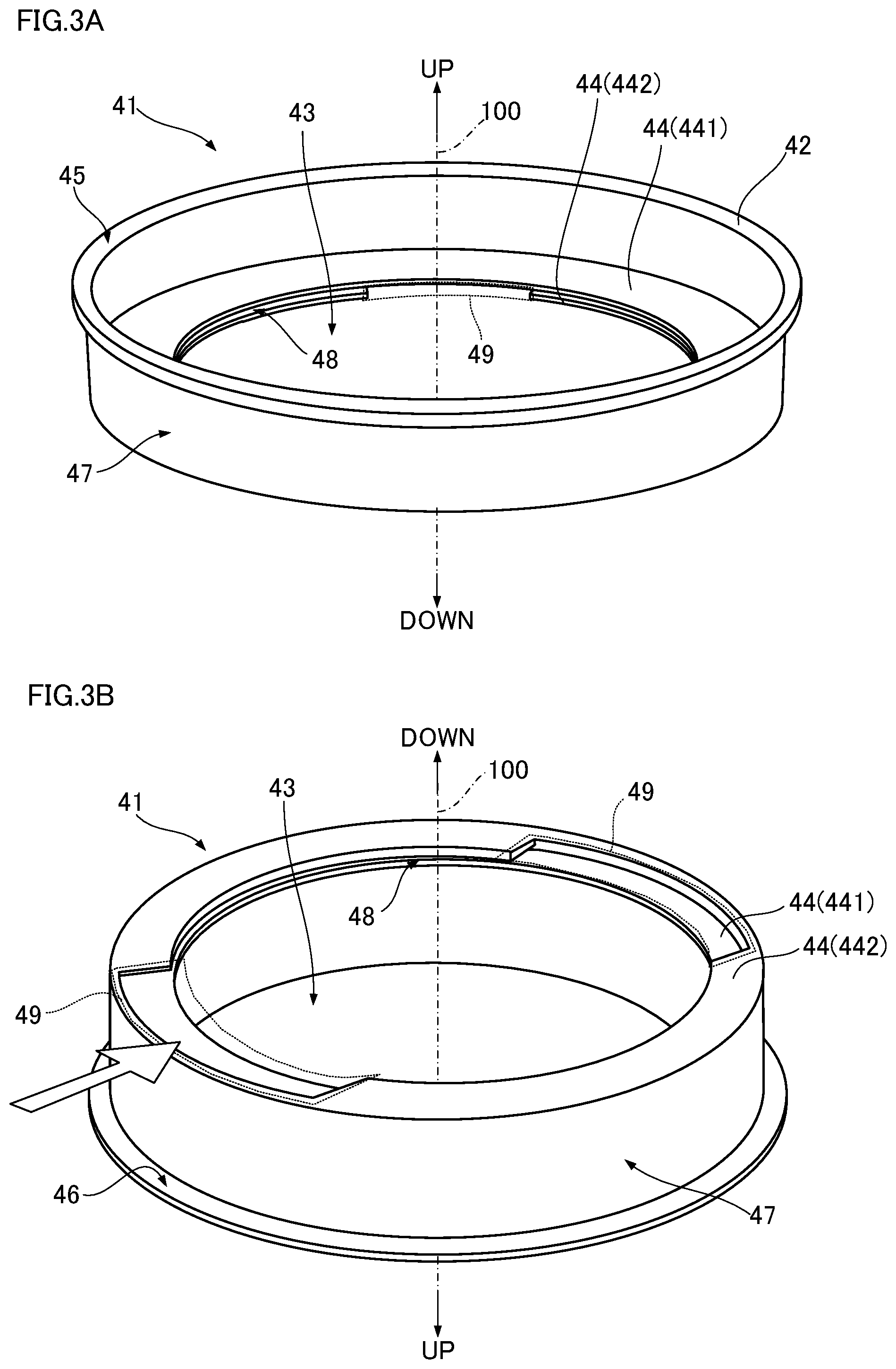
[0039] The frame 41 of the inner lid 4 has a structure for securely holding the pad 10, and leakage of the cosmetic 5 from the inner surface side of the frame 41 via the outer peripheral surface 13 of the pad 10 is also prevented. FIGS. 3A-3B illustrate the structure of the frame 41. FIG. 3A is a perspective view of the frame 41 from above, and FIG. 3B is a perspective view of the frame 41 from below. The holding structure for the pad 10 in the frame 41 is described in greater detail below with reference to FIG. 2C and FIGS. 3A-3B.
[0040] As described above, the frame 41 is a vertically flattened, bottomed hollow cylinder with a bottom 44 facing downward, with the opening 43 formed in the center of the bottom. As illustrated in FIGS. 2C and 3A-3B, the bottom 44 has a double-ring structure with two rings facing each other vertically across a gap 48. The pad 10 is disposed between the rings at the bottom 44 of the double-ring structure. As illustrated in FIG. 3A, an upper bottom portion 441 is formed in an annular shape, and a lower bottom portion 442 has cut-outs 49 formed by cutting out portions as illustrated in FIG. 3B. As a result, as illustrated in FIG. 2C, the bottom 44 has a C-shaped vertical cross-sectional shape in a region where the cut-outs 49 are not formed. In these regions where the vertical cross-sectional shape of the bottom 44 is C-shaped, the peripheral portion of the pad 10 between the upper surface 11 and the lower surface 12 of the pad 10 is held in a compressed state between the upper and lower bottom portions 441, 442.
[0041] It should be noted that, in the frame 41 of the cosmetic container 1 according to the embodiment, the cut-outs 49 are formed at two positions opposite each other and symmetrical about the cylindrical axis 100. The pad 10 is bent slightly when mounted in the frame 41 and may be slid into the gap 48 with the upper bottom portion 442 through the cut-out 49 in the lower bottom portion 442 of the frame as indicated by the blank arrow in FIG. 3B.
[0042] Amount of Cosmetic; Method of Taking Out Cosmetic
[0043] In the cosmetic container 1 of the embodiment having the above-described configuration, the pad 10 is made of felt. Unlike a screen made of a mesh material the pad 10 made of felt does not bend much, and if the load is smaller than the yield stress the surface is merely dented and compressed when pressed; if the load is released, the pad 10 returns to its original shape. In the cosmetic container 1 according to the embodiment, the porosity and the thickness of the pad 10 are set according to the viscosity of the cosmetic 5 contained in the container portion 21, so that the cosmetic 5 impregnated from the lower surface 12 of the pad 10 can be oozed from the upper surface 11 of the pad 10. Moreover, even if the cosmetic container 1 is inverted, the pad 10 remains impregnated with the cosmetic 5 and the cosmetic 5 does not leak from the upper surface 11 of the pad 10.
[0044] As a procedure for taking out the cosmetic 5 from the cosmetic container 1 according to the embodiment, first, the lower surface 12 of the pad 10 is brought into contact with the cosmetic 5 by inverting the cosmetic container 1 or the like. As a result, the cosmetic 5 is impregnated into the felt pad 10 by capillary action. Then, the upper surface 11 of the pad 10 is pressed downward with a puff or the like to compress the pad 10. As a result, the cosmetic 5 impregnated into the pad 10 oozes out onto the upper surface 11 side of the pad 10 and the cosmetic 5 is transferred to the puff.
[0045] Maximum Amount of Cosmetic
[0046] Note that in other instruments that use felt (such as felt-tip pens, alcohol lamps, etc.), one end of the rod-shaped wick made of felt is always in contact with the ink or alcohol fuel. As a result, the ink taken up into the wick by capillary action is transferred to the paper surface at the other end of the wick, or the alcohol fuel taken up by the wick volatilizes and burns at the other end of the wick. In contrast, in the cosmetic container 1 according to the embodiment, it is assumed that the pad 10 made of felt is not in contact with the cosmetic 5 except when the cosmetic 5 is being used, at which time the pad 10 is temporarily impregnated with the cosmetic 5. In the case of a felt pen or an alcohol lamp, if the ink or alcohol fuel is not continuously supplied to the wick, the ink may fade or the flame may be extinguished. However, with the cosmetic container 1, the pad only needs to be pre-impregnated with an amount of cosmetic sufficient for a single use. Further, the pad 10 has an extremely large area for taking up the liquid compared to the rod-shaped wick, so that the cosmetic 5 impregnated into the pad 10 is quickly evaporated. Therefore, if the cosmetic 5 is constantly in contact with the pad 10, the cosmetic 5 contained in the container portion 21 will evaporate while being impregnated into the pad 10, and there is a possibility that the amount of the cosmetic 5 will decrease even before use.
[0047] Therefore, when the cosmetic container 1 according to the embodiment is stood upright so that the opening in the container body 2 faces vertically upward, the liquid level 51 of the cosmetic 5 is below the lower surface 12 of the pad 10. That is, in the cosmetic container 1 according to the embodiment, the maximum amount of the cosmetic 5 in the container portion 21 is limited. In order to limit the amount of the cosmetic 5 in the container portion 21, conceivably a mark such as a scale may be provided to the inner surface 24 of the container portion 21 at the height of the liquid level 51 when the container portion 21 is filled with the maximum amount of cosmetic 5. Alternatively, the user may be made aware that the liquid level 51 of the cosmetic 5 is to remain below the lower surface 12 of the pad 10 when replenishing or replacing the cosmetic 5 by including a warning to that effect in the user manual or at some suitable place on the cosmetic container 1. Refills may be provided that are always in the maximum amount or less. In any case, it is sufficient that a predetermined amount or more of the cosmetic is not put into the container portion 21.
[0048] Porosity and Thickness of Pad
[0049] As described above, in the cosmetic container 1 according to the embodiment, the porosity and thickness of the pad 10 is set according to the viscosity of the cosmetic 5. As a result, the cosmetic 5 stored in the container portion 21 can be taken out from the upper surface 11 of the pad 10 while at the same time the cosmetic 5 in the container portion 21 does not leak from the upper surface 11 of the pad 10 even when the cosmetic container 1 is inverted. A method of setting the porosity and thickness of the pad 10 according to the viscosity of the cosmetic 5 is described below.
[0050] Cosmetic Taking-Out Performance
[0051] The essential function required of the cosmetic container 1 is to enable taking-out of the cosmetic 5 contained in the container portion 21 from the upper surface 11 of the pad 10. In order to evaluate the ease of taking out the cosmetic 5 (i.e., cosmetic taking-out performance) from the cosmetic container 1 according to the embodiment, multiple cosmetic containers 1 were prepared using various types of liquids having different viscosities and pads 10 having different porosities and thickness.
[0052] The porosity of the pad 10 is obtained from an equation according to a known WET (v/v) method. The WET (v/v) method can determine the porosity more accurately by taking into consideration differences in specific gravity according to differences in the material of the fiber constituting the pad 10. If A is the dry mass of the pad 10, B is the saturated water content of the pad 10, and p is the specific gravity of the fiber used for the pad 10, then the porosity WET (v/v) can be found by the following equation:
WET(v/v)=[(B-A)/{(A/.rho.)+(B-A)}].times.100(%).
Note that the pad 10 used for evaluating cosmetic taking-out performance is made of polyester (PET) and low-melting polyester (LPET).
[0053] The relation between viscosity and liquid taking-out performance of the liquid contained in the container portion 21 using cosmetic containers 1 of different types of pads 10 was examined. Specifically, first, the cosmetic container 1 was inverted for 1 minute with the liquid contained in the container portion 21 to impregnate the pad 10 with the liquid. Next, in a state in which the cosmetic container 1 was stood upright, a puff was pressed three times against the pad 10 to transfer the liquid to the puff and a cosmetic taking-out test was performed. The difference in mass of the puff before and after transferring the liquid represented the mass of the liquid transferred to the puff. The cosmetic taking-out test was performed three times for each combination of type of pad 10 and type of liquid used, and the average value of the mass of the liquid at each time was used as the test result.
[0054] TABLE 1 below shows the results of the cosmetic taking-out test.
TABLE-US-00001 TABLE 1 PAD LIQUID POROSITY WET THICKNESS SILICONE OIL (v/v)(%) (mm) WATER ETHANOL 1 cs 500 cs 1000 cs 70 1 0.204 0.688 0.508 0.178 0.085 2 0.269 0.671 0.493 0.086 0.042 3 0.206 0.679 0.510 -- -- 75 1 0.223 0.984 0.574 0.161 0.169 2 0.283 0.861 0.646 0.134 0.071 3 0.287 0.974 0.643 0.091 -- 80 1 0.204 1.028 0.895 0.182 0.257 2 0.264 1.034 1.009 0.223 0.071 3 0.301 0.897 1.089 0.191 -- 85 1 0.308 1.166 0.972 0.241 0.266 2 0.343 1.334 1.145 0.269 0.108 3 0.300 1.155 1.201 0.219 0.094 90 1 0.495 1.373 1.475 0.476 0.306 2 0.378 1.307 1.342 0.386 0.228 3 0.387 1.179 1.380 0.241 0.222
[0055] As shown in TABLE 1, water, alcohol, and three types of silicone oils were prepared as liquids having different viscosities. In addition, the viscosities of water and alcohol are given as kinematic viscosities at 25.degree. C. of 0.893 cs and 1.373 cs, respectively. The three types of silicone oils have viscosities of 1 cs, 500 cs, and 1000 cs, respectively.
[0056] From the test results shown in TABLE 1, it was found that when the cosmetic container 1 is inverted for 1 minute and the pad 10 having a thickness of 3 mm and a porosity of 80% or less is impregnated with a liquid having a viscosity of 1000 cs, the liquid did not seep into the pad 10 sufficiently and the liquid could not be oozed from the upper surface 11 of the pad 10. Further, it was confirmed that a liquid having a viscosity of 500 cs cannot be oozed from the pad 10 having a porosity of 70% and a thickness of 3 mm, while it was confirmed that all the liquids could be oozed from the pads 10 having a porosity of 70% to 90% provided that the thickness of the pad was 2 mm or less. It was confirmed that the greater the porosity of the pad 10 or the thinner the thickness of the pad 10, the more readily the liquid was impregnated into the pad 10 and the more readily the liquid could be oozed.
[0057] Inverted Leak Test
[0058] Some cosmetics are made to be used on the go. Therefore, a cosmetic container 1 meant to be portable must also be capable of preventing the cosmetic 5 from leaking even if the cosmetic container 1 is inverted (i.e., leakage prevention). Therefore, in order to evaluate the leakage prevention of the cosmetic container 1 according to the embodiment, a variety of cosmetic containers 1 containing various liquids of different viscosities and having the pads 10 of different porosities and thicknesses were prepared and the various cosmetic containers 1 were inverted to perform an inverted leak test for checking the degree of leakage of the liquid.
[0059] As to the specific procedures of the inverted leak test, first, 15 g of liquids having different viscosities were stored in the container portion 21 in various cosmetic containers 1 having different types of pads 10. Next, the cosmetic containers 1 were inverted, and after it was confirmed that the liquid was impregnated into the pad 10 by capillary action, the inverted state was maintained for one week. Then, after the test, it was visually confirmed whether or not the liquid had leaked to the neck portion 22 side in the container body 2.
[0060] Results of the inverted leak test are shown in TABLE 2 below.
TABLE-US-00002 TABLE 2 PAD LIQUID POROSITY WET THICKNESS SILICONE OIL (v/v) (%) (mm) WATER ETHANOL 1 cs 500 cs 1000 cs 70 1 x x x .smallcircle. .smallcircle. 2 .smallcircle. .smallcircle. .smallcircle. .smallcircle. .smallcircle. 3 .smallcircle. .smallcircle. .smallcircle. .smallcircle. .smallcircle. 75 1 x x x .smallcircle. .smallcircle. 2 x x x .smallcircle. .smallcircle. 3 .smallcircle. .smallcircle. .smallcircle. .smallcircle. .smallcircle. 80 1 x x x .smallcircle. .smallcircle. 2 x x x .smallcircle. .smallcircle. 3 .smallcircle. .smallcircle. .smallcircle. .smallcircle. .smallcircle. 85 1 x x x .smallcircle. .smallcircle. 2 x x x .smallcircle. .smallcircle. 3 .smallcircle. .smallcircle. x .smallcircle. .smallcircle. 90 1 x x x .smallcircle. .smallcircle. 2 x x x .smallcircle. .smallcircle. 3 .smallcircle. x x .smallcircle. .smallcircle.
[0061] As can be seen from TABLE 2, the prepared pads 10 and the liquids are the same as those shown in TABLE 1. From the results of the inverted leak test, it was found that, in the case of a liquid having a viscosity of 1 cs or less, when the thickness of the pad 10 was 2 mm or less and the porosity is 70% or more, liquid leaked from the upper surface 11 of the pad 10 in less than a week. In contrast, when the thickness of the pad 10 was 3 mm and the porosity was 80% or less, it was found that no liquid leaked.
[0062] In the cosmetic taking-out test described above, the cosmetic container 1 was inverted for one minute in order to impregnate the pad 10, but no liquid leaked from any of the pads 10 in the one minute. Therefore, if an ordinary cosmetic container is temporarily inverted when the cosmetic 5 is taken out, then depending on the viscosity of the cosmetic 5 it is only necessary to use a pad 10 having a thickness of 1 mm or more and 3 mm or less and a porosity of 70% or more and 90% or less. That is, in order to make the cosmetic container 1 according to the example suitable for storing cosmetic 5 having a viscosity of 1 cs or more and 1000 cs or less, it is sufficient to set the thickness and the porosity of the pad 10 to a range of 1 mm or more and 3 mm or less and 70% or more and 90% or less, respectively. Doing so provides the cosmetic container 1 according to the embodiment from which the cosmetic 5 can be reliably taken out and from which the cosmetic 5 does not leak through the pad 10 even when the cosmetic container 1 is inverted.
[0063] In the cosmetic container 1 according to the embodiment, various cosmetics 5 having different viscosities can be stored in the cosmetic container 1 having the same shape by simply changing the porosity and the thickness of the pad 10. That is, various cosmetic 5 can be provided in essentially a single type of cosmetic container 1. Moreover, in the cosmetic container 1 according to the embodiment, the bottom 44 of the frame 41 constituting the inner lid 4 has a double-ring structure and cut-outs 49 are formed in the lower bottom portion 442, and the frame 41 is formed so that the pad 10 can be freely attached and detached. Therefore, the cosmetic container 1 according to the embodiment can accommodate cosmetics 5 having a viscosity of 1 cs to 1000 cs simply by switching among pads 10 having different thicknesses and porosities, and is thus extremely versatile. Moreover, high versatility makes the cosmetic container 1 less expensive. As a result, the cosmetic 5 can be provided at lower cost. In addition, various cosmetics 5 can be stored or displayed in the same cosmetic container 1, and the cosmetic 5 can be stored or displayed in a uniform and pleasing manner.
Other Embodiments
[0064] Felt
[0065] Although in the cosmetic container 1 according to the above embodiment the pad 10 is made of plastic fibers made from PET and LPET, alternatively the pad 10 may be made of plastic fibers of nylon, acrylic, etc., and of course the pad 10 may be formed of felt using natural fibers. If the pad 10 is made of a plastic fiber felt, the fibers on the outer peripheral surface 13 of the pad 10 may be thermally welded to each other. By so doing, while the cosmetic 5 impregnated into the pad 10 spreads out in the radial direction of the pad 10, leakage from the outer peripheral surface 13 of the pad 10 is blocked, and the leakage of the cosmetic 5 can be more reliably prevented. Further, since the pad 10 is generally obtained by cutting it out from one large piece of felt, if the felt is cut using a laser beam (laser cutting), the cutting out of the pad 10 and the welding of the fibers along the outer peripheral surface 13 can be performed simultaneously.
[0066] Forming the Inner Lid
[0067] If the pad 10 is made of plastic fibers, the frame 41 of the inner lid 4 can be injection molded with the pad 10 as an insert member. By so doing, the pad 10 can be inserted between the rings of the bottom 44 of the double-ring frame 41 at the same time the frame 41 is formed. Moreover, even if the pad 10 is cut by a method other than laser cutting, the fibers on the outer peripheral surface 13 of the pad 10 can still be thermally welded together.
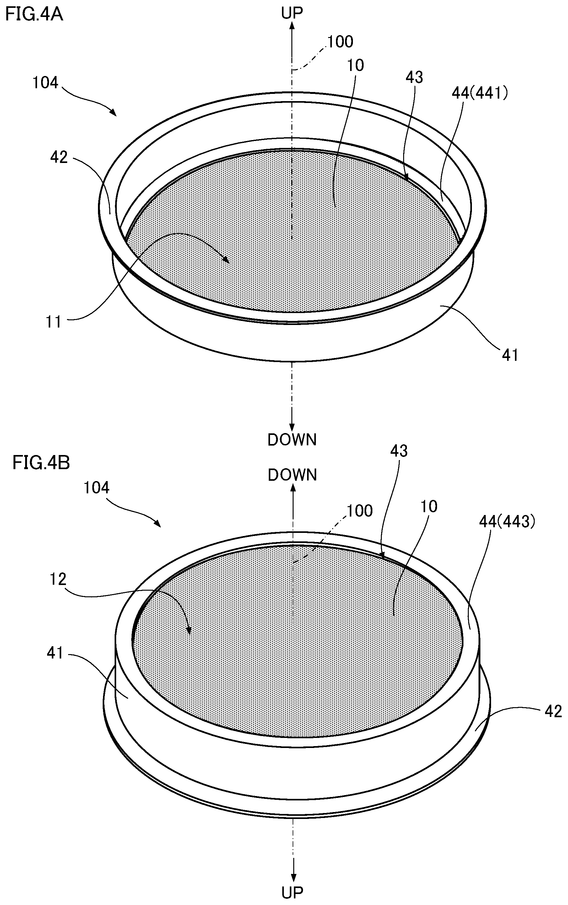
[0068] FIGS. 4A, 4B illustrate an inner lid 104 obtained by injection molding the frame 41 using the pad 10 as an insert member. FIG. 4A is a perspective view of the inner lid 104 as viewed from above, and FIG. 4B is a perspective view of the inner lid 104 as viewed from below. As illustrated in FIG. 4A, like the inner lid 4 of the cosmetic container 1 according to the embodiment illustrated in FIG. 1, the inner lid 104 is a vertically flattened hollow cylindrical frame 41 with an annular bottom having a double-ring structure 441, 443 formed on the lower end side and the flat pad 10 arranged between the rings 441, 443 of the double-ring structure. However, as illustrated in FIG. 4B, the inner lid 104 does not have a cut-out (reference numeral 49 in FIG. 3B) in the bottom ring 443 of the double-ring structure.
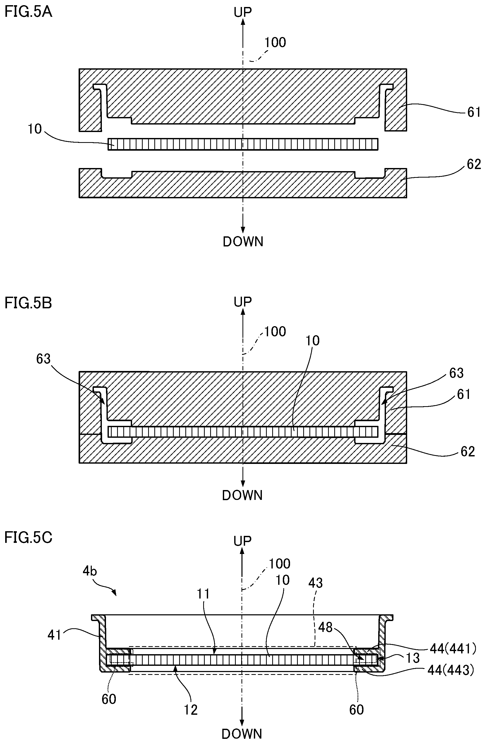
[0069] FIGS. 5A, 5B, 5C illustrate a procedure for forming the inner lid 104 illustrated in FIGS. 4A, 4B. First, as illustrated in FIG. 5A, a flat pad 10 is arranged in a mold 61, 62. Then, as illustrated in FIG. 5B, the molds (61, 62) are closed and the molten plastic is injected into the cavity 63. When the molded product is ejected from the molds 61, 62, the inner lid 104 illustrated in a vertical sectional view in FIG. 5C is obtained. In the inner lid 104, the peripheral region of the pad 10, that is, the outer peripheral surface 13 and the peripheral portion of the upper and lower surfaces 11, 12 are welded to the plastic constituting the frame 41 in the gap 48 formed between the rings 441, 443 of the double-ring structure. As a result, in the cosmetic container 1 provided with the inner lid 104, leakage of the cosmetic 5 via the contact interface 60 between the peripheral region of the pad 10 and the frame 41 is securely blocked. Alternatively, note that the bottom 44 need not have a double-ring structure, and only the lower bottom 443 may be provided, in which case the outer peripheral surface 13 and the peripheral portion of the lower surface 12 of the pad 10 are welded to the lower bottom 443.
[0070] Method of Impregnating the Pad with Cosmetic
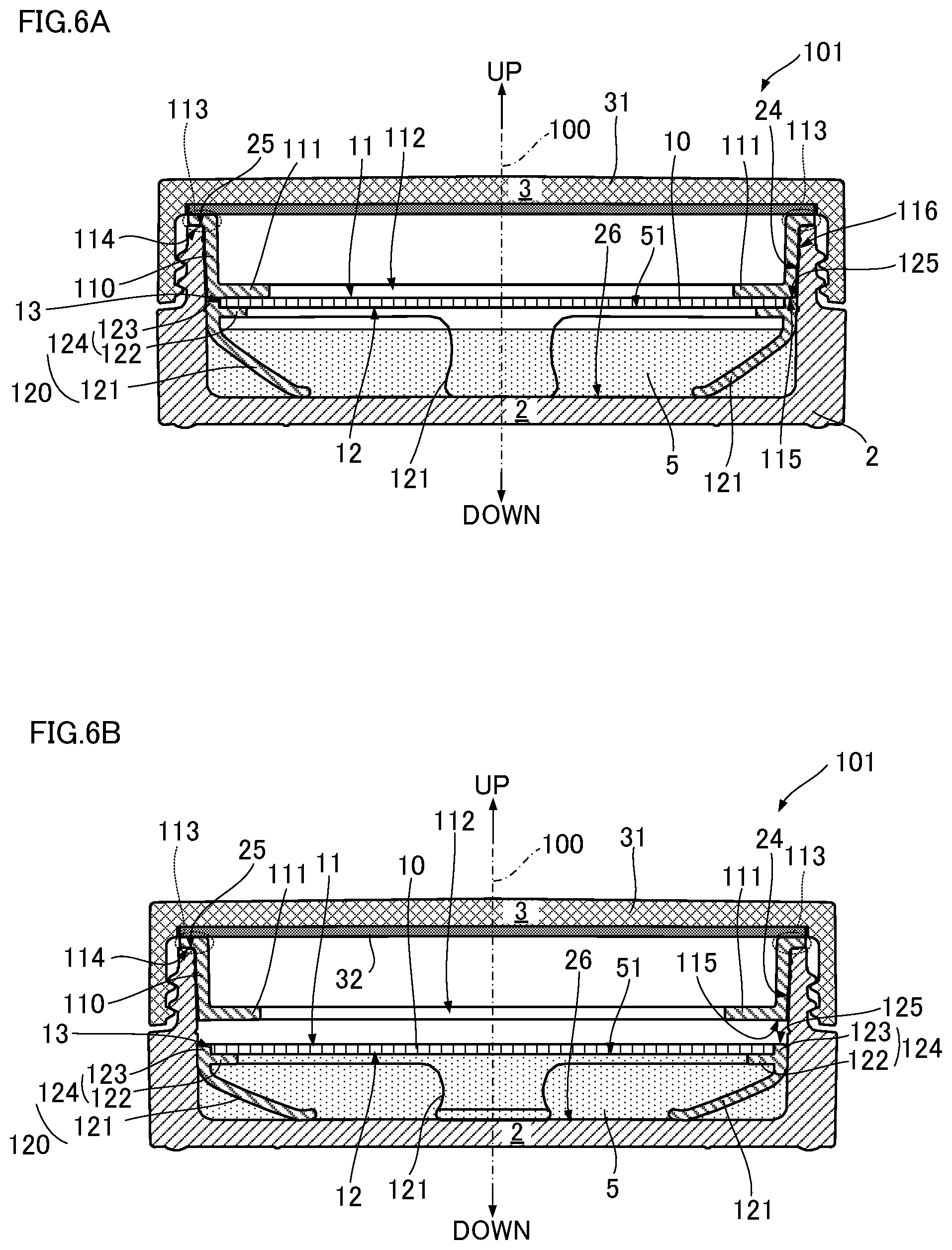
[0071] The cosmetic container 1 according to the embodiment may be provided with a mechanism for impregnating cosmetic 5 to the pad 10 while in the upright state. Schematically, referring to FIG. 2C, the mechanism moves the pad 10 returnably downward so as to be able to return the pad 10 to its initial state, and brings the lower surface 12 of the pad 10 into contact with the liquid level 51 of the cosmetic 5. FIGS. 6A, 6B and FIGS. 7A, 7B illustrate vertical sections of cosmetic containers 101, 201 provided with a mechanism for moving the pad 10 downward (hereinafter referred to as a pad moving mechanism). The cosmetic containers 101, 201 illustrated in FIGS. 6A, 6B and FIGS. 7A, 7B have an opening 112, 212 at the bottom 111, 211 and have a pad moving mechanism constituted by a frame fixed to the upper side of the container body 2 (hereinafter referred to as a fixed frame 110, 210) and a frame on which the pad 10 is mounted that moves the pad 10 in the vertical direction (a movable frame 120, 220).
[0072] In the cosmetic container 101 illustrated in FIGS. 6A, 6B, the pad moving mechanism is constituted by the fixed frame 110 and the movable frame 120 provided with leaf springs 121. FIG. 6A illustrates the arrangement of the movable frame 120 when the cosmetic 5 is not used, and FIG. 6B illustrates the arrangement of the movable frame 120 when the pad 10 is impregnated with the cosmetic 5. As illustrated in FIG. 6A, the fixed frame 110 is a single piece of molded plastic, and is detachably mounted on the container body 2. The fixed frame 110 has a vertically flattened hollow cylindrical shape. A flange 113 is formed at the upper end, and an opening 112 for exposing the upper surface 11 of the pad 10 is formed at the center of the bottom 111. That is, the fixed frame 110 has the same shape as the frame 41 constituting the inner lid 4 of the cosmetic container 1 illustrated in FIG. 1. When the fixed frame 110 is mounted on the container body 2, the lower surface 114 of the flange 113 contacts the upper end 25 of the container body 2 so as not to fall into the container body 2. The bottom 111 of the fixed frame 110 has a single-ring structure and no pad 10 is attached to the bottom 111.
[0073] The movable frame 120 is a single piece of molded plastic, having a frame-shaped portion (hereinafter referred to as a pad mounting frame 124) in which a peripheral wall surface 123 is erected upward and contacts an outer peripheral surface 13 of the pad 10 around the periphery of an annular bottom 122 supporting from below the peripheral portion of the lower surface 12 of the pad, and leaf springs 121 projecting downward from the pad mounting frame 124. The pad 10 is fixed in the pad mounting frame 124 by an appropriate method (adhesion, welding, or the like), and the leaf springs 121 are formed at equal angular intervals around the circumference of the bottom 122 of the pad mounting frame 124. In the movable frame 120 illustrated here, the leaf springs 121 are formed at four locations 90.degree. apart. The lower ends of the leaf springs 121 contact the bottom surface 26 of the container body 2.
[0074] When using the cosmetic 5, the pad 10 is pressed downward as the puff or the like is contacted against the upper surface 11 of the pad 10. As a result, as illustrated in FIG. 6B, the pad mounting frame 124 of the movable frame 120 moves downward compressing the leaf springs 121. When the lower surface 12 of the pad 10 contacts the liquid level 51 of the cosmetic 5, the pad 10 is impregnated with the cosmetic 5 and the cosmetic 5 is transferred from the upper surface 11 of the pad 10 to the puff. When the cosmetic 5 has been transferred, the pressing force on the pad 10 may be released. As a result, the pad mounting frame 124 is moved upward by the restoring force of the leaf springs 121, the upper end 125 of the pad mounting frame 124 contacts a lower end 115 of the fixed frame 110, and the pad mounting frame 124 returns to its initial state illustrated in FIG. 6A. The leaf springs 121 of the movable frame 120 are adjusted so that the upper end of the pad mounting frame 124 contacts the lower end of the fixed frame 110 when in a restored state in which the leaf springs 121 are not compressed downward or expanded upward. Further, the outer peripheral surface 116 of the fixed frame 110 presses against the inner surface 24 of the container body 2, so that the fixed frame 110 does not readily fall out of the container body 2 even when pushed from below. That is, even if the upper end 125 of the pad mounting frame 124 contacts the lower end 115 of the fixed frame 110 in a state in which the leaf springs 121 are compressed, the fixed frame 110 does not separate upward from the container body 2.
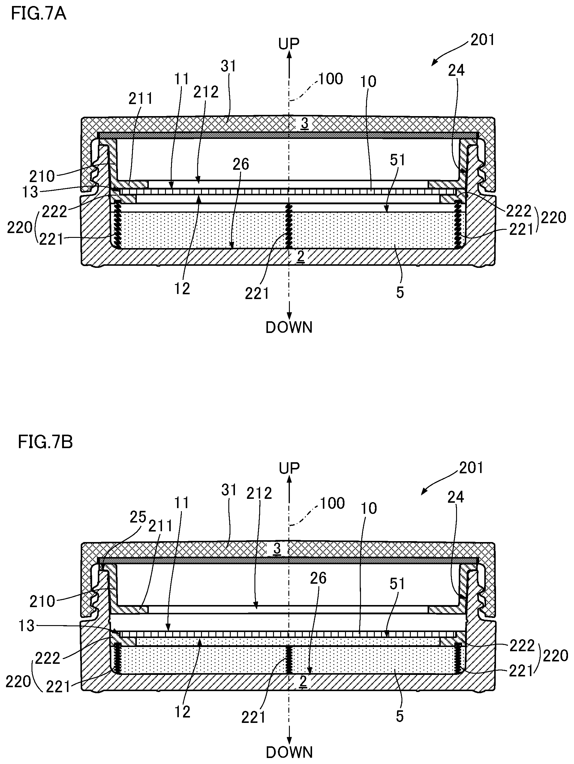
[0075] In the cosmetic container 201 illustrated in FIGS. 7A, 7B, the pad moving mechanism is constituted by the fixed frame 210 and the movable frame 220 to which coil springs 221 are attached. With respect to the cosmetic container 101 illustrated in FIGS. 6A, 6B, the only difference is that the leaf springs 121 are replaced by the coil springs 221.
[0076] FIG. 7A illustrates the state of the movable frame 220 when the cosmetic 5 is not used, and FIG. 7B illustrates the state of the movable frame 220 when the pad 10 is impregnated with the cosmetic 5. As illustrated in FIG. 7A, the fixed frame 210 is the same as that illustrated in FIGS. 6A, 6B. Coil springs 221 having vertical spiral axes are attached to the lower end of the pad mounting frame 222 of the movable frame 220, which is similar to that illustrated in FIG. 6A, 6B. As illustrated in FIG. 7B, when the upper surface 11 of the pad 10 is pressed downward, the coil springs 221 are compressed between the pad mounting frame 222 and the bottom surface 26 of the container body 2 and the pad 10 contacts the liquid level 51 of the cosmetic 5. Then, when the pressing force on the pad 10 is released, the pad mounting frame 222 is moved upward by the restoring force of the coil springs 221 and returns to its initial state as illustrated in FIG. 7A.
[0077] In the cosmetic containers 101, 201 illustrated in FIGS. 6A, 6B and FIGS. 7A, 7B, the pad mounting frames 124, 222 of the movable frames 120, 220 may be configured so as to hold the pad 10 by the same structure as the frame 41 illustrated in FIGS. 3A-3C or the bottom 44 of the double-ring structure of the inner lid 104 illustrated in FIGS. 5A-5C.
[0078] In the cosmetic containers 101, 201 illustrated in FIGS. 6A, 6B and FIGS. 7A, 7B, the pad moving mechanism is composed of fixed frames 10, 210 and movable frames 120, 220. However, for example, the flange 42 need not be provided on the inner lid 4 of the cosmetic container 1 illustrated in FIG. 1 or the inner lid 104 illustrated in FIGS. 4A, 4B and a spring mechanism such as a leaf spring 121 or a coil spring 221 may be provided to the lower bottom portions 442, 443 of the inner lids 4, 104, so that the inner lid 4, 104 itself can be moved downward so as to be able to return.
[0079] The container body 2 may be formed of a light-transmissive material, so that a mark indicating the maximum amount of the cosmetic 5 can be provided on the outer surface of the container body 2. Alternatively, a mark provided on the inner surface 24 of the container body 2 can be ascertained from the outside. Further, if the container body 2 is formed of a light-transmissive material, the cosmetic 5 in the container body 2 can be visually observed, so that amount of the cosmetic 5 remaining in the cosmetic container 1 can be ascertained accurately without turning over or shaking the cosmetic container 1. When the cosmetic 5 is colored, the container body 2 may be formed of a colorless and transparent light-transmissive material, such that the color of the cosmetic 5 can be visually recognized from the outside and the cosmetic 5 can be stored or displayed in a pleasing manner.
[0080] Although the cosmetic containers 1, 101, 201 according to the above-mentioned embodiment are flat and cylindrical, other shapes, such as a rectangular tube shape, are possible provided that the outer lid 3 for sealing the container body 2 and the inner lid 4 on which the pad 10 is mounted 4 and a configuration corresponding to the movable frame 120, 220 are provided. The inner lid 4 can be omitted if an annular projection for supporting the pad 10 is formed on the inner surface 24 of the container body 2.
* * * * *
D00000
D00001
D00002
D00003
D00004
D00005
D00006
D00007
XML
uspto.report is an independent third-party trademark research tool that is not affiliated, endorsed, or sponsored by the United States Patent and Trademark Office (USPTO) or any other governmental organization. The information provided by uspto.report is based on publicly available data at the time of writing and is intended for informational purposes only.
While we strive to provide accurate and up-to-date information, we do not guarantee the accuracy, completeness, reliability, or suitability of the information displayed on this site. The use of this site is at your own risk. Any reliance you place on such information is therefore strictly at your own risk.
All official trademark data, including owner information, should be verified by visiting the official USPTO website at www.uspto.gov. This site is not intended to replace professional legal advice and should not be used as a substitute for consulting with a legal professional who is knowledgeable about trademark law.