Food Container
Lane; Marvin ; et al.
U.S. patent application number 16/853317 was filed with the patent office on 2020-10-29 for food container. The applicant listed for this patent is Thermos L.L.C. Invention is credited to Freddy Aranda, Dwayne Boroski, Marvin Lane.
| Application Number | 20200337428 16/853317 |
| Document ID | / |
| Family ID | 1000004785620 |
| Filed Date | 2020-10-29 |


View All Diagrams
| United States Patent Application | 20200337428 |
| Kind Code | A1 |
| Lane; Marvin ; et al. | October 29, 2020 |
FOOD CONTAINER
Abstract
A food container includes a base including one or more compartments. A lid is configured to engage to the base. A lower surface of the lid includes closing members. The closing members include a central portion formed from a first material and a distal portion formed from a second material. The central portion extends from or is integral with the lower surface of the lid. The closing members close the one or more compartments. The distal portion compresses or seals against an upper surface of the base or an insert positioned in one of the one or more compartments.
| Inventors: | Lane; Marvin; (Wheeling, IL) ; Boroski; Dwayne; (Lake in the Hills, IL) ; Aranda; Freddy; (Chicago, IL) | ||||||||||
| Applicant: |
|
||||||||||
|---|---|---|---|---|---|---|---|---|---|---|---|
| Family ID: | 1000004785620 | ||||||||||
| Appl. No.: | 16/853317 | ||||||||||
| Filed: | April 20, 2020 |
Related U.S. Patent Documents
| Application Number | Filing Date | Patent Number | ||
|---|---|---|---|---|
| 62837599 | Apr 23, 2019 | |||
| 62877367 | Jul 23, 2019 | |||
| Current U.S. Class: | 1/1 |
| Current CPC Class: | A45C 5/02 20130101; A45C 13/1046 20130101; A45C 13/02 20130101; B65D 25/04 20130101; A45C 11/20 20130101 |
| International Class: | A45C 13/02 20060101 A45C013/02; A45C 11/20 20060101 A45C011/20; A45C 5/02 20060101 A45C005/02; A45C 13/10 20060101 A45C013/10; B65D 25/04 20060101 B65D025/04 |
Claims
1. A food container, comprising: a base comprising one or more compartments; a lid configured to engage to the base; and, a lower surface of the lid comprises closing members, wherein the closing members include a central portion formed from a first material and a distal portion formed from a second material, and the central portion extends from or is integral with the lower surface of the lid; and wherein the closing members close the one or more compartments.
2. The food container according to claim 1, wherein the distal portion of the closing members is formed from a thermoplastic elastomer.
3. The food container according to claim 1, wherein the distal portion compresses or seals against an upper surface of the base or an insert positioned in one of the one or more compartments, and wherein the second material forming the distal portion is more compressible than the first material forming the central portion.
4. The food container according to claim 1, wherein the food container comprises an open configuration in which an interior of the food container is accessible and a closed configuration in which the lid is closed over the base, wherein in the closed configuration, the distal portion compresses or seals against an upper surface of the base to reduce leakage or intermingling of food items in the compartments.
5. The food container according to claim 1, wherein the distal portion is integral with the central portion.
6. The food container according to claim 1, wherein the distal portion is molded over the central portion.
7. The food container according to claim 1, wherein the food container comprises an open configuration in which an interior of the food container is accessible and a closed configuration in which the lid is closed over the base, wherein in the closed configuration, a fastener extends from the base and secures to the lid.
8. A food container, comprising: a lid comprising a lid inner member and a lid outer member; a base comprising a base inner member and a base outer member; the lid configured to engage to the base; a lower surface of the lid inner member comprises closing members, wherein the closing members include a central portion formed from a first material and a distal portion formed from a second material; the base inner member forms one or more compartments to receive one or more inserts or one or more food items; and, wherein the closing members close the one or more compartments when the lid is in a closed position.
9. The food container according to claim 8, wherein the lid inner member and the lid outer member click or snap-fit together, and wherein the lid inner member and the lid outer member are separable.
10. The food container according to claim 8, wherein the base inner member and the base outer member slide together, and wherein the base inner member and the base outer member are separable.
11. The food container according to claim 8, wherein the food container comprises an open configuration in which an interior of the food container is accessible and a closed configuration in which the lid is closed over the base, wherein in the closed configuration, the distal portion compresses or seals against an upper surface of the base inner member to reduce leakage or intermingling of food items in the compartments, and wherein the distal portion is molded over the central portion.
12. The food container according to claim 8, wherein the food container comprises an open configuration in which an interior of the food container is accessible and a closed configuration in which the lid is closed over the base, wherein in the closed configuration, the distal portion is urged against an upper surface of the base inner member to reduce leakage or intermingling of food items in the compartments, and wherein the second material forming the distal portion is more compressible than the first material forming the central portion.
13. The food container according to claim 8, wherein the lid inner member, the base inner member, or both the lid inner member and the base inner member are removable from the food container.
14. The food container according to claim 8, wherein the lid and the base are joined together via a hinging or pivoting connection, and a fastener extends from the base outer member to engage the lid outer member to hold the lid and the base in a closed configuration.
15. The food container according to claim 8, wherein the lid inner member is secured to the lid outer member via welding, clinching, adhering, magnets, laser connection, or other method, or the base inner member is secured to the base outer member via welding, clinching, adhering, magnets, laser connection, or other method.
16. The food container according to claim 8, wherein multiple inserts fit into a single compartment.
17. The food container according to claim 8, wherein two semi-circular shaped inserts fit into a single, circular-shaped compartment or two smaller rectangular or square-shaped inserts fit into a single, larger rectangular or square-shaped compartment.
18. A food container, comprising: a tray lid; a tray base; the tray lid and the tray base configured to join together in a closed configuration; a flexible strap removably fastens to the tray lid and to the tray base to hold the tray lid and the tray base in the closed configuration; and, the flexible strap removably fastens to a front portion of the tray lid, spans from the front portion of the tray lid, around a front wall of the tray base, around a lower surface of the tray base, around a rear wall of the tray base, and to a rear portion of the tray lid; and wherein the flexible strap removably fastens to the rear portion of the tray lid.
19. The food container according to claim 18, wherein the strap includes a first end that is generally opposite of a second end, the first end includes an opening that removably engages to a protruding member formed on an exterior surface of an upper wall of the tray lid, and the second end includes a fastener that removably engages to an opening in a rear surface of the tray lid.
20. The food container according to claim 18, wherein the tray lid includes a front channel and a rear channel that generally receives a width of the strap, and the tray base include a tray base channel extending from a front wall of the tray base, around a lower surface of the tray base, and to a rear wall of the tray base, and the tray base channel generally receives the width of the strap.
Description
CROSS-REFERENCE TO RELATED APPLICATIONS
[0001] This application claims priority to U.S. Provisional Application No. 62/837,599 filed Apr. 23, 2019 and U.S. Provisional Application No. 62/877,367 filed Jul. 23, 2019.
FIELD OF INVENTION
[0002] The present invention relates to a food container.
SUMMARY
[0003] A food container is described. The food container includes a lid and a base. The lid is configured to engage to the base. The base forms an interior with compartments to hold a variety of food items, condiments, seasonings, utensils, food containers, ice packs, etc. The lid includes closing members to close the compartments and help prevent leakage or comingling of the food items.
[0004] In one aspect, the closing members include a central portion formed from a first material and a distal portion formed from a second material. The distal portion seals or compresses against certain sections of the base. The second material is generally softer or more compressible than the first material.
[0005] In one aspect, the distal portion may be over molded to the central portion. This bonds or connects the distal portion to the central portion.
[0006] In another aspect, the softer distal portion seals or compresses against the base, which is formed from a more rigid material. A seal formed between the distal portion and the base reduces leakage or comingling of the food items.
[0007] In another aspect, the closing member extends downward from a lower surface of the lid. The central portion extends from or is integral with the lower surface of the lid. The distal portion is integral with the central portion.
[0008] In another aspect, a food container includes a base including one or more compartments. A lid is configured to engage to the base. A lower surface of the lid includes closing members. The closing members include a central portion formed from a first material and a distal portion formed from a second material. The central portion extends from or is integral with the lower surface of the lid. The closing members close the one or more compartments.
[0009] In another aspect, a food container includes a food container including a lid including a lid inner member and a lid outer member. A base includes a base inner member and a base outer member. The lid is configured to engage to the base. A lower surface of the lid inner member includes closing members. The closing members include a central portion formed from a first material and a distal portion formed from a second material. The base inner member forms one or more compartments to receive one or more inserts or one or more food items. The closing members close the one or more compartments when the lid is in a closed position.
[0010] A second food container is also described. The second food container includes a tray lid and a tray base. The tray lid is configured to engage to the tray base. A strap holds the tray lid engaged to the tray base. The second food container forms an interior to hold a variety of food items, condiments, seasonings, utensils, food containers, etc. The strap normally prevents the tray lid and the tray base from separating until the strap is disengaged by the user. The strap may be easily disengaged from the second food container by the user in order open the second food container.
[0011] In another aspect, the second food container includes a tray lid and a tray base. The tray lid and the tray base are configured to join together in a closed configuration. A flexible strap removably engages to the tray lid and to the tray base to hold the tray lid and the tray base in the closed configuration. The strap bends and flexes around a substantial portion of an exterior surface of the second food container. The strap connects to both a top portion and a rear portion of the second food container to securely close the second food container.
[0012] In another aspect, the second food container includes a tray lid and a tray base. The tray lid and the tray base are configured to join together in a closed configuration. A flexible strap removably fastens to the tray lid and to the tray base to hold the tray lid and the tray base in the closed configuration. The flexible strap removably fastens to a front portion of the tray lid, spans from the front portion of the tray lid, around a front wall of the tray base, around a lower surface of the tray base, around a rear wall of the tray base, and to a rear portion of the tray lid. The flexible strap removably fastens to the rear portion of the tray lid.
BRIEF DESCRIPTION OF DRAWINGS
[0013] FIG. 1 is a perspective view of the food container in the closed configuration.
[0014] FIG. 2 is a perspective view of the food container in the opened configuration.
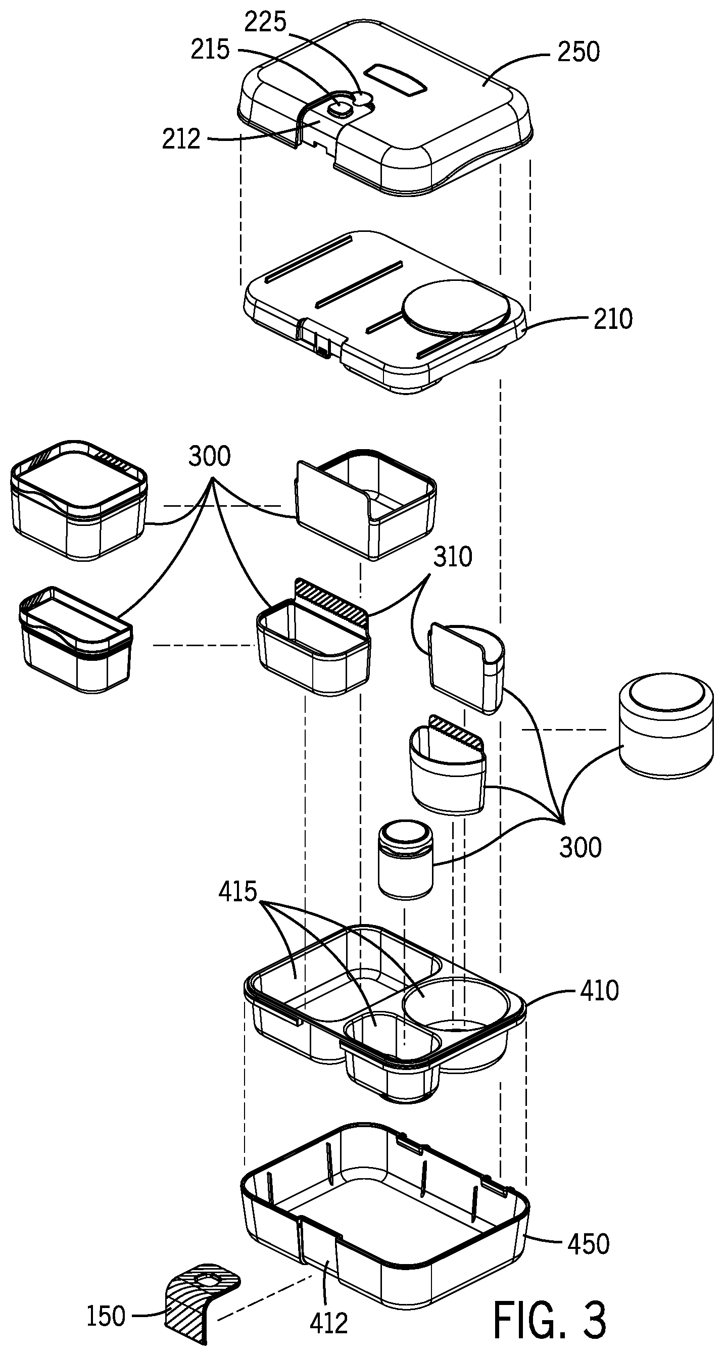
[0015] FIG. 3 is an exploded view of the food container.
[0016] FIG. 4 is an exploded view of the food container.
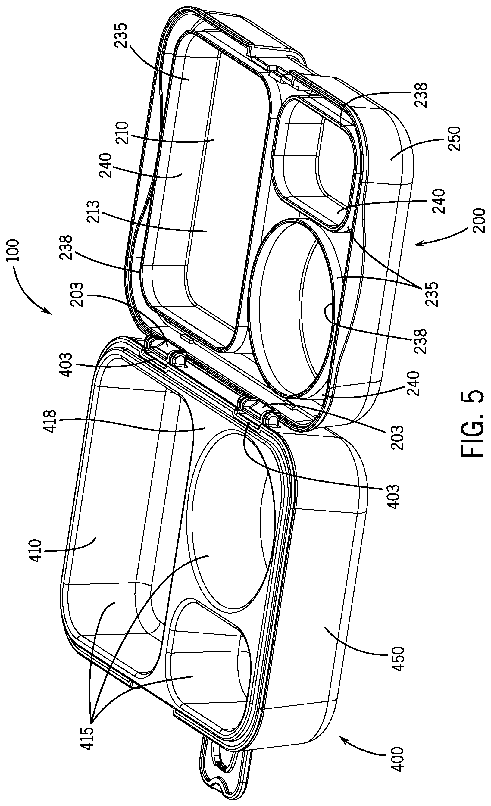
[0017] FIG. 5 is a perspective view of the food container in the opened configuration.
[0018] FIG. 6 is a perspective view of the food container in the opened configuration.
[0019] FIG. 7 is an exploded view of the food container.
[0020] FIG. 8 is a sectional view of the food container in the opened configuration.
[0021] FIG. 8A is a sectional view of the food container showing the strap.
[0022] FIG. 8B is a sectional view of the food container showing the hinge.
[0023] FIG. 8C is a sectional view of the food container showing the lid inner member and the lid outer member.
[0024] FIG. 9 is a sectional view of the food container showing the distal portion contacting the upper surface of the base inner member.
[0025] FIG. 10 is a sectional view of the food container showing the distal portion contacting the upper surface of the base inner member.
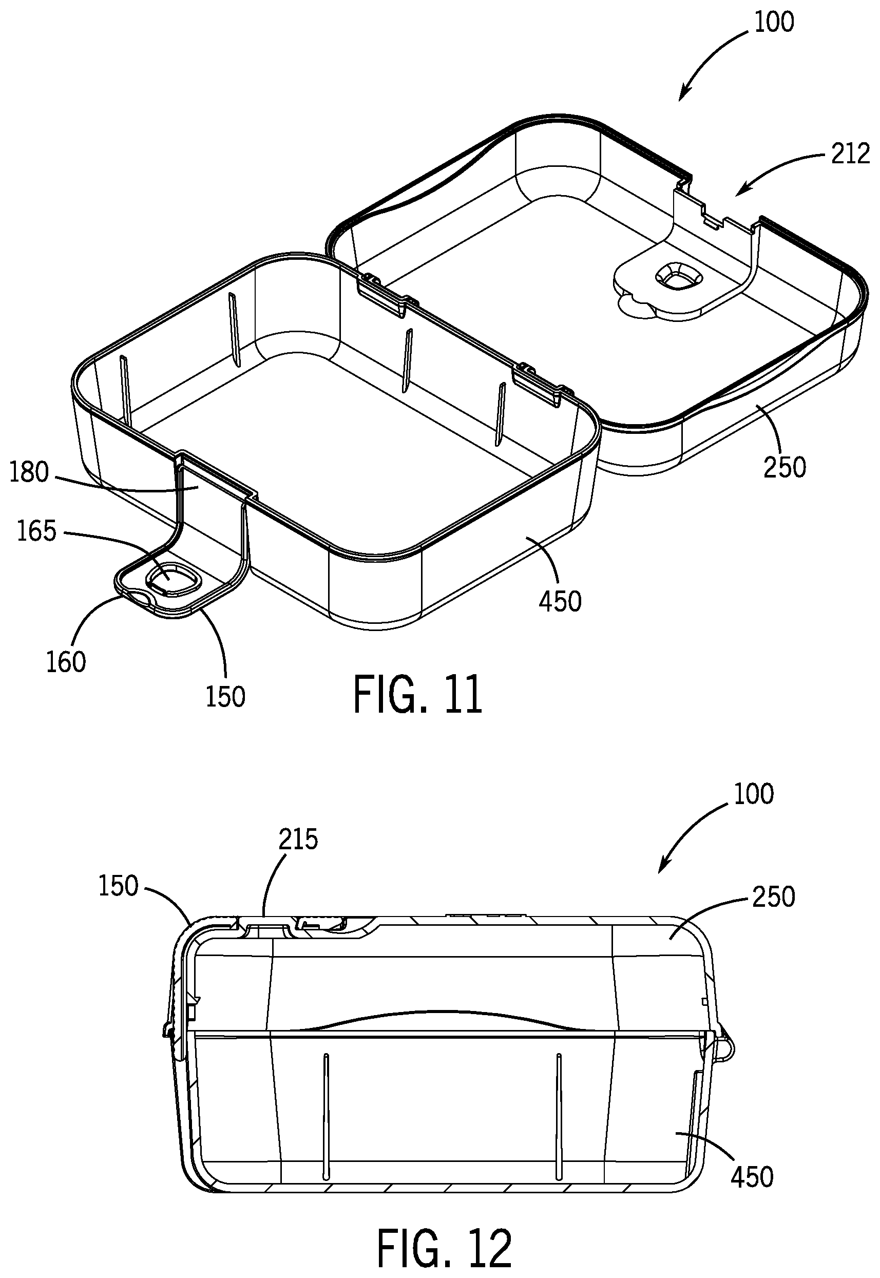
[0026] FIG. 11 is a perspective view of the food container in the opened configuration with the lid inner member and the base inner member removed.
[0027] FIG. 12 is a sectional view of the food container with the lid inner member and the base inner member removed.
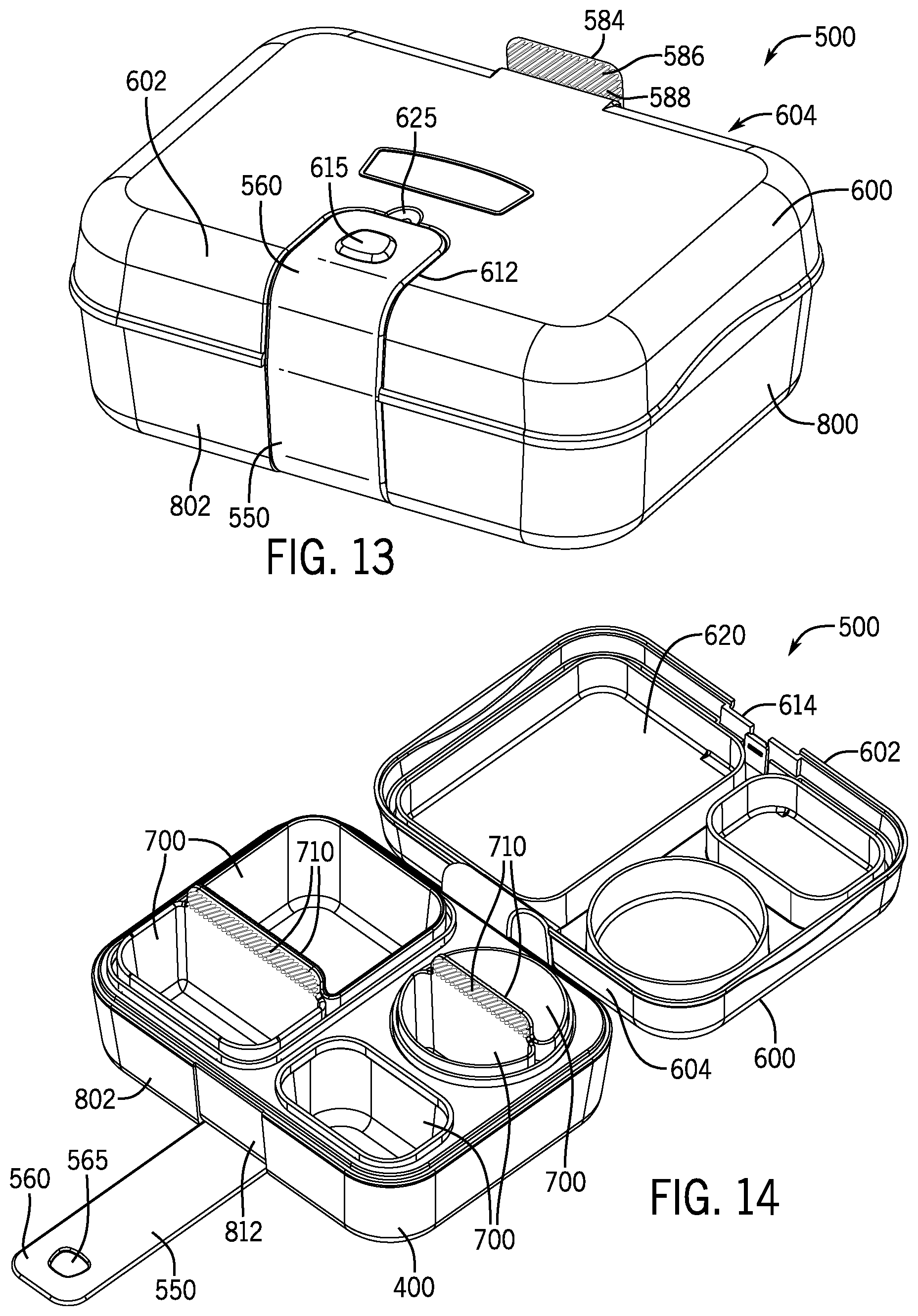
[0028] FIG. 13 is a perspective view of a second food container in the closed configuration.
[0029] FIG. 14 is a perspective view of the second food container in the opened configuration.
[0030] FIG. 15 is an exploded view of the second food container.
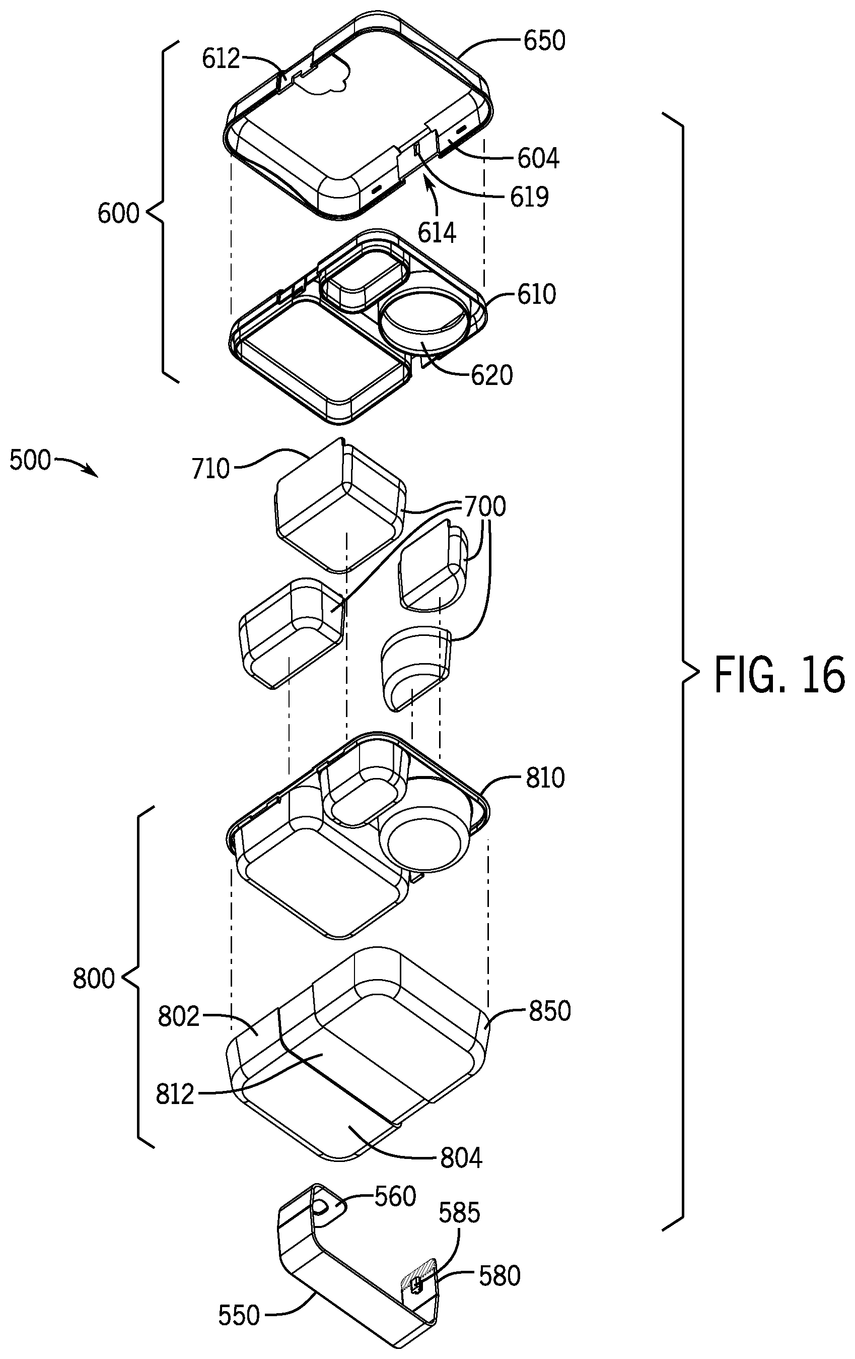
[0031] FIG. 16 is an exploded view of the second food container.
[0032] FIG. 17 is a top view of the second food container.
[0033] FIG. 18 is a sectional view of the second food container.
[0034] FIG. 19 is a sectional view of the second food container showing the protruding member.
[0035] FIG. 20 is a sectional view of the second food container showing the fastener.
[0036] FIG. 21 is a sectional view of the second food container showing the strap flush against the tray base.
DETAILED DESCRIPTION OF INVENTION
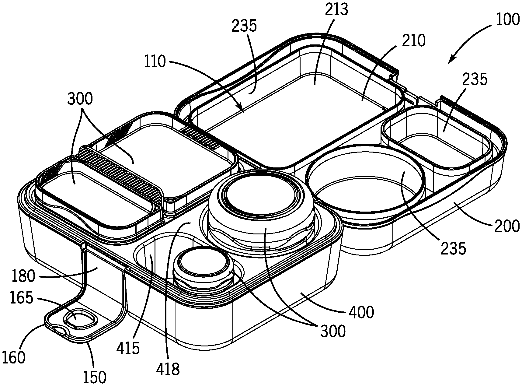
[0037] For purposes of this application, any terms that describe relative position (e.g., "upper", "middle", "lower", "outer", "inner", "above", "below", "bottom", "top", etc.) refer to an embodiment of the invention as illustrated, but those terms do not limit the orientation in which the embodiments can be used. A food container 100 is described. The food container 100 may include a generally rectangular or square shape that forms an interior 110 to hold a variety of food items, condiments, seasonings, utensils, food containers, ice packs, etc. The food container 100 generally keeps certain food items separate and contained, such that the food items do not intermix, spill, and/or leak from the food container 100. A width, depth, and length of the food container 100 may be scaled up or down depending upon the needs of the user, the intended application, etc.
[0038] The food container 100 generally includes a lid 200 and a base 400. The lid 200 and the base 400 join together to define the interior 110. The lid 200 and the base 400 may join together via a hinging or pivoting connection or may have a mating connection with a tie down or other complementary configuration. In this aspect, with respect to FIGS. 5 and 6, the lid hinges 203 hingedly connect with base hinges 403 to provide hinging movement. The lid 200 opens relative to the base 400 to an open configuration to reveal the interior 110 of the food container 100. Other aspects may include fasteners or other removable connection facilitators on one or more sides of the lid 200.
[0039] The lid 200 includes a lid inner member 210 and a lid outer member 250. The lid inner member 210 is sized and shaped to fit at least mostly or entirely within the lid outer member 250. In this aspect, the lid inner member 210 and the lid outer member 250 slide, click, or snap-fit together in a removable or separable manner. In other aspects, the lid inner member 210 and the lid outer member 250 may press-fit, friction-fit, slide together or otherwise nest together in both removable and irremovable configurations.
[0040] Similarly, in this aspect, the base 400 includes a base inner member 410 and a base outer member 450. The base inner member 410 is sized and shaped to fit at least mostly or entirely within the base outer member 450. The base inner member 410 and the base outer member 450 may slide together in a removable or separable manner. With respect to FIG. 7, a holding member 422 formed on an outer wall 424 of the base inner member 410 holds against the base outer member 450. The holding member 422 may wedge against an inner surface 452 of the base outer member 450. In other aspects, the base inner member 410 and a base outer member 450 may snap-fit, press-fit, friction-fit or otherwise nest together in both removable and irremovable configurations.
[0041] The lid outer member 250 forms an outer exterior for the lid 200, while the lid inner member 210 forms a lower surface 213 shaped or configured to close inserts 300 and/or compartments 415 when the lid 200 is engaged to the base 400. The lid inner member 210 and the lid outer member 250 may be separated for washing. In other aspects, the lid 200 is a single piece member or otherwise not configured to be separable. For example, the lid inner member 210 and lid outer member 250 may be configured not to be removed from one another and may be secured together via welding, clinching, adhering or other method. Similarly, the base inner member 410 and base outer member 450 may be configured not to be removed from one another and may be secured together via welding, clinching, adhering or other method.
[0042] An insulation space may be formed between the lid inner member 210 and the lid outer member 250. Similarly, an insulation space may be formed between the base inner member 410 and the base outer member 450. The insulation space may be vacuum insulated, foam insulated, insulated with a layer of air, or include other insulation that helps minimize temperature change within the interior 110.
[0043] In the aspect shown in FIGS. 1-12, the lid inner member 210 and the lid outer member 250 are separable such that the user can clean the components, or choose to use only the lid outer member 250 with the base 400 to increase storage space. For example, juice boxes, bags of chips, fruit cups, etc. may fit better in the interior 110 without lid inner member 210. For example, an ice pack may fit over the base inner member 410 more easily without the lid inner member 210.
[0044] In further aspects, the lid inner member 210 and the lid outer member 250 are separable and the base inner member 410 and the base outer member 450 are separable such that the user could only use the lid outer member 250 with the base outer member 450 to maximize the space for food storage. For example, certain large food products may fit better in the interior 110 without the lid inner member 210 and the base inner member 410. Or, for example, the compartments 300 may not be needed for certain food products.
[0045] In this aspect, the lid inner member 210 and the lid outer member 250 connect via a tab that biases with a catch. For example, as shown in FIG. 7, a front wall of the lid inner member 210 includes a tab 214 that biases against a catch 202 formed in or by a front portion 204 of the lid outer member 250. Other structures may be used to removably connect the lid inner member 210 and the lid outer member 250.
[0046] The base inner member 410 forms the one or more compartments 415 to receive the one or more inserts 300 or one or more food items. The compartments 415 may be depressions or wells in an upper surface 418 of the base inner member 410. The base outer member 450 forms an outer exterior for the base 400. The base inner member 410 and the base outer member 450 may be separated for washing. In other aspects, the base 400 is a single piece member or otherwise not configured to be separable. In certain aspects, the lid 200 and base 400 may both be single piece members, or just the lid 200 may be a single piece member or just the base 400 may be a single piece member.
[0047] In this aspect, a fastener 150 configured as a strap holds the lid 200 and the base 400 together in a closed configuration. The fastener 150 prevents the lid 200 and the base 400 from opening when the fastener 150 is engaged. In other aspects, a buckle, clasp, latch, magnet, or other fasteners may be used to hold the lid 200 and the base 400 together. The strap 150 may be formed from a pliable or flexible material, such as silicone or flexible plastic, or in other aspects, it may be formed from a harder plastic, metal, or other material.
[0048] FIG. 1 is a perspective view of the food container 100 in the closed configuration. The food container 100 includes a box-like construction enclosing the interior 110. FIG. 2 is a perspective view of the food container 100 in an open configuration.
[0049] When the user desires to open the food container 100, the strap 150 is disengaged, which includes pulling the strap 150 away from a fastener receiving structure 215 of the lid 200. Now, the lid 200 may be opened. The base 400 holds the food items in position, which may be useful if the user is eating from the base 400 at a desk, school, cafeteria, school lunch room, etc. or while traveling in a car, bus, plane, train, etc.
[0050] The base 400 forms the one or more compartments 415 to receive one or more inserts 300 or one or more food items. The one or more compartments 415 may include a number of different shapes of varying sizes. For example, the compartments 415 may include a circular, square, rectangular, ovular, or other shape. For example, a large rectangular compartment may be formed to receive a sandwich or an insert 300 holding a sandwich. Other food items or beverage items may be placed in the one or more compartments 415 or in the one or more inserts 300 which are placed in the one or more compartments 415. The compartments 415 may be configured to receive a specific type of food jar, food container, beverage bottle, juice box, condiments, non-packaged food such as fruit, vegetable, sandwich, other food or beverage items, or even non-edible items such as a straw, spoon, other utensils, or ice pack.
[0051] The inserts 300 may be configured as cups, containers, and other holding structures that fit into the compartments 415. In certain aspects, multiple inserts 300 may fit into a single compartment. For example, with reference to FIG. 3, two semi-circular inserts 300 fit into a single, circular shaped compartment 415. For example, with reference to FIGS. 3 and 4, two smaller rectangular inserts 300 fit into a single, large rectangular shaped compartment 415. Such insert pairs may be available in different sizes or in various configurations to permit the user to customize how the compartments 415 are used. The inserts 300 also may be adjustable in size. Each insert 300 may be a different size or shape. Such inserts 300 may be configured to permit the user to separate food to help with portion size or avoid comingling items that might get soggy if exposed to one another during transport. The inserts 300 may include a handle 310 or a cover (not shown). In the illustrated aspect, the handle 310 is configured as an elevated patterned surface that permits the user to grasp the insert 300 and easily remove from the compartment 415. However, the inserts 300 could have other handle shapes such as raisable handles, bail handles, flat handles, adjustable handles, or any other handle.
[0052] In this aspect, the lid inner member 210 includes the lower surface 213 shaped or configured to close the inserts 300 and/or the compartments 415 when the lid 200 is engaged to the base 400. The lower surface 213 may include complementary sealing or closing structures to seal and/or close the inserts 300 and/or the compartments 415. In certain aspects, a sealing surface such as a gasket may be added to one or more of the sealing or closing structures to decrease the likelihood of comingling contents among the inserts 300 or compartments 415.
[0053] In the aspects shown, the lower surface 213 of the lid inner member 210 includes one or more closing members 235. The closing members 235 decrease the likelihood of comingling contents among the inserts 300 or compartments 415 or spilling the contents. The closing members 235 are generally shaped complementary to the shape of the inserts 300 and/or the compartments 415 such that the closing members close or seal the inserts 300 and/or the compartments 415 when the lid 200 is engaged to the base 400. The number of closing members 235 present will generally depend on the number of inserts 300 and/or the compartments 415 present. The closing members 235 may include circular, square, rectangular, ovular, or other shapes to match the shapes of the compartments 415.
[0054] The closing members 235 extend toward the base 400. The closing members 235 extend generally downward from the lower surface 213 of the lid inner member 210. The closing members 235 are generally within an outer perimeter of the lid inner member 210. The closing members 235 may include walls and other structures integral with the lower surface 213 of the lid 200. The closing members 235 may be formed from a first material and a second material, wherein the first and second materials are different in composition. The closing members 235 may be formed using molding or over-molded techniques.
[0055] In this aspect, the closing members 235 include a distal portion 238 and a central portion 240. The central portion 240 extends from or is integral with the lower surface 213 of the lid inner member 210. In this aspect, the central portion 240 and the distal portion 238 are formed from different materials.
[0056] In this aspect, the distal portions 238 of the closing members 235 are formed from a thermoplastic elastomer (TPE) or other thermoplastic rubbers. Such materials may be used in over-molding processes to form the closing members 235 with the distal portions 238. The thermoplastic elastomers used for the distal portions 238 are more compressible than the materials used in the construction of the lid inner member 210. The thermoplastic elastomers provide a soft or rubbery lower edge to the closing members 235 that seals or compresses against the base 400. In other aspects, the distal portion(s) 238 may be made from any compressible or flexible material such as silicone, another rubber product, another elastomer or polymer product, for example.
[0057] In this aspect, the lid inner member 210, including the central portion 240 of the closing members 235 are formed from a harder, more rigid material, such as polypropylene.
[0058] When the lid 200 and the base 400 are joined together, the distal portions 238 are urged against the base inner member 410 or the inserts 300. The distal portions 238 may compress, seal, or abut against an upper surface 418 of the base inner member 410 or the inserts 300. This contact between the distal portions 238 and the upper surface 418 or the inserts 300 helps to reduce leakage or intermingling of food items in the compartments 415 or the inserts 300. In certain aspects, the sealing of the distal portions 238 against the base inner member 410 or the inserts 300 may provide water-resistant protection from leakage.
[0059] The closing members 235 may extend from the lower surface 213 of the lid inner member 210 in a shape, pattern, or configuration to approximately match, correspond to, or be complementary with the shape of the compartments 415, such that the compartments 415 are generally closed by the closing members 235. The closing members 235 may include slightly larger size than a size of the compartments 415, such that the closing members 235 seal against the upper surface 418 of the base inner member 410 adjacent to or proximal openings or rims of the compartments 415.
[0060] In one aspect, during the manufacturing process, the distal portions 238 are over-molded to the central portions 240. The over-molding process bonds, for example, chemically or structurally, the distal portions 238 to the central portions 240. The over-molding process generally avoids the use of glues and adhesives. In this aspect, the distal portions 238 are not intended to be removable from the central portions 240. In other aspects, the distal portions 238 may be configured to be removably seated on the central portions 240, adhered to the central portions 240, interwoven with the central portions 240, or otherwise positioned adjacent to the central portions 240. In still other aspects, one or more of the distal portions 238 made of a compressible material may be positioned relative to a section of the base 400, for example, a rim of an insert 300 or rim of a compartment 415.
[0061] The fastener 150 configured as a strap 150 holds the lid 200 and the base 400 together in a closed configuration. The strap 150 includes a generally flat structure or possibly a curvable structure or a bent structure that extends from the base 400 to the lid 200. In this aspect, the lid 200 includes a front channel 212, which generally receives a width of the strap 150. The base 400 includes a base channel 412, which may receive the width of the strap 150 when the strap 150 is undone from the fastener receiving structure 215, such as a protruding member.
[0062] The strap 150 generally includes a first end 160 that is generally opposite of a second end 180. In this aspect, the first end 160 includes an opening 165 and the second end 180 is hingedly engaged to the base 400. In this aspect, the opening 165 removably engages to the protruding member 215, such as a button or protrusion, formed on an exterior surface of an upper wall of the lid 200. In other aspects, the second end 180 may be affixed, fastened or otherwise integrated to the base.
[0063] A depression 225 may be formed in the exterior surface of the upper wall of the lid 200 adjacent to an end of the front channel 212. The depression 225 assists the user in getting their finger under the first end 160 of the strap 150 such that the user can pull the strap 150 from the protruding member 215 and disengage the opening 165 from the protruding member 215. In this aspect, the protruding member 215 is positioned in the front channel 212 of the lid 200.
[0064] In other aspects, where the strap 150 is not hinged to the base 400, the second end 180 of the strap 150 may include a tab portion. An interior surface of the tab portion may include a texture, such as a knurled surface or other pattern that provide an improved gripping surface for the user to grab onto and pull in order to disengage the strap 150 from the food container 100.
[0065] In further aspects, as shown in FIGS. 11 and 12, the food container 100 may provide additional utility if user wishes to repurpose the food container 100. For example, in certain aspects, the lid inner member 210 and the lid outer member 250 are separable and the base inner member 410 and the base outer member 450 are separable. The user may only use the lid outer member 250 with the base outer member 450 to maximize internal storage space. The user may store pencils, toys, arts and crafts, games, etc., in the food container 100.
[0066] A second food container 500 will now be described with reference to FIGS. 13-21. The second food container 500 may include a generally rectangular or square shape that forms an interior 510 to hold a variety of food items, condiments, seasonings, utensils, food containers, etc. The second food container 500 generally keeps the food items separate and contained, such that the food items do not intermix, spill, and/or leak from the second food container 500. A width, depth, and length of the second food container 500 may be scaled up or down depending upon the needs of the user, the intended application, etc.
[0067] The second food container 500 generally includes a tray lid 600 and a tray base 800. The tray lid 600 and the tray base 800 join together to define the interior 510. A strap 550 holds the tray lid 600 and the tray base 800 together. The strap 550 prevents the tray lid 600 and the tray base 800 from separating when the strap is engaged. As described below, the strap 550 may be easily removed from the second food container 500 in order open the second food container 500.
[0068] FIG. 13 is a perspective view of the second food container 500 in the closed configuration. The second food container 500 includes a box-like construction enclosing the interior 510. FIG. 14 is a perspective view of the second food container 500 in an open configuration. The tray lid 600 has been separated from the tray base 800.
[0069] The strap 550 may be formed from a pliable or flexible material, such as silicone or flexible plastic. The strap 550 is configured to bend and flex around a substantial portion of an exterior surface of the second food container 500. In the aspect illustrated in FIGS. 13-21, the strap 550 may be completely removed from both the tray lid 600 and the tray base 800. In other aspects, the strap 550 (or at least some portion of the strap 550) is intended to remain engaged to the tray lid 600 or to the tray base 800. In other aspects, the tray lid 600 and tray base 800 are connected via a hinge, bayonet attachment, press-fit, or other attachment mechanism known in the art. Such embodiments may include a strap to further secure the tray lid 600 and tray base 800 or to maintain them in a closed position.
[0070] When the user desires to open the second food container 500, the strap 550 is disengaged from the second food container 500. Now, the tray lid 600 may be disengaged from the tray base 800, and, in this aspect, completely separated from the tray base 800. The tray base 800 holds the food items in position, which may be useful if the user is eating from the tray base 800 at a desk, school, cafeteria, school lunch room, etc. or while traveling in a car, bus, plane, train, etc.
[0071] The strap 550 includes a generally flat structure that spans from a front portion 602 of the tray lid 600, around a front wall 802 of the tray base 800, around a lower surface 804 of the tray base 800, around a rear wall 806 of the tray base 800, and to a rear portion 604 of the tray lid 600. The tray lid 600 includes a front channel 612 and a rear channel 614 that generally receives a width of the strap 550. The tray base 800 include a tray base channel 812 extending from the front wall 802 of the tray base 800, in the lower surface 804 of the tray base 800, and in the rear wall 806 of the tray base 800. The strap 550 is generally flush within the channels. By positioning the strap 550 in the tray base channel 812, the tray base 800 will lie flat on a support surface, such as a table.
[0072] The strap 550 generally includes a first end 560 that is generally opposite of a second end 580. In this aspect, the first end 560 includes an opening 565 and the second end 580 includes a fastener 585. In this aspect, the opening 565 removably engages to a protruding member 615, such as a button, formed on an exterior surface of an upper wall of the tray lid 600, while the fastener 585 removably engages to an opening 619 in the rear portion 604 of the tray lid 600. In other aspect, the relative positions of the fastener 585 and the opening 565 may be reversed, i.e., the second end 580 includes the opening 565 and the first end 560 includes the fastener 585. In still other aspects, each end 560, 580 of the strap 550 may be connected to any part of the tray lid 600 or tray base 800 via any type of removable connection (e.g., clasp, tie-in, D-ring, frame & prong buckle, tension, snap fit in the channels of the tray lid 600 or tray base 800. Yet other aspects may have one end 560 or 580 of the strap 550 configured to not to be removable from either the tray lid 600 or the tray base 800 via hinge, adhesive, molding, or other, while the opposite end 580 or 560 is configured to be removably connected to another part of the second food container 500.
[0073] A depression 625 may be formed in the exterior surface of the upper wall of the tray lid 600 adjacent to an end of the front channel 612. The depression 625 assists the user in getting their finger under the first end 560 of the strap 550 such that the user can pull the strap 550 from the protruding member 615 and disengage the opening 565 from the protruding member 615. In this aspect, the protruding member 615 is positioned in the front channel 612 of the tray lid 600.
[0074] The second end 580 of the strap 550 includes a tab portion 584. An interior surface 586 of the tab portion may 584 include a texture 588, such as a knurled surface or other pattern, that provide an improved gripping surface for the user to grab onto and pull in order to disengage the strap 580 from the second food container 500. The tab portion 584 may extend above a plane formed by the upper wall of the tray lid 600.
[0075] The tray base 800 forms one or more compartments 815 to receive one or more inserts 700 or one or more food items. The one or more compartments 815 may include a number of different shapes of varying sizes. For example, the compartments 815 may include a circular, square, rectangular, ovular, or other shape. For example, a large rectangular compartment may be formed to receive a sandwich or an insert 700 holding a sandwich. Other food items or beverage items may be placed in the one or more compartments 815 or in the one or more inserts 700 which are placed in the one or more compartments 815. The compartments may be configured to receive a specific type of food jar, food container, beverage bottle, juice box, condiments, non-packaged food such as fruit, vegetable, sandwich, other food or beverage items, or even non-edible items such as a straw, spoon, other utensils, or ice pack.
[0076] The inserts 700 may include cups, containers, and other holding structures that fit into the compartments 815. In certain aspect, multiple inserts 700 may fit into a single compartment. For example, with reference to FIG. 15, two semi-circular inserts 700 fit into a single, circular shaped compartment 815. For example, with reference to FIG. 15, two smaller rectangular inserts 700 fit into a single, large rectangular shaped compartment 815. Such insert pairs may be available in different sizes or in various configurations to permit the user to customize how the compartments 815 are used. The inserts 700 also may be adjustable in size. Each insert 700 may be a different size or shape. Such inserts 700 may be configured to permit the user to separate food to help with portion size or avoid comingling items that might get soggy if exposed to one another during transport. The inserts 700 may include a handle 710. In the illustrated aspect, the handle 710 is configured as an elevated patterned surface that permits the user to grasp the insert 700 and easily remove from the compartment 815. However, inserts 700 could have other handle shapes such as raisable handles, bail handles, flat handles, adjustable handles, or any other handle.
[0077] The tray lid 600 may include a lower surface 620 shaped or configured to close the inserts 700 and/or the compartments 815 when the tray lid 600 is engaged to the tray base 800. The lower surface 620 may include complementary sealing or closing structures to seal and/or close the inserts 700 and/or the compartments 815. In certain aspects, a sealing surface such as a gasket may be added to one or more of the sealing or closing structures to decrease the likelihood of comingling contents among the inserts 700 or compartments 815.
[0078] In this illustrated aspect, the fastener 585 include a mushroom-shaped projection that deforms, contracts, deflects, or biases to fit into the opening 619 in the rear surface of the tray lid 600 and then un-biases, expands or otherwise reconfigures to provide a holding or engaging force to the opening 619. In other aspects, the fastener 585 may include a flange, anchor, barbed structure, etc. that inserts into the opening 619 and holds the second end 580 of the strap 550 to the tray lid 600.
[0079] In this aspect, the tray lid 600 may include a lid inner member 610 and a lid outer member 650. The lid inner member 610 and the lid outer member 650 may snap-fit, press-fit, or otherwise nest together. In these embodiments, the lid inner member 610 and the lid outer member 650 are separable such that the user can clean the components, or choose to use only the lid outer member 650 with the base outer member 850 to maximize the space for food storage (for example, if the compartments 700 are not needed).
[0080] The lid outer member 650 forms an outer exterior for the tray lid 600, while the lid inner member 610 forms the lower surface 620 shaped or configured to close the inserts 700 and/or the compartments 815 when the tray lid 600 is engaged to the tray base 800. In certain aspects, the lid inner member 610 and the lid outer member 650 may be separated for washing. In other aspects, the tray lid 600 is a single piece member or otherwise not configured to be separable. Alternatively, the lid inner member 610 and lid outer member 650 may be configured not to be removed from one another such as via welding, clinching, adhering or other method. An insulation space may be formed between the lid inner member 610 and the lid outer member 650. The insulation space may be vacuum insulated, foam insulated, or other insulation that helps minimize temperature change within the interior 510.
[0081] In this aspect, the lid inner member 610 and the lid outer member 650 connect via a tab that biases with a catch. For example, as shown in FIG. 15, a front wall of the lid inner member 610 includes a tab that biases against a catch formed in or by the front portion 602 of the lid outer member 650. Other structures may be used to removably connect the lid inner member 610 and the lid outer member 650.
[0082] Similarly, in this aspect, the tray base 800 may include a base inner member 810 and a base outer member 850. The base inner member 810 and the base outer member 850 may snap-fit, press-fit or otherwise nest together. The base inner member 810 and base outer member 850 may be configured not to be removed from one another such as via welding, clinching, adhering or other method. An insulation space may be formed between the base inner member 810 and the base outer member 850. The insulation space may be vacuum insulated, foam insulated, or other insulation that helps minimize temperature change within the interior 510. The base inner member 810 forms the one or more compartments 815 to receive the one or more inserts 700 or one or more food items. The base outer member 850 forms an outer exterior for the tray base 800. The base inner member 810 and the base outer member 850 may be separated for washing. In other aspects, the tray base 800 is a single piece member or otherwise not configured to be separable.
[0083] As such, it should be understood that the disclosure is not limited to the particular aspects described herein, but that various changes and modifications may be made without departing from the spirit and scope of this novel concept as defined by the following claims. Further, many other advantages of applicant's disclosure will be apparent to those skilled in the art from the above descriptions and the claims below.
* * * * *
D00000
D00001
D00002
D00003
D00004
D00005
D00006
D00007
D00008
D00009
D00010
D00011
D00012
D00013

D00014

XML
uspto.report is an independent third-party trademark research tool that is not affiliated, endorsed, or sponsored by the United States Patent and Trademark Office (USPTO) or any other governmental organization. The information provided by uspto.report is based on publicly available data at the time of writing and is intended for informational purposes only.
While we strive to provide accurate and up-to-date information, we do not guarantee the accuracy, completeness, reliability, or suitability of the information displayed on this site. The use of this site is at your own risk. Any reliance you place on such information is therefore strictly at your own risk.
All official trademark data, including owner information, should be verified by visiting the official USPTO website at www.uspto.gov. This site is not intended to replace professional legal advice and should not be used as a substitute for consulting with a legal professional who is knowledgeable about trademark law.