Thermionic Energy Converter With Thermal Concentrating Hot Shell
Clark; Stephen E. ; et al.
U.S. patent application number 16/841327 was filed with the patent office on 2020-10-22 for thermionic energy converter with thermal concentrating hot shell. This patent application is currently assigned to Modern Electron, Inc.. The applicant listed for this patent is Modern Electron, Inc.. Invention is credited to Stephen E. Clark, Ad de Pijper, David A. Degtiarov, Gregory A. Kirkos, Daniel Kraemer, John J. Lorr, Max N. Mankin, Jason M. Parker, Alexander J. Pearse, Levi D. Rodriguez.
| Application Number | 20200335314 16/841327 |
| Document ID | / |
| Family ID | 1000004959394 |
| Filed Date | 2020-10-22 |


| United States Patent Application | 20200335314 |
| Kind Code | A1 |
| Clark; Stephen E. ; et al. | October 22, 2020 |
THERMIONIC ENERGY CONVERTER WITH THERMAL CONCENTRATING HOT SHELL
Abstract
Various disclosed embodiments include thermionic energy converters with a thermal concentrating hot shell and emitters for thermionic energy converters. In some embodiments, an illustrative thermionic energy converter includes: an emitter electrode; a hot shell configured to concentrate heat flow toward the emitter electrode; a collector electrode; and a cold shell that is thermally isolated from the hot shell.
| Inventors: | Clark; Stephen E.; (Issaquah, WA) ; Degtiarov; David A.; (Seattle, WA) ; Kirkos; Gregory A.; (Seattle, WA) ; Kraemer; Daniel; (Kirkland, WA) ; Lorr; John J.; (Redmond, WA) ; Mankin; Max N.; (Seattle, WA) ; Parker; Jason M.; (Redmond, WA) ; Pearse; Alexander J.; (Seattle, WA) ; Rodriguez; Levi D.; (Seattle, WA) ; de Pijper; Ad; (Redmond, WA) | ||||||||||
| Applicant: |
|
||||||||||
|---|---|---|---|---|---|---|---|---|---|---|---|
| Assignee: | Modern Electron, Inc. Bothell WA |
||||||||||
| Family ID: | 1000004959394 | ||||||||||
| Appl. No.: | 16/841327 | ||||||||||
| Filed: | April 6, 2020 |
Related U.S. Patent Documents
| Application Number | Filing Date | Patent Number | ||
|---|---|---|---|---|
| 62830027 | Apr 5, 2019 | |||
| Current U.S. Class: | 1/1 |
| Current CPC Class: | H01J 45/00 20130101 |
| International Class: | H01J 45/00 20060101 H01J045/00 |
Claims
1. A thermionic energy converter comprising: an emitter electrode; a hot shell configured to concentrate heat flow toward the emitter electrode; a collector electrode; and a cold shell that is thermally isolated from the hot shell.
2. The thermionic energy converter of claim 1, wherein the emitter electrode has a hemispherical vacuum-facing area.
3. The thermionic energy converter of claim 1, wherein the hot shell has a wall thickness that tapers from a first thickness at a first end to a second thickness at a second end distal the emitter electrode, the second thickness being less than the first thickness.
4. The thermionic energy converter of claim 1, wherein the emitter electrode is made with at least one material chosen from a refractory metal, a refractory alloy, and a superalloy.
5. The thermionic energy converter of claim 1, wherein: the hot shell is made with a structural material; and the emitter electrode includes a coating of electron-emitting material on a vacuum-facing surface of the hot shell.
6.-7. (canceled)
8. The thermionic energy converter of claim 1, wherein the collector electrode includes a collector rod.
9. The thermionic energy converter of claim 8, wherein the collector rod includes an alignment-and-gap-setting feature configured to set a gap between the vacuum-facing surface of the emitter electrode and a vacuum-facing surface of the collector electrode.
10.-13. (canceled)
14. The thermionic energy converter of claim 1, further comprising: a heat exchanger disposed in thermal communication with the cold shell at an end of the cold shell distal the emitter electrode.
15. (canceled)
16. The thermionic energy converter of claim 1, wherein the hot shell includes a heat transfer enhancement feature.
17. The thermionic energy converter of claim 16, wherein the heat transfer enhancement feature includes feature chosen from a plurality of pins, a plurality of grooves defined in a non-vacuum-facing surface of the hot shell, at least one extension, and a faceted geometry defined in the non-vacuum-facing surface of the hot shell.
18. (canceled)
19. The thermionic energy converter of claim 1, further comprising: a positive electrical terminal electrically connected to the collector electrode; and a negative electrical terminal electrically connected to the emitter electrode.
20. The thermionic energy converter of claim 19, wherein the negative electrical terminal is electrically connected to the emitter electrode at an isothermal temperature point between the hot shell and the cold shell.
21. A thermionic energy converter comprising: an emitter electrode; a hot shell configured to concentrate heat flow toward the emitter electrode, the hot shell having a wall thickness that tapers from a first thickness at a first end to a second thickness at a second end distal the emitter electrode, the second thickness being less than the first thickness, the hot shell including a heat transfer enhancement feature; a collector electrode; and a cold shell that is thermally isolated from the hot shell.
22. The thermionic energy converter of claim 21, wherein the emitter electrode has a hemispherical vacuum-facing area.
23. The thermionic energy converter of claim 21, wherein the emitter electrode is made with at least one material chosen from a refractory metal, a refractory alloy, and a superalloy.
24. The thermionic energy converter of claim 21, wherein: the hot shell is made with a structural material; and the emitter electrode includes a coating of electron-emitting material on a vacuum-facing surface of the hot shell.
25.-32. (canceled)
33. The thermionic energy converter of claim 21, further comprising: a heat exchanger disposed in thermal communication with the cold shell at an end of the cold shell distal the emitter electrode.
34. (canceled)
35. The thermionic energy converter of claim 21, wherein the hot shell includes a heat transfer enhancement feature.
36. The thermionic energy converter of claim 35, wherein the heat transfer enhancement feature includes feature chosen from a plurality of pins, a plurality of grooves defined in a non-vacuum-facing surface of the hot shell, at least one extension, and a faceted geometry defined in the non-vacuum-facing surface of the hot shell.
37.-39. (canceled)
40. An emitter for a thermionic energy converter, the emitter comprising: an emitter electrode; and a hot shell configured to concentrate heat flow toward the emitter electrode.
41. The emitter of claim 40, wherein the emitter electrode has a hemispherical vacuum-facing area.
42. The emitter of claim 40, wherein the hot shell has a wall thickness that tapers from a first thickness at a first end to a second thickness at a second end distal the emitter electrode, the second thickness being less than the first thickness.
43. The emitter of claim 40, wherein the emitter electrode is made with at least one material chosen from a refractory metal, a refractory alloy, and a superalloy.
44. The emitter of claim 40, wherein: the hot shell is made with a structural material; and the emitter electrode includes a coating of electron-emitting material on a vacuum-facing surface of the hot shell.
45.-46. (canceled)
47. The emitter of claim 40, wherein the hot shell includes a heat transfer enhancement feature.
48. The emitter of claim 47, wherein the heat transfer enhancement feature includes feature chosen from a plurality of pins, a plurality of grooves defined in a non-vacuum-facing surface of the hot shell, at least one extension, and a faceted geometry defined in the non-vacuum-facing surface of the hot shell.
Description
TECHNICAL FIELD
[0001] The present disclosure relates to thermionic energy converters.
BACKGROUND
[0002] Thermionic energy conversion is the direct production of electrical power from heat by thermionic electron emission. A thermionic energy converter ("TEC") includes a hot emitter electrode which thermionically emits electrons over a potential energy barrier and through an inter-electrode plasma to a cooler collector electrode, thereby producing a useful electrical power output.
[0003] Resulting electrical current from known TECs, typically on the order of around several amperes per square centimeter of emitter surface, delivers electrical power to a load at a typical potential difference of 0.5 volt-1 volt and a typical thermal efficiency of around 5%-20%, depending on the emitter temperature (1500 K-2000 K) and mode of operation.
[0004] However, competing design factors of thermal isolation between the hot and cold side of the TEC, mechanical integrity of the hot shell under thermal cycling, current carrying capability of the hot shell wall, and machinability of the structure are at tension with each other and may limit efforts to optimize electrical power output and thermal efficiency of currently-known TECs.
SUMMARY
[0005] Various disclosed embodiments include thermionic energy converters with a thermal concentrating hot shell and emitters for thermionic energy converters.
[0006] In various embodiments, an illustrative thermionic energy converter includes: an emitter electrode; a hot shell configured to concentrate heat flow toward the emitter electrode; a collector electrode; and a cold shell that is thermally isolated from the hot shell.
[0007] In other embodiments, another illustrative thermionic energy converter includes: an emitter electrode; a hot shell configured to concentrate heat flow toward the emitter electrode; a collector electrode; a cold shell that is thermally isolated from the hot shell; an electrical isolator configured to electrically isolate the collector electrode from the emitter electrode; a positive electrical terminal electrically connected to the collector electrode; and a negative electrical terminal electrically connected to the emitter electrode.
[0008] In other embodiments, an emitter for a thermionic energy converter includes: an emitter electrode; and a hot shell configured to concentrate heat flow toward the emitter electrode.
[0009] The foregoing summary is illustrative only and is not intended to be in any way limiting. In addition to the illustrative aspects, embodiments, and features described above, further aspects, embodiments, and features will become apparent by reference to the drawings and the following detailed description.
BRIEF DESCRIPTION OF THE DRAWINGS
[0010] Illustrative embodiments are illustrated in referenced figures of the drawings. It is intended that the embodiments and figures disclosed herein are to be considered illustrative rather than restrictive.
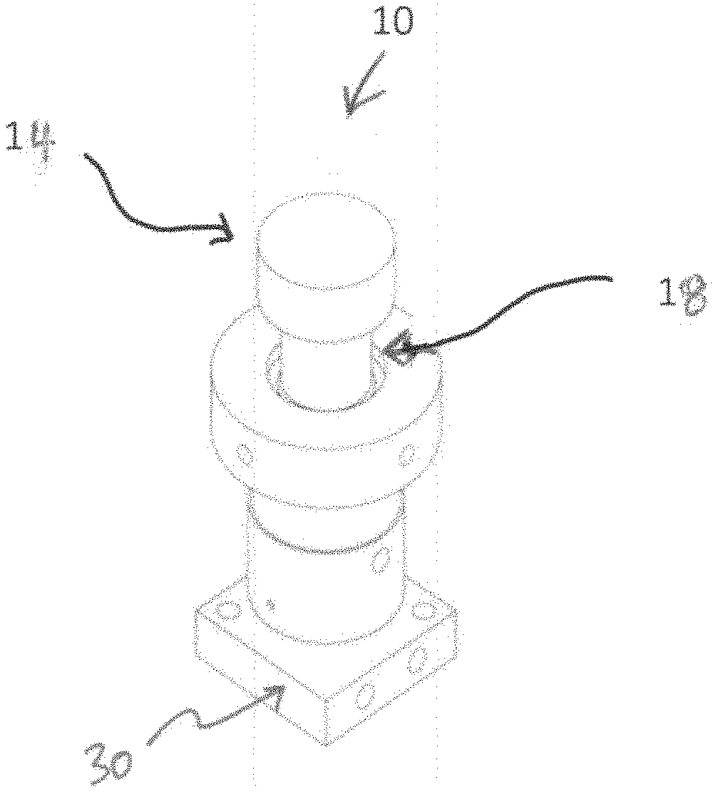
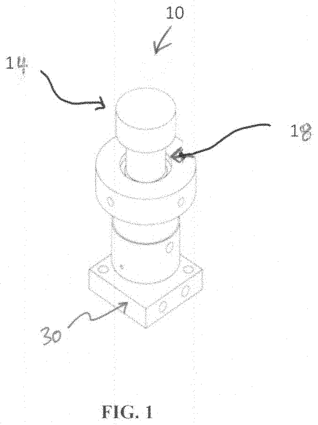
[0011] FIG. 1 is a perspective view of an illustrative thermionic energy converter.
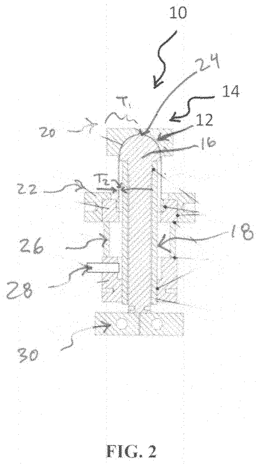
[0012] FIG. 2 is a side plan view in cutaway of the thermionic energy converter of FIG. 1.
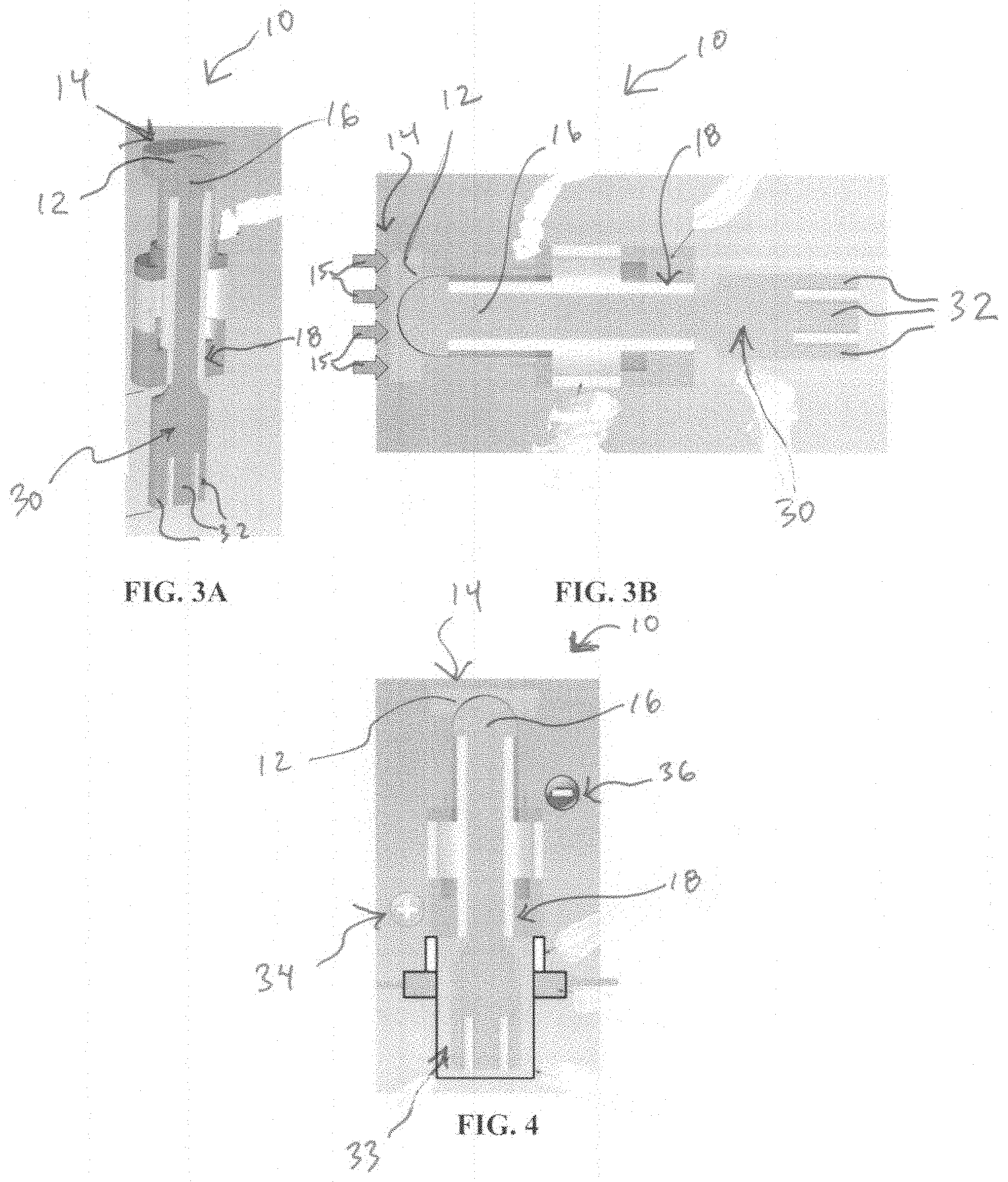
[0013] FIG. 3A is a perspective view in cutaway of the thermionic energy converter of FIG. 1.
[0014] FIG. 3B is another side plan view in cutaway of the thermionic energy converter of FIG. 1.
[0015] FIG. 4 is a side plan view in cutaway showing details regarding electrical connections in the thermionic energy converter of FIG. 1.
[0016] FIG. 5 illustrates thermal modeling of the thermionic energy converter of FIG. 1.
[0017] FIGS. 6, 7, 8A, 8B, 9, and 10 illustrate heat transfer enhancement features.
DETAILED DESCRIPTION
[0018] In the following detailed description, reference is made to the accompanying drawings, which form a part hereof. In the drawings, similar symbols typically identify similar components, unless context dictates otherwise. The illustrative embodiments described in the detailed description, drawings, and claims are not meant to be limiting. Other embodiments may be utilized, and other changes may be made, without departing from the spirit or scope of the subject matter presented here.
[0019] By way of overview, various disclosed embodiments include thermionic energy converters with a thermal concentrating hot shell and emitters for thermionic energy converters.
[0020] Still by way of overview and referring to FIGS. 1, 2, 3A, 3B, and 4, in various embodiments an illustrative thermionic energy converter ("TEC") 10 includes an emitter electrode 12. A hot shell 14 is configured to concentrate heat flow 15 (FIG. 3B) toward the emitter electrode 12. A collector electrode 16 is provided. A cold shell 18 is thermally isolated from the hot shell 14.
[0021] Now that an overview has been provided, details will be explained by way examples provided by way of illustration only and not of limitation.
[0022] Still referring to FIGS. 1, 2, 3A, 3B, and 4, in various embodiments the thermal concentrating hot shell 14 is configured (such as being shaped) to concentrate the heat flow 15 toward the emitter electrode 12 while thermally isolating the emitter electrode 12 and the hot shell 14 from the collecting side of the TEC 10 (that is, the collector electrode 16 and the cold shell 18). In some such embodiments the emitter electrode 12 has, without limitation, a hemispherical vacuum-facing surface. It will be appreciated that in such embodiments the shape or geometry of the emitter electrode 12 can help provide increased power output per cross-sectional area compared to a flat (for example, circular or cylindrical) emitter surface. While a simple, hemispherically-shaped geometry is shown, it will be appreciated that other, more complex shapes could be used that can help contribute to providing even higher amounts of surface area within a given enclosed volume as desired for a particular application.
[0023] In various embodiments, the hot shell 14 may have a tapered shell wall design that allows heat to be concentrated on the hot, emitter side of the TEC 10 and isolated from the cold, collector side of the TEC 10. In some such embodiments the hot shell 14 has a wall thickness that tapers from a thickness T.sub.1 (FIG. 2) at an end 20 to a thickness T.sub.2 (FIG. 2) at an end 22 that is distal the emitter electrode 12. In such embodiments, the thickness T.sub.2 is less than the thickness T.sub.1. In various embodiments, wall thicknesses, lengths, and/or shape of the hot shell 14 may be selected in a manner to help balance, trade off, and seek to optimize competing design factors of thermal isolation between the hot and cold side of the TEC 10, mechanical integrity of the hot shell 14 under thermal cycling, current carrying capability of the wall of the hot shell 14, and machinability of the structure of the TEC 10.
[0024] In some embodiments the emitter electrode 12 may be made with electron emissive material such as a refractory metal, a refractory alloy, and/or a superalloy. In some such embodiments, the refractory metal and/or the refractory alloy may include materials such as, without limitation, molybdenum, tungsten, niobium, kanthal, Haynes 214, and/or a metallized ceramic. In some other such embodiments the superalloy may include materials such as FeCrCl and/or Kanthal APM. It will be appreciated that superalloys can act as electron emitters--albeit typically not as good as pure refractory metals and/or refractory alloys. It will also be appreciated that superalloys also are prone to evaporation--which may, in some instances, affect work function of the surface of the collector electrode 16.
[0025] In some embodiments the hot shell 14 may be made with a structural material and the emitter electrode 12 may include a coating of electron-emitting material on a vacuum-facing (that is, interior) surface of the hot shell 14. In some such embodiments the structural material of the hot shell 14 may include a material such steel, a superalloy, SiC, alumina, kanthal, haynes alloys, stainless, sibor, inconel, zro2, hastelloy, rene, CMCs, MMC, cermet, TiN, and/or the like. In some such embodiments the electron-emitting material of the emitter electrode 12 may include a material such as a refractory metal, a refractory alloy, a superalloy (all of which have been discussed above), and/or a mixture of a refractory metal, a refractory alloy, or a superalloy with other materials to enhance electron emission, such as without limitation barium, calcium, thorium, strontium, barium oxide, calcium oxide, thorium oxide, strontium oxide, lanthanum, lanthanum oxide, scandium oxide, vanadium oxide, a boride of lanthanum, cerium, cerium oxide, a boride of cerium, scandium, vanadium, and/or carbon.
[0026] In various embodiments, the collector electrode 16 may include a collector rod. In some such embodiments, the collector rod may be made with a material such as without limitation copper, stainless steel, steel, nickel, a refractory metal, metalized ceramic, or the like. In such embodiments the collector rod may be surrounded by a collector brazing sleeve which is used to facilitate assembly via brazing of components of the TEC 10. The brazing sleeve can be made from, without limitation, Kovar, OFE Copper 101, Stainless Steel (SST), Monel, Tungsten, Cupro-Nickel, Titanium, Aluminum, or other suitable materials.
[0027] In some embodiments the collector rod may include an alignment-and-gap-setting feature 24 (FIG. 2) that is configured to set a gap between the vacuum-facing surface of the emitter electrode 12 and a vacuum-facing surface of the collector electrode 16. In such embodiments the alignment and gap setting feature 24 sets the gap between surfaces of the emitter electrode 12 and the collector electrode 16 when the assembly is brazed together. It will be appreciated that thermal expansion of metal components may contribute to further changes in the gap and may contribute to isolating the alignment and gap setting feature 24 from the vacuum-facing surface of the emitter electrode 12. Gap widths can be in a range of tens of microns to hundreds of microns depending upon properties of the emitter electrode 12 and the collector electrode 16 and the gas or vapor mixture in the gap.
[0028] In various embodiments an electrical isolator 26 (FIG. 2) is configured to electrically isolate the collector electrode 16 from the emitter electrode 12. In some such embodiments the electrical isolator 26 may include a ceramic breaker ring. In some such embodiments the ceramic breaker ring may be made from alumina, silicon nitride, silicon carbide, or other suitable high temperature ceramic material as desired for a particular application.
[0029] In various embodiments a port 28 (FIG. 2) is configured to evacuate the thermionic energy converter. In some such embodiments the port 28 may be further configured to fill the thermionic energy converter with material selected to increase electron emission of the emitter electrode 12 and lower work function of the collector electrode 16. For example, in some such embodiments a metal tube, made from a nickel-cobalt ferrous alloy (such as Kovar) or other suitable material, is used to provide the port 28 for evacuating the TEC 10 and for dosing the TEC 10 with Cs or CsOx to enhance the performance of the TEC 10 via increasing the electron emission of the surface of the emitter electrode 12 and by lowering the work function of the collector electrode 16.
[0030] In various embodiments a heat exchanger (or heat sink) 30 is disposed in thermal communication with the cold shell 18 at an end of the cold shell 18 that is distal the emitter electrode 12. In such embodiments the heat exchanger 28 terminates at the end of the collector rod to pull heat away from the TEC 10 and thereby forming an extended heat sink. In some such embodiments the heat exchanger 30 may include fins or other structures 32 (FIGS. 3A and 3B).
[0031] In various embodiments and as shown in FIG. 4, a thermal interface material 33 (electrically insulating or conducting) with appropriate thermal conductivity may be used to transfer heat at a desired amount from the cold shell 18 to the heat exchanger 30. The thermal interface material 33 may also be a piece of material (such as without limitation copper or other highly thermally conductive metals, thermally conductive metal alloys, thermally conductive ceramic, or the like). In some embodiments a heat pipe may also be used. The heat pipe could be filled with a fluid, a mixture of fluids (water and glycol, for instance, or organic fluids like methanol or ethanol or napthalene), or a metal (cesium, potassium, sodium, mercury, or a mixture thereof). The inside wall of the heat pipe may be grooved, or covered with a mesh, wire, screen, or a sintered material, as desired. The cold shell 18 may also include divots or other machined shapes to conform closely to the heat exchanger 30 or accommodate the form factor of the heat exchanger 30 for mechanical stability, for better thermal contact, or for optimizing transfer of heat from the cold shell 18 to the heat exchanger 30. A thermal grease (such as without limitation metal like silver paste, organic, or graphite) may be used to enhance thermal contact between the cold shell 18 and the heat exchanger 30.
[0032] In various embodiments the TEC 10 may suitably be integrated into existing space in, around, or between burner sections of gas heaters and a heat exchanger. For example, in some such embodiments the heat exchanger 28 suitably may terminate into a heat exchanger of a gas furnace (not shown) or to walls of a water tank or boiler (not shown). When provided, the fins or other structures 32 may directly transfer heat to fluid or air (such as water in a boiler or air in a furnace).
[0033] As shown in FIG. 4, in various embodiments appropriate electrical contacts are attached to the TEC 10. For example, a positive electrical terminal 34 is electrically connected to the collector electrode 16 and a negative electrical terminal 36 is electrically connected to the emitter electrode 12. In some such embodiments, the negative electrical terminal 36 is electrically connected to the emitter electrode 12 at an isothermal temperature point between the hot shell 14 and the cold shell 18. By doing so, heat transfer can be reduced (with a goal of seeking to be minimized) between neighboring series cells (sometimes referred to as "lead loss") in series cell TECs.
[0034] In various embodiments, the leads between the cells of a series cell TEC can be fashioned from suitable high temperature/heavy gauge wires or mineral insulated cables. In some embodiments, pure metal bus bars may also be used if desired. The type of leads and connects between cells may be determined in part by the current carrying requirements between the cells and between groups of cells connected in series-parallel arrangements. The temperature at the various contact points may also be considered as well as the cost of various lead materials.
[0035] In various embodiments the non vacuum-facing surface of the hot shell 14 may be coated with a coating selected to reduce NO.sub.x emission. In such embodiments a coating is added to the surface of the non vacuum-facing surface of the hot shell 14 that could help reduce NO.sub.x emission by breaking down the NO.sub.x into N.sub.2 and O.sub.2. As is known, many metal coatings and composite metals are known to provide catalytic properties toward NO.sub.x breakdown. For instance, selective or non-selective catalytic reduction of NO.sub.x and/or sorption-type materials may be used as desired for a particular application.
[0036] Referring additionally to FIG. 5, thermal analysis shows thermal concentration properties of an illustrative TEC 10. As shown in FIG. 5, in various embodiments heat is concentrated near the hemispherical vacuum-facing surface of the emitter electrode 12.
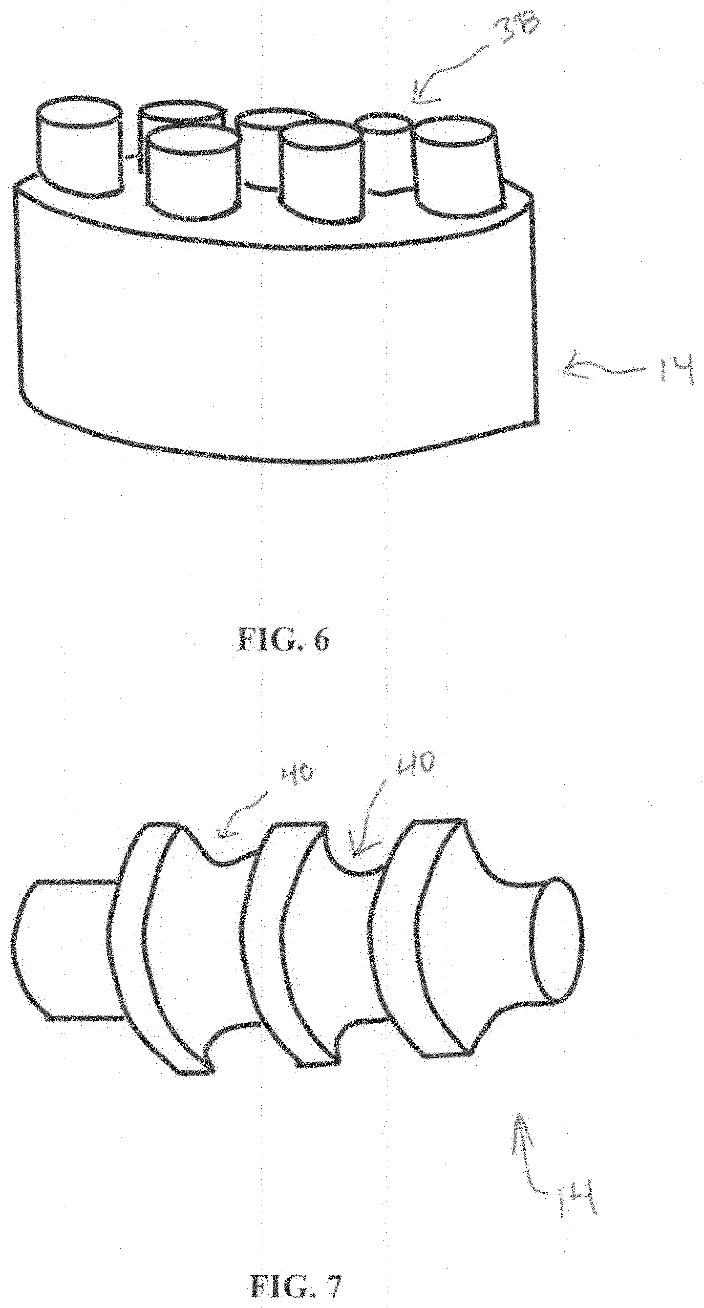
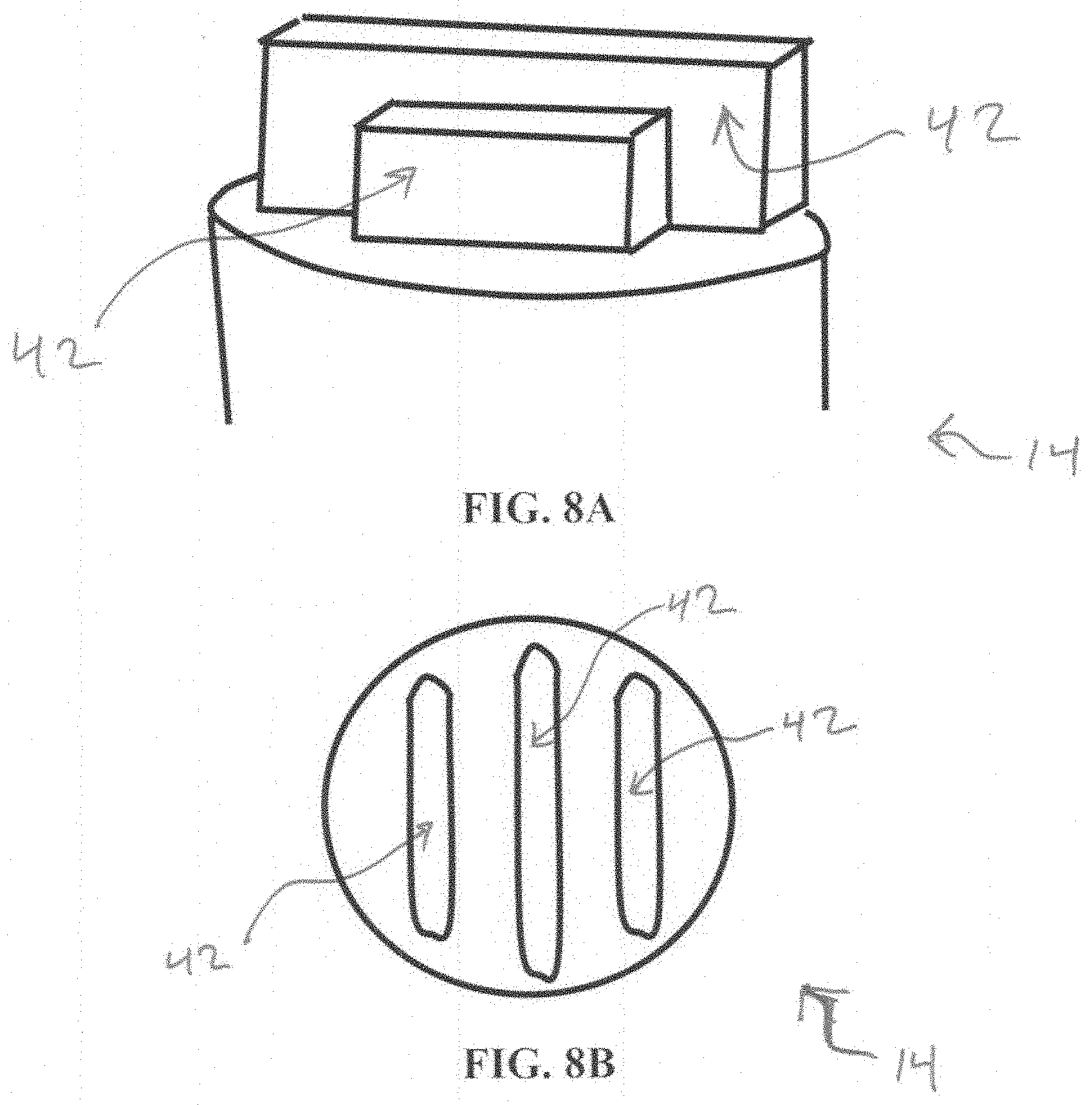
[0037] To improve heat transfer into the TEC 10, in various embodiments geometry of the hot shell 14 can be designed to increase convective and radiative heat transfer. Referring additionally to FIGS. 6, 7, 8A, 8B, 9, and 10, in various embodiments the hot shell 14 may include a heat transfer enhancement feature. Given by way of non-limiting examples, the heat transfer enhancement feature may include pins 38 (FIG. 6), grooves 40 that are defined in a non-vacuum-facing surface of the hot shell 14 (FIG. 7), at least one extension 42 (FIGS. 8A, 8B, and 9), and a faceted geometry FIG. 10) defined in the non-vacuum-facing surface of the hot shell 14.
[0038] As shown in FIG. 6, in some embodiments a bank of pins 38 may be placed on the hot shell 14 to increase the convection area. In such embodiments the pins 38 can help to improve heat transfer to the TEC 10 from a heat source (such as a flame from burning fuel).
[0039] As shown in FIG. 7, in some embodiments circumferential features or grooves 40 may be defined in a non-vacuum-facing surface of the hot shell 14. In such embodiments the grooves 40 can help to enhance convective heat transfer aligned with the flow of heated air or combustion gases with less pressure drop through the system.
[0040] As shown in FIGS. 8A and 8B, in some embodiments fins or extensions 42 may be aligned with the flow heat air of flame gases. In such embodiments the extensions 42 can help to increase heat transfer while maintaining low pressure drop through the system.
[0041] As shown in FIG. 9, in some embodiments the extensions 42 from the hot shell 14 can form passages for increased velocity and heat transfer TECs 10 are assembled in an array of multiple TECs 10 that is placed in the heat flow from burning gas.
[0042] As shown in FIG. 10, in some embodiments the hot shell 14 may define a faceted geometry to reflect re-radiation to other TECs 10 and to help avoid the burner. This feature can help reduce radiation losses of the hot shell 14 and can help contribute to improving burner life.
[0043] While various aspects and embodiments have been disclosed herein, other aspects and embodiments will be apparent to those skilled in the art. The various aspects and embodiments disclosed herein are for purposes of illustration and are not intended to be limiting, with the true scope and spirit being indicated by the following claims.
* * * * *
D00000
D00001
D00002
D00003
D00004
D00005
D00006
D00007
XML
uspto.report is an independent third-party trademark research tool that is not affiliated, endorsed, or sponsored by the United States Patent and Trademark Office (USPTO) or any other governmental organization. The information provided by uspto.report is based on publicly available data at the time of writing and is intended for informational purposes only.
While we strive to provide accurate and up-to-date information, we do not guarantee the accuracy, completeness, reliability, or suitability of the information displayed on this site. The use of this site is at your own risk. Any reliance you place on such information is therefore strictly at your own risk.
All official trademark data, including owner information, should be verified by visiting the official USPTO website at www.uspto.gov. This site is not intended to replace professional legal advice and should not be used as a substitute for consulting with a legal professional who is knowledgeable about trademark law.