Small Form Factor Fiber Optic Connector With Resilient Latching Mechanism For Securing Within A Hook-less Receptacle
GNIADEK; Jeffrey ; et al.
U.S. patent application number 16/853571 was filed with the patent office on 2020-10-22 for small form factor fiber optic connector with resilient latching mechanism for securing within a hook-less receptacle. This patent application is currently assigned to Senko Advanced Components, Inc.. The applicant listed for this patent is Senko Advanced Components, Inc.. Invention is credited to Jimmy CHANG, Jeffrey GNIADEK.
| Application Number | 20200333537 16/853571 |
| Document ID | / |
| Family ID | 1000004810108 |
| Filed Date | 2020-10-22 |


View All Diagrams
| United States Patent Application | 20200333537 |
| Kind Code | A1 |
| GNIADEK; Jeffrey ; et al. | October 22, 2020 |
SMALL FORM FACTOR FIBER OPTIC CONNECTOR WITH RESILIENT LATCHING MECHANISM FOR SECURING WITHIN A HOOK-LESS RECEPTACLE
Abstract
A small form factor optical connector holding two or more LC-type optical ferrules is provided. The optical connector includes an outer body, an inner front body accommodating the two or more LC-type optical ferrules, a pair a resilient latches and corresponding recess for the resilient latch, ferrule springs for urging the optical ferrules towards a mating receptacle, and a back body for supporting the ferrule springs. The outer body and the inner front body are configured such that four LC-type optical ferrules are accommodated in a small form-factor pluggable (SFP) transceiver footprint or eight LC-type optical ferrules are accommodated in a quad small form-factor pluggable (QSFP) transceiver footprint. A mating receptacle (transceiver or adapter) includes a receptacle hook and a housing with an opening that accommodates the receptacle hook in a flexed position as the optical connector makes connection with the mating receptacle by introducing the receptacle hook into an optical receptacle hook recess.
| Inventors: | GNIADEK; Jeffrey; (Oxford, ME) ; CHANG; Jimmy; (Worcester, MA) | ||||||||||
| Applicant: |
|
||||||||||
|---|---|---|---|---|---|---|---|---|---|---|---|
| Assignee: | Senko Advanced Components,
Inc. Marlborough MA |
||||||||||
| Family ID: | 1000004810108 | ||||||||||
| Appl. No.: | 16/853571 | ||||||||||
| Filed: | April 20, 2020 |
Related U.S. Patent Documents
| Application Number | Filing Date | Patent Number | ||
|---|---|---|---|---|
| 62836155 | Apr 19, 2019 | |||
| Current U.S. Class: | 1/1 |
| Current CPC Class: | G02B 6/3893 20130101; G02B 6/3825 20130101; G02B 6/3826 20130101 |
| International Class: | G02B 6/38 20060101 G02B006/38 |
Claims
1. A small form factor connector for holding two or more LC-type optical ferrules, comprising: an outer housing having a longitudinal bore; at least one inner front body removably received in the outer housing longitudinal bore, the inner front body supporting two LC-type optical ferrules, the inner front body further comprising top and bottom portions, the top and bottom portions are configured to accept a resilient latch.
2. The small form factor connector for holding two or more LC-type optical ferrules according to claim 1, wherein the top portion and the bottom portion further comprise a recess to accept a portion of the resilient latch.
3. The small form factor connector for holding two or more LC-type optical ferrules according to claim 2, wherein the resilient latch protrudes through an opening formed proximally in the outer housing.
4. The small form factor connector for holding two or more LC-type optical ferrules according to claim 3, wherein the proximal opening in the outer housing is angled.
5. The small form factor connector for holding two or more LC-type optical ferrules according to claim 4, wherein the angle of the proximal opening is less than ninety (90) degrees relative to a normal formed with the longitudinal bore.
6. The small form factor connector for holding two or more LC-type optical ferrules according to claim 1, wherein the inner front body top and bottom portions further comprises partially open sidewalls.
7. The small form factor connector for holding two or more LC-type optical ferrules according to claim 1, wherein a receptacle port does not contain a snap-in hook assembly to secure the small form factor connector within the receptacle port.
8. The small form factor connector for holding two or more LC-type optical ferrules according to claim 6, wherein the resilient latch secures the small form factor connector within a receptacle port when the resilient latch protrudes through an opening in a top wall portion or a bottom wall portion of a receptacle outer housing.
9. The small form factor connector for holding two or more LC-type optical ferrules according to claim 6, wherein a backpost-spring pusher is configured to secure to a distal end of the inner front body, and further wherein the inner front body is configured to accept the two or more LC-type optical ferrules each biased by a ferrule spring when the backpost-spring pusher is secured to the inner front body by a pair of opposing latch hooks within a pair of openings formed at a distal end of the inner front body thereby forming, an inner front body assembly.
10. The small form factor connector for holding two or more LC-type optical ferrules according to claim 9, wherein the inner front body assembly is secured within the outer housing.
11. The small form factor connector for holding two or more LC-type optical ferrules according to claim 10, wherein a push/pull boot is secured to a distal end of the outer housing thereby securing the inner front body within the outer housing, and further wherein the push/pull boot is configured to release the small form factor connector from the receptacle port when the push/pull boot is pulled rearward.
12. The small form factor connector for holding two or more LC-type optical ferrules according to claim 11, wherein pulling the push/pull hoot rearward, the outer housing slides over resilient latch retracting the resilient latch from the opening in the receptacle outer housing thereby allowing the small form factor connector to be removed from the receptacle port.
13. The small form factor connector for holding two or more LC-type optical ferrules according to claim 12, wherein the push/pull boot is used to secure the small form factor connector in the receptacle port when the push/pull boot is pushed in a forward direction thereby allowing the resilient latch to return to its original position and protrude through the receptacle outer housing opening once the small form factor connector is fully inserted into the receptacle port.
14. The small form factor connector for holding two or more LC-type optical ferrules according to claim 13, wherein a leading edge of the receptacle outer housing depresses the resilient latch as the small form factor connector is inserted into the receptacle port.
15. An inner front body assembly, comprising: a main body with opposing top portion and bottom portion; a latch hole formed nearer a distal end of the top portion and the bottom portion, the latch hole is configured to accept a corresponding latch hook on a main body of a backpost-spring pusher thereby securing two or more LC-type optical ferrules within the inner front body; and wherein a pair of opposing recesses nearer a proximal end of the top portion and the bottom portion, the recesses are configured to accept a resilient latch.
16. The inner front body assembly according to claim 15, wherein the two or more LC-type optical ferrules are biased forward within the inner front body by a ferrule spring.
17. The inner front body assembly according to claim 15, wherein the inner front body assembly is secured within an outer housing, the outer housing further comprises a pair of opposing openings through which the resilient latch protrudes when the inner front hoot is secured within the outer housing.
18. The inner front body assembly according to claim 17, where the outer housing has a pair of opposing openings nearer a distal end of the housing, the openings accept a pair of opposing boot latches thereby securing the inner front body assembly within the outer housing.
19. The small firm factor connector for holding two or more LC-type optical ferrules according to claim 1, where the resilient latch is formed from a metal or a plastic.
20. The inner front body assembly according to claim 15, wherein the resilient latch is formed from a metal or a plastic.
Description
CROSS-REFERENCE TO RELATED APPLICATIONS
[0001] The present application claims the benefit of priority under 35 U.S.C. 119(e) to the filing date of U.S. Provisional Patent Application 62/836,155 filed Apr. 19, 2019, titled, "SMALL FORM FACTOR FIBER OPTIC CONNECTOR WITH RESILIENT LATCHING MECHANISM FOR SECURING TO RECEPTACLE", The contents of which is fully incorporated herein by reference in its entirety.
FIELD OF THE INVENTION
[0002] The present disclosure relates generally to ultra-small form factor optical connectors secured with an adapter or optical transceiver both generally called a receptacle.
BACKGROUND
[0003] The prevalence of the Internet has led to unprecedented growth in communication networks. Consumer demand for service and increased competition has caused network providers to continuously find ways to improve quality of service while reducing cost.
[0004] Certain solutions have included deployment of high-density interconnect panels. High-density interconnect panels may be designed to consolidate the increasing volume of interconnections necessary to support the fast-growing networks into a compacted form factor, thereby increasing quality of service and decreasing costs such as floor space and support overhead. However, room for improvement in the area of data centers, specifically as it relates to fiber optic connections, still exists: For example, manufacturers of connectors and adapters are always looking to reduce the, size of the devices, while increasing ease of deployment, robustness, and modifiability after deployment. In particular, more optical connectors may need to be accommodated in the same footprint previously used for a smaller number of connectors in order to provide backward compatibility with existing data center equipment. For example, one current footprint is known as the small form-factor plug able transceiver footprint (SFP). This footprint currently accommodates two LC-type ferrule optical connections. However, it may be desirable to accommodate four optical connections (two duplex connections of transmit/receive) within the same footprint. Another current footprint is the quad small form-factor pluggable (QSFP) transceiver footprint. This footprint currently accommodates four LC-type ferrule optical connections. However, it may be desirable to accommodate eight optical connections of LC-type ferrules (four duplex connections of transmit/receive) within the same footprint.
[0005] In communication, networks, such as data centers and switching networks, numerous interconnections between mating connectors may be compacted into high-density panels. Panel and connector producers may optimize for such high densities by shrinking the connector size and or the spacing between adjacent connectors on the panel. While both approaches may be effective to increase the panel connector density, shrinking the connector size and/or spacing may also increase the support cost and diminish the quality of service.
[0006] In a high-density panel configuration, adjacent connectors and cable assemblies may obstruct access to the individual release mechanisms. Such physical obstructions may impede the ability of an operator to minimize the stresses applied to the cables and the connectors. For example, these stresses may be applied when the user reaches into a dense group of connectors and pushes aside surrounding optical fibers and connectors to access an individual connector release mechanism with his/her thumb and forefinger. Overstressing the cables and connectors may produce latent defects, compromise the integrity and/or reliability of the terminations, and potentially cause serious disruptions to network performance.
[0007] While an operator may attempt to use a tool, such as a screwdriver, to reach into a dense group of connectors and activate a release mechanism, adjacent cables and connectors may obstruct the operator's line of sight, making it difficult to guide the tool to the release mechanism without pushing aside the adjacent cables. Moreover, even when the operator has a clear line sight, guiding the tool to the release mechanism may be a time-consuming process. Thus, using a tool may not be effective at reducing support time and increasing the quality of service.
SUMMARY OF THE INVENTION
[0008] An optical connector holding a ferrule assembly the assembly may contain two or more LC-type optical ferrules or a single optical ferrule, basis with a spring, and each ferrule having one or more optical fiber therein is provided. The optical connector includes an outer body, an inner front body accommodating the optical ferrule assembly, the inner front body has open sidewalls, resilient metal latches configured to be secured between the inner front body and outer housing, ferrule springs for urging the optical ferrules and flanges within the inner body, and a back body for supporting the ferrule springs. The outer body and the inner front body are configured such that four LC-type optical ferrules are accommodated in a small form-factor pluggable (SFP) transceiver footprint or eight LC-type optical ferrules are accommodated in a quad small form-factor pluggable (QSFP) transceiver footprint. A mating receptacle (transceiver or adapter) includes does not have an internal receptacle hook configured, as in U.S. Pat. No. 10,281,669B2 to Takano the subject matter of which is fully incorporated herein by reference, and an outer housing with an opening that accommodates the receptacle hook in a flexed position as the optical connector makes connection with the mating receptacle by introducing the receptacle hook into a receptacle hook recess.
[0009] Other aspects and features will be apparent hereinafter.
BRIEF DESCRIPTION OF THE DRAWINGS
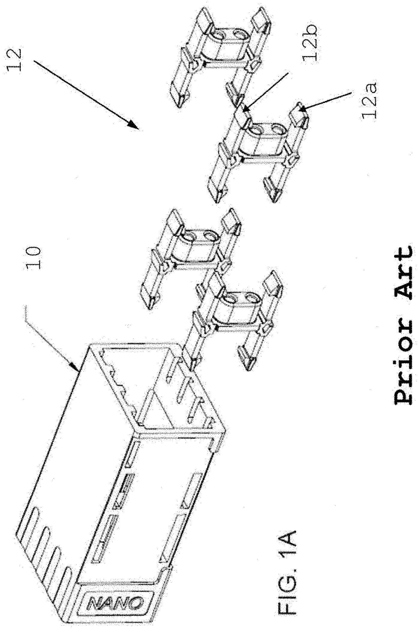
[0010] FIG. 1A is a prior art exploded view of an adapter assembly;
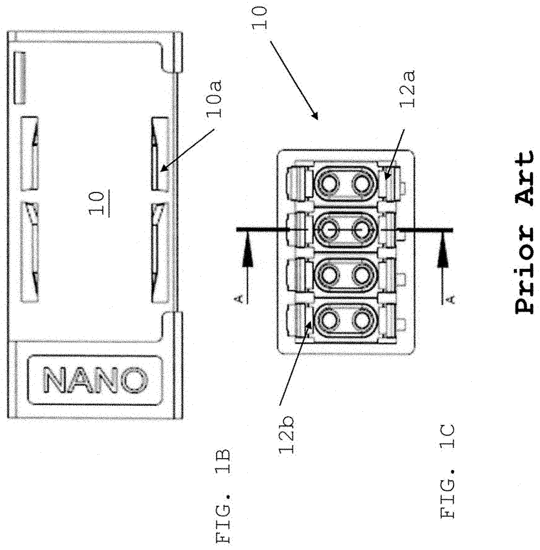
[0011] FIG. 1B is a perspective side view of an adapter of FIG. 1A;
[0012] FIG. 1C is a front view of an adapter of FIG. 1A;
[0013] FIG. 1D.1 is a cross-section view along section line A-A of snap-in hooks secured within the adapter of FIG. 1A;
[0014] FIG. 1D.2 is a zoomed view of a snap-in hook secured within the adapter port;
[0015] FIG. 1D.3 is side view of a snap-in hook;
[0016] FIG. 2A is an exploded view of a small form factor connector with a latch recess formed as part of the inner housing configured to be secured within the adapter assembly of FIG. 1A;
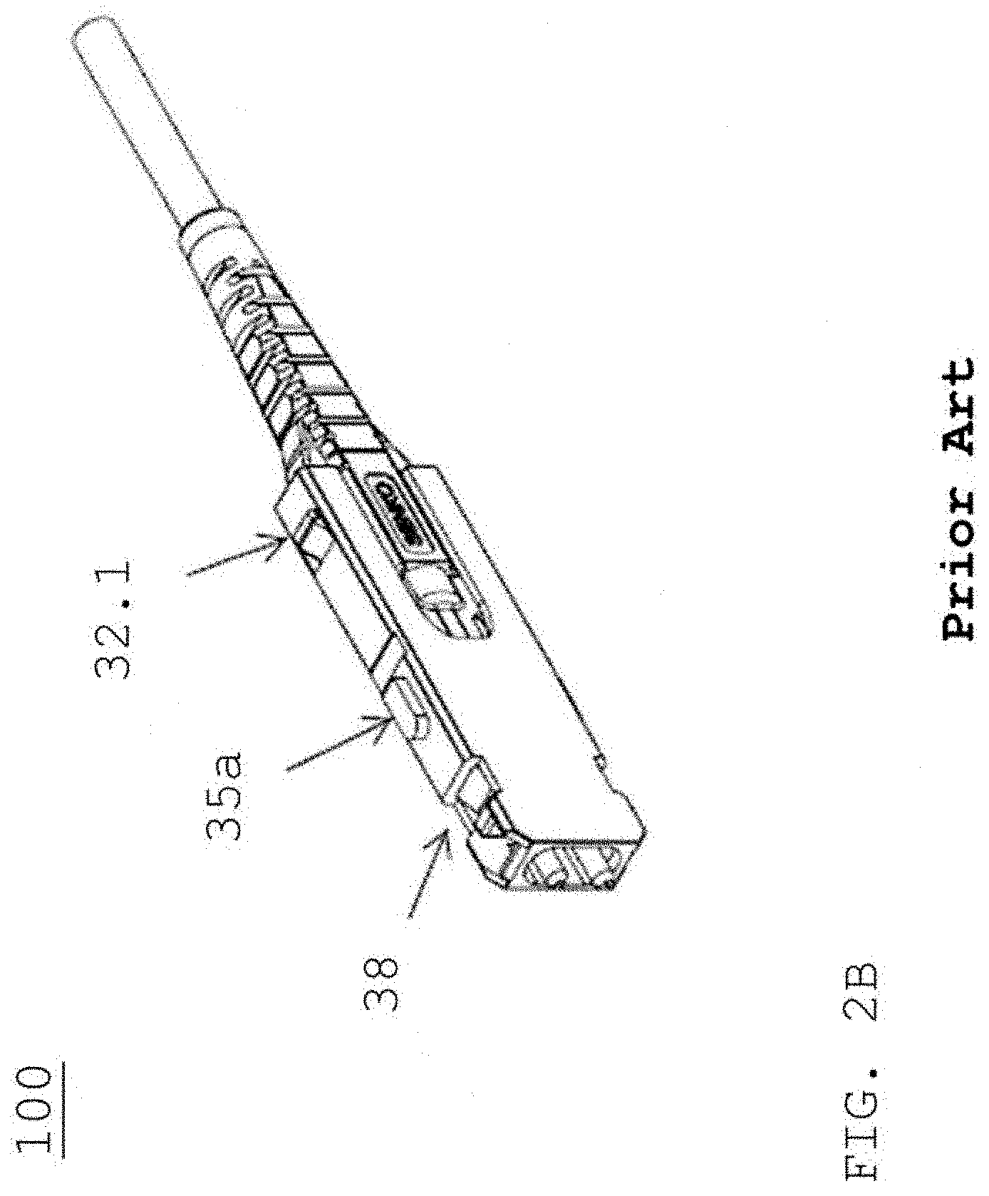
[0017] FIG. 2B is a perspective view of the FIG. 2A small form connector with a push-pull boot release;
[0018] FIG. 3A is a perspective side view of a small form factor connector and housing;
[0019] FIG. 3B is a perspective angled view of a small form factor connector and housing;
[0020] FIG. 3C is a front view of FIG. 3B assembled;
[0021] FIG. 3D is a cross section view along section line B-B of a small form connector;
[0022] FIG. 4A is a cross section view along section line C-C of an assembled inner front body with a ferrule assembly;
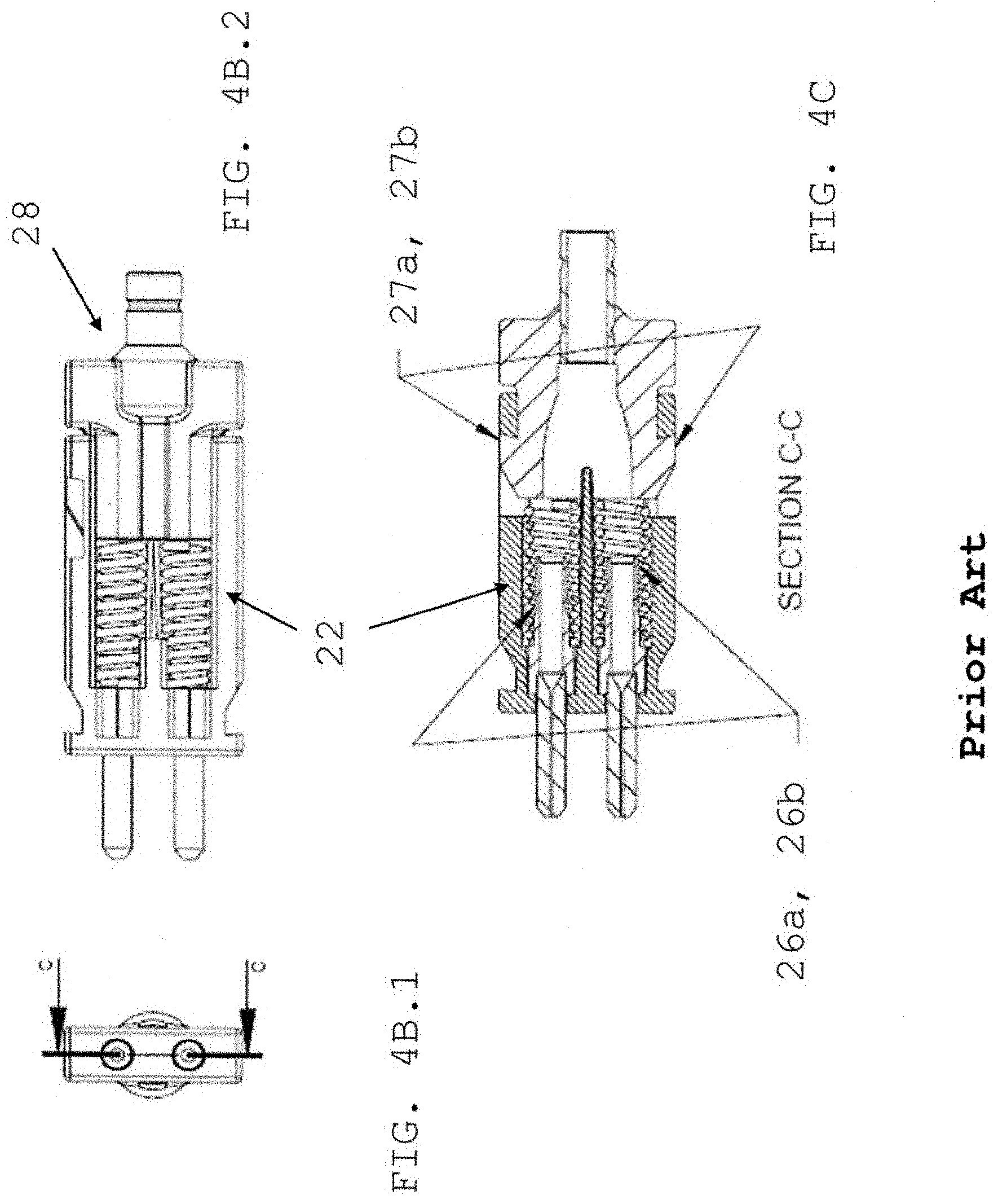
[0023] FIG. 4B.1 is a front view of FIG. 4A along section line A-A;
[0024] FIG. 4B.2 is a side view of FIG. 4B.1;
[0025] FIG. 4C is a cross-section view along section line C-C of FIG. 4B.1;
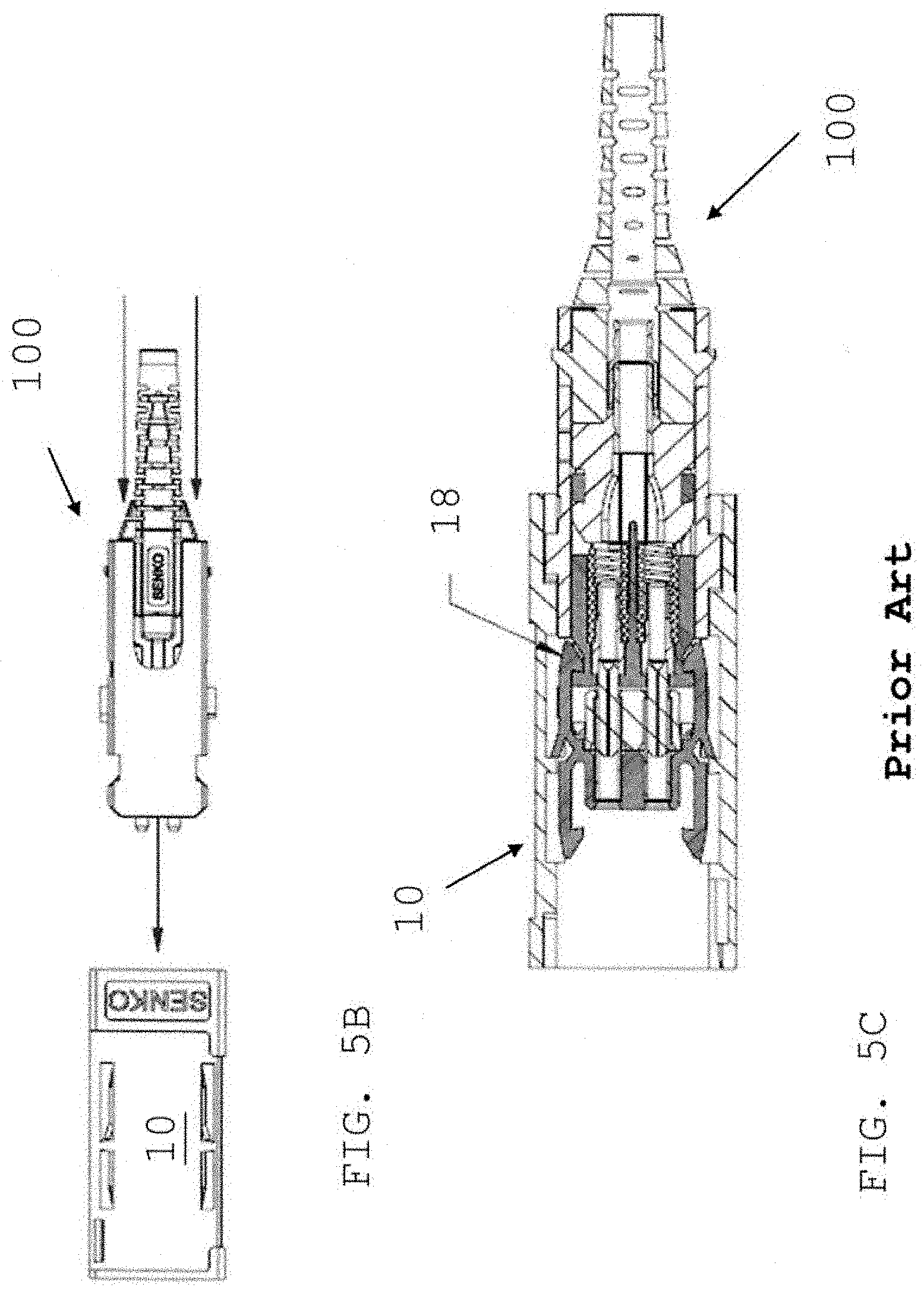
[0026] FIG. 5A is an exploded view prior to inserting the small form factor connector into the adapter port with latch hooks;
[0027] FIG. 5B is a side view of inserting the small form factor connector into the adapter port using the push/pull boot;
[0028] FIG. 5C is a cross-section view of the small form factor connector secured or latched within the adapter;
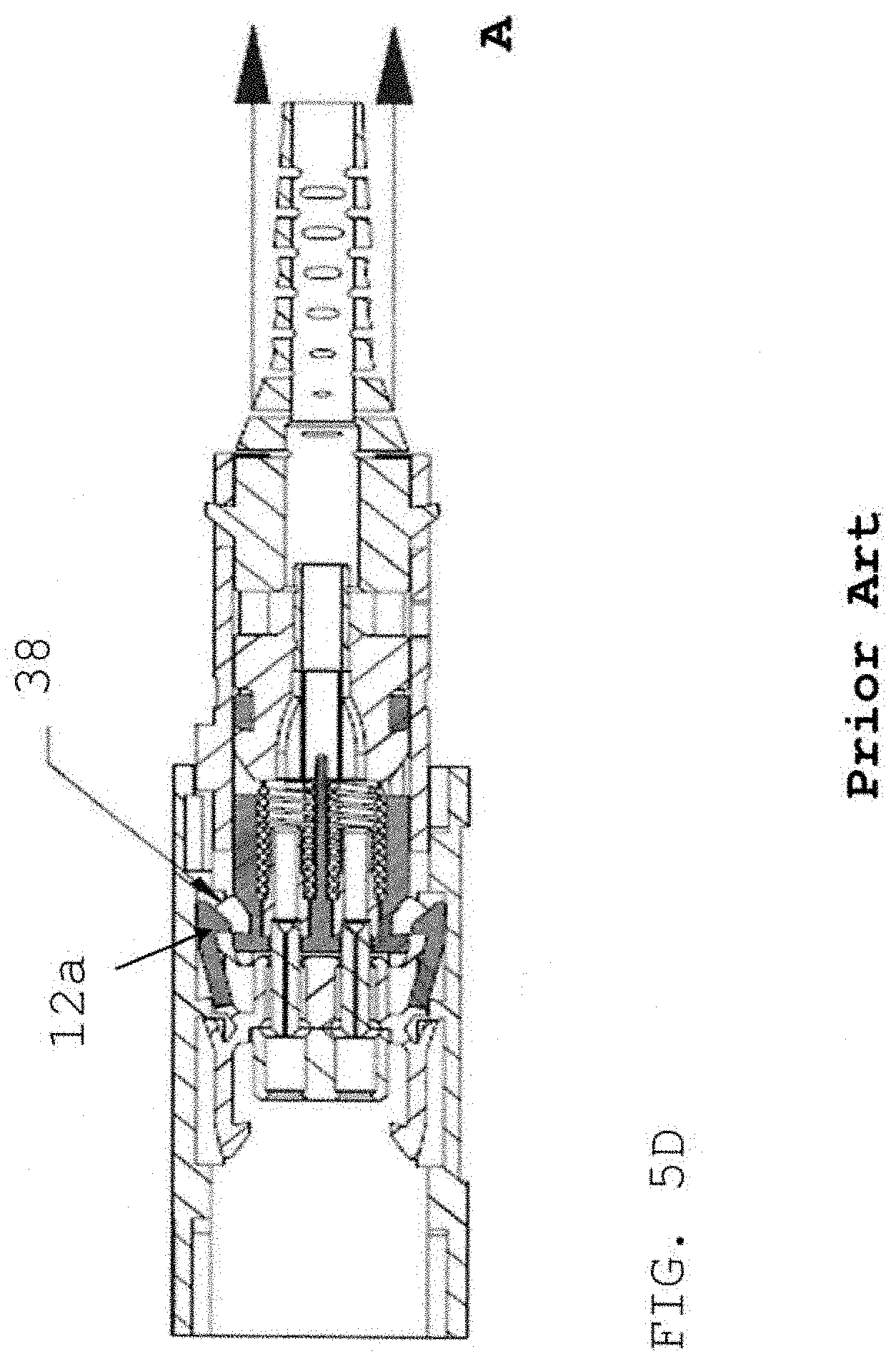
[0029] FIG. 5D is across-section view of the small form factor connector release from the adapter;
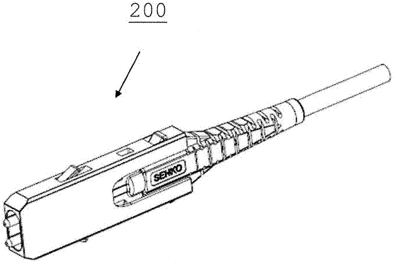
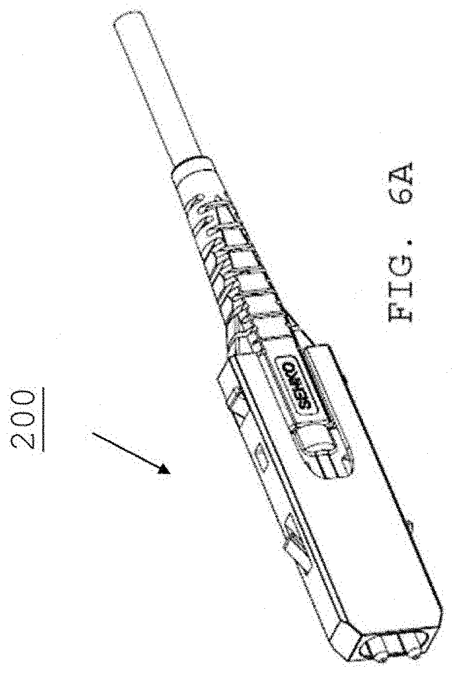
[0030] FIG. 6A is a perspective view of a small farm factor connector according to an embodiment of the present invention;
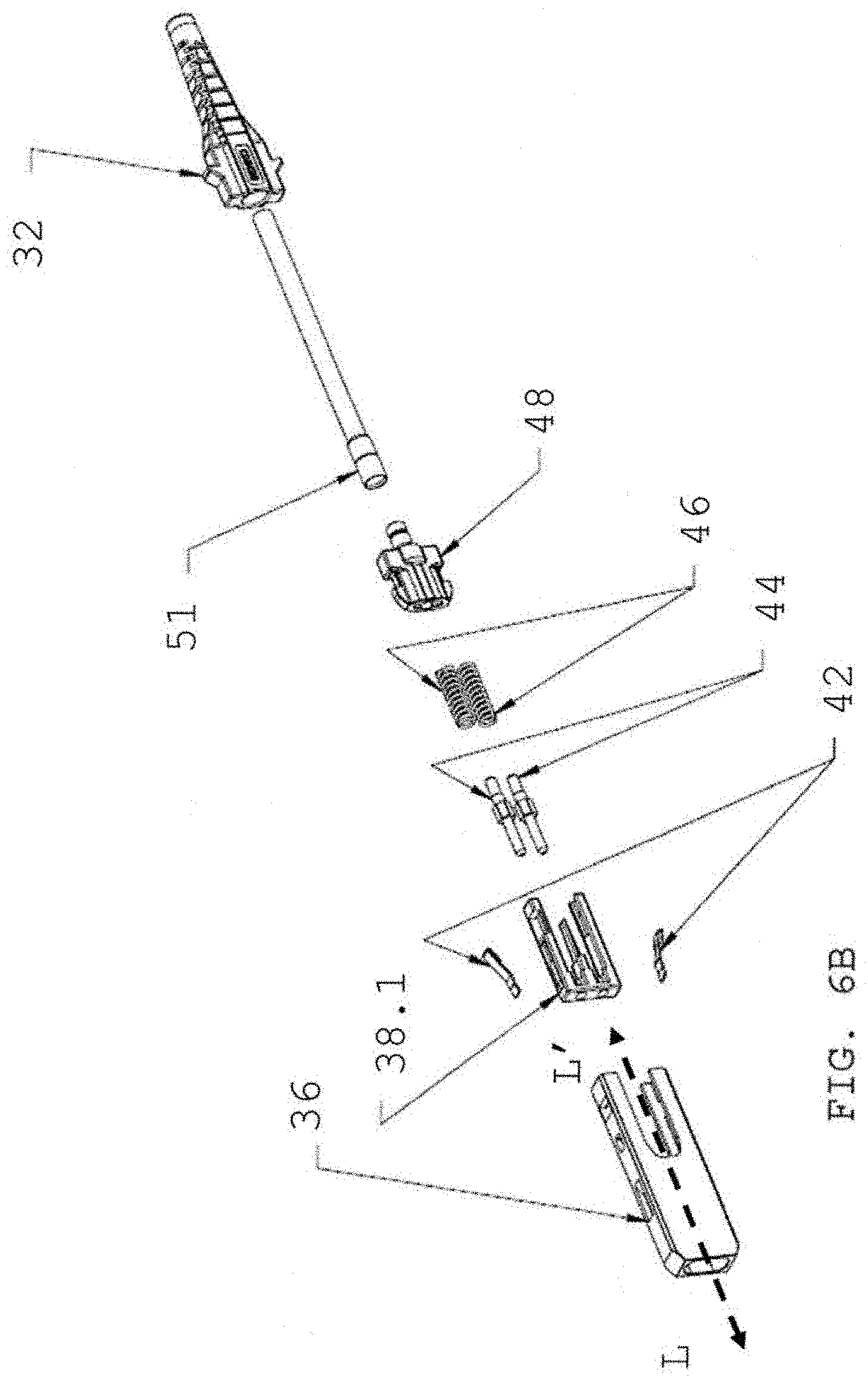
[0031] FIG. 6B is an exploded view of FIG. 6A;
[0032] FIG. 7A is side view of connector housing and boot of the FIG. 6A connector;
[0033] FIG. 7B is a front, side view of FIG. 7A;
[0034] FIG. 7C is a front view of FIG. 7A assembled with section line A-A;
[0035] FIG. 7D is a cross-section view along section line A-A of FIG. 7C;
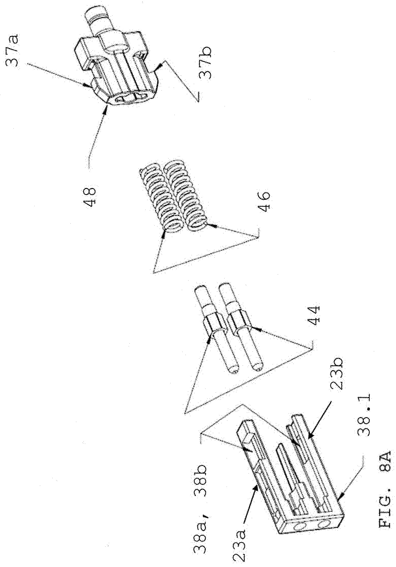
[0036] FIG. 8A is an exploded view of inner sub-assembly of connector of FIG. 10A without resilient metal latches;
[0037] FIG. 8B is front, side view of FIG. 8A assembled along line B-B;
[0038] FIG. 8C is a side view of FIG. 8A assembled;
[0039] FIG. 8D is a cross-section along line B-B of FIG. 8B;
[0040] FIG. 9A is an exploded view of the connector of FIG. 10A with resilient metal latches;
[0041] FIG. 9B is a zoomed view of FIG. 9A inner front body with resilient metal latches;
[0042] FIG. 9C is an exploded view of FIG. 10A with resilient metal latches;
[0043] FIG. 9D is an assembled view of FIG. 10A;
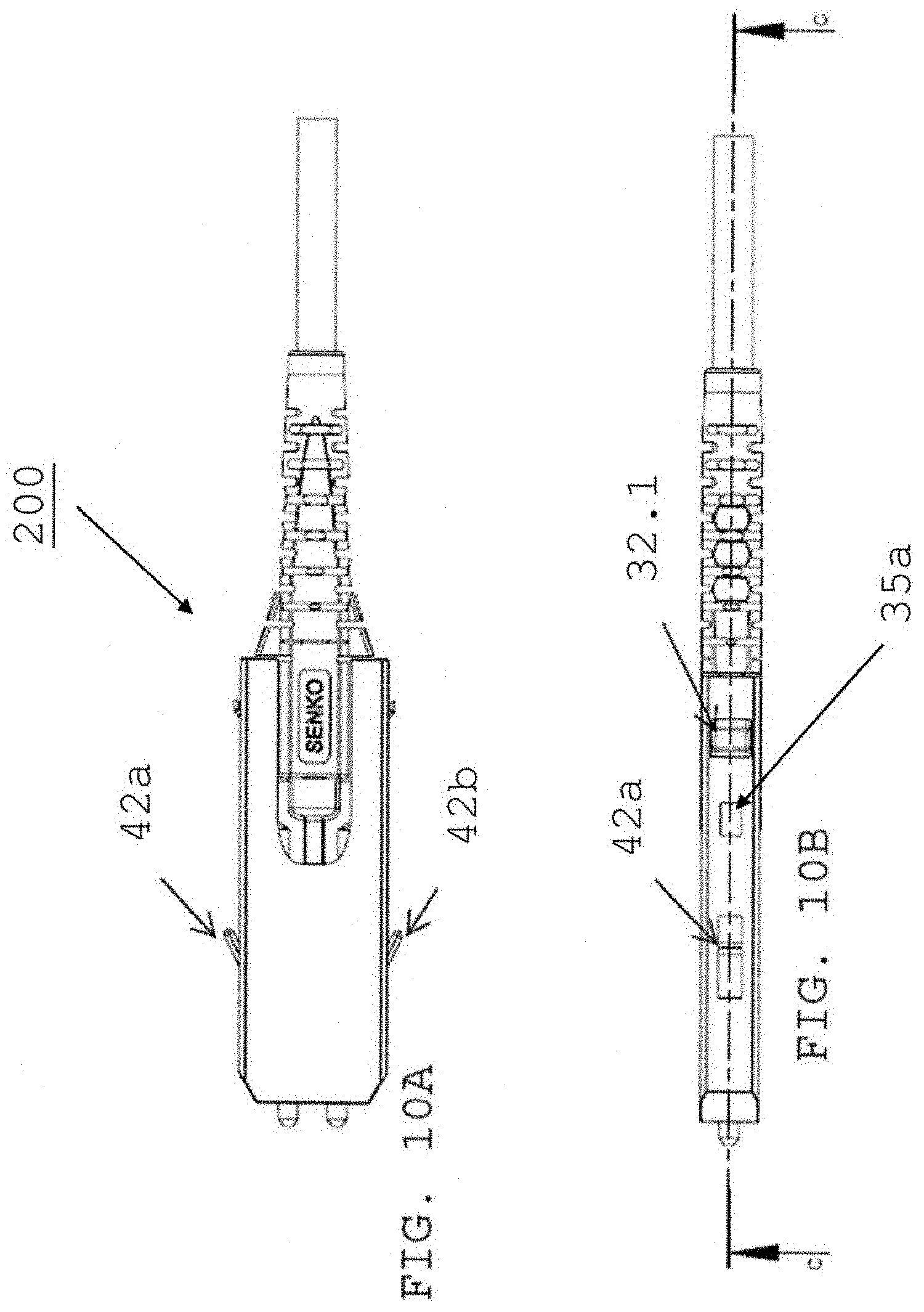
[0044] FIG. 10A is a side view of the FIG. 9D;
[0045] FIG. 10B is a top view of FIG. 10A with line C-C;
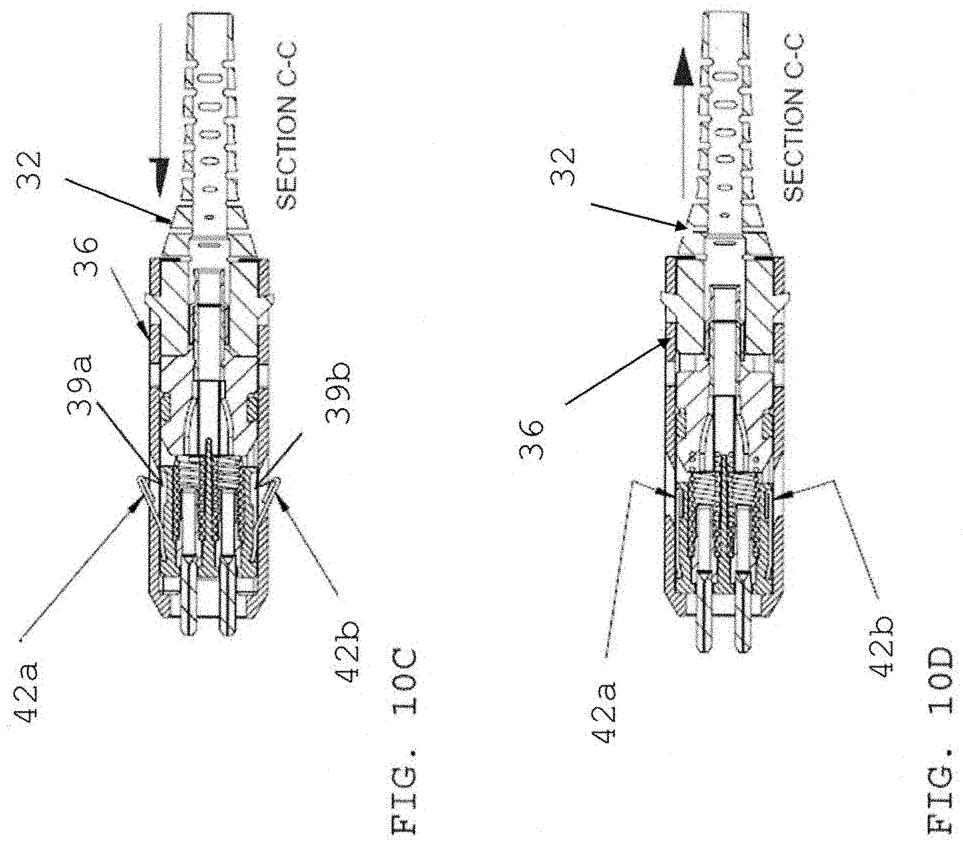
[0046] FIG. 10C is a cross-section view along section line C-C of FIG. 10B in a first configuration;
[0047] FIG. 10D is a cross-section view along section line CS-C of FIG. 10B in a second configuration;
[0048] FIG. 11A is an exploded view of a hook-less adapter and small form factor connector of FIG. 10 prior to insertion into an adapter port;
[0049] FIG. 11B is an exploded, side view of FIG. 11A;
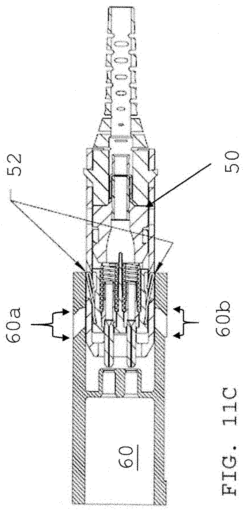
[0050] FIG. 11C is a cross section view of a partial insertion of the connector of FIG. 10A into a hook-less adapter;
[0051] FIG. 12 is a cross section of view the connector of FIG. 10A fully inserted (PI) via the push/pull hoot into a hook-less adapter port;
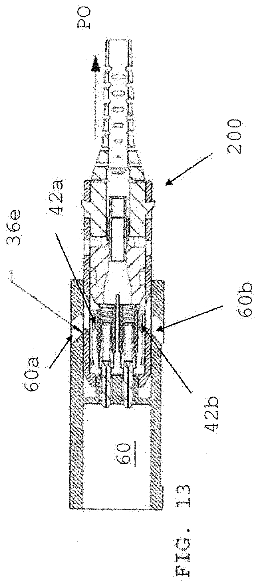
[0052] FIG. 13 is a cross section view of the connector of FIG. 10A being released (PO) using the push/pull boot from a hook-less adapter port, and
[0053] Corresponding reference numbers indicate corresponding parts throughout the drawings.
DETAILED DESCRIPTION
[0054] This disclosure is not limited to the particular systems, devices and methods described, as these may vary. The terminology used in the description is for the purpose of describing the particular versions or embodiments only, and is not intended to limit the scope.
[0055] As used in this document, the singular forms "a," "an," and "the" include plural references unless the context clearly dictates otherwise. Unless defined otherwise, all technical and scientific terms used herein have the same meanings as commonly understood by one of ordinary skill in the art. Nothing in this disclosure is to be construed as an admission that the embodiments described in this disclosure are not entitled to antedate such disclosure by virtue of prior invention. As used in this document, the term "comprising" means "including, but not limited to."
[0056] The following terms shall have, for the purposes of this application, the respective meanings set forth below.
[0057] A connector, as used herein, refers to a device and/or components thereof that connects a first module or cable to a second module or cable. The connector may be configured for fiber optic transmission or electrical signal transmission. The connector may be any suitable type now known or later developed, such as, for example, a ferrule connector (FC), a fiber distributed data interface (FDDI) connector, an LC connector, a mechanical transfer (MT) connector, a square connector (SC) connector, a CS connector, or a straight tip (ST) connector. The connector may generally be defined by a connector housing body. In some embodiments, the housing body may incorporate any or all of the components described herein.
[0058] A "fiber optic cable" or an "optical cable" refers to a cable containing one or more optical fibers for conducting optical signals in beams of light. The optical fibers can be constructed from any suitable transparent material, including glass, fiberglass, and plastic. The cable can include a jacket or sheathing material surrounding the optical fibers. In addition, the cable can be connected to a connector on one end or on both ends of the cable.
[0059] Various embodiments described herein generally provide a remote release mechanism such that a user can remove cable assembly connectors that are closely spaced together on a high density panel without damaging surrounding connectors, accidentally disconnecting surrounding connectors, disrupting transmissions through surrounding connectors, and/or the like. Various embodiments also provide narrow-pitch LC duplex connectors and narrow-width multi-fiber connectors, for use, for example, with future narrow-pitch LC SFPs and future narrow width SFPs. The remote release mechanisms allow use of the narrow-pitch LC duplex connectors and narrow-width multi-fiber connectors in dense arrays of narrow-pitch LC SFPs and narrow-width multi-fiber SFPs.
[0060] FIG. 1A depicts a prior art adapter (10) configured to receive and secured snap-in hooks (12) with a ferrule alignment sleeve, with one snap-in hook per an adapter port. This forms an adapter port with a hook (12) to receive and secure a small-form factor connector as depicted 2B. FIG. 1B is a top view of the adapter (10) of FIG. 1A through cut-outs (10a) that help to secure snap-in hooks within the adapter port. FIG. 1C is a front view of the snap-in hooks (12) within a port defined by spaced apart inner channels within the outer housing wall of the adapter and section line A-A. FIG. 1D.1 is a cross section along line A-A with snap-in hook clip (16) (refer to FIG. 1D.3) secured by an adapter housing internal rib (14), as depicted in FIG. 1D.2 snap-in hook latches. A set of opposing latch hooks (12a, 12b) secure a connector upon insertion of the connector into a port of the adapter. The snap-in hook assembly of FIG. 1D.3 has flexible latch (18) arms to secure the connector.
[0061] FIG. 2A depicts an exploded view of a small form factor connector configured to be secured within the adapter (10) of FIG. Snap-in hook latches are secured within opposing recesses a, b) of the inner front body or housing (refer to FIG. 4A) secured within the sliding outer housing (20). FIG. 2A depicts a strain relief boot (32) with opposing boot hooks (32.1, 32.2) (refer to FIG. 3B) to form a push/pull boot, a crimp ring (30) with heat shrink tubing at a distal end, a back-post and spring (28) pushed configured to accept the crimp ring at a proximal end of the crimp, ring (30), a pair of basis springs (26) to bias forward a corresponding flanged ferrules (24) with at least one optical fiber within, the ferrule, and open sidewall, inner housing (22) that accepts and secured the back-post and spring pusher (28) at a distal end of the inner housing (22) with a pair of opposing protrusions on the back-post secured with a pair of corresponding openings at a distal end of the inner housing (22), and a sliding outer housing (20) that accepts the above mentioned assembly when the push/pull boot is secured to the outer housing at a distal end of the housing. The push/pull boot has a pair of opposing hoot hooks (32.1, 32.2) that are secured within a pair of opposing openings (20.1, 20.2) at the distal of the housing (refer to FIG. 3B), and when the hoot hooks (32.1, 32.2) are secured within the housing openings, the connector assembled as shown in FIG. 2B. FIG. 2B depicts the assembled connector (100) with opposing recesses (38) formed within the inner front body and accessible at a proximal end of the connector, the distal end defined by the push/pull boot with opposing boot hooks (32.1, 32.2). The connector outer housing has opposing alignment keys (35a) that align and guide the connector into an adapter port.
[0062] FIG. 3A depicts outer housing (20) (sometimes called a slider outer housing) and strain relief boot (32) (also called a push/pull boot) that is secured by the opposing boot latches (32.1, 32.2) (refer to FIG. 3B) at a proximal end of the push/pull boot into latch openings (20.1, 20.2) at a distal end of the of slider outer housing (20) (refer to FIG. 38). FIG. 3C is a front view of the small form factor connector along section line B-1B, FIG. 3D is a cross-section view, along section line B-B of FIG. 3C after boot is secured to distal end of slider housing (20) and depicts boot latches (32.1, 32.2) within openings at a distal end of sliding outer housing. The assembly connector of FIG. 3D is a push/pull boot connector similar disclosed in U.S. Pat. Application 2019/0243072A1 to Takano, the subject matter of which is fully disclosed in the present invention.
[0063] FIG. 4A depicts an exploded view of inner housing (22), flanged ferrules (24), ferrule springs (26) and back body and backpost spring pusher (28), which is the back post to receive the crimp ring to secure the fiber optic cable at a first end or distal end, and a spring push to secure ferrules with bias springs within inner body after assembly at a second end or proximal end. FIG. 4B.1 is a front view of the assembled inner assembly along section line C-C. FIG. 4B.2 is a cross section view along line C-C of FIG. 481 FIG. 4C depicts ferrule springs (26a, 26b) compressed under force created by securing backpost spring pusher within inner front body (22) via opposing backpost-spring pusher latches (27a, 27b) within openings at a distal end of inner front body.
[0064] FIG. 5A depicts adapter housing (10) with ports (10a-10d) each having snap-in hook assembly secured therein, and prior to insertion of an assembled small form factor connector (100) within an adapter port. FIG. 5B is an exploded view of the adapter (10) with snap-in hook assembly using the push/pull boot to insert the connector (100) into an adapter port. FIG. 5C is the connector inserted into adapter port where the opposing latch hooks (18) are secured with the opposing inner front body recesses secured within the connector housing, thereby latching the connector within the adapter port. FIG. 5D depicts the connector being released from the adapter port when a user pulls distally or rearward on the push/pull boot or strain relief. When the user pulls the push/pull boot in the direction of arrow A or in the distal/rearward direction, the latch hook (12a) is moved out of recess (38), as depicted in the Takano and FIG. 5D.
[0065] FIG. 6A depicts assembled small form factor connector (200) according to an embodiment of the present invention. As described in the figures below, the connector outer housing has a pair of opposing openings nearer a proximal end of the outer housing configured to allow pair of resilient latches secured with the inner front body to protrude through openings. The resilient latches protrude through a pair of opposing openings formed in a top wall portion and bottom wall portion of the receptacle housing, as depicted at FIG. 11A. FIG. 6B depicts an exploded view of the small form factor connector (200) depicted in FIG. 8A, further comprises an outer housing (36), an inner front body (38.1) with opposing recesses formed on a top portion (23a) and a bottom portion (23b) of the inner front body (refer to FIG. 8A), the latch holes (38a, 38a) are configured to accept, a resilient latch (42) within the recess. The resilient latch (42) is formed from a metal or a plastic which is characterized by being flexible with breaking when bent from an angle less than ninety (90) degrees about zero (0) degrees relative to a normal formed with the longitudinal bore (L-L') (refer to FIG. 6B) of the outer housing. The inner front body (38.1) accepts a pair of opposing LC-type optical ferrules (44) biased by a corresponding spring (46) at a distal end of the flanged LC-type optical ferrules. Backpost-spring pusher (48) applies a pre-determined load to ensure the springs bias the LC-type optical ferrules forward. The backpost-spring pusher (48) has a pair of opposing latch hooks (37a, 37b) (refer to FIG. 8A) that are accepted into a pair of opposing latch holes (38a, 38b) formed at a distal end of the inner front body (refer to refer to FIG. 8A). The backpost-spring pusher (48) forms an inner front body assembly or inner housing assembly. Referring to FIG. 6B a crimp ring (51) with a heat shrink tubing is crimped onto a post formed at a distal end of the backpost-spring pusher (48). A push/pull boot, is secured to a distal end of the connector outer housing. As depicted in FIG. 7B, a pair of opposing boot latches (32.1, 32.2) are received in a corresponding latch holes (36a, 36b) at the distal end of the connector outer housing (36). Once the push/pull boot is secured to the outer housing (36), with the inner front body assembly, the small form factor connector (200) is assembled according to the present invention with the resilient latch protruding from the proximal opening formed in the outer housing, as depicted in FIG. 9D.
[0066] FIG. 7A depicts an exploded view of connector outer housing (36) positioned to accept push/pull boot (32) at a distal end of the outer housing (36). FIG. 7B depicts opposing boot latches (32.1, 32.2) on the push/pull boot prior to being secured to housing via latch holes (36a, 36b), at a distal end of the outer housing (36), configured to accept and secure the boot latches (32.1, 32.2). FIG. 7C is a cross-section of connector assembly (200) along section line A-A. FIG. 7D depicts angled openings (36c, 33d) for the resilient latches (42) secured to the inner front body. Angled opening (36c, 36d) allows for a full travel of the spring latch (42) without binding or jamming within the connector outer housing (36), and further allows for a reduced profile or extension, of the resilient latch (42) beyond the outer housing itself. The angled surface is less than ninety (90) degrees (40a, 40b) to a normal formed with the longitudinal bore of the connector outer housing.
[0067] FIG. 8A depicts an exploded view of inner front body (38.1), flanged ferrules (44) holding a LC-type optical ferrule, ferrule bias springs (46) and backpost-spring pusher (48) with opposing latch hooks (37a, 37b) to secure and compress springs when backpost-spring pusher (48) is secured within the latch holes (38a, 38b) at a distal end of inner front body housing. FIG. 8B is a front view along section line B-B of the inner front body assembled (50). FIG. 8C is a side view of the inner front body assembly with LC-type optical ferrules protruding from within the inner front body, FIG. 81) depicts assembled FIG. 8A. The backpost-spring pusher latch hooks (37a, 37b) secured within latch holes (38a, 38b) at a distal end of inner front body thereby compressing ferrule springs (26a, 26b) and thus ferrules as shown. The backpost-spring pusher compresses the ferrule bias springs to a desired pre-load force necessary to maintain the LC-type optical ferrules in a biased or forward position.
[0068] FIG. 9A depicts an exploded view of small form factor connector further illustrating the assembly of the resilient latches (42a, 42b) with the top and bottom portions of the inner front body having a recess therein (39a, 39b). The connector is assembled in the direction of arrow A, after the resilient latches are installed with inner front body as depicted in FIG. 9B. FIG. 9B is a zoomed view of spring resilient latches (42a, 42b) prior to securing to inner front body. FIG. 9C depicts assembling the small form factor connector in the direction of arrow A1 and arrow A2, after resilient latches secured to inner front body. FIG. 9D depicts the push/pull boot or sometimes called a strain relief for the incoming fiber optic cable is attached and secured to distal end of connector outer housing with resilient latches (42a, 42b) protruding through outer housing.
[0069] FIG. 10A depicts a side view of small form factor connector according to the present invention, with the resilient latches (42a, 42b) protruding through the connector outer housing. FIG. 10B is a top view of the connector of FIG. 10A with resilient latch (42a). FIG. 10C is a cross-section view alone section line C-C of FIG. 10B. FIG. 10C depicts push-pull boot latched to connector outer housing at a distal end, with resilient latches (42a, 42b) protruding through the outer housing at a proximal end. FIG. 10D depicts a view along section line C-C of FIG. 10B, and shows pulling, back the push/pull boot in direction of the arrow while connector outer housing depresses the resilient latches (42a, 42b) into a corresponding recess (39a, 39b) formed in the inner housing or inner front body.
[0070] FIG. 11A depicts inserting the connector (200) of FIG. 10 into port of a receptacle (60). The receptacle port (60) does not contain snap-in hooks. The receptacle port (60) is configured to accept and secure resilient latches, for example, by an opening through a top wall portion (60a.1) and a bottom wall portion (60b.1) of the receptacle outer housing. FIG. 11B depicts inserting connector (200) of FIG. 10 via connector push/pull boot into a receptacle port by pushing on the push/pull boot in a forward or proximal direction PI. FIG. 11C depicts an inner edge (52) of receptacle outer housing depressing resilient latch into recess of inner front body (refer to FIG. 10B) upon insertion into the receptacle port Openings (60a, 60b) at distal end of the housing (60) are sized in width to correspond to the width of openings (38a, 38b) in the inner front body (38.1) to limit the horizontal travel of the push/pull boot and thus the travel of outer housing (60) over the inner front body assembly (50) with backpost-spring pusher (48). The limited travel ensure the resilient latches are within the recess (39a, 39b) without binding the resilient latches in those recesses. Binding the recesses can result in damaging the resilient latch spring constant or force.
[0071] FIG. 12 depicts resilient latch (42a, 42b) entering a port or an opening in receptacle housing or receptacle (60). As the small form factor connector (200) is fully inserted into the receptacle port (PI), resilient latch (42a, 42b) expand into corresponding openings formed in the top wall portion (60a.1) or bottom wall portion (60b. 1) of the receptacle housing. So when the small form factor connector (200) is frilly seated in the receptacle (60), the resilient latches protrude through the opening's in the receptacle walls. The opening in the receptacle wall is angled more than ninety (90) degrees from a normal to the longitudinal bore of the small form factor connector (60a, 60b). The angle at ninety (90) degrees or greater guides the resilient latch through the opening of the receptacle wall without binding or jamming. FIG. 13 depicts releasing the small form factor connector (200) from the receptacle port by pulling (PO) the push/pull boot release in a distal direction. As the small form factor connector is pulled distally, the resilient latch (42a 42b) travels down the angled inner wall of openings (60a, 60b) formed in the receptacle housing (60) configured to receive the resilient latch, as depicted in FIG. 12, and when the outer housing is pulled distally by the push/pull boot, the outer housing wall (36e) traps or secures the resilient latch in the recesses (39a, 39b) formed in the inner front body as shown in FIG. 13, as the outer housing (36) slides over the resilient latch (42a, 42b) thereby pushing the resilient latch through the openings (60a, 60b) and into the recesses (39a, 39b). Still referring to FIG. 13, the size or width of the opening (60a, 60b) at the distal of the connector outer housing (refer to FIG. 11C) or the latch hole width or angled opening (36c, 36d) (FIG. 7B) limits the travel of the connector outer housing so the outer housing depresses the resilient latch within the recess of the front body.
[0072] Various of the above-disclosed and other features and functions, or alternatives thereof, may be combined into man other different systems or applications. Various presently unforeseen or unanticipated alternatives, modifications, variations or improvements therein may be subsequently made by those skilled in the art, each of which is also intended to be encompassed by the disclosed embodiments.
* * * * *
D00000
D00001
D00002
D00003
D00004
D00005
D00006
D00007
D00008
D00009
D00010
D00011
D00012
D00013
D00014
D00015

D00016

D00017
D00018

D00019

D00020

D00021
D00022
D00023

D00024
D00025

D00026
XML
uspto.report is an independent third-party trademark research tool that is not affiliated, endorsed, or sponsored by the United States Patent and Trademark Office (USPTO) or any other governmental organization. The information provided by uspto.report is based on publicly available data at the time of writing and is intended for informational purposes only.
While we strive to provide accurate and up-to-date information, we do not guarantee the accuracy, completeness, reliability, or suitability of the information displayed on this site. The use of this site is at your own risk. Any reliance you place on such information is therefore strictly at your own risk.
All official trademark data, including owner information, should be verified by visiting the official USPTO website at www.uspto.gov. This site is not intended to replace professional legal advice and should not be used as a substitute for consulting with a legal professional who is knowledgeable about trademark law.