Pore Pressure Prediction
Yan; Gong Rui ; et al.
U.S. patent application number 16/303141 was filed with the patent office on 2020-10-22 for pore pressure prediction. The applicant listed for this patent is Schlumberger Technology Corporation. Invention is credited to Chang Liu, Ping Lu, Gong Rui Yan, Jing Zhang, Ping Zhang.
| Application Number | 20200333505 16/303141 |
| Document ID | / |
| Family ID | 1000004971115 |
| Filed Date | 2020-10-22 |


| United States Patent Application | 20200333505 |
| Kind Code | A1 |
| Yan; Gong Rui ; et al. | October 22, 2020 |
Pore Pressure Prediction
Abstract
Methods, computing systems, and computer-readable media for predicting pore pressure. As an example, the method includes receiving data representing a subterranean domain, modeling the domain based on the data, ranking the data, testing and validating the model, calibrating the model, and predicting a pore pressure in the domain.
| Inventors: | Yan; Gong Rui; (Beijing, CN) ; Zhang; Ping; (Beijing, CN) ; Lu; Ping; (Beijing, CN) ; Zhang; Jing; (Beijing, CN) ; Liu; Chang; (Aberdeen, GB) | ||||||||||
| Applicant: |
|
||||||||||
|---|---|---|---|---|---|---|---|---|---|---|---|
| Family ID: | 1000004971115 | ||||||||||
| Appl. No.: | 16/303141 | ||||||||||
| Filed: | June 3, 2016 | ||||||||||
| PCT Filed: | June 3, 2016 | ||||||||||
| PCT NO: | PCT/CN2016/084635 | ||||||||||
| 371 Date: | November 19, 2018 |
| Current U.S. Class: | 1/1 |
| Current CPC Class: | G06F 30/27 20200101; G01V 99/005 20130101; E21B 49/00 20130101; G06F 2113/08 20200101; E21B 2200/20 20200501 |
| International Class: | G01V 99/00 20060101 G01V099/00; E21B 49/00 20060101 E21B049/00; G06F 30/27 20060101 G06F030/27 |
Claims
1. A method for predicting pore pressure, comprising: receiving data representing a subterranean domain; modeling the domain based on the data; ranking the data; testing and validating the model; calibrating the model; and predicting a pore pressure in the domain.
2. The method of claim 1, further comprising cross-checking the model continuously as real-time data is received.
3. A computing system, comprising: one or more processors; and a memory system comprising one or more non-transitory computer-readable media storing instructions that, when executed by at least one of the one or more processors, cause the computing system to perform operations, the operations comprising: receiving data representing a subterranean domain; modeling the domain based on the data; ranking the data; testing and validating the model; calibrating the model; and predicting a pore pressure in the domain.
4. A non-transitory computer-readable medium storing instructions that, when executed by one or more processors of a computing system, cause the computing system to perform operations, the operations comprising: receiving data representing a subterranean domain; modeling the domain based on the data; ranking the data; testing and validating the model; calibrating the model; and predicting a pore pressure in the domain.
Description
BACKGROUND
[0001] Over the past few decades, with more wells drilled, our understandings on formation pore pressure and measured data are accumulated continuously. However, some limitations and the inapplicability of these current physical methods remains. For example, in some basins where formation overpressure is dominated by complex overpressure mechanisms, and this makes the model-based approaches less reliable or inapplicable. Further, prediction results from these models depends on the experiences of people who are doing the jobs, for example, the "site-specific trend line" used in Eaton's model. Additionally, lack of intelligent and integrated "data and model" systems to give a more reliable pore pressure prediction is an issue, as the current approaches rely on individual data (for example sonic or resistivity) and not the whole data and information acquired (Data Lake), especially in real time drilling execution phase where large amounts of data are received continuously (e.g., drilling data, i.e., the D-exponent, LWD data and Mud logging, or MDT pressure testing data).
[0002] Further, an accurate and real time estimation of formation pore pressure facilitates safe and cost-effective drilling. Inaccurate pore pressure prediction can result in increased drilling risks, such as kicks/blowouts, mud losses, stuck pipes, wellbore instability, extra/unnecessary casing points, even loss of the entire well, which may result in extensive damage to equipment and risk the safety of rig personnel.
[0003] Numerous methods have been developed for estimating pore fluid pressure from geophysical data and drilling data. Empirical approaches equate departures from the normal trend line of some porosity-dependent measurement to an equivalent pore pressure gradient. Recent methods have followed the more fundamental effective stress approach.
SUMMARY
[0004] Methods, computing systems, and computer-readable media for predicting pore pressure. As an example, the method includes receiving data representing a subterranean domain, modeling the domain based on the data, ranking the data, testing and validating the model, calibrating the model, and predicting a pore pressure in the domain. In some embodiments, the method may also include cross-checking the model as real-time data is received.
[0005] It will be appreciated that the foregoing summary is intended merely to introduce a subset of the features described below, and therefore is not to be considered exhaustive or otherwise limiting.
BRIEF DESCRIPTION OF THE DRAWINGS
[0006] The accompanying drawings, which are incorporated in and constitute a part of this specification, illustrate embodiments of the present teachings and together with the description, serve to explain the principles of the present teachings. In the figures:
[0007] FIG. 1 illustrates an example of a system that includes various management components to manage various aspects of a geologic environment, according to an embodiment.
[0008] FIG. 2 illustrates a flowchart of a method for pore pressure prediction, according to an embodiment.
[0009] FIG. 3 illustrates a flowchart of a method for pore pressure prediction in real-time drilling execution, according to an embodiment.
[0010] FIG. 4 illustrates a schematic view of a computing system, according to an embodiment.
DETAILED DESCRIPTION
[0011] Reference will now be made in detail to embodiments, examples of which are illustrated in the accompanying drawings and figures. In the following detailed description, numerous specific details are set forth in order to provide a thorough understanding of the invention. However, it will be apparent to one of ordinary skill in the art that the invention may be practiced without these specific details. In other instances, well-known methods, procedures, components, circuits, and networks have not been described in detail so as not to unnecessarily obscure aspects of the embodiments.
[0012] It will also be understood that, although the terms first, second, etc. may be used herein to describe various elements, these elements should not be limited by these terms. These terms are only used to distinguish one element from another. For example, a first object or step could be termed a second object or step, and, similarly, a second object or step could be termed a first object or step, without departing from the scope of the present disclosure. The first object or step, and the second object or step, are both, objects or steps, respectively, but they are not to be considered the same object or step.
[0013] The terminology used in the description herein is for the purpose of describing particular embodiments and is not intended to be limiting. As used in this description and the appended claims, the singular forms "a," "an" and "the" are intended to include the plural forms as well, unless the context clearly indicates otherwise. It will also be understood that the term "and/or" as used herein refers to and encompasses any possible combinations of one or more of the associated listed items. It will be further understood that the terms "includes," "including," "comprises" and/or "comprising," when used in this specification, specify the presence of stated features, integers, steps, operations, elements, and/or components, but do not preclude the presence or addition of one or more other features, integers, steps, operations, elements, components, and/or groups thereof. Further, as used herein, the term "if" may be construed to mean "when" or "upon" or "in response to determining" or "in response to detecting," depending on the context.
[0014] Attention is now directed to processing procedures, methods, techniques, and workflows that are in accordance with some embodiments. Some operations in the processing procedures, methods, techniques, and workflows disclosed herein may be combined and/or the order of some operations may be changed.
[0015] FIG. 1 illustrates an example of a system 100 that includes various management components 110 to manage various aspects of a geologic environment 150 (e.g., an environment that includes a sedimentary basin, a reservoir 151, one or more faults 153-1, one or more geobodies 153-2, etc.). For example, the management components 110 may allow for direct or indirect management of sensing, drilling, injecting, extracting, etc., with respect to the geologic environment 150. In turn, further information about the geologic environment 150 may become available as feedback 160 (e.g., optionally as input to one or more of the management components 110).
[0016] In the example of FIG. 1, the management components 110 include a seismic data component 112, an additional information component 114 (e.g., well/logging data), a processing component 116, a simulation component 120, an attribute component 130, an analysis/visualization component 142 and a workflow component 144. In operation, seismic data and other information provided per the components 112 and 114 may be input to the simulation component 120.
[0017] In an example embodiment, the simulation component 120 may rely on entities 122. Entities 122 may include earth entities or geological objects such as wells, surfaces, bodies, reservoirs, etc. In the system 100, the entities 122 can include virtual representations of actual physical entities that are reconstructed for purposes of simulation. The entities 122 may include entities based on data acquired via sensing, observation, etc. (e.g., the seismic data 112 and other information 114). An entity may be characterized by one or more properties (e.g., a geometrical pillar grid entity of an earth model may be characterized by a porosity property). Such properties may represent one or more measurements (e.g., acquired data), calculations, etc.
[0018] In an example embodiment, the simulation component 120 may operate in conjunction with a software framework such as an object-based framework. In such a framework, entities may include entities based on pre-defined classes to facilitate modeling and simulation. A commercially available example of an object-based framework is the MICROSOFT.RTM. .NET.RTM. framework (Redmond, Wash.), which provides a set of extensible object classes. In the .NET.RTM. framework, an object class encapsulates a module of reusable code and associated data structures. Object classes can be used to instantiate object instances for use in by a program, script, etc. For example, borehole classes may define objects for representing boreholes based on well data.
[0019] In the example of FIG. 1, the simulation component 120 may process information to conform to one or more attributes specified by the attribute component 130, which may include a library of attributes. Such processing may occur prior to input to the simulation component 120 (e.g., consider the processing component 116). As an example, the simulation component 120 may perform operations on input information based on one or more attributes specified by the attribute component 130. In an example embodiment, the simulation component 120 may construct one or more models of the geologic environment 150, which may be relied on to simulate behavior of the geologic environment 150 (e.g., responsive to one or more acts, whether natural or artificial). In the example of FIG. 1, the analysis/visualization component 142 may allow for interaction with a model or model-based results (e.g., simulation results, etc.). As an example, output from the simulation component 120 may be input to one or more other workflows, as indicated by a workflow component 144.
[0020] As an example, the simulation component 120 may include one or more features of a simulator such as the ECLIPSE.TM. reservoir simulator (Schlumberger Limited, Houston Tex.), the INTERSECT reservoir simulator (Schlumberger Limited, Houston Tex.), etc. As an example, a simulation component, a simulator, etc. may include features to implement one or more meshless techniques (e.g., to solve one or more equations, etc.). As an example, a reservoir or reservoirs may be simulated with respect to one or more enhanced recovery techniques (e.g., consider a thermal process such as SAGD, etc.).
[0021] In an example embodiment, the management components 110 may include features of a commercially available framework such as the PETREL.RTM. seismic to simulation software framework (Schlumberger Limited, Houston, Tex.). The PETREL.RTM. framework provides components that allow for optimization of exploration and development operations. The PETREL.RTM. framework includes seismic to simulation software components that can output information for use in increasing reservoir performance, for example, by improving asset team productivity. Through use of such a framework, various professionals (e.g., geophysicists, geologists, and reservoir engineers) can develop collaborative workflows and integrate operations to streamline processes. Such a framework may be considered an application and may be considered a data-driven application (e.g., where data is input for purposes of modeling, simulating, etc.).
[0022] In an example embodiment, various aspects of the management components 110 may include add-ons or plug-ins that operate according to specifications of a framework environment. For example, a commercially available framework environment marketed as the OCEAN.RTM. framework environment (Schlumberger Limited, Houston, Tex.) allows for integration of add-ons (or plug-ins) into a PETREL.RTM. framework workflow. The OCEAN.RTM. framework environment leverages .NET.RTM. tools (Microsoft Corporation, Redmond, Wash.) and offers stable, user-friendly interfaces for efficient development. In an example embodiment, various components may be implemented as add-ons (or plug-ins) that conform to and operate according to specifications of a framework environment (e.g., according to application programming interface (API) specifications, etc.).
[0023] FIG. 1 also shows an example of a framework 170 that includes a model simulation layer 180 along with a framework services layer 190, a framework core layer 195 and a modules layer 175. The framework 170 may include the commercially available OCEAN.RTM. framework where the model simulation layer 180 is the commercially available PETREL.RTM. model-centric software package that hosts OCEAN.RTM. framework applications. In an example embodiment, the PETREL.RTM. software may be considered a data-driven application. The PETREL.RTM. software can include a framework for model building and visualization.
[0024] As an example, a framework may include features for implementing one or more mesh generation techniques. For example, a framework may include an input component for receipt of information from interpretation of seismic data, one or more attributes based at least in part on seismic data, log data, image data, etc. Such a framework may include a mesh generation component that processes input information, optionally in conjunction with other information, to generate a mesh.
[0025] In the example of FIG. 1, the model simulation layer 180 may provide domain objects 182, act as a data source 184, provide for rendering 186 and provide for various user interfaces 188. Rendering 186 may provide a graphical environment in which applications can display their data while the user interfaces 188 may provide a common look and feel for application user interface components.
[0026] As an example, the domain objects 182 can include entity objects, property objects and optionally other objects. Entity objects may be used to geometrically represent wells, surfaces, bodies, reservoirs, etc., while property objects may be used to provide property values as well as data versions and display parameters. For example, an entity object may represent a well where a property object provides log information as well as version information and display information (e.g., to display the well as part of a model).
[0027] In the example of FIG. 1, data may be stored in one or more data sources (or data stores, generally physical data storage devices), which may be at the same or different physical sites and accessible via one or more networks. The model simulation layer 180 may be configured to model projects. As such, a particular project may be stored where stored project information may include inputs, models, results and cases. Thus, upon completion of a modeling session, a user may store a project. At a later time, the project can be accessed and restored using the model simulation layer 180, which can recreate instances of the relevant domain objects.
[0028] In the example of FIG. 1, the geologic environment 150 may include layers (e.g., stratification) that include a reservoir 151 and one or more other features such as the fault 153-1, the geobody 153-2, etc. As an example, the geologic environment 150 may be outfitted with any of a variety of sensors, detectors, actuators, etc. For example, equipment 152 may include communication circuitry to receive and to transmit information with respect to one or more networks 155. Such information may include information associated with downhole equipment 154, which may be equipment to acquire information, to assist with resource recovery, etc.
[0029] Other equipment 156 may be located remote from a well site and include sensing, detecting, emitting or other circuitry. Such equipment may include storage and communication circuitry to store and to communicate data, instructions, etc. As an example, one or more satellites may be provided for purposes of communications, data acquisition, etc. For example, FIG. 1 shows a satellite in communication with the network 155 that may be configured for communications, noting that the satellite may additionally or instead include circuitry for imagery (e.g., spatial, spectral, temporal, radiometric, etc.).
[0030] FIG. 1 also shows the geologic environment 150 as optionally including equipment 157 and 158 associated with a well that includes a substantially horizontal portion that may intersect with one or more fractures 159. For example, consider a well in a shale formation that may include natural fractures, artificial fractures (e.g., hydraulic fractures) or a combination of natural and artificial fractures. As an example, a well may be drilled for a reservoir that is laterally extensive. In such an example, lateral variations in properties, stresses, etc. may exist where an assessment of such variations may assist with planning, operations, etc. to develop a laterally extensive reservoir (e.g., via fracturing, injecting, extracting, etc.). As an example, the equipment 157 and/or 158 may include components, a system, systems, etc. for fracturing, seismic sensing, analysis of seismic data, assessment of one or more fractures, etc.
[0031] As mentioned, the system 100 may be used to perform one or more workflows. A workflow may be a process that includes a number of worksteps. A workstep may operate on data, for example, to create new data, to update existing data, etc. As an example, a may operate on one or more inputs and create one or more results, for example, based on one or more algorithms. As an example, a system may include a workflow editor for creation, editing, executing, etc. of a workflow. In such an example, the workflow editor may provide for selection of one or more pre-defined worksteps, one or more customized worksteps, etc. As an example, a workflow may be a workflow implementable in the PETREL.RTM. software, for example, that operates on seismic data, seismic attribute(s), etc. As an example, a workflow may be a process implementable in the OCEAN.RTM. framework. As an example, a workflow may include one or more worksteps that access a module such as a plug-in (e.g., external executable code, etc.).
[0032] Embodiments of the present disclosure use an Artificial Intelligence (AI) approach to solve the problem. AI technology may be employed to capitalize on its high performance, deep learning capability and data-based multi-variate problem prediction, which may be well-suited for pore pressure predication in accordance with the present implementations.
[0033] In particular, embodiments of the present disclosure may develop an AI-based pore pressure prediction system for drilling and geoscience modeling. This system is built on the basis of Machine Learning and knowledge of subsurface formation pore pressure, training and supporting by ranked data collected from various sources. The system is designed to work both in well planning phase and in real time well drilling execution phase, to provide more accurate and in time pore pressure prediction for a safe and cost effective drilling.
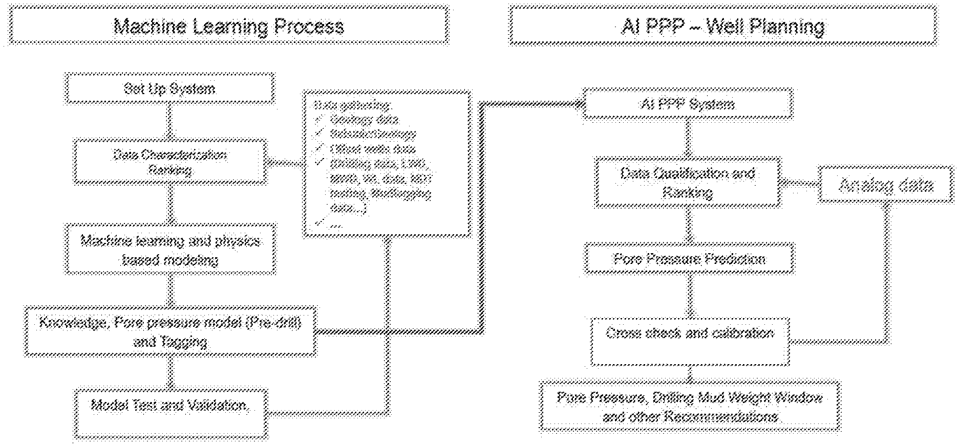
[0034] Example workflow of this system for well planning and for real time drilling are shown in FIGS. 2 and 3, respectively.
[0035] For example, in FIG. 2, the method may begin with a machine learning process. The process may include setting up the system, as well as data characterization and ranking. The data characterization and ranking may be based on input received through one or more data gathering processes, which may or may not be part of the method. The method may then include machine learning and physics-based modeling, knowledge, pore pressure model (pre-drill) and tagging. The method may then include model test and validation.
[0036] Once the machine learning process is complete, the method may move to artificial intelligence pore pressure prediction (PPP) as part of well planning. The PPP system may qualify and rank data, predict pore pressure, cross-check and calibrate, and then make pore pressure, drilling mud weight windows, and/or other predictions. Further, during cross-checking and calibration the well planning process may refer to analog data, e.g., as collected from or in the wellbore.
[0037] The method of FIG. 3 may be generally similar, except that the AI PPP process may continuously loop back from cross-checking and calibration so as to continuously learn and update/improve the model.
[0038] In some embodiments, the methods of the present disclosure may be executed by a computing system. FIG. 4 illustrates an example of such a computing system 400, in accordance with some embodiments. The computing system 400 may include a computer or computer system 401A, which may be an individual computer system 401A or an arrangement of distributed computer systems. The computer system 401A includes one or more analysis modules 402 that are configured to perform various tasks according to some embodiments, such as one or more methods disclosed herein. To perform these various tasks, the analysis module 402 executes independently, or in coordination with, one or more processors 404, which is (or are) connected to one or more storage media 406. The processor(s) 404 is (or are) also connected to a network interface 407 to allow the computer system 401A to communicate over a data network 409 with one or more additional computer systems and/or computing systems, such as 401B, 401C, and/or 401D (note that computer systems 401B, 401C and/or 401D may or may not share the same architecture as computer system 401A, and may be located in different physical locations, e.g., computer systems 401A and 401B may be located in a processing facility, while in communication with one or more computer systems such as 401C and/or 401D that are located in one or more data centers, and/or located in varying countries on different continents).
[0039] A processor may include a microprocessor, microcontroller, processor module or subsystem, programmable integrated circuit, programmable gate array, or another control or computing device.
[0040] The storage media 406 may be implemented as one or more computer-readable or machine-readable storage media. Note that while in the example embodiment of FIG. 4 storage media 406 is depicted as within computer system 401A, in some embodiments, storage media 406 may be distributed within and/or across multiple internal and/or external enclosures of computing system 401A and/or additional computing systems. Storage media 406 may include one or more different forms of memory including semiconductor memory devices such as dynamic or static random access memories (DRAMs or SRAMs), erasable and programmable read-only memories (EPROMs), electrically erasable and programmable read-only memories (EEPROMs) and flash memories, magnetic disks such as fixed, floppy and removable disks, other magnetic media including tape, optical media such as compact disks (CDs) or digital video disks (DVDs), BLU-RAY.RTM. disks, or other types of optical storage, or other types of storage devices. Note that the instructions discussed above may be provided on one computer-readable or machine-readable storage medium, or may be provided on multiple computer-readable or machine-readable storage media distributed in a large system having possibly plural nodes. Such computer-readable or machine-readable storage medium or media is (are) considered to be part of an article (or article of manufacture). An article or article of manufacture may refer to any manufactured single component or multiple components. The storage medium or media may be located either in the machine running the machine-readable instructions, or located at a remote site from which machine-readable instructions may be downloaded over a network for execution.
[0041] In some embodiments, computing system 400 contains one or more PPP module(s) 408. In the example of computing system 400, the computer system 401A includes the PPPmodule 408. In some embodiments, a single PPPmodule may be used to perform some aspects of one or more embodiments of the methods disclosed herein. In other embodiments, a plurality of PPP 408 modules may be used to perform some aspects of methods herein.
[0042] It should be appreciated that computing system 400 is merely one example of a computing system, and that computing system 400 may have more or fewer components than shown, may combine additional components not depicted in the example embodiment of FIG. 4, and/or computing system 400 may have a different configuration or arrangement of the components depicted in FIG. 4. The various components shown in FIG. 4 may be implemented in hardware, software, or a combination of both hardware and software, including one or more signal processing and/or application specific integrated circuits.
[0043] Further, the steps in the processing methods described herein may be implemented by running one or more functional modules in information processing apparatus such as general purpose processors or application specific chips, such as ASICs, FPGAs, PLDs, or other appropriate devices. These modules, combinations of these modules, and/or their combination with general hardware are included within the scope of the present disclosure.
[0044] Geologic interpretations, models, and/or other interpretation aids may be refined in an iterative fashion; this concept is applicable to the methods discussed herein. This may include use of feedback loops executed on an algorithmic basis, such as at a computing device (e.g., computing system 400, FIG. 4), and/or through manual control by a user who may make determinations regarding whether a given step, action, template, model, or set of curves has become sufficiently accurate for the evaluation of the subsurface three-dimensional geologic formation under consideration.
[0045] The foregoing description, for purpose of explanation, has been described with reference to specific embodiments. However, the illustrative discussions above are not intended to be exhaustive or limiting to the precise forms disclosed. Many modifications and variations are possible in view of the above teachings. Moreover, the order in which the elements of the methods described herein are illustrate and described may be re-arranged, and/or two or more elements may occur simultaneously. The embodiments were chosen and described in order to best explain the principals of the disclosure and its practical applications, to thereby enable others skilled in the art to best utilize the disclosed embodiments and various embodiments with various modifications as are suited to the particular use contemplated.
* * * * *
D00000
D00001
D00002
D00003
D00004
XML
uspto.report is an independent third-party trademark research tool that is not affiliated, endorsed, or sponsored by the United States Patent and Trademark Office (USPTO) or any other governmental organization. The information provided by uspto.report is based on publicly available data at the time of writing and is intended for informational purposes only.
While we strive to provide accurate and up-to-date information, we do not guarantee the accuracy, completeness, reliability, or suitability of the information displayed on this site. The use of this site is at your own risk. Any reliance you place on such information is therefore strictly at your own risk.
All official trademark data, including owner information, should be verified by visiting the official USPTO website at www.uspto.gov. This site is not intended to replace professional legal advice and should not be used as a substitute for consulting with a legal professional who is knowledgeable about trademark law.