Perturbing Air Cooled Condenser Fin
THOME; Ted L. ; et al.
U.S. patent application number 16/850673 was filed with the patent office on 2020-10-22 for perturbing air cooled condenser fin. The applicant listed for this patent is The Babcock & Wilcox Company. Invention is credited to Tony F. HABIB, Billy G. SPRINGER, JR., Ted L. THOME.
| Application Number | 20200333077 16/850673 |
| Document ID | / |
| Family ID | 1000004796048 |
| Filed Date | 2020-10-22 |


View All Diagrams
| United States Patent Application | 20200333077 |
| Kind Code | A1 |
| THOME; Ted L. ; et al. | October 22, 2020 |
PERTURBING AIR COOLED CONDENSER FIN
Abstract
An air cooled condenser fin comprises flow channel walls defining an air flow channel. The flow channel walls include planar sections separated by intermittent flow interruptions which are spaced apart along the air flow channel. The intermittent flow interruptions are defined by the flow channel walls. The intermittent flow interruptions may for example comprise splits formed by a staggered arrangement in which the planar sections of the flow channel walls before and after each split are staggered; or intermittent sinusoidal waves formed into the flow channel walls; or louvers formed into the flow channel walls to create openings passing through the flow channel walls at the louvers. The intermittent flow interruptions may be spaced apart along the air flow channel by at least 5 hydraulic diameters, and in some embodiments by 5-10 hydraulic diameters. A plurality of such air cooled condenser fins are suitably employed with the air flow channels arranged in parallel.
| Inventors: | THOME; Ted L.; (Cuyahoga Falls, OH) ; HABIB; Tony F.; (Lancaster, OH) ; SPRINGER, JR.; Billy G.; (Canal Winchester, OH) | ||||||||||
| Applicant: |
|
||||||||||
|---|---|---|---|---|---|---|---|---|---|---|---|
| Family ID: | 1000004796048 | ||||||||||
| Appl. No.: | 16/850673 | ||||||||||
| Filed: | April 16, 2020 |
Related U.S. Patent Documents
| Application Number | Filing Date | Patent Number | ||
|---|---|---|---|---|
| 62835706 | Apr 18, 2019 | |||
| Current U.S. Class: | 1/1 |
| Current CPC Class: | F28B 1/06 20130101; F28F 3/025 20130101 |
| International Class: | F28B 1/06 20060101 F28B001/06; F28F 3/02 20060101 F28F003/02 |
Claims
1. An air cooled condenser fin comprising: flow channel walls defining an air flow channel; wherein the flow channel walls include planar sections separated by intermittent flow interruptions which are spaced apart along the air flow channel; wherein the intermittent flow interruptions are defined by the flow channel walls.
2. The air cooled condenser fin of claim 1 wherein the intermittent flow interruptions comprise splits formed by a staggered arrangement in which the planar sections of the flow channel walls before and after each split are staggered.
3. The air cooled condenser fin of claim 2 wherein the staggering of the flow channel walls after each split is about one-half of a width of the air flow channel.
4. The air cooled condenser fin of claim 2 wherein the splits are spaced between 5 hydraulic diameters and 10 hydraulic diameters apart along the air flow channel.
5. The air cooled condenser fin of claim 2 wherein the splits are spaced apart along the air flow channel by at least 5 hydraulic diameters.
6. The air cooled condenser fin of claim 1 wherein the intermittent flow interruptions comprise intermittent sinusoidal waves formed into the flow channel walls.
7. The air cooled condenser fin of claim 6 wherein the intermittent sinusoidal waves are spaced between 5 hydraulic diameters and 10 hydraulic diameters apart along the air flow channel.
8. The air cooled condenser fin of claim 6 wherein the intermittent sinusoidal waves are spaced apart along the air flow channel by at least 5 hydraulic diameters.
9. The air cooled condenser fin of claim 1 wherein the intermittent flow interruptions comprise louvers formed into the flow channel walls to create openings passing through the flow channel walls at the louvers.
10. The air cooled condenser fin of claim 9 wherein the louvers are angled between 1 degree and 30 degrees to an air flow direction of the air flow channel.
11. The air cooled condenser fin of claim 9 wherein the flow channel walls are secured to a tube of an air cooled condenser.
12. The air cooled condenser fin of claim 9 wherein the louvers are spaced between 5 hydraulic diameters and 10 hydraulic diameters apart along the air flow channel.
13. The air cooled condenser fin of claim 9 wherein the louvers are spaced apart along the air flow channel by at least 5 hydraulic diameters.
14. The air cooled condenser fin of claim 1 wherein the intermittent flow interruptions are spaced between 5 hydraulic diameters and 10 hydraulic diameters apart along the air flow channel.
15. The air cooled condenser fin of claim 1 wherein the intermittent flow interruptions are spaced apart along the air flow channel by at least 5 hydraulic diameters.
16. An air cooled condenser comprising a plurality of air cooled condenser fins as set forth in claim 1 wherein the air flow channels of the air cooled condenser fins are arranged in parallel.
17. An air cooled condenser comprising: steam/condensate tubes; fins attached to the steam/condensate tubes; wherein the fins comprise flow channel walls defining parallel air flow channels, the flow channel walls including planar sections separated by intermittent flow interruptions which are spaced apart along the air flow channels; wherein the intermittent flow interruptions are defined by the flow channel walls.
18. The air cooled condenser of claim 17 wherein the intermittent flow interruptions comprise splits formed by a staggered arrangement in which the planar sections of the flow channel walls before and after each split are staggered.
19. The air cooled condenser of claim 18 wherein the staggering of the flow channel walls after each split is about one-half of a width of the air flow channel.
20. The air cooled condenser of claim 17 wherein the intermittent flow interruptions comprise intermittent sinusoidal waves formed into the flow channel walls.
21. The air cooled condenser of claim 17 wherein the intermittent flow interruptions comprise louvers formed into the flow channel walls to create openings passing through the flow channel walls at the louvers.
22. The air cooled condenser of claim 21 wherein the louvers are angled between 1 degree and 30 degrees to an air flow direction of the air flow channel.
23. The air cooled condenser of claim 17 wherein the intermittent flow interruptions are spaced between 5 hydraulic diameters and 10 hydraulic diameters apart along the air flow channel.
24. The air cooled condenser of claim 23 wherein the air flow channels are rectangular with the hydraulic diameter D.sub.H,fin of each air flow channel being: D H , fin = 2 ( S f i n .times. H f i n ) S f i n + H f i n ##EQU00005## where H.sub.fin is a fin height and S.sub.fin is a separation between the fin walls defining each air flow channel.
25. The air cooled condenser of claim 23 wherein the hydraulic diameter D.sub.H,fin of each air flow channel is: D H , fin = 4 A P ##EQU00006## where A is the cross-sectional area of each air flow channel and P is the perimeter of the cross-section of each air flow channel.
26. The air cooled condenser of claim 17 wherein the intermittent flow interruptions are spaced apart along the air flow channel by at least 5 hydraulic diameters.
27. The air cooled condenser of claim 26 wherein the air flow channels are rectangular with the hydraulic diameter D.sub.H,fin of each air flow channel being: D H , fin = 2 ( S f i n .times. H f i n ) S f i n + H f i n ##EQU00007## where H.sub.fin is a fin height and S.sub.fin is a separation between the fin walls defining each air flow channel.
28. The air cooled condenser of claim 26 wherein the hydraulic diameter D.sub.H,fin of each air flow channel is: D H , fin = 4 A P ##EQU00008## where A is the cross-sectional area of each air flow channel and P is the perimeter of the cross-section of each air flow channel.
29. The air cooled condenser of claim 17 further comprising: distribution headers connected to feed steam into the steam/condensate tubes; and an air moving system comprising a fan arranged to drive an airflow across the fins attached to the steam/condensate tubes.
30. The air cooled condenser of claim 29 further comprising: risers connected to feed the steam into the distribution headers; wherein the steam/condensate tubes, the distribution headers, the risers, and the air moving system are arranged to form the air cooled condenser as an A-frame type air cooled condenser.
31. The air cooled condenser of claim 17 wherein at least 70% of the intermittent flow interruptions are positioned within a first one-half of a length of the fins closest to an air flow entrance of fins.
32. A method of cooling using an air cooled condenser fin, the method comprising: flowing air through an air flow channel defined by flow channel walls; and interrupting the flowing of air at intermittent flow interruptions defined by the flow channel walls which are spaced apart along the air flow channel.
33. The method of claim 32 wherein the intermittent flow interruptions are placed at locations where a boundary layer of the flowing air has normalized.
34. The method of claim 32 wherein the intermittent flow interruptions are spaced apart along the air flow channel by at least 5 hydraulic diameters.
Description
[0001] This application claims the benefit of U.S. Provisional Application No. 62/835,706 filed Apr. 18, 2019. U.S. Provisional Application No. 62/835,706 filed Apr. 18, 2019 is incorporated herein by reference in its entirety.
BACKGROUND
[0002] The following relates to air cooled condensers, heat exchanger fins and arrays thereof for air cooled condensers, and so forth.
[0003] Traditional heat exchange fins are of the straight or plain variety. Heat transfer occurs through a fin channel wherein air enters in the channel and establishes a fluid boundary layer. Heat transfer normalizes once the fluid boundary layer is established. Some straight fins may have blemishes or other features on their surface as a result of manufacturing processes. As such traditional fin designs may not be entirely straight nor uniform from fin to fin within a fin array.
[0004] A known modification of the straight fin design is to include perforations in the fins to disturb air flow with the flow channel, i.e. pressed or cut perforations. They offer cross channel flow paths and are commonly used in automotive applications. The perforations, while effective at disturbing the fluid boundary layer increasing heat transfer, can be impractical in certain applications as they increase the pressure drop of the air flow.
[0005] Another known fin design employs offset fins. In this design the straight path is cyclically offset within a channel to disturb the boundary layer. This design, as with the perforations, increase heat transfer capability but in doing so also increases pressure drop.
[0006] Another known fin design employs wavy or ruffled fins. In this design the straight fins are curved to form sinusoidal waves. The periodic waves enables disruption of the fluid boundary layer. Haushalter, U.S. Pat. No. 5,209,289 issued May 11, 1993, discloses a modified fin array incorporating wavy offsets in a unique combination.
[0007] Bugler et al., U.S. Publication No. 2018/0023901 A1 published Jan. 25, 2018, discloses a heat exchange tube fin design in which a plurality of arrowhead shapes are pressed into or embossed onto each fin. The pressed arrowhead shapes are grouped into nested pairs, and one of the arrowheads in a pair is pressed as a positive relative to the fin plane and the other of the pair is pressed as a negative relative to the fin plane. The arrowhead pairs are placed in rows parallel to the air flow direction and arrowhead pairs in one row are preferably staggered relative to the arrowhead pairs in the adjacent row along the fin in the air flow direction.
BRIEF SUMMARY
[0008] In some aspects disclosed herein, an air cooled condenser fin comprises flow channel walls defining an air flow channel. The flow channel walls include planar sections separated by intermittent flow interruptions which are spaced apart along the air flow channel. The intermittent flow interruptions are defined by the flow channel walls.
[0009] In some illustrative embodiments, the intermittent flow interruptions comprise splits formed by a staggered arrangement in which the planar sections of the flow channel walls before and after each split are staggered. In some embodiments, the staggering of the flow channel walls after each split is about one-half of a width of the air flow channel.
[0010] In some illustrative embodiments, the intermittent flow interruptions comprise intermittent sinusoidal waves formed into the flow channel walls.
[0011] In some illustrative embodiments, the intermittent flow interruptions comprise louvers formed into the flow channel walls to create openings passing through the flow channel walls at the louvers. In some embodiments, the louvers are angled between 1 degree and 30 degrees to an air flow direction of the air flow channel. In some embodiments, the flow channel walls are secured to a tube of an air cooled condenser.
[0012] In any of the foregoing embodiments, the intermittent flow interruptions are in some more specific embodiments spaced between 5 hydraulic diameters and 10 hydraulic diameters apart along the air flow channel.
[0013] In any of the foregoing embodiments, the intermittent flow interruptions are in some more specific embodiments spaced apart along the air flow channel by at least 5 hydraulic diameters.
[0014] In some aspects disclosed herein, a plurality of air cooled condenser fins as set forth in any of the preceding paragraphs is provided, in which the air flow channels of the air cooled condenser fins are arranged in parallel.
[0015] In some aspects disclosed herein, an air cooled condenser comprises steam/condensate tubes and fins attached to the steam/condensate tubes. The fins comprise flow channel walls defining parallel air flow channels. The flow channel walls include planar sections separated by intermittent flow interruptions which are spaced apart along the air flow channels. The intermittent flow interruptions are defined by the flow channel walls. The intermittent flow interruptions in some embodiments comprise splits formed by a staggered arrangement in which the planar sections of the flow channel walls before and after each split are staggered. The staggering of the flow channel walls after each split is, in some more specific embodiments, about one-half of a width of the air flow channel. The intermittent flow interruptions in some embodiments comprise intermittent sinusoidal waves formed into the flow channel walls. The intermittent flow interruptions in some embodiments comprise louvers formed into the flow channel walls to create openings passing through the flow channel walls at the louvers. The louvers are, in some more specific embodiments, angled between 1 degree and 30 degrees to an air flow direction of the air flow channel. In any of the foregoing embodiments of this paragraph, the intermittent flow interruptions may in some more specific embodiments be spaced between 5 hydraulic diameters and 10 hydraulic diameters apart along the air flow channel. In any of the foregoing embodiments of this paragraph, the intermittent flow interruptions may in some more specific embodiments be spaced apart along the air flow channel by at least 5 hydraulic diameters.
[0016] Some embodiments of an air cooled condenser as set forth in the immediately preceding paragraph further comprise distribution headers connected to feed steam into the steam/condensate tubes, and an air moving system comprising a fan arranged to drive an airflow across the fins attached to the steam/condensate tubes. Some more specific embodiments further include risers connected to feed the steam into the distribution headers, wherein the steam/condensate tubes, the distribution headers, the risers, and the air moving system are arranged to form the air cooled condenser as an A-frame type air cooled condenser or other types.
[0017] In some aspects disclosed herein, a method of cooling using an air cooled condenser fin is disclosed. The method comprises flowing air through an air flow channel defined by flow channel walls, and interrupting the flowing of air at intermittent flow interruptions defined by the flow channel walls which are spaced apart along the air flow channel. In some more specific embodiments, the intermittent flow interruptions are placed at locations where a boundary layer of the flowing air has normalized. In some more specific embodiments, the intermittent flow interruptions are spaced apart along the air flow channel by at least 5 hydraulic diameters.
[0018] These and other non-limiting aspects and/or objects of the disclosure are more particularly described below.
BRIEF DESCRIPTION OF THE DRAWINGS
[0019] The invention may take form in various components and arrangements of components, and in various process operations and arrangements of process operations. The drawings are only for purposes of illustrating preferred embodiments and are not to be construed as limiting the invention. This disclosure includes the following drawings.
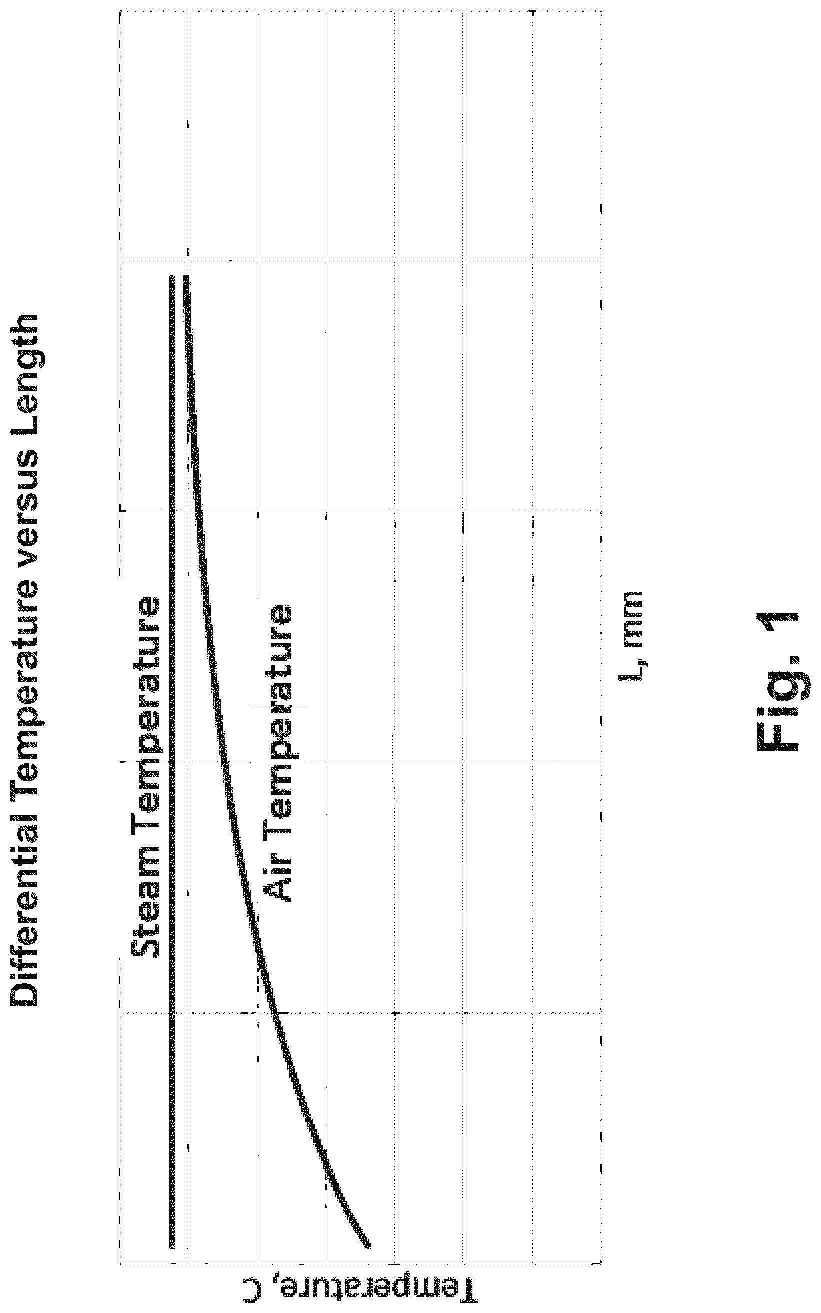
[0020] FIG. 1 diagrammatically shows differential temperature versus length for a planar fin.
[0021] FIG. 2 diagrammatically shows heat transfer coefficient versus length for a planar fin.
[0022] FIG. 3 diagrammatically shows incremental air pressure drop versus length for a planar fin.
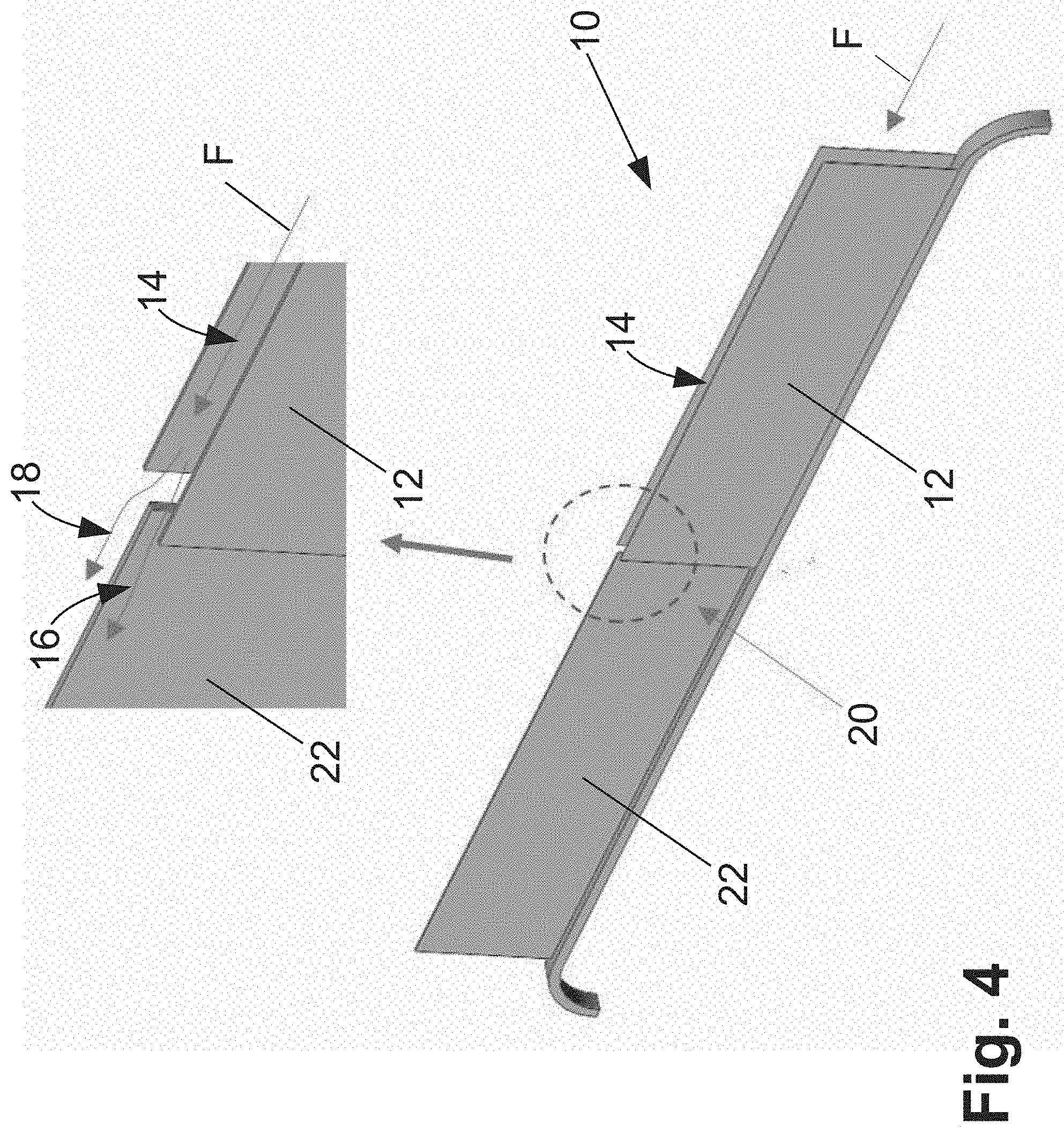
[0023] FIG. 4 diagrammatically shows a perspective view of a portion of an air cooled condenser fin having a single split-fin.
[0024] FIG. 5 diagrammatically shows a top view of a portion of an air cooled condenser fin array including a plurality of splits of the type shown in FIG. 4.
[0025] FIG. 6 diagrammatically shows a perspective view air flow velocity map for the split fin air flow.
[0026] FIG. 7 diagrammatically shows a perspective view of a portion of an air cooled condenser fin having intermittent sinusoidal waves.
[0027] FIG. 8 diagrammatically shows a perspective view of a portion of an air cooled condenser fin having louvers.
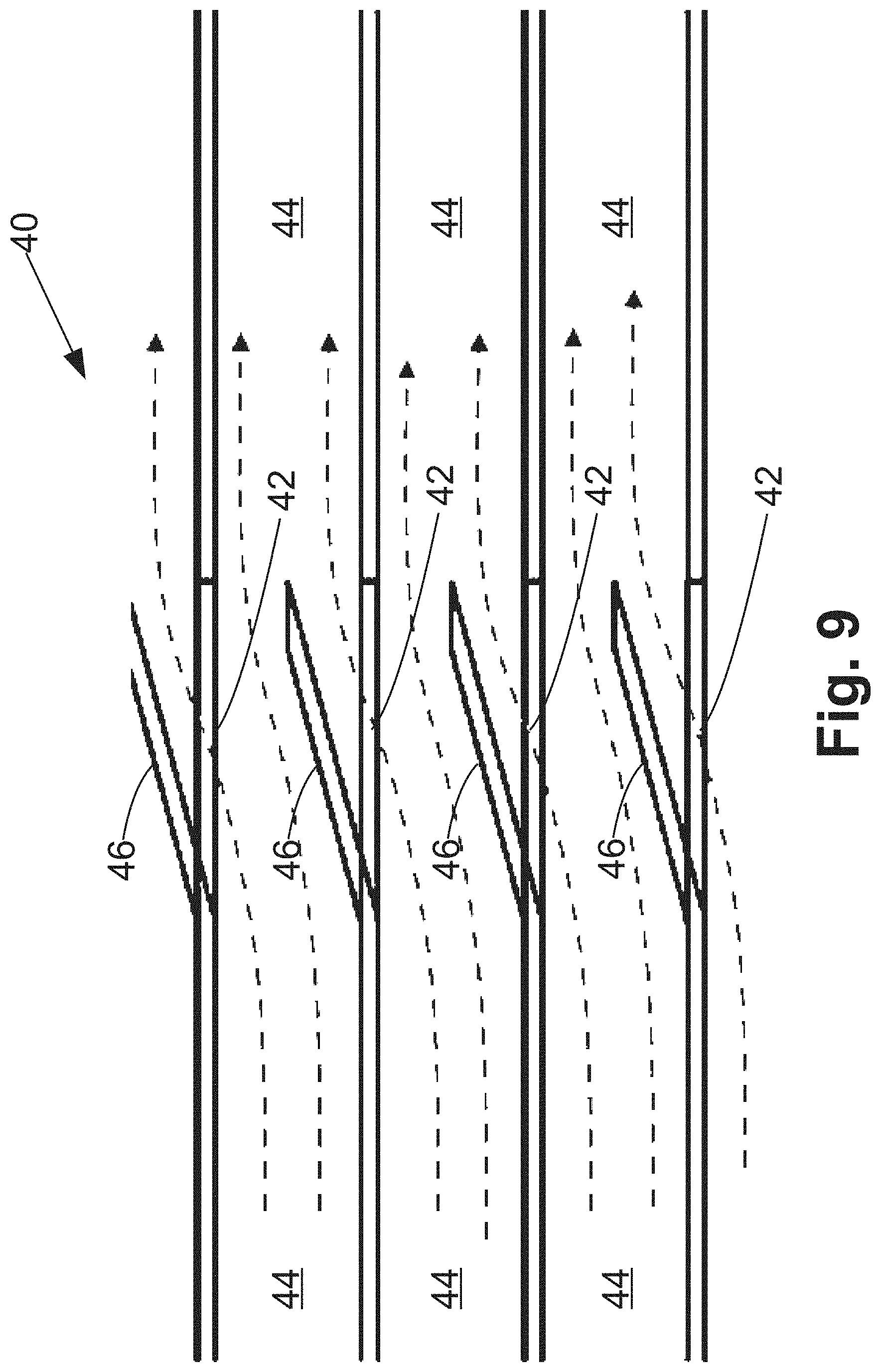
[0028] FIG. 9 diagrammatically shows a top view of a portion of an air cooled condenser fin array including a plurality of louvers of the type shown in FIG. 8.
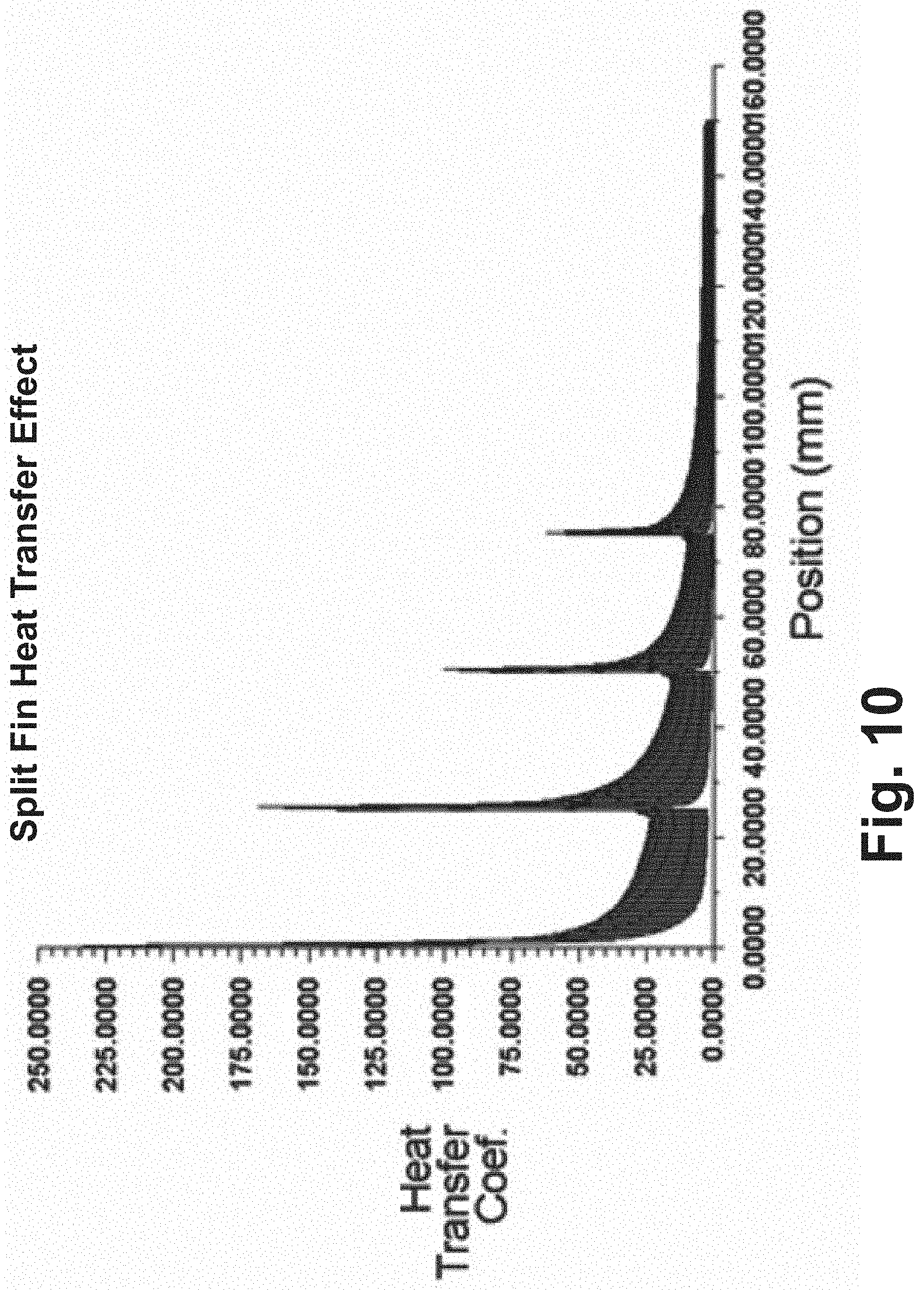
[0029] FIG. 10 plots heat transfer coefficient of an air cooled condenser fin with splits, versus position.
[0030] FIG. 11 plots heat transfer coefficient of an air cooled condenser fin with intermittent sinusoidal waves, versus position.
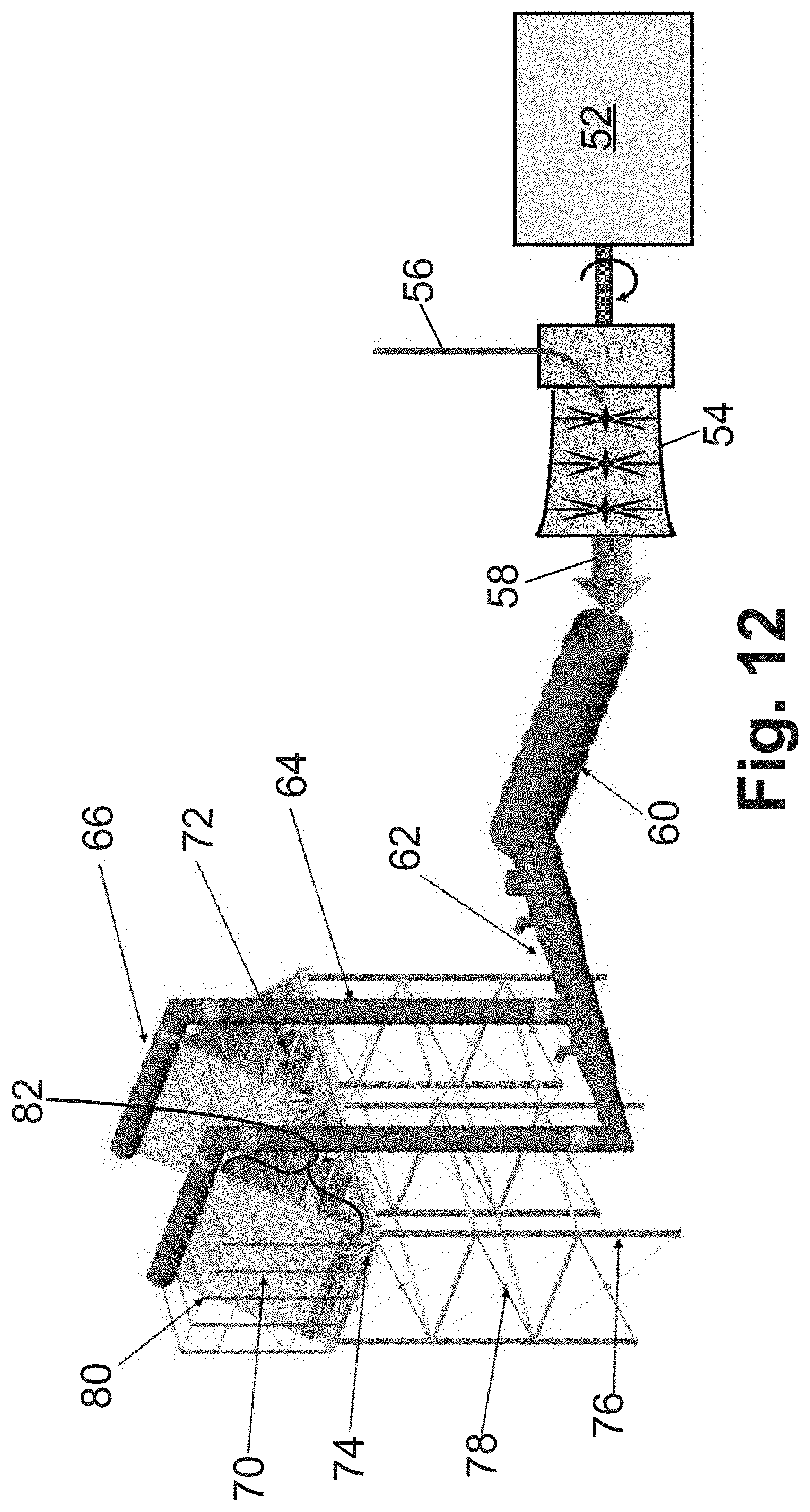
[0031] FIG. 12 diagrammatically shows a typical air cooled condenser application of the disclosed improved fins, where the illustrative air cooled condenser is of the forced draft A-frame type.
DETAILED DESCRIPTION OF THE PREFERRED EMBODIMENTS
[0032] For certain applications, such as air-cooled condensers, excessive pressure drop creates design constraints when applying fins to a tube geometry. A need exists for new and improved fin and fin array designs that minimize heat exchanger footprint opposite need for additional power input needed to move air/overcome excessive pressure drops of existing designs.
[0033] Air-cooled condenser applications have some requirements regarding the steam flow area and resultant pressure drop that places constraints on the minimum sizing of the heat exchanger fin tube base. Use of existing non-planar fin designs (Louvered, Offset, Wavy, etc.) requires additional power input (larger air mover sizing) to apply the fin to the required tube geometry. Further, redesigning tube geometry to incorporate a non-planar fin design in a lower power input design is often uneconomical.
[0034] Flow on the air-side of an air-cooled condenser generally operates in the laminar regime, which is defined by Reynolds numbers less than 2000. In this regime, momentum and energy transport occur via the mechanism of molecular diffusion, which is driven by gradients in the velocity profile. The velocity gradients near the fin wall are especially important in determining the momentum and energy transport rates in the local region as the air flows through the fin channel. As the air in the free-stream approach region enters the fin channels, extremely high velocity gradients result, based on the large velocity differential between the entering air velocity and the zero-velocity condition at the fin wall. This results in large friction factors and heat transfer coefficients at the lead edge of the fin. As the flow progresses down the fin channel, the velocity profile approaches the fully developed profile (generally parabolic). As this transition occurs, the local velocity gradients at the fin wall are reduced, and the local friction factor and heat transfer coefficient values gradually approach the fully developed values. This transition often occurs within ten (10) hydraulic diameters from the entrance to the fin section. The hydraulic diameter, D.sub.H, is a commonly used term when handling flow in non-circular tubes and channels, and is defined as
D H = 4 A P ( 1 ) ##EQU00001##
where A is the cross-sectional area of the flow and P is the wetted perimeter of the cross-section (where the wetted perimeter includes all surfaces acted upon by shear stress from the fluid). For a closed rectangular channel of dimensions a.times.b, the hydraulic diameter D.sub.H is given by:
D H , rect = 4 A P = 4 ( a .times. b ) a + b + a + b = 2 a b a + b ( 2 ) ##EQU00002##
The entrance region of the fin is therefore more effective in terms of heat transfer than the remainder of the fin, although the increase in heat transfer comes at the cost of added pressure drop.
[0035] With reference to FIGS. 1-3, numerical simulations of differential temperature versus length (FIG. 1), heat transfer coefficient versus length (FIG. 2), and incremental air pressure drop versus length (FIG. 3) are shown for a planar fin. In FIGS. 1, 2, and 3, the entrance region is to the left, with the air flow proceeding along the channel of length L to the exit side of the fin on the right of the curve. The most effective region of heat transfer in a planar fin of an air cooled condenser is at the air entrance into the fin channel. This is evident in FIG. 2 where the heat transfer coefficient decreases rapidly as air flows along the channel length.
[0036] FIG. 4 is a graphic representation showing a single split-fin 10 as disclosed herein. The split-fin takes advantage of the enhanced heat transfer which occurs at the lead edge of a fin channel entrance to reduce the total surface area of the overall fin assembly. The split-fin arrangement of FIG. 4 comprises a straight fin section 12 having a fin channel 14 that is subsequently split into two fin channels 16, 18 at a split point 20 along the length of the fin channel 14. The split 20 preferably occurs at or around the point where air flow has fully developed in the first channel section 14. As air flow (indicated by arrows F in FIG. 4) enters the staggered fin arrangement 20, it is split into subsequent sections, i.e. split air flows 16, 18. The fin wall of the downstream fin section 22 is located at or near the center of the upstream flow path or channel 14 (in other words, the staggering of the fin walls after the split is about one-half of a width of the air flow channel), thereby being exposed to high velocity gradients near the wall, similar to what occurs at the entrance of the first fin section 12. This process is repeated at each flow split, resulting in increased heat transfer at the lead edge region of every fin section 12, 22. A more compact fin assembly configuration results; requiring less fin surface area and comparatively less material needed to construct the fin array than traditional designs.
[0037] With reference to FIG. 5, when the split-fin is formed into a fin array, each flow split results in increased heat transfer coefficient and friction factor in the local region near the respective fin section entrance. FIG. 5 illustrates a fin array including successive illustrated fin sections 12a, 12b, 12c with respective channels 14a, 14b, 14c, with fin split point 20ab at the junction of fin sections 12a, 12b and fin split point 20bc at the junction of fin sections 12b, 12c. This is repeated for as many fin split sections exist in the assembly. The local increases in friction factor result in an increase in pressure drop, which is generally undesirable. Heat transfer from the fin to the air depends on two factors, the local heat transfer coefficient, and the local bulk air-to-fin temperature difference. The flow splits 20 increase the local heat transfer coefficient, which is beneficial. As with friction factor, the local increase in heat transfer coefficient resulting from each flow split 20 is consistent throughout the fin assembly. However, as the air flow F proceeds through the assembly, the temperature difference between the air and the fin is continuously reduced. Therefore, the effectiveness of the flow splits 20 with respect to increased local heat transfer decreases the farther the particular flow split is from the fin assembly entrance. For this reason, it is beneficial to cluster the flow splits 20 near the entrance to the assembly and use a more continuous section at the trail end of a fin assembly comprising multiple split-fins.
[0038] With reference to FIG. 6, in another embodiment, an air cooled condenser utilizes single row finned tubes and includes a split-feature within the air flow channel which disturbs the boundary layer along the flow channel wall. FIG. 6 shows a perspective view air flow velocity map for the split fin air flow.
[0039] The concepts of split-fins is not intended to be limited by the preceding discussion. Split features may be repeating or intermediate. Flow channel walls may be discontinuous or continuous. Flow along the wall of a planar fin may be perturbed by the channel being cut, and a new channel formed with the opening offset from the outlet of the original channel. Fin channels may consist of single or multiple splits.
[0040] Channel length of the fin sections 12 is preferably determined by finding the point along the wall in which the air flow boundary layer approaches fully developed profile. In one embodiment having multiple splits the splits are spaced between about 5 hydraulic diameters and about 10 hydraulic diameters apart.
[0041] With reference to FIG. 7, in an alternative embodiment one or more fin channels in the fin array may include intermittent sinusoidal waves. A graphic representation of a fin 30 having a channel 34 with an intermittent sinusoidal wave 32 is shown in FIG. 7. Flow F along the wall of the channel 34 is redirected by the sinusoidal wave 32 in the transverse direction of air flow F. Wave geometry of the sinusoidal wave 32 is designed to optimize full channel recirculation downstream from the disturbance. Planar fin wall is placed between the multiple waves 32 until boundary layer normalizes to reduce pressure drop. The sinusoidal waves 32 are preferably spaced between about 5 hydraulic diameters and about 10 hydraulic diameters apart.
[0042] With reference to FIGS. 8 and 9, in yet another embodiment, louvered fins 40 are disclosed. In this embodiment, openings 42 between adjacent fin channels 44 are used. Openings may take the form of louvers 46 angled between about 1 and about 30 degrees to the direction of flow. FIGS. 8 and 9 provide graphic representations of the openings 42 between adjacent fin channels 44. As seen in FIG. 8, the openings 42 do not comprise the entirely of the flow channel wall. While FIGS. 8 and 9 show alignment between openings in adjacent channels, such alignment is not present in some embodiments; rather, in these embodiments the opening may alternatively be offset. FIG. 8 also illustrates the louvered fins 40 soldered (or otherwise attached) to a tube 48 as is common in the case of an air cooled condenser (where the steam or other fluid being condensed flows through the tube 48). It is noted that FIGS. 8 and 9 show the louvers in the "pointing downstream" configuration. In this configuration the tips of the louvers are pointing roughly in the direction of the flow from upstream to downstream. In a variant embodiment, the louvers may be reversed, so as to point "into" the flow in the upstream direction. Either configuration can be employed effectively.
[0043] The innovations disclosed herein may be used on a single channel, a combination of channels, and/or combined with one another to form new and unique fin arrays that improve heat transfer over a variety of tube geometries that may be subject to space constraints and otherwise have limitations on ability to overcome pressure drop concerns. Further advantageous is the reduction in materials requirements for fin arrays enabled by the approaches disclosed herein.
[0044] FIGS. 10 and 11 plots show simulated data relating to heat transfer coefficient of the split-fin and intermittent wave, respectively, against position. As shown in these figures, the heat transfer peaks at the location of the flow interruption and decreases along the length of the channel as the boundary layer is reestablished and the difference in temperature between the two fluids, air and steam, is gradually reduced.
[0045] With reference now to FIG. 12, a typical air cooled condenser application of the disclosed improved fins is shown. An illustrative air cooled condenser shown in FIG. 12 is of the forced draft A-frame type. An electric power generator 52 is driven by a steam turbine 54 using steam 56. Exhaust steam 58 discharged from the steam turbine 54 flows into a main steam duct 60 and a distribution manifold 62, that distributes the steam to a set of air cooled condensers, an illustrative one of which is shown in FIG. 12. The steam flows up through risers 64 which are connected to feed the steam into distribution headers 66 which in turn are connected to feed the steam into bundles 70 that include steam/condensate tubes (e.g., the illustrative steam/condensate tube 48 shown in FIG. 8) with fins (such as split fins 10 as shown in FIGS. 4-6; or fins 30 with intermittent sinusoidal waves 32 as shown in FIG. 7; or fins 40 with louvers 46 as shown in FIGS. 8 and 9) soldered or otherwise attached to the steam/condensate tubes. An air moving system 72, such as a fan, drives an airflow across the fins of the bundles 70 in order to cool and condense the steam in the tubes to form condensate. FIG. 12 further shows the condenser superstructure including a fan deck 74 supported by support structure 76 and bracing 78, and a windwall structure 80 atop the fan deck 74. While the illustrative air cooled condenser is of the forced draft A-frame type, the disclosed improved fins are suitably employed in conjunction with air cooled condensers of other types, such as an induced draft V-frame condenser type, a flat condenser type, or so forth.
[0046] The inventors have performed computer simulations of the performance of various designs of split fins 10 (FIGS. 4-6), fins 30 with intermittent sinusoidal waves 32 (FIG. 7), and fins 40 with louvers 46 (FIGS. 8 and 9). In these simulations, the fins were modeled as rectangular channels with rectangular dimension H.sub.fin being the fin height (that is, the distance the fin extends away from the steam/condensate tube to which it is soldered) and dimension S.sub.fin being the separation between the fin walls defining the air flow channel. Using the hydraulic diameter for a rectangular channel given in Equation (2), this yields the following hydraulic diameter D.sub.H,fin for the fins:
D H , f i n = 4 A P = 2 a b a + b = 2 ( S f i n .times. H f i n ) S f i n + H f i n ( 3 ) ##EQU00003##
More generally, for an air flow channel of arbitrary cross sectional dimensions the first expression of Equation (3) holds, i.e.
D H , f i n = 4 A P ##EQU00004##
where A is the cross-sectional area of the air flow channel and P is the perimeter of the cross-section of the air flow channel, and with a tube bundle length "L" (also indicated as bundle length 82 if FIG. 12). The simulations were for a design of the bundles 70 that included 11 fins per inch. The simulations also modeled the energy (in horsepower which is related to pressure loss across a bundle) of the air moving system (e.g. fan) 72 and the bundle tube length 82. In addition to modeling performance of the designs of the split fins 10, fins 30 with intermittent sinusoidal waves 32, and louvered fins 40, simulations were performed to model the performance of conventional planar fin and continuous wavy fin designs. The simulations concluded that utilizing the planar fin design with the intermittent perforations, i.e., split fins 10, fins 30 with intermittent sinusoidal waves 32, and louvered fins 40 would enable reduction of the tube bundle length 82 by approximately 10% with only a moderate increase of 30% in the fan energy consumption (horsepower). The cost savings in reducing the tube bundle length by 10% is order magnitude greater than the cost of higher energy fan. On the other hand, the bundle with the continuous wavy fin design would reduce the tube bundle length by 16% but at the price of 700% increase in energy consumption which is prohibitive.
[0047] These simulations confirm the mechanism for improved performance disclosed herein, namely that employing mostly planar fins but with intermittent flow interruptions positioned at points where the boundary layer normalizes can achieve the desired heat transfer efficiency improvement while only imposing a modest increase in pressure drop. It was found that the intermittent flow interruptions are in some embodiments preferably spaced between about 5 hydraulic diameters and about 10 hydraulic diameters apart to optimally balance heat transfer efficiency (improved by the intermittent flow interruptions) against pressure drop introduced by the interruptions. The intermittent flow interruptions can be fin splits 20 (as in the embodiments of FIGS. 4-6), intermittent sinusoidal waves 32 (as in the embodiment of FIG. 7), louvers 46 (as in the embodiments of FIGS. 8 and 9), or more generally any other type of intermittent interruption. The simulations also found that placing the intermittent flow interruptions nearer the entrance side of the fin maximizes the heat transfer benefit while imposing the least additional pressure drop. For example, in some nonlimiting embodiments at least 70% of the intermittent flow interruptions are positioned within the first one-half of the fin length L (that is, within the half-fin length closest to the entrance side of the fin). In some other nonlimiting embodiments, at least 80% of the intermittent flow interruptions are positioned within the first one-third of the fin length L (that is, within the first third of the fin length that is closest to the entrance side of the fin).
[0048] It should be noted that the term "planar fin" is used herein in its usual and ordinary meaning in the art, as a fin that channels air flow principally along a single planar channel. In a planar section of a fin, the flow channel walls defining the air flow channel may have some deviations from geometrically perfect planar form, for example due to unintended manufacturing-induced variations, dimples, wall curvature, or so forth. Such a imperfections typically do not have a meaningful impact on air flow and hence are considered "planar" fin sections as used herein. Likewise, the term "intermittent flow interruption" as used herein is an intentional (i.e. design-basis) modification to a fin wall or walls, or a fin split, that is sufficient to induce air flow interruption as described herein. Hence, unintended manufacturing-induced variations, dimples, wall curvature, or so forth are not considered "intermittent flow interruptions" as used herein.
[0049] Illustrative embodiments including the preferred embodiments have been described. While specific embodiments have been shown and described in detail to illustrate the application and principles of the invention and methods, it will be understood that it is not intended that the present invention be limited thereto and that the invention may be embodied otherwise without departing from such principles. In some embodiments of the invention, certain features of the invention may sometimes be used to advantage without a corresponding use of the other features. Accordingly, all such changes and embodiments properly fall within the scope of the following claims. Obviously, modifications and alterations will occur to others upon reading and understanding the preceding detailed description. It is intended that the present disclosure be construed as including all such modifications and alterations insofar as they come within the scope of the appended claims or the equivalents thereof.
* * * * *
D00000
D00001
D00002
D00003
D00004
D00005
D00006
D00007
D00008
D00009
D00010
D00011
D00012


XML
uspto.report is an independent third-party trademark research tool that is not affiliated, endorsed, or sponsored by the United States Patent and Trademark Office (USPTO) or any other governmental organization. The information provided by uspto.report is based on publicly available data at the time of writing and is intended for informational purposes only.
While we strive to provide accurate and up-to-date information, we do not guarantee the accuracy, completeness, reliability, or suitability of the information displayed on this site. The use of this site is at your own risk. Any reliance you place on such information is therefore strictly at your own risk.
All official trademark data, including owner information, should be verified by visiting the official USPTO website at www.uspto.gov. This site is not intended to replace professional legal advice and should not be used as a substitute for consulting with a legal professional who is knowledgeable about trademark law.