Method And Device For Separating Air By Cryogenic Distillation
DUBETTIER-GRENIER; Richard ; et al.
U.S. patent application number 16/755821 was filed with the patent office on 2020-10-22 for method and device for separating air by cryogenic distillation. The applicant listed for this patent is L'Air Liquide, Societe Anonyme pour I'Etude et I'Exploitation des Precedes Georges Claude. Invention is credited to Richard DUBETTIER-GRENIER, Patrick LE BOT.
| Application Number | 20200333069 16/755821 |
| Document ID | / |
| Family ID | 1000004955527 |
| Filed Date | 2020-10-22 |


| United States Patent Application | 20200333069 |
| Kind Code | A1 |
| DUBETTIER-GRENIER; Richard ; et al. | October 22, 2020 |
METHOD AND DEVICE FOR SEPARATING AIR BY CRYOGENIC DISTILLATION
Abstract
A method for separating air by cryogenic distillation, wherein air is compressed in a first compressor, cooled in a heat exchanger and then separated in a system of columns, liquid oxygen is vaporized in the heat exchanger countercurrent to a flow of pressurized gas which pseudo-condenses, a flow of gas which is air or a gas delivered from the system of columns is expanded in a cryogenic expansion turbine having a single wheel, the turbine having an inlet temperature lower than -100.degree. C., a gas which is air or a gas delivered from the system of columns is compressed in a first booster compressor having a single wheel, with an inlet temperature higher than -50.degree. C., a gas which is air or a gas delivered from the system of columns.
| Inventors: | DUBETTIER-GRENIER; Richard; (La Varenne Saint Hilaire, FR) ; LE BOT; Patrick; (Vincennes, FR) | ||||||||||
| Applicant: |
|
||||||||||
|---|---|---|---|---|---|---|---|---|---|---|---|
| Family ID: | 1000004955527 | ||||||||||
| Appl. No.: | 16/755821 | ||||||||||
| Filed: | August 30, 2018 | ||||||||||
| PCT Filed: | August 30, 2018 | ||||||||||
| PCT NO: | PCT/FR2018/052130 | ||||||||||
| 371 Date: | April 13, 2020 |
| Current U.S. Class: | 1/1 |
| Current CPC Class: | F25J 2240/04 20130101; F25J 2230/20 20130101; F25J 3/04412 20130101; F25J 3/04024 20130101; F25J 3/04393 20130101; F25J 3/04309 20130101; F25J 3/0406 20130101; F25J 3/0409 20130101; F25J 3/04381 20130101; F25J 3/04054 20130101; F25J 3/04351 20130101 |
| International Class: | F25J 3/04 20060101 F25J003/04 |
Foreign Application Data
| Date | Code | Application Number |
|---|---|---|
| Oct 13, 2017 | FR | 1701070 |
Claims
1.-15. (canceled)
16. A method for separating air by cryogenic distillation, wherein air is compressed in a first compressor, cooled in a heat exchanger and then separated in a system of columns, liquid oxygen is vaporized in the heat exchanger countercurrent to a flow of pressurized gas which pseudo-condenses, a flow of gas which is air or a gas delivered from the system of columns is expanded in a cryogenic expansion turbine having a single wheel, the turbine having an inlet temperature lower than -100.degree. C., a gas which is air or a gas delivered from the system of columns is compressed in a first booster compressor having a single wheel, with an inlet temperature higher than -50.degree. C., a gas which is air or a gas delivered from the system of columns, this gas having already been compressed in the first booster compressor, is compressed in a second booster compressor having a single wheel with an inlet temperature lower than -100.degree. C., the gas compressed in at least the first booster compressor cools in the heat exchanger, contributes to the vaporization of liquid oxygen by exchange of heat in the exchanger, and is pseudo-liquefied on leaving the cold end of the heat exchanger, wherein: a) the work generated by the expansion turbine is used for the compression step in the first booster compressor and for the compression step in the second booster compressor, b) the operating conditions for the wheel of the expansion turbine, the wheel of the first booster compressor and the wheel of the second booster compressor are defined such that these three wheels have the same rotational speed, c) i) the wheel of the first booster compressor, the wheel of the second booster compressor and the wheel of the turbine are mounted on the same rotation shaft, or ii) the first and the second booster compressor are connected to the wheel of the expansion turbine, each by a rotation shaft, these shafts rotating at the same rotational speed, or iii) the first booster compressor and the wheel of the expansion turbine are connected to the second booster compressor, each by a rotation shaft, these shafts rotating at the same rotational speed, and d) the first compression step allows work to be generated outside the cold box, and this generates cooling power for the air separation method.
17. The method as claimed in claim 16, comprising a second expansion turbine, wherein the first expansion turbine and the second expansion turbine operate in parallel and the flow of gas which is air or a gas delivered from the system of columns is divided into two fractions, each being expanded in one of the two turbines.
18. The method as claimed in claim 17, wherein, of the expansion wheel, the wheel of the second expansion turbine, the wheel of the first booster compressor and the wheel of the second booster compressor, at least one has an efficiency lower than that which it would have, under the same operating conditions, at another rotational speed.
19. The method as claimed in claim 16, wherein the gas compressed in the first and the second booster compressor is air used for distillation.
20. The method as claimed in claim 16, wherein at least some of the air, or even all of the air or at least some of the gas, or even all of the gas, compressed in the first booster compressor is then compressed in the second booster compressor.
21. The method as claimed in claim 16, wherein the work produced by the turbine is not transferred to a generator, to an oil brake or to a compressor other than the first and second booster compressors.
22. The method as claimed in claim 16, wherein the inlet temperature of the turbine is lower than the inlet temperature of the second booster compressor and/or the inlet temperature of the first booster compressor.
23. The method as claimed in claim 16, wherein the air is compressed first in the first booster compressor and then in the second booster compressor.
24. The method as claimed in claim 23, wherein all the air compressed in the first booster compressor is then compressed in the second booster compressor.
25. The method as claimed in claim 16, wherein the air expanded in the turbine has been compressed in the first booster compressor.
26. The method as claimed in claim 25, wherein the air expanded in the turbine has already been compressed in the first booster.
27. The method as claimed in claim 16, wherein the air expanded in the turbine has not been compressed in the first or the second booster compressor.
28. A apparatus for separating air by cryogenic distillation, comprising a heat exchanger, a pipe for sending air compressed in a first compressor to be cooled in the heat exchanger, a system of columns, a pipe for sending the air cooled in the heat exchanger to be separated in the system of columns, a pipe for sending liquid oxygen from the system to be vaporized in the heat exchanger, a pipe for sending a flow of pressurized gas into the heat exchanger, a cryogenic expansion turbine having a single wheel, a pipe connected to an intermediate point of the heat exchanger for sending a flow of gas which is air or a gas delivered from the system of columns from the heat exchanger to be expanded in the cryogenic expansion turbine, the turbine having an inlet temperature lower than -100.degree. C., a first single-stage booster compressor with an inlet temperature higher than -50.degree. C., a pipe for sending a gas which is air or a gas delivered from the system of columns, to be compressed in the first booster compressor, a second single-stage booster compressor with an inlet temperature lower than -100.degree. C., a pipe connected to an intermediate point of the heat exchanger for sending a gas which is air or a gas delivered from the system of columns to be compressed in the second booster compressor, a means for sending at least some of the gas, or even all of the gas, compressed in the first booster compressor to be compressed in the second booster compressor), a pipe for sending the gas compressed in at least the first booster compressor to be cooled in the heat exchanger and thus contribute to the vaporization of liquid oxygen by exchange of heat in the exchanger, wherein: a) the wheel of the expansion turbine, possibly the wheel of the second turbine, the wheel of the first booster compressor and the wheel of the second compressor are connected to one another in such a way that each wheel can have the same rotational speed, and b) i) the wheel of the first booster compressor, the wheel of the second booster compressor and the wheel of the turbine is mounted on the same rotation shaft, or ii) the first and the second booster compressor are connected to the wheel of the expansion turbine, and possibly to the wheel of the second turbine, each by a rotation shaft, these shafts being capable of rotating at the same rotational speed, or iii) the first booster compressor and the wheel of the expansion turbine are connected to the second booster compressor, each by a rotation shaft, these shafts being capable of rotating at the same rotational speed.
29. The apparatus as claimed in claim 28, wherein the gas compressed in the first and the second booster compressor is air intended for distillation.
30. The apparatus as claimed in claim 28, comprising a means for sending at least some of the air, or even all of the air, compressed in the first booster compressor to be compressed in the second booster compressor.
Description
CROSS REFERENCE TO RELATED APPLICATIONS
[0001] This application is a 371 of International Application PCT/FR2018/052130, filed Aug. 30, 2018, which claims priority to French Patent Application No. 1701070, filed Oct. 13, 2017, the entire contents of which are incorporated herein by reference.
BACKGROUND
[0002] The present invention relates to a method and an apparatus for separating air by cryogenic distillation.
[0003] Air separation units (ASU) for separating air by cryogenic distillation using cryogenic compression of a gas are known. One known means for implementing this cold compression is to drive a cryogenic-compression wheel using a cryogenic expansion turbine. Nevertheless, such equipment does not generate the production of coldness needed for the operation of air separation units because no work is extracted from the cold box. For that reason, such systems are always coupled to an additional means for producing cold. The known means are: [0004] Oil brake: The work is extracted by the viscous friction between the rotational shaft and a film of pressurized oil contained in a cavity around the shaft. This friction causes the oil to heat up, which oil is cooled outside of the system in order to remove the work. This system has the disadvantage of implementability and efficiency. Specifically, the work generated is lost and detracts from the efficiency of the whole. Furthermore, the system is limited in terms of the extracted power (approx. 100 kW) and is therefore not suitable for ASUs that require a higher cooling power. [0005] Compressor brake and refrigerant: In this method, another assembly comprising another turbine coupled to a compressor is used to supplement the assembly of a turbine having a cryogenic outlet temperature coupled to a compressor having a cryogenic booster inlet temperature. The turbine is therefore coupled to a compressor the intake temperature of which is ambient or slightly below ambient. Compressing the gas heats same and the gas is cooled in a heat exchanger (typically against water) in order to extract heat, and therefore work, therefrom. This is the means most commonly used in the field of ASUs. [0006] Generator: The expansion turbine may also be coupled to a generator which extracts work by generating electrical energy which is sent to a network. The rotational speed of this generator is most often very much lower than the rotational speed of the turbine, requiring a reduction gearbox between the two elements. This component is expensive and generates friction losses. Generators with high rotational speeds are also found. This generator is then integrated onto the turbine shaft and generates electricity without the need for an intermediate reduction gearbox. A system for processing the electric signal (frequency, etc. . . . ) is then needed in order to make it compatible with the specifications of the electrical networks to which it can then be sent on. These systems are very expensive and also limited in terms of generated power (approx. 250 kW) and are unable to fully meet the needs of the ASUs.
[0007] Furthermore, it is also known practice to be able to couple a combination of compressors and turbines on the one same shaft. Drives will be encountered for example where compressors are driven by a gas turbine, having a hot gas turbine driving its air compressor and another product compressor. However, these arrangements, however complex they might be, are not applicable to cryogenic use: different types of turbines, below-ambient temperatures, no criticality regarding thermal losses.
SUMMARY
[0008] According to the invention, in an air separation unit separating air by cryogenic distillation, two compressed flows are generated, characterized in that: [0009] each compression is achieved in a single-stage compression stage, [0010] the two compression stages are driven by the one same cryogenic expansion turbine, [0011] the first compression step, from a temperature close to ambient temperature, allows work to be generated outside the cold box, and this generates cooling power for the air separation method, [0012] the second compression step is a cryogenic compression, which compresses a gas drawn off from an intermediate level of the main exchanger at a first temperature which is a cryogenic temperature, and returned to the main exchanger at a temperature higher than the first temperature.
[0013] In one preferred implementation, the two compression steps will be arranged in series on the same flow. As a preference, this flow will be part of the total airflow, which will first of all be compressed from ambient temperature, then when cold. This flow, after having been reintroduced into the main exchanger, will travel as far as the cold end of the exchanger where it will be (pseudo) liquefied.
[0014] According to the invention, the turbine wheel and the wheels of the booster compressors rotate at the same rotational speed.
[0015] Surprisingly, that makes it possible to maintain acceptable thermodynamic efficiencies in the compression steps and in the expansion step, despite the three wheels having the same rotational speed. By comparison with the prior art which consisted in using two turbine and booster assemblies, it becomes possible thanks to the invention to reduce the investment costs thereof without dramatically penalizing the efficiency of the method.
[0016] The invention will be described in more detail with reference to the figures which depict methods according to the invention.
[0017] One subject matter of the invention provides a method for separating air by cryogenic distillation, wherein air is compressed in a first compressor, cooled in a heat exchanger and then separated in a system of columns, liquid oxygen is vaporized in the heat exchanger countercurrent to a flow of pressurized gas which (pseudo) condenses, a flow of gas which is air or a gas delivered from the system of columns is expanded in a cryogenic expansion turbine having a single wheel, having an inlet temperature lower than -100.degree. C., a gas which is air or a gas delivered from the system of columns, this gas having already been compressed in the first booster compressor, is compressed in a first booster compressor having a single wheel with an inlet temperature higher than -50.degree. C., a gas which is air or a gas delivered from the system of columns is compressed in a second booster compressor having a single wheel with an inlet temperature lower than -100.degree. C., the gas compressed in at least the first booster compressor cools in the heat exchanger, contributes to the vaporization of liquid oxygen by exchange of heat in the exchanger, and is (pseudo) liquefied on leaving the cold end of the heat exchanger, wherein: [0018] a) the work generated by the expansion turbine is used for the cryogenic compression step in the first booster compressor and for the compression step in the second booster compressor, and [0019] b) the operating conditions for the wheel of the expansion turbine, the wheel of the first booster compressor and the wheel of the second booster compressor are defined to allow these three wheels to have the same rotational speed, and [0020] c) i) the wheel of the first booster compressor, the wheel of the second booster compressor and the wheel of the turbine are mounted on the same rotation shaft, or [0021] ii) each booster compressor is connected to the wheel of the turbine by a rotation shaft, these shafts rotating at the same rotational speed, or [0022] iii) the first booster compressor and the wheel of the expansion turbine are connected to the second booster compressor, each by a rotation shaft, these shafts rotating at the same rotational speed, and [0023] d) the first compression step allows work to be generated outside the cold box, and this generates cooling power for the air separation method.
[0024] According to other optional aspects: [0025] of the expansion wheel, the wheel of the first booster compressor and the wheel of the second booster compressor, at least one has an efficiency lower than that which it would have, under the same operating conditions, at another rotational speed. [0026] the gas compressed in the first and the second booster compressor is air intended for distillation. [0027] at least some of the air, or even all of the air or at least some of the gas, or even all of the gas, compressed in the first booster compressor is then compressed in the second booster compressor. [0028] the work produced by the turbine is not transferred to a generator, to an oil brake or to a compressor other than the first and second booster compressors. [0029] the inlet temperature of the turbine is lower than the inlet temperature of the second booster compressor and/or the inlet temperature of the first booster compressor. [0030] the air is compressed first of all in the first booster compressor and then in the second booster compressor. [0031] all of the air compressed in the first booster compressor is then compressed in the second booster compressor. [0032] the air expanded in the turbine has been compressed in the first booster compressor. [0033] the air expanded in the turbine has been compressed in the first booster compressor and possibly in the second booster compressor. [0034] the air expanded in the turbine has not been compressed in the first or the second booster compressor.
[0035] Another aspect of the invention provides an apparatus for separating air by cryogenic distillation, comprising a heat exchanger, a pipe for sending air compressed in a first compressor to be cooled in the heat exchanger, a system of columns, a pipe for sending the air cooled in the heat exchanger to be separated in the system of columns, a pipe for sending liquid oxygen from the system to be vaporized in the heat exchanger, a pipe for sending a flow of pressurized gas into the heat exchanger, a cryogenic expansion turbine having a single wheel, a pipe connected to an intermediate point of the heat exchanger for sending a flow of gas which is air or a gas delivered from the system of columns from the heat exchanger to be expanded in the cryogenic expansion turbine, having an inlet temperature lower than -100.degree. C., a first single-stage booster compressor with an inlet temperature higher than -50.degree. C., a pipe, possibly connected to an intermediate point of the heat exchanger, for sending a gas which is air or a gas delivered from the system of columns, to be compressed in the first booster compressor, a second single-stage booster compressor with an inlet temperature lower than -100.degree. C., a pipe connected to an intermediate point of the heat exchanger for sending a gas which is air or a gas delivered from the system of columns to be compressed in the second booster compressor, where appropriate, means for sending at least some of the gas, or even all of the gas, compressed in the first booster compressor to be compressed in the second booster compressor, a pipe for sending the gas compressed in at least the first booster compressor to be cooled in the heat exchanger and thus contribute to the vaporization of liquid oxygen by exchange of heat in the exchanger, wherein: [0036] a) the wheel of the expansion turbine, the wheel of the first booster compressor and the wheel of the second compressor are connected to one another in such a way that each wheel can have the same rotational speed, and [0037] b) the wheel of the first booster compressor, the wheel of the second booster compressor and the wheel of the turbine being mounted on the same rotation shaft or each booster compressor is connected to the wheel of the turbine by a rotation shaft, these shafts being designed to rotate at the same rotational speed.
[0038] According to other optional aspects: [0039] the method uses the second expansion turbine, the two turbines operating in parallel and the flow of gas which is air or a gas delivered from the system of columns is divided into two fractions, each being expanded in one of the two turbines. [0040] the gas compressed in the first and the second booster compressor is air intended for distillation. [0041] the apparatus comprises means for sending at least some of the air, or even all of the air or at least some of the gas, or even all of the gas, compressed in the first booster compressor to be compressed in the second booster compressor. [0042] the turbine is not coupled to a generator, to an oil brake or to a compressor other than the first and second booster compressors. [0043] the apparatus comprises just one single turbine. [0044] the apparatus comprises means for sending air from the first booster compressor and possibly from the second booster compressor to the turbine.
BRIEF DESCRIPTION OF THE DRAWINGS
[0045] For a further understanding of the nature and objects for the present invention, reference should be made to the following detailed description, taken in conjunction with the accompanying drawings, in which like elements are given the same or analogous reference numbers and wherein:
[0046] FIG. 1 is a symbolic representation of a method for separating air by cryogenic distillation in a double column having an optional minaret, in accordance with one embodiment of the present invention.
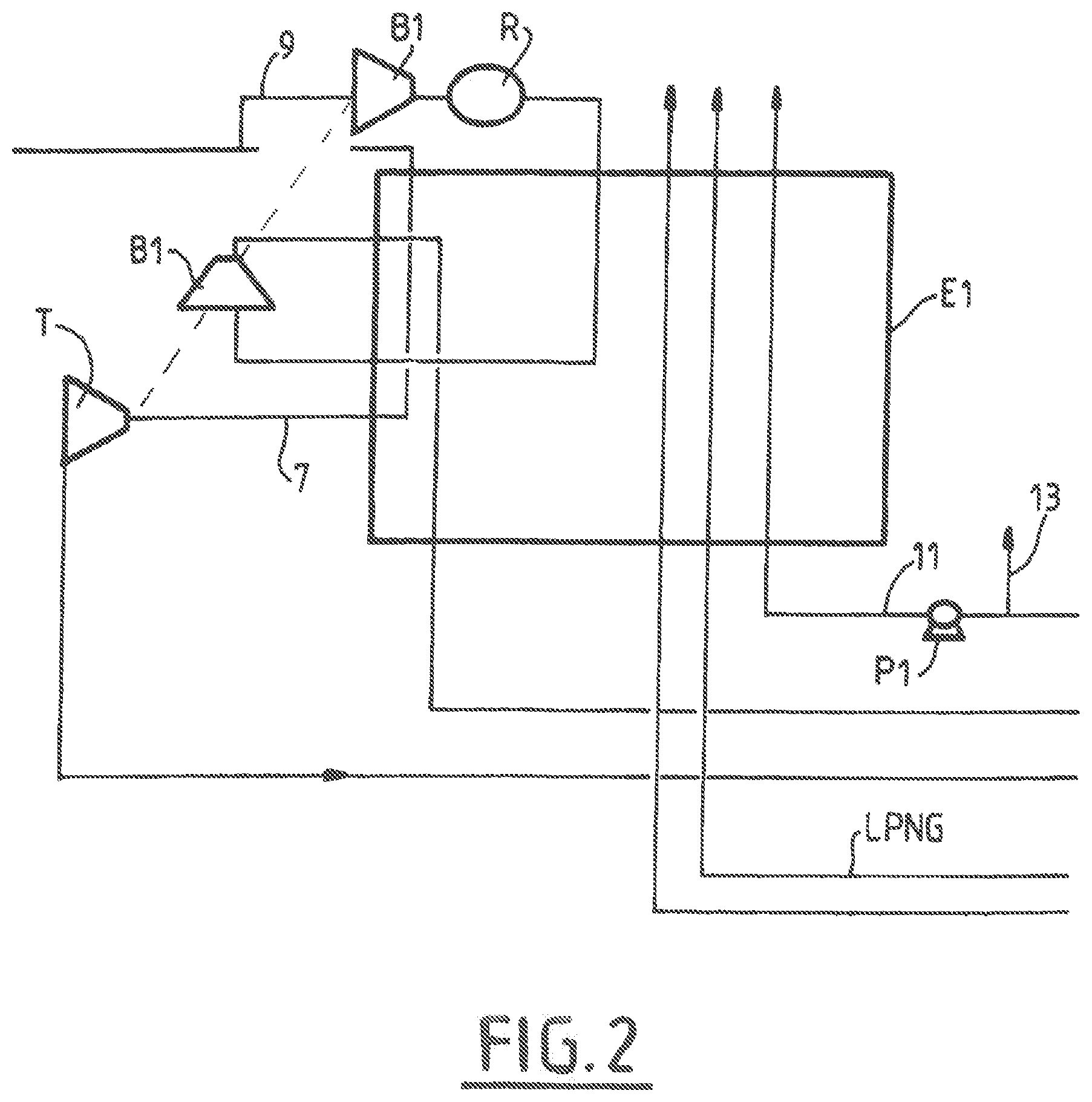
[0047] FIG. 2 is a symbolic representation of a method of separating air by cryogenic distillation in a double column system wherein two booster compressors are used, in accordance with one embodiment of the present invention.
DETAILED DESCRIPTION OF PREFERRED EMBODIMENTS
[0048] A flow of air compressed to the pressure of the first column, denoted by the reference MP, from the double column is split into two. A flow 3 is cooled in a main heat exchanger E1 and is sent to the first column MP. The rest 5 of the air is compressed in an auxiliary booster compressor S and cooled in a cooler R before being split into two. A part, 7, of the air is sent to the main heat exchanger E1 where it is cooled down to an intermediate temperature of this exchanger which is lower than -100.degree. C. At this temperature, the flow 7 is sent to a turbine T where it is expanded to the pressure of the first column before being mixed with the flow 3 and sent to the first column.
[0049] Another part, 9, of the air from the booster compressor S is sent to a first booster compressor B1 without having been cooled in the heat exchanger E1. The air 9 is then cooled in a cooler before being sent to the hot end of the heat exchanger where it is cooled to an intermediate temperature of the heat exchanger which is nevertheless higher than the inlet temperature of the turbine T. The air 9 leaves the exchanger E1 at this intermediate temperature and is compressed in a second booster compressor B2. The compressed air is returned to the exchanger E1 at a temperature higher either than the intermediate temperature or the inlet temperature of the turbine T. The air compressed in B2 continues to be cooled in the heat exchanger E1 as far as the cold end and is expanded in a valve V to return to the column MP in liquid or pseudo-condensed form. A part of this expanded liquid may also be returned to the low-pressure column BP.
[0050] The first and second booster compressors are both single-stage booster compressors having just one compression wheel.
[0051] The wheel of the first booster compressor B1, the wheel of the second booster compressor B2 and the wheel of the turbine T are mounted on the same rotation shaft, or on securely connected shafts.
[0052] The turbine T is not coupled either to a generator or to an oil brake. It drives only the first and second booster compressors B1, B2.
[0053] The first booster compressor B1 has an inlet temperature higher than -50.degree. C., possibly higher than 0.degree. C., preferably higher than 10.degree. C. The second booster compressor B2 has an inlet temperature lower than -100.degree. C.
[0054] A liquid enriched in oxygen and a liquid enriched in nitrogen are sent from the first column MP to the second column, denoted by the reference BP, as reflux liquids. An overhead gas of the first column condenses in a bottom condenser of the second column and is condensed and returned to the first column.
[0055] In the method of FIG. 2, just two booster compressors are used. The air flow 1 compressed to a pressure at least 5 bar higher than the pressure of the first column is divided into two parts 7, 9. The part 7 is sent to the main heat exchanger E1 where it is cooled down to an intermediate temperature of this exchanger which is lower than -100.degree. C. At this temperature, the flow 7 is sent to a turbine T where it is expanded to the pressure of the first column. The part 9 of the air is compressed in a second booster compressor B2. The compressed air is sent, after having been cooled in a water refrigerant, to the hot end of the heat exchanger E1 where it is cooled to an intermediate temperature of the exchanger which is nevertheless higher than or equal to the inlet temperature of the turbine T. The air 9 leaves the exchanger E1 at this intermediate temperature and is compressed in a second booster compressor B2. The compressed air is returned to the exchanger E1 at a temperature higher than the inlet temperature of the turbine T. The air compressed in B2 continues to be cooled in the heat exchanger E1 as far as the cold end and is expanded in a valve to return to the column MP in liquid or pseudo-condensed form. A part of this expanded liquid may also be returned to the low-pressure column BP.
[0056] The first and second booster compressors are both single-stage booster compressors B1, the wheel of the second booster compressor B2 and the wheel of the turbine T are mounted on the same rotation shaft, or on securely connected shafts.
[0057] The turbine T is not coupled either to a generator or to an oil brake. It drives only the first and second booster compressors B1, B2.
[0058] The first booster compressor B1 has an inlet temperature higher than 0.degree. C. The second booster compressor B2 has an inlet temperature lower than -100.degree. C.
[0059] In the two figures, the work generated by the expansion turbine is used for the cryogenic compression step in the first booster compressor and for the compression step in the second booster compressor.
[0060] The operating conditions for the wheel of the expansion turbine T, the wheel of the first booster compressor B1 and the wheel of the second booster compressor B2 are defined to allow these three wheels to have the same rotational speed.
[0061] The wheel of the first booster compressor B1, the wheel of the second booster compressor B2 and the wheel of the turbine T are mounted on the same rotation shaft in the figures.
[0062] Otherwise, each booster compressor may be connected to the wheel of the turbine by a rotation shaft, these shafts rotating at the same rotational speed.
[0063] Of the expansion wheel, the wheel of the first booster compressor and the wheel of the second booster compressor, at least one has an efficiency lower than that which it would have, under the same operating conditions, at another rotational speed.
[0064] At least one, or even at least two, or even all of the wheels do not operate at their optimal efficiency.
[0065] It will be appreciated that the invention also applies to instances in which a flow of nitrogen or another gas originating from distillation is compressed in a first booster compressor having an inlet temperature higher than -50.degree. C. and a second booster compressor having an inlet temperature lower than -100.degree. C.
[0066] It will be understood that many additional changes in the details, materials, steps and arrangement of parts, which have been herein described in order to explain the nature of the invention, may be made by those skilled in the art within the principle and scope of the invention as expressed in the appended claims. Thus, the present invention is not intended to be limited to the specific embodiments in the examples given above.
* * * * *
D00000
D00001
D00002
D00003
D00004
XML
uspto.report is an independent third-party trademark research tool that is not affiliated, endorsed, or sponsored by the United States Patent and Trademark Office (USPTO) or any other governmental organization. The information provided by uspto.report is based on publicly available data at the time of writing and is intended for informational purposes only.
While we strive to provide accurate and up-to-date information, we do not guarantee the accuracy, completeness, reliability, or suitability of the information displayed on this site. The use of this site is at your own risk. Any reliance you place on such information is therefore strictly at your own risk.
All official trademark data, including owner information, should be verified by visiting the official USPTO website at www.uspto.gov. This site is not intended to replace professional legal advice and should not be used as a substitute for consulting with a legal professional who is knowledgeable about trademark law.