Axial Piston Device
Hemink; Douglas A.
U.S. patent application number 16/917258 was filed with the patent office on 2020-10-22 for axial piston device. This patent application is currently assigned to Torvec, Inc.. The applicant listed for this patent is Torvec, Inc.. Invention is credited to Douglas A. Hemink.
| Application Number | 20200332782 16/917258 |
| Document ID | / |
| Family ID | 1000004929410 |
| Filed Date | 2020-10-22 |


View All Diagrams
| United States Patent Application | 20200332782 |
| Kind Code | A1 |
| Hemink; Douglas A. | October 22, 2020 |
AXIAL PISTON DEVICE
Abstract
An axial piston device may be operated as a pump and includes a self-centering rotary valve. The device includes a stationary housing encompassing a shaft and the rotary valve. The rotary valve and the shaft are coupled to each other. Upon rotation, the rotary valve self-centers as a result of elimination of moments and forces within the pump. The inventive pump is a piston device. The valve is within a valve bore, which is a part of a manifold. A shaft is within the manifold and the shaft is attached at its distal end to a planar surface of the rotary valve. The shaft has a first axis of rotation and the rotary valve has a second axis of rotation. During operation of the pump, the first axis is often times offset from the second axis. The pump operates via a swashplate with reciprocating pistons while the housing remains stationary.
| Inventors: | Hemink; Douglas A.; (Churchville, NY) | ||||||||||
| Applicant: |
|
||||||||||
|---|---|---|---|---|---|---|---|---|---|---|---|
| Assignee: | Torvec, Inc. Rochester NY |
||||||||||
| Family ID: | 1000004929410 | ||||||||||
| Appl. No.: | 16/917258 | ||||||||||
| Filed: | June 30, 2020 |
Related U.S. Patent Documents
| Application Number | Filing Date | Patent Number | ||
|---|---|---|---|---|
| 15116695 | Aug 4, 2016 | |||
| PCT/US2015/014630 | Feb 15, 2015 | |||
| 16917258 | ||||
| 62093146 | Dec 17, 2014 | |||
| 61937166 | Feb 7, 2014 | |||
| Current U.S. Class: | 1/1 |
| Current CPC Class: | F04B 1/16 20130101; F04B 53/1087 20130101; F04B 1/295 20130101; F04B 11/0091 20130101; F04B 53/10 20130101; F04B 1/126 20130101; F04B 1/146 20130101; F04B 1/143 20130101; F04B 1/141 20130101 |
| International Class: | F04B 1/141 20060101 F04B001/141; F04B 53/10 20060101 F04B053/10; F04B 1/16 20060101 F04B001/16; F04B 1/126 20060101 F04B001/126; F04B 1/143 20060101 F04B001/143; F04B 1/146 20060101 F04B001/146; F04B 1/295 20060101 F04B001/295; F04B 11/00 20060101 F04B011/00 |
Claims
1. A piston device comprising: a stationary cylinder block, a shaft that is rotatable about its own axis within the stationary cylinder block, and the shaft comprising a plurality of passages configured to receive, direct and exhaust fluid, the shaft centrically and eccentrically rotatable during operation of the pump, and a swash plate coupled to the shaft, the swash plate having a first side coupled to a first plurality of pistons.
2. The piston device as recited in claim 1 wherein the swash plate is configured to tilt about an axis perpendicular to the axis of the shaft.
3. The piston device as recited in claim 2 further comprising a means for tilting the swash plate.
4. The piston device as recited in claim 1 wherein fluid pressure on the passages in the shaft balances at least one force and/or moment.
5. The piston device as recited in claim 1 further comprising a respective plurality of slipper shoes each connected to a piston, and the swash plate comprising at least one active surface for interacting with the slipper shoes.
6. The piston device as recited in claim 1 wherein fluid flow throughout the pump creates at least one of a force and a moment on the shaft and the plurality of passages are configured on the shaft such that at least one of the forces or the moments on the shaft are balanced.
7. The piston device as recited in claim 6 further comprising a second plurality of pistons, each plurality of pistons contained within the cylinder block and arcuately positioned coaxial with the shaft on opposite ends of the cylinder block.
8. The piston device as recited in claim 7 further comprising a first active surface and a second active surface, the first and second active surfaces are on opposing sides of the swash plate.
9. A piston device comprising: a stationary cylinder block; a shaft extending through the stationary cylinder block and having a plurality of passages along a portion of the shaft; and a valve enclosed within the stationary cylinder block, the valve comprising the shaft integrally coupled to the valve.
10. The piston device as recited in claim 9 further comprising a first plurality of pistons and a second plurality of pistons, each plurality of pistons arcuatley positioned coaxial with the shaft on opposite sides of the shaft.
11. The piston device as recited in claim 9 wherein the plurality of passages are configured to receive, direct and exhaust fluid flow throughout the pump.
12. The piston device as recited in claim 11 wherein the fluid flow throughout the pump creates at least one of a plurality of forces and a plurality of moments on the shaft and the plurality of passages are configured on the shaft such that the at least one of the plurality of forces and the plurality of moments is balanced.
13. The piston device as recited in claim 12 further comprising a plurality of slipper assemblies, each slipper assembly coupled to one piston of the plurality of pistons; and a swash plate coupled to the shaft and comprising at least one active surface for interacting with a respective slipper assembly.
14. The piston device as recited in claim 13 further comprising a first active surface and a second active surface, the first and second active surfaces are on opposing sides of the swash plate.
15. A piston device comprising: a swash plate having a first side coupled to a first plurality of slipper shoes and a second side coupled to a second plurality of slipper shoes, the first side of the swash plate is generally parallel to the second side of the swash plate; and a first portion of the pump on the first side of the swash plate and a second portion of the pump on the second side of the swash plate, the first portion of the pump on the first side of the swash plate is substantially symmetric about the swash plate with the second portion of the pump.
16. The piston device as recited in claim 15 further comprising a shaft, the swash plate coupled to the shaft
17. The piston device as recited in claim 16 configured to be adjustable about an axis askew or perpendicular to an axis of the shaft.
18. The piston device as recited in claim 16 further comprising a means for balancing at least one of a plurality of forces and a plurality of moments acting on the shaft.
19. The piston device as recited in claim 17 further comprising a means for tilting the swash plate with respect to the shaft.
20. The piston device as recited in claim 16 further comprising a housing encasing the shaft, swash plate and slipper assemblies.
Description
CROSS-REFERENCE TO RELATED APPLICATIONS
[0001] This application is a continuation of U.S. Ser. No. 15/116,695 filed on Aug. 4, 2016, which is the U.S. National Phase Application of PCT International Application No. PCT/US2015/014630, filed Feb. 5, 2015, which claims the benefit of U.S. Provisional Patent Application No. 61/937,166 filed Feb. 7, 2014 and U.S. Provisional Patent Application No. 62/093,146 filed Dec. 17, 2014, the contents of such applications being incorporated by reference herein.
TECHNICAL FIELD
[0002] This disclosure relates to fluid power and more particularly relates to the displacement of fluid via an axial piston device.
BACKGROUND OF THE INVENTION
[0003] Axial piston technology is typically embodied in non-rotating cylinder block and rotating cylinder block devices (e.g. rotating cylinder block style hydraulic pump/motor; commonly referred to as a "rotating group"). A conventional non-rotating cylinder block pump is shown in FIG. 1 and a rotating cylinder block pump is shown in FIG. 2.
[0004] Non-rotating cylinder blocks experience problems with forces on the pump's shaft and swash plate. Those forces have to be carried by bearings. Unfortunately, forces acting on the pump's shaft and swash plate are unbalanced. If left unchecked, the unbalanced forces can cause rapid pump wear. Due to the need for large bearings to handle the unbalanced loads in a non-rotating cylinder block, pumps must be extremely large to accommodate the large bearings.
[0005] These problems do not exist in rotating cylinder blocks as the cylinder block absorbs most of the forces that are unbalanced in the non-rotating cylinder blocks. Rotating cylinder block devices can therefore be much smaller than non-rotating cylinder block designs. A rotating cylinder block design has an inherent deficiency in that it has a large rotational mass inertia. This manifests as increased power losses, especially during changes in rotational speed. Devices constructed within this technology require an additional component to house the rotating cylinder block. This requires devices that, although smaller than prior devices, are still both larger and heavier than what is desired. Both properties are detrimental to packaging and efficiency.
SUMMARY OF THE INVENTION
[0006] The present pump intakes fluid through a non-rotating cylinder block and passes it, in some embodiments, through a rotary valve. The rotary valve is in constant fluid communication with the inlet and outlet cavities, as well as a plurality of piston bores within the cylinder block.
[0007] The pump features balanced forces on a swash plate and within the pump in general, while permitting rotation of the swash plate. Distribution of fluid throughout the pump balances the unbalanced forces in the non-rotating cylinder block pump without the need for extra-large bearings. An embodiment of the present pump includes a double sided swash plate, which allows for the balance of all swash plate forces. The size of the present pump is no longer limited by the presence of rolling element bearings during operation. The pump is capable of handling a wide range of operating conditions and shows great advantages in size reduction when used in high pressure and/or high displacement pumps. The design and function of prior art pumps is limited by the need for very large bearings. This is no longer a problem in the present design.
[0008] An exemplary embodiment of the inventive hydraulic pump is one having a plurality of passages in the shaft. Passages eliminate need for a rotary valve as the functions of the rotary valve and the shaft are performed by a single component. An embodiment of the hydraulic pump includes a swash plate, which has a first side coupled to a first set of a plurality of slipper shoes, and a self-centering shaft, which is rotatable about its own axis within at least one stationary cylinder block. The self-centering shaft has a plurality of passages that receive, direct, and exhaust fluid. The self-centering shaft is centrically and eccentrically rotatable during operation of the pump. Fluid pressure on the passages of the shaft balance forces and/or moments on the shaft. This pressure helps to center the shaft.
[0009] The swash plate is connected to the shaft and is configured to tilt about an axis perpendicular to the axis of the shaft. The tilting of the swash plate can be achieved by a hydraulic means, a mechanical dog-bone assembly, an electric means, a gearing system, etc.
[0010] Another embodiment involves a pump that has a self-balanced shaft. The swash plate has first and second substantially planar surfaces opposing each other. First and second pluralities of slipper assemblies are coupled to the first and second planar surfaces. Fluid pressure on the passages on the shaft balances forces in all directions. A housing encases the shaft, swash plate and slipper assemblies. The housing has at least one inlet for receiving fluid in the pump and at least one outlet for expelling fluid from the pump.
[0011] The shaft of the hydraulic pump is self-centering. An exemplary hydraulic pump would include at least one stationary one piece cylinder block and a shaft that is rotatable about its own axis within the stationary cylinder block. This embodiment of the hydraulic pump also includes a first and second plurality of pistons. Each of the plurality of pistons is contained within the cylinder block and is arcuately positioned coaxially with the shaft. The pluralities of pistons are on opposite ends of the swashplate. The at least one (or first) cylinder block encompasses the first plurality of pistons and a second stationary cylinder block encompasses the second plurality of pistons.
[0012] Fluid flow throughout the pump, which is produced by the swashplate driving the reciprocation of pistons, creates a force and/or moment on the shaft. The plurality of passages are configured on the shaft such that the forces and/or moments on the shaft are balanced.
[0013] The pump can be configured such that the shaft of the hydraulic pump has a valve integrated into it and the passages along the shaft do more than the minimal function of ensuring that the shaft is centered. The passages are also provided to receive, direct and exhaust fluid flow at a plurality of advantageous locations along the shaft. In other words, passages in addition to the minimum number of passages necessary to center the shaft can be added to the shaft based on the fluid flow requirements of the pump. An embodiment configured in this manner would include at least one stationary cylinder block and a valve enclosed within the cylinder block. The valve would include a shaft that extends through the stationary cylinder block. The shaft would have a plurality of passages along the length of the shaft.
[0014] An embodiment of the hydraulic pump has a double sided swash plate. A swash plate has a first side coupled to a first set of a plurality of slipper shoes and a second side coupled to a second set of a plurality of slipper shoes. The first side of the swash plate is generally parallel to the second side of the swash plate. The components that are coupled to the first side of the swash plate are substantially symmetric about the swash plate with respect to the components that are coupled to the second side of the swash plate.
[0015] A housing encloses the swash plate. The swash plate is coupled to a plurality of slipper assemblies via a fluid bearing. The slipper assemblies are on either side of the swash plate. A shaft anchors the swash plate at a fixed distance relative to the end of the shaft. The swash plate might be anchored in place via a pin. Regardless of the means used to anchor the swash plate, the swash plate is configured to be adjustable about an axis that is askew or perpendicular to the axis of the shaft. Alternatively, it is possible for the swashplate, in cases of fixed volumetric displacement, to be fixed at a particular angle. I.e., the swash plate does not necessarily have to be adjustable.
[0016] Another embodiment of the pump has a double sided swash plate in which a plurality of pumps are contained within a single housing. This embodiment has a swash plate that has a first swash plate surface. A first pump has a first plurality of components including the first swash plate surface, which is coupled to a first plurality of slipper shoes. The slipper shoes are coupled to a plurality of pistons. Each piston is contained within a respective cylinder bore. A second pump includes a second plurality of components that are substantially identical to the components of the first pump. The second pump components are substantially symmetrical with the first pump components. A mid-plane of the swash plate is a boundary line between the pumps.
[0017] A single housing surrounds the first and second pumps and the cylinder bores are integral with the housing. This pump includes an integral means for balancing internal forces and/or moments within the first and second pumps. It is conceivable that at least one additional pump is included in the single housing and configured substantially similar to the first and/or second pumps. The shafts of the additional pumps would be situated parallel to the first and second pumps within the housing.
[0018] In a further embodiment, a rotary valve is heterogeneously coupled to a shaft in such a way that only thrust and torque is transferred between the rotary valve and the shaft. The shaft is also coupled to a swash plate. The swash angle, i.e., the angle of the sliding interface of the swash plate and slipper relative to a plane perpendicular to the shaft axis of rotation, is set to an angle of tilt, i.e., fixedly coupled to the shaft or variably controlled by a swash control mechanism. The rotating swash plate forces the reciprocation of the pistons through slipper assemblies. On one half of the swash plate, the pistons are extracted or pulled out of their respective cylinder bores, whereas on the other half, the pistons are extended or pushed into their respective cylinder bores.
[0019] The rotary valve is generally cylindrical with two separate fluid passages--suction and discharge i.e., inlet and outlet, respectively. Both passages communicate with one or more piston bore(s) on a curved surface. The curved surfaces of the two passages are opposite each other and each take up less than half of the rotary valve circumference. The rotary valve is coupled to the shaft in such a way that a pump inlet passage is open to piston bores of those pistons being retracted from a piston bore and a pump discharge passage is open to piston bores of those pistons being extended into a piston bore. Therefore, as the pistons are pulled from the bores, the rotary valve allows fluid from the valve's suction cavity to be transferred into the growing volume of the respective piston bores. Whereas in piston bores on the other diametrical side of the pump axis, fluid is forced out of the piston bores through the discharge passage and into the valve's discharge cavity.
[0020] Variations on the design of the rotary valve are possible. An embodiment of the disclosed pump includes a housing with an integral manifold that encompasses a rotary valve. The rotary valve includes a shaft, a passaged section and a sealing section. The sealing section has a semicircular sealing ridge. The rotary valve has first and second axial face seals on a first and second planar end of the rotary valve as well as a high pressure discharge section on a side of the rotary valve opposite the semicircular sealing ridge and an inlet section on the first end of the rotary valve. The rotary valve is generally cylindrical and the semicircular sealing ridge encompasses less than three hundred and sixty degrees of the rotary valve. The rotary valve has a manifold engaging portion (i.e., the sealing ridge) and a recessed portion.
[0021] An operating gap is between the high pressure discharge section and the manifold. The width of the operating gap is dependent upon a force applied in the direction of the semicircular sealing ridge at the high pressure discharge section. The semicircular sealing ridge remains at a generally constant operating distance from the manifold during operation. The width of the operating gap also depends on shaft speed and the circumference of the rotary valve.
[0022] A further embodiment of the pump includes a valve bore that encompasses a rotary valve. The rotary valve has at least one axial face seal and at least one radial face seal. An operating sealing clearance gap is between the radial face seal and the valve bore. The operating sealing clearance gap maintains a generally constant thickness during operation of the rotary valve. A discharge gap is between the rotary valve and the bore. The rotary valve is biased by a force applied in the direction of the semi-circular sealing ridge and the force determines a width of the operating sealing clearance gap. The rotary valve includes a shaft. The radial face seal has a semicircular sealing component and is generally coaxial with the shaft, which has a an inlet passage and a discharge passage. Notably, the radial face seal is allowed a freedom to move relative to the shaft so that it is not always coaxial with the shaft.
[0023] A yet further embodiment of the pump includes a housing that has a valve bore and a manifold. A shaft is within the manifold and a rotary valve is within the valve bore. The shaft is attached at a distal end to a planar surface of the rotary valve. The shaft has a first and a second axis that are offset from each other. During operation, the second axis is coincident with an axis of the valve bore and the first axis is offset from a centerline of the manifold.
[0024] The rotary valve has a high pressure outlet and a low pressure inlet. The shaft can be offset in a direction opposite the high pressure outlet of the rotary valve and it can also be offset in a direction toward the high pressure outlet of the rotary valve.
[0025] The shaft contacts the manifold via a manifold contact surface on the shaft. A bearing is positioned in the manifold and is in contact with the shaft at the manifold contact surface. A plurality of cylinders are arranged within the manifold parallel and in a circle around and coaxial with the valve bore. The rotary valve is generally coaxial with the valve bore and the shaft is not coaxial with the valve bore. The shaft is monolithic with the rotary valve.
[0026] The rotary valve balances high pressure loads. The valve can be configured to eliminate unbalanced forces, which cause the valve to move off its rotational axis. Any unbalanced force on the valve could break the lubricant fluid film barrier, which would cause metal to metal contact between the rotary valve and the valve bore. This could cause the valve to stick to the valve bore, thereby disrupting rotating members.
[0027] The rotary valve transports or directs high pressure fluid to a thrust cavity between the valve and a manifold thrust shelf to balance the axial load on the shaft. In one embodiment, the area of the valve/fluid thrust cavity interface is equal to about half of the sum of all piston/fluid interfaces. The majority of axial loads on the shaft are contained within the cylinder block. A roller element thrust bearing is adequate to control a fraction of the total axial load between the shaft and the exterior housing.
[0028] In this embodiment, low pressure fluid enters the pump through an inlet port into an inlet cavity in the valve. This fluid is passed on to a plurality of piston bores by way of a valve inlet passage. Each piston in communication with the valve inlet passage is being forced out of the piston bore. As the shaft-valve continues to rotate, the piston is forced into the piston bore, thereby compressing the fluid. At this time, the piston bore begins to open up to a valve discharge passage. The valve discharge passage allows for the high pressure fluid from the piston bore to be passed on to a discharge cavity where it then exits the pump through a discharge port. The force required to move the pistons is provided by an input torque to the shaft-valve. This torque is transferred to the swash plate. The swash plate is forced into the slippers on the high pressure half of the swash plate due to the tilt of the swash plate, relative to the shaft-valve (known as the swash angle). The slipper assembly is then forced into the piston, which communicates with the fluid inside the piston bore. This process creates a set of different forces/moments. An axial load is carried by the swash plate, which is transferred to the valve shaft. An equal and opposite axial load is carried by the valve shaft by means of the thrust cavity, thereby resulting in zero net axial loads. A moment is carried by the swash plate, which is transferred to the valve-shaft. An equal and opposite moment is carried by the valve-shaft by means of a pressure differential between the valve discharge passage and valve inlet passage. The final force/moment is the moment about the axis of rotation, which is reacted by the input torque required to drive the shaft-valve. Thus, the shaft-valve and all other rotating members are balanced. The balance of the rotating members is independent of the swash angle control and/or slipper hold down mechanism.
[0029] In prior art pumps, the displacement of high pressure fluid results in a large thrust, or axial load on the swash plate and manifold; which is then transferred to the pump exterior housing. Also, in prior art pumps, the thrust load creates large separation forces between the exterior housing components, thereby increasing the required clamp load. Sharing this thrust load between multiple components is disadvantageous because it increases the overall size and weight of the pump, as opposed to the present invention utilizing a one-piece cylinder block that contains all axial loads within the body and inherently reduces the clamp load requirements, which, in turn, permits reducing the pump size and weight.
[0030] The pump incorporates a non-rotating cylinder block. Reciprocation is achieved by affixing a swash plate to a rotating shaft, and the plate rotates about a single axis at an angle relative to the single axis to effect reciprocation of pistons within the pump. The generally cylindrical rotary valve has a suction or intake area at a planar surface in communication with an external supply of low pressure fluid. The intake communicates through the valve with an inlet passage on a curved surface of the rotary valve configured to alternately communicate with one or more cylinder bores. On an opposing curved surface of the rotary valve is a recessed output or discharge area of the rotary valve. The output area is alternately in communication with one or more cylinder bores, and is a conduit for output of high pressure fluid from the pump.
[0031] The present pump intakes fluid through a centerline of the rotary valve, and the fluid follows a more direct and consistent path, which reduces the likelihood of increased fluid velocity and thus reduces pressure losses between the inlet passage and the piston bore. However, the present valve is consistently open to cylinder block conduits to the piston bore.
[0032] The rotary valve balances high pressure loads. This eliminates forces that might otherwise throw the valve off-center. The rotary valve can preserve the lubricating fluid film barrier, preventing metal-metal contact between rotary valve and the cylinder block.
[0033] A conventional slipper shoe may be mounted directly to the spherical head of each piston, and is maintained in effective sliding contact with the flat face portion of the swashplate by means of a hold down plate.
[0034] Previous iterations of non-rotating cylinder block axial pumps required large bearings. Resulting pumps were large and heavy. The embodiments disclosed herein reduce size and weight by as much as one-third, and possibly more with various further pump modifications, without loss in capacity or efficiency. The present pump permits larger diameter pistons with a shorter stroke. The pistons can be shorter without sacrificing capacity and this permits a shorter pump. Without balancing the loads of the pistons with working fluid, the loads would have to be balanced with a mechanical bearing (i.e., a thrust bearing). In a prior art pump, such a mechanical bearing with short and wide pistons would have to be very large. However, because the present pump employs a fluid bearing, short and wide pistons are usable without increasing the size of the pump.
[0035] The swash plate is configured to adjust a stroke length of the plurality of pistons. A means for adjusting a tilt angle of the swash plate can be mechanical or hydraulic or a combination of the two. If hydraulic, it can include a plurality of hydraulically filled volumes that are configured to adjust the tilt angle of the swash plate in response to a variance of hydraulic fluid in the volumes. The pump's rotary valve also preferably includes a moment zeroing means. The moment zeroing means has balanced high pressure passages provided to accept high pressure fluid during rotation.
[0036] Each piston of the plurality of pistons has a working fluid end. The effective (net) surface area of the planar end of the rotary valve that is exposed to high pressure fluid is equal to (or nearly equal to) a sum of surfaces areas of the high pressure ends of each of the plurality of pistons that is exposed to high pressure fluid. A plurality of slipper assemblies connects the swash plate to a respective piston. A fluid bearing is positioned between each slipper assembly and the swash plate. The fluid bearing is fluidly coupled to the high pressure ends of a respective piston.
[0037] The shaft and rotary valve are designed to move freely about at least four degrees of freedom. This hydraulic pump has a stationary cylinder block and a valve within the stationary cylinder block. The valve is connected to and is substantially coaxial with a shaft within the stationary cylinder block. The valve is rotatable about an axis of the shaft and the valve is configured to be offsetable relative to an axis of the shaft about four degrees of freedom.
[0038] The connection between the valve and the shaft is configured to limit transfer of force, from the shaft to the valve, to a torque about an axis of rotation of the shaft and a thrust load along the axis of rotation. The valve is balanced within the cylinder block by controlled leakage rates as a function of force and/or moment on the valve.
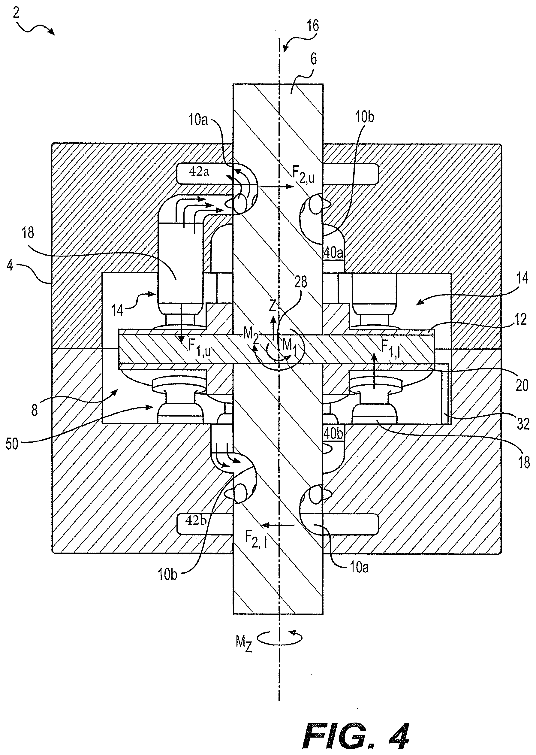
[0039] Another embodiment of the hydraulic pump is one designed with a drive key. This embodiment has a shaft-valve assembly. A valve is connected to a shaft via interaction between a drive key and a keyway. The connection between the valve and the shaft is maintained via any of a plurality of types of fasteners. The interaction is configured to provide at least one degree of freedom for the valve relative to the shaft. The degree (or degrees of freedom, if there is more than one degree of freedom) is in a linear direction that is configured perpendicular to an axis of rotation of the shaft. A swash plate is connected to the shaft. The swash plate rotates with the shaft and is configured to tilt about an axis perpendicular to the axis of the shaft via a means for tilting the swash plate.
[0040] The rotary valve is an elongated cylinder having a height that is preferably larger than the rotary valve's diameter. High pressure cross passages are juxtaposed in a side surface of the rotary valve. A low pressure transition zone is in the side surface of the rotary valve and is in contact with and extends a predetermined distance from the high pressure passages.
[0041] A is integral with a planar end of the rotary valve. A surface area of the hydrodynamic thrust bearing discharge thrust cavity is equal to about one half of the total area of end surfaces of the plurality of pistons.
[0042] A plurality of slipper assemblies is fluidly coupled to the swash plate. The slipper assemblies each include a slipper ball, a slipper neck and a slipper shoe. A hold-down plate maintains a fluid coupling between the slipper assemblies and the swash plate. The hold-down plate comprises a plurality of recesses each configured to engage a respective slipper assembly. The hold-down plate is prevented from rotating about the shaft.
[0043] Another embodiment is a segregated rotary valve/shaft embodiment. The rotary valve of the segregated embodiment is a rotating barrel valve. One of the advantages of this embodiment is the elimination of cantilevered forces by using a valve that emulates a barrel as opposed to a valve that is more disk-shaped. This is because a disk is susceptible to cantilever forces. This embodiment includes a shaft having a swash plate. The shaft and the swash plate rotate within a housing. A plurality of pistons oscillate in response to rotation of the shaft and the swash plate. The rotary valve is coaxial with the shaft and is fixedly attached at a planar end of the rotary valve to the shaft. The rotary valve is configured to rotate about an axis common to the shaft.
[0044] A beneficial feature of this embodiment is that an inlet port is centered along a main axis of the pump. One advantage to this configuration is that the number of turns of the inlet passageway within the rotary valve can be reduced. Thus, the possibility of cavitation is reduced. This embodiment includes a shaft and a rotary valve within a pump housing. The rotary valve is coaxial with the shaft and is connected to the shaft. A passageway is connected to the inlet port and has a path of travel with bends or turns of no less than ninety degrees. At least one high pressure passage is located in the rotary valve.
[0045] The pump housing has an integrated manifold and a plurality of cylinders. Cylinder bores are fluidly connected to the rotary valve high pressure passages. The bores alternately fluidly connect with the pump inlet and passageway and pump outlet upon rotation of the rotary valve.
[0046] This embodiment includes a manifold housing that has a plurality of piston bores. A rotary valve is rotatably housed within the manifold housing and includes an inlet orifice and an inlet passage that are serially and fluidly connected to the cylinder bores. The inlet passage has an axis through the rotary valve. The inlet passage has a maximum bend angle of about ninety degrees to avoid excessive fluid separation, thus increased fluid velocity through the passage.
[0047] The swash plate at least partially governs the flow rate through the inlet and the flow rate is further governed by rotational speed of the shaft. The rotary valve includes a plurality of high pressure cross passages juxtaposed in a side surface of the rotary valve. High pressure passages are fluidly connected to the high pressure cross passages and extend a predetermined distance from the high pressure cross passages. The planar end of the rotary valve provides for the presence of a discharge thrust cavity that is configured to balance axial forces on the pump.
[0048] A connection between the rotary valve and a drive element (shaft) can be via a rotary valve keyway and one or more c-clips. The advantage to this construction is that planar thrust loads are carried by the interface between the keyway, c-clips and the shaft and the interface provides a means for transmitting torque from the drive element to the rotary valve. The connection between the keyway of the rotary valve and the key of the shaft transfers torque from the shaft to the rotary valve.
[0049] The connection between the shaft and the rotary valve is locked by at least one and preferably by a pair of c-clips that are coaxial with the shaft. They engage a recess in the shaft and a corresponding recess in the rotary valve. The keyway can have at least one degree of freedom in the planar surface of the rotary valve
[0050] The rotary valve has components integrated in the surface of the rotary valve that are configured to balance the forces acting on the rotary valve. These components can also be configured to help balance the moments about the entire pump. At a minimum, the components are configured to balance rotational and axial forces within the pump.
[0051] The segregated shaft-valve pump (and the integrated shaft valve pump) can include pre-compression and decompression notches within the surface of the rotary valve. The advantage to this is the reduction of pump noise. Pump noise results from, among other things, fast changes of fluid pressure.
[0052] This embodiment of the pump includes a manifold that has a main bore and a rotary valve within the manifold-housing. The rotary valve includes a high pressure outlet and low pressure external surfaces. The rotary valve has an axis of rotation along a centerline of the main bore. At least one pre-compression notch is fluidly connected to an entry side of the high pressure outlet.
[0053] The rotary valve also includes an inlet in one of its planar surfaces. The inlet is centered about the rotary valve's axis of rotation. The rotary valve also includes cross passages in its curved side surfaces. The forces acting on the rotary valve due to high pressure fluid flow are balanced by the cross passages. At least one high pressure zone and at least one low pressure zone are provided by the cross passages. The high pressure zones and low pressure zones are configured about the rotary valve to eliminate moment forces on the rotary valve, placement of the zones being determined experimentally or by an equation in which all moments and forces on the valve are balanced.
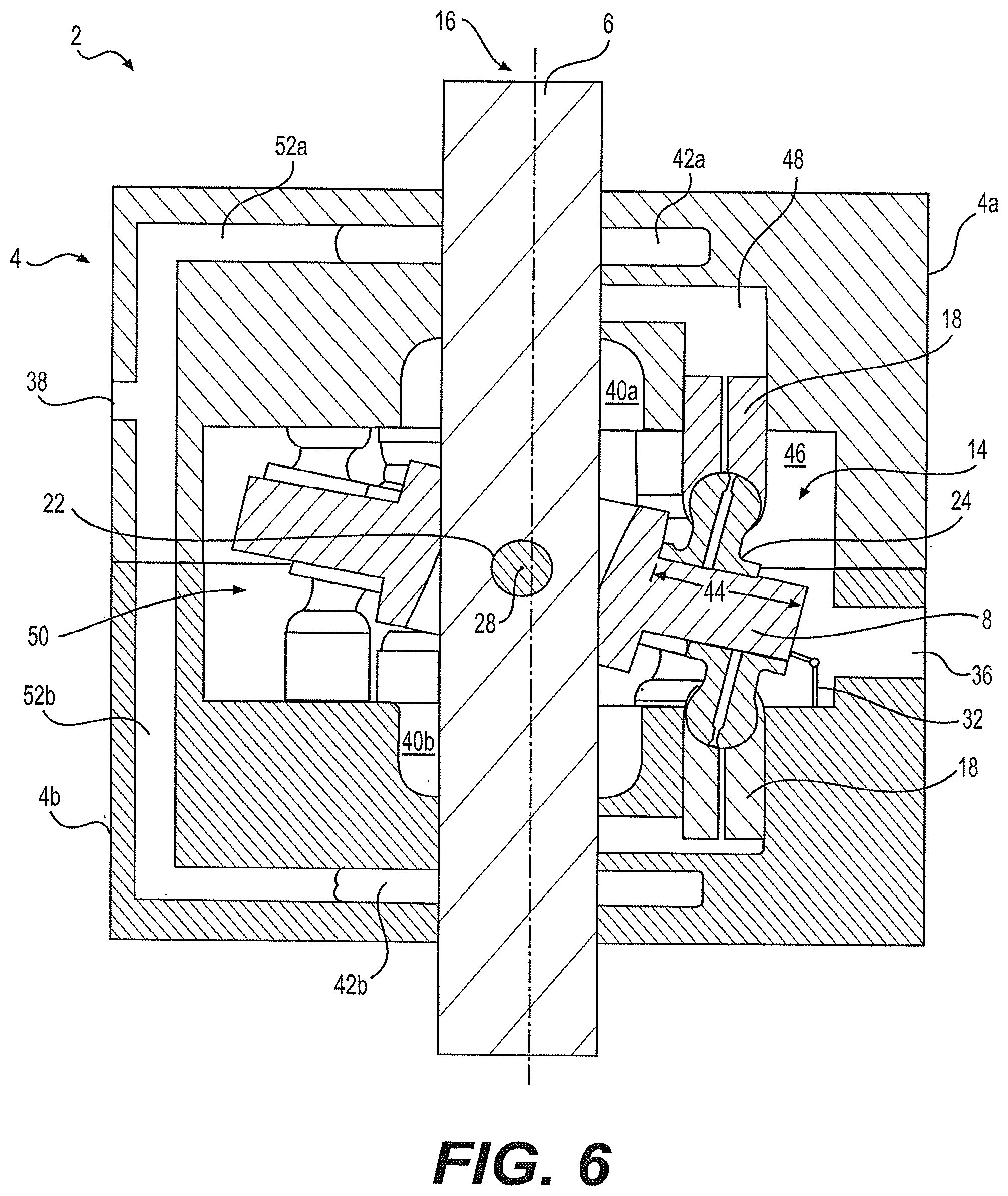
[0054] An advantage to the one piece cylinder block described above is that forces acting on seams within multiple part housings of prior art cylinder blocks are eliminated. The cylinder block contains a plurality of cylinder bores. A piston is slidingly positioned within each cylinder bore. The cylinder block is monolithic and the cylinder bores are integral with the cylinder block.
[0055] A hydraulic slipper assembly fluid supply channel is present through the entire length of the slipper assembly. Also, each of the plurality of pistons has a piston fluid supply channel that is fluidly coupled to the slipper assembly fluid supply channel and further fluidly coupled to the piston bore.
[0056] The disclosed subject matter employs a fluid bearing that allows relative motion between the pump's valve/shaft/swashplate and the cylinder block/manifold/housing. This configuration reduces the loads on all bearings within the device, which in turn reduces the parasitic bearing losses during operation.
[0057] The reduction of bearing loads is a function of the balance between the fluid forces and the structural response to those loads. Fluid forces occur in the pump when mechanical energy is transferred from the drive motor to the fluid as pressure and/or energy is transferred from the fluid into mechanical force or work into a load. By design there is a balance between the piston axial force, which is created by the reaction of the fluid pressure resisting the motion of the piston, and a second force which is the reactive force generated by the high pressure fluid acting on a planar surface of the valve/shaft (said planar surface, having a normal axial component). The net force (i.e. the difference in magnitude of the aforementioned first and second forces) varies continually during the operation of the device. The time varying imbalance of these forces requires the structure of the device to support the net residual forces and moments.
[0058] Non-rotating cylinder block technology advantages include lower mass and smaller device diameter, which affords lower rotational mass and thus inertia, which improves overall efficiencies when operating in non-steady-state conditions. Also, the cylinder block can be used as the device housing, thus obviating the need for the addition of a separate component, namely the housing as a structural member of the device.
[0059] The present pump uses the working fluid and the inevitable leakage from the working fluid (i.e. the fluid being displaced at high-pressure, that would otherwise have leaked between the various components within the pump only to be drained to a tank/reservoir, thus representing a 100% parasitic loss) to balance the aforementioned internal forces and/or moments on the rotating members (i.e. the shaft, swash plate, and valve; as well as, the mechanisms used to couple and/or control them). The present pump device minimizes the use of a predetermined (by design) controlled leakage of the working fluid to balance the internal forces on mechanical components as generated by the working fluid while it is displaced at high-pressure in a manner that does not require additional parasitic porting of said working fluid to develop the load resistant bearing (i.e. to support a hydrostatic bearing). This has the effect of improving the overall efficiency of the device. Thus, the present pump does not require the use of active element bearing (i.e. roller element type bearing). Typical axial piston devices, for the applied loads and rotational speeds, require large bearings in terms of diameter, weight and cost.
[0060] Embodiments of the disclosed pump have a valve geometry that is cylindrical, having a curved sealing/bearing surface. Conventional technology uses the valve plate as a planar bearing (i.e. two flat sealing surfaces separated by the working fluid acting as a fluid film). The advantage of the cylindrical shape is that, when operating under off-axis loaded conditions (i.e. eccentric position of cylinder relative to the bore), the clearance between the cylinder and its bore creates a variable gap size. This in turn creates a wedge like effect of the working fluid during rotation. This phenomenon, which is known as the wedge effect (see FIG. 3), produces a non-uniform pressure distribution within the load region which performs two functions. First and foremost, it provides a reaction force, equal to and opposite the applied load. Second, the wedge effect works to pull new fluid into the loaded region as the cylinder (or shaft) rotates, which replenishes the fluid lost due to pressure differential between the loaded region and the rest of the fluid cavity.
[0061] The disclosed pump combines the valve and journal bearing mechanisms into one component. The axial leakage flow from discharge to suction (across the bearing land) provides a means of heat transfer and thereby eliminates the need to port pressurized fluid (lubricant) through a dedicated port to the center of the journal land area.
BRIEF DESCRIPTION OF THE DRAWINGS
[0062] FIG. 1 shows a conventional pump having a non-rotating cylinder block;
[0063] FIG. 2 shows a conventional pump having a rotating cylinder block;
[0064] FIG. 3 shows a rotary valve experiencing a wedge effect;
[0065] FIG. 4 shows a first embodiment of a self-balancing hydraulic pump;
[0066] FIG. 5 shows a plurality of pistons in the inventive hydraulic pump arranged arcuately;
[0067] FIG. 6 shows the first embodiment of the hydraulic pump with a tilted swash plate;
[0068] FIG. 7 shows a second embodiment of the hydraulic pump;
[0069] FIG. 8 shows a third embodiment of the hydraulic pump;
[0070] FIG. 9 is a cross-sectional view of the hydraulic pump shown in FIG. 5;
[0071] FIG. 10 is a further cross-sectional view of the hydraulic pump shown in FIG. 5;
[0072] FIGS. 11A-11B are detailed views of a rotary valve of the hydraulic pump of FIG. 5;
[0073] FIG. 12 is a detailed view of a swash plate;
[0074] FIG. 13 is a detailed view of a slipper assembly;
[0075] FIG. 14 is a view of a two-piece rotary valve;
[0076] FIG. 15 is a rotary valve showing significant wear;
[0077] FIG. 16 is a cross sectional view of a pump showing a first version of a rotary valve;
[0078] FIG. 17A is a first view of a sealing section of the rotary valve shown in FIG. 16;
[0079] FIG. 17B is a second view of the sealing section shown in FIG. 17A;
[0080] FIG. 17C is a cross sectional view of the sealing section of FIG. 17A showing pressure drop across surfaces of the sealing section;
[0081] FIG. 17D is a first view of the sealing section of FIG. 17A attached to the rotary valve;
[0082] FIG. 17E is a second view of the sealing section of FIG. 17A attached to the rotary valve;
[0083] FIG. 18 is a first cross sectional view of the entire pump using the rotary valve of FIG. 16;
[0084] FIG. 19 is a second cross sectional view of the entire pump using the rotary valve of FIG. 16 with the rotary valve having been rotated ninety degrees from its position in FIG. 18;
[0085] FIG. 20 is a top view of the rotary valve and sealing section of FIG. 16 inside a valve bore;
[0086] FIG. 21 is a cross sectional view of a pump showing a second version of a rotary valve;
[0087] FIG. 22A is a first view of a sealing section attached to the rotary valve of FIG. 21;
[0088] FIG. 22B is a second view of a sealing section attached to the rotary valve of FIG. 21;
[0089] FIG. 23 is a cross sectional view of the sealing section of FIG. 21 showing pressure drop across surfaces of the sealing section;
[0090] FIG. 24 is a top view of the rotary valve and sealing section of FIG. 21 inside the valve bore;
[0091] FIG. 25 is a cross sectional view of a pump showing a third version of a rotary valve;
[0092] FIG. 26 is a cross sectional view of the rotary valve and shaft of the pump shown in FIG. 25;
[0093] FIG. 27 is an axial face seal embodiment and a radial face seal embodiment;
[0094] FIG. 28 is a partial view of an rotary face seal;
[0095] FIG. 29 is a perspective view of an axial face seal;
[0096] FIG. 30 shows a double sided pump having the radial face seal embodiment and rotary face seal embodiment of FIG. 27;
[0097] FIG. 31 is a cross sectional view of the valve and radial face seal and shows a pressure gradient at the valve's radial face seal; and
[0098] FIG. 32 is a cross-sectional view showing an O-ring relative to a passage in the valve.
DETAILED DESCRIPTION OF THE INVENTION
[0099] FIG. 4 shows a hydraulic pump 2. The pump 2 includes a housing 4. A shaft-valve 6 extends along an entire length of the housing 4. The shaft-valve 6 allows for balancing of forces and/or moments within the pump 2. As a result of the force and/or moment balancing, the necessity for mechanical bearings in the pump is reduced. Therefore, construction and capability of the pump 2 are not limited by the capabilities of any rolling element bearings during operation as roller element bearings are not necessary in the pump 2.
[0100] This embodiment of the pump 2 has a plurality of passages 10a and 10b in the shaft-valve 6. Fluid flow throughout the pump 2 and rotation of a swash plate 8 creates a force and/or moment on the shaft-valve 6. Fluid flow is a result of the rotating swash plate. Pistons cause the fluid flow via their reciprocation that results from engagement with the rotating swash plate. Thus, the rotating swash plate (and fluid flow) creates the forces on the pump. The plurality of passages 10a and 10b are configured in the shaft-valve 6 such that the forces and/or moments on the shaft-valve 6 are balanced.
[0101] A rotary valve that is separate from the shaft is beneficial in certain circumstances and is discussed below in detail. In the present embodiment, however, the passages 10a and 10b are integral with the shaft-valve 6 and eliminate any need for a separate rotary valve as the functions of a rotary valve and the shaft are performed by a single component--the shaft-valve 6. A conventional non-rotating cylinder block pump that does not have a rotary valve as disclosed herein is shown in FIG. 1.
[0102] The swash plate 8 is connected to the shaft-valve 6 and is preferably configured to tilt about an axis 28, perpendicular to the axis of the shaft-valve 6. The swash plate 8 has a first side 12 coupled to a first plurality of slipper assemblies 14. Contact between the slipper assemblies 14 and the swash plate 8 is shown in FIG. 5. The shaft-valve 6 is self-centering within the housing 4 about its own physical axis 16, i.e., the shaft-valve's 6 axis of rotation is aligned as much as possible with the shaft-valve's axis of symmetry. The swash plate 8 is a double sided swash plate. The swash plate 8 is disk shaped and symmetrical about a plane through the middle of the disk. The first side 12 is preferably a planar surface. The swash plate 8 has a second side 20, which is also a preferably planar surface. The first side 12 and the second side 20 of the swash plate 8 oppose each other. A second plurality of slipper assemblies 50 is coupled to the second side 20 of the swash plate 8.
[0103] The use of wedge shaped swash plates in double sided pumps dominated the prior art; however, in the present pump 2, the first side 12 of the swash plate and the second side of the swash plate 20 are as close to parallel to each other as possible. It is not necessary that the first side 12 and the second side 20 be absolutely parallel to each other. However, the closer to parallel the first side 12 and the second side 20 are, the closer to fully balanced the forces and/or moments on the shaft-valve 6 will be.
[0104] Each of the slipper assemblies 14 includes a piston 18. The housing 4 acts as a cylinder block for each piston 18. In the pump 2, the housing 4 is non-rotating and each piston 18 remains circumferentially stationary while the shaft-valve 6 and swash plate 8 rotate. This is in contrast to prior art pumps in which the cylinder block rotates.
[0105] With reference to FIG. 6, the first plurality of slipper assemblies 14 is coupled to the first side 12 of the swash plate 8 and a second plurality of slipper assemblies 50 is coupled to the second side 20. At the end of each slipper assembly 14 is a slipper shoe 24. The slipper shoe 24 can slide a distance 44 along a surface of the swash plate 8. Coupling between the slipper shoes 24 and the sides 12 and 20 of the swash plate 8 is via a fluid bearing. Thus, the slipper shoes 24 slide freely along the surface of the swash plate 8.
[0106] A pin 22 anchors the swash plate 8 at a fixed distance relative to the end of the shaft-valve 6. Regardless of the means used to anchor the swash plate 8, the swash plate 8 is configured to be adjustable about the axis 28 that is askew or perpendicular to the axis of the shaft-valve 6. Increasing or decreasing a swash angle of the swash plate 8 adjusts the volumetric displacement of the hydraulic pump 2 i.e., fluid volume displacement per shaft revolution. The greater the swash angle of the swash plate 8, the higher the volumetric displacement per revolution of the pump 2. As the swash angle of the swash plate 8 is increased, the stroke of each of the pistons 18 in the slipper assemblies 14 and 50 is increased. Thus, the piston bore 48 that houses each piston 18 can accommodate more fluid to thereby increase the volumetric displacement.
[0107] To actuate the pistons 18, the shaft-valve 6 rotates on its axis 16. Rotation of the shaft-valve 6 causes the swash plate 8 to rotate about axis 16. When the swash plate 8 is tilted, interaction of the swash plate 8 with the slipper assemblies 14 and 50 causes the pistons 18 to reciprocate along each individual axis of each piston 18. Interaction between the each slipper assembly 14 and 50 and the swash plate 8 is enhanced by the presence of a fluid bearing between the swash plate 8 and slipper assemblies 14 and 50. The fluid bearing is provided by high pressure fluid that is fed through the center of the piston and slipper.
[0108] The swash plate 8 is tiltable about an axis 28 of the pin 22. Operatively connected to the swash plate 8 is a means 32 for tilting the swash plate 8 (i.e. angular position), relative to the shaft-valve's 6 rotational axis 16. The means 32 for tilting the swash plate 8 can be any of a hydraulic means such as a hydraulic jack or cylinder, a mechanical dog-bone assembly responsive to mechanical input, an electric means, a gearing system, or any combination thereof. The shaft-valve 6 is capable of unintended but sometimes unavoidable eccentric rotation (and centric rotation) during operation of the pump 2. Hence, it is advantageous to have the shaft-valve 6 be self-centering. As shown in FIG. 5, the plurality of passages 10a and 10b receive, direct and exhaust fluid into, around and from the shaft-valve 6 throughout the pump 2. Each of the plurality of pistons 18 is arcuately positioned coaxially with the shaft-valve 6. The plurality of pistons 18 are grouped in two sets and are on opposite ends of the housing 4 and engage with sides 12 and 20 of the swash plate 8, respectively.
[0109] The housing 4 has the at least one inlet passage 36 for receiving fluid in the pump and at least one outlet passage 38 for expelling fluid from the pump 2. The passages 10a and 10b on each end of the shaft are generally one-hundred and eighty degrees apart.
[0110] As can be seen in FIG. 6, fluid enters the housing 4 at inlet passage 36 and proceeds to low pressure cavity 46. Fluid enters a plurality of piston bores 48 via low pressure ports 40a and 40b and low pressure passages 10b (see FIG. 4). As the shaft-valve 6 rotates, low pressure passages 10b are continuously aligned with low pressure ports 40a and 40b. High pressure passages 10a are continuously aligned with high pressure ports 42a and 42b. High pressure ports 42a and 42b connect with outlet passage 38 via lines 52a and 52b.
[0111] The forces acting on the shaft-valve 6 (primarily caused by the moment generated by high pressure fluid forces on the pistons) are balanced via the geometry and location of the passages 10a and 10b. With further reference to FIG. 4, when passage 10a is engaged with high pressure port 42a, passage 10b, which dynamically opposes passage 10a, i.e., which balances forces on the pump, engages with low pressure port 40b. This is because the actions of the slipper assemblies are in opposition to each other due to their generally opposing positions on the swash plate 8 (i.e., when the swash plate 8 is tilted and rotating, one slipper assembly is sliding out of its bore thereby creating a vacuum, while an opposing slipper assembly is sliding into its bore helping to create high pressure on the fluid situated inside the bore). The effect is for the forces on the pump 2 that are caused by fluid flow within the pump 2 balance the forces of the slipper assemblies 14 and 50 on the swash plate 8 on.
[0112] The sides 12 and 20 of the swash plate 8 apply pressure on the slipper assemblies 14 on the high pressure half of the swash plate 8 due to the tilt of the swash plate 8, relative to the shaft-valve 6 (known as the swash angle). Each slipper shoe 24 of each slipper assembly 14 and 50 is then forced to apply pressure on each respective piston 18, which communicates with the fluid inside the piston bore 48. As shown in FIG. 4, this process creates four different forces/moments (F.sub.1,u, F.sub.1,l, M.sub.1, M.sub.2). An axial load (F.sub.1) is carried by the swash plate 8. There are two components to the axial load (F1u and F1l) that are equal and opposite. There are trade-offs in back to back piston alignment. Full balance of axial loads can be achieved with zero indexing (i.e. misalignment), whereas indexed pistons results in non-zero net axial load. However, the indexing of back to back pistons provides an adequate balance of axial loads, the advantage of indexing is that the flow ripple (i.e. vibration, noise, pressure/flow pulsation, etc.) can be greatly reduced (i.e. nearly half the amplitude of zero indexing).
[0113] A radial load (F.sub.2) is carried by the shaft-valve 6. There are two components to the radial load (F.sub.2,u and F.sub.2,l). These components F.sub.2,u and F.sub.2,l are equal and opposite to each other, thereby resulting in zero net radial loads. A moment (M.sub.1) is carried by the swash plate 8, which is transferred through the pivot pin 22 to the shaft-valve 6. An equal and opposite moment (M.sub.2) is carried by the shaft-valve 6 by means of a pressure differential between the high pressure passages 10a and the low pressure passages 10b (M2 is created by F2,u & F2,l). Another force/moment is the moment (M.sub.z) about the axis of rotation, which is reacted by the input torque required to drive the shaft-valve 6. Thus, the shaft-valve 6 and all other rotating members are balanced. The balance of the rotating members is independent of the swash angle.
[0114] The housing 4 shown in FIG. 4 and FIG. 6 is a two part housing including parts 4a and 4b. However, the housing can be monolithic or it can be of many components. If the housing 4 is of many components, it is beneficial to provide a static seal, e.g., o-ring or gasket between the components. The components can be held together via a flange or socket type connection. With the two component configuration, a first stationary housing/cylinder block 4a encompasses the first plurality of pistons and a second stationary housing/cylinder block 4b encompasses the second plurality of pistons.
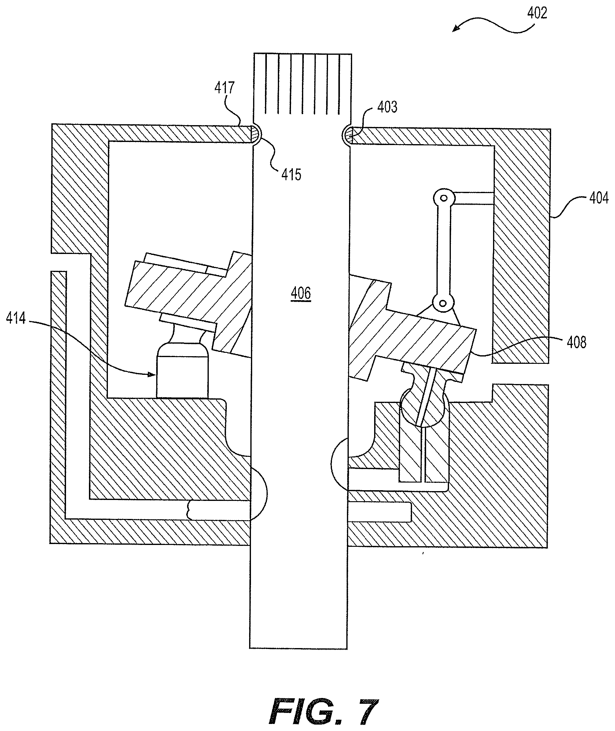
[0115] As shown in FIG. 4 and FIG. 6, the components that are coupled to the first side 12 of the swash plate 8 are substantially symmetric about the swash plate 8 with respect to the components that are coupled to the second side 20 of the swash plate 8. However, the pump disclosed herein is not limited to the double sided configuration shown in FIG. 4 and FIG. 6. As shown in FIG. 7, a single sided pump 402 embodiment is contemplated. In the single sided pump 402, the swash plate 408 is configured at one axial end of the pump 402. In this case, fluid bearings 403 are more necessary as opposing sets of slipper assemblies are not present in this embodiment. Rather, a single set of slipper assemblies 414 are used. Therefore, moments and forces that are created by rotation of the swash plate and fluid forces can be zeroed out. To compensate for axial forces, a notch 415 or similar relief can be added to the shaft-valve 406 and engage with edge 417 of housing 404.
[0116] It is conceivable that at least one additional pump (not shown) is included in the single housing and configured substantially similar to the first and/or second pumps. The additional pumps would be situated parallel to the first and second pumps within the housing. Thus, a plurality of pumps is contained within a single housing such that two or more shaft-valves are within the housing and in parallel with each other. A parallel configuration is not necessary. Operation of each pump within the housing can be completely independent of operation of another pump within the housing.
[0117] A further embodiment of the present hydraulic pump is one in which the shaft-valve 6 is designed for motion about at least three degrees of freedom and as many as four degrees of freedom. There are two linear degrees of freedom and at least one rotatable degree of freedom about an axis perpendicular to the linear degree of freedom.
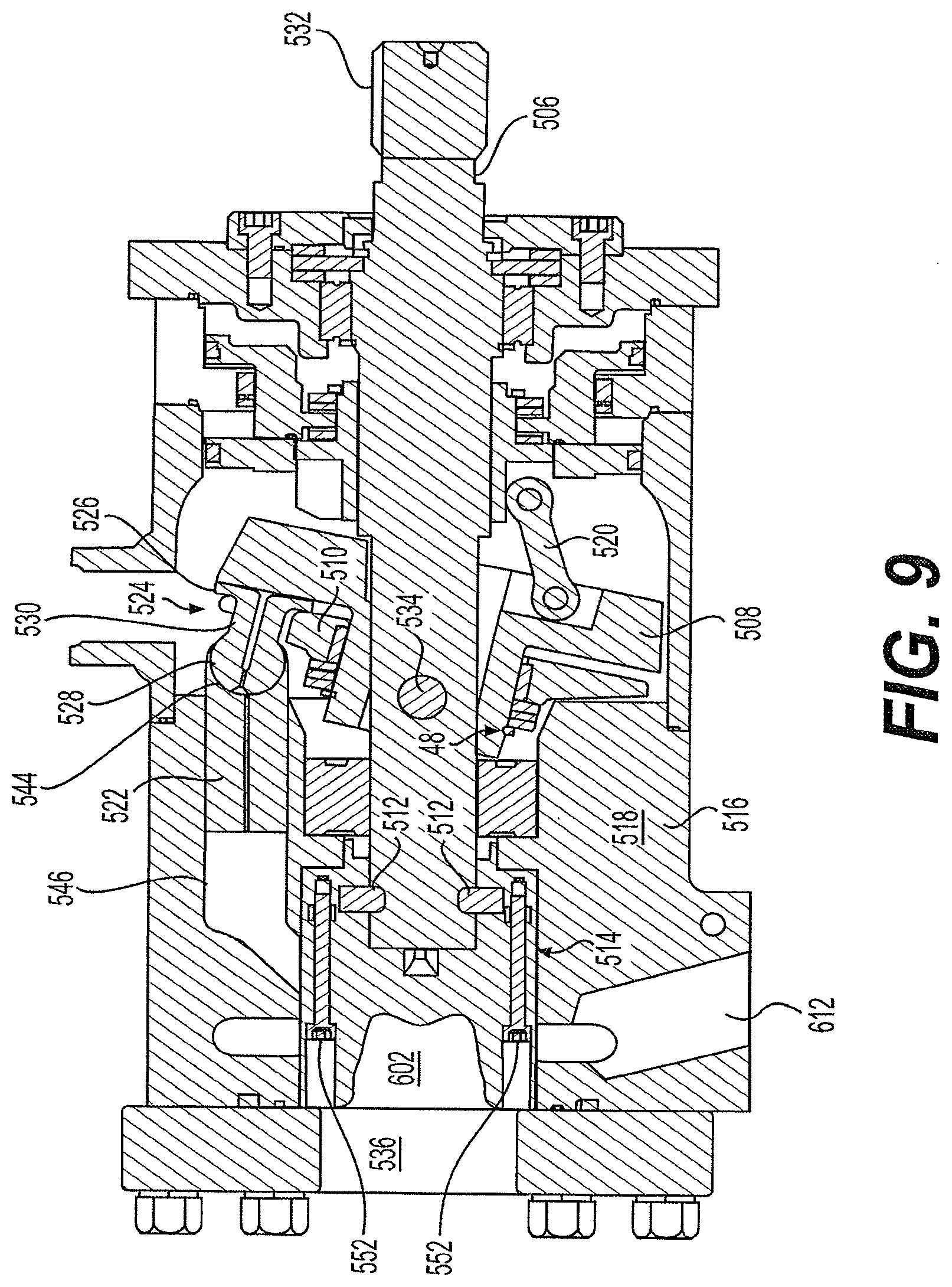
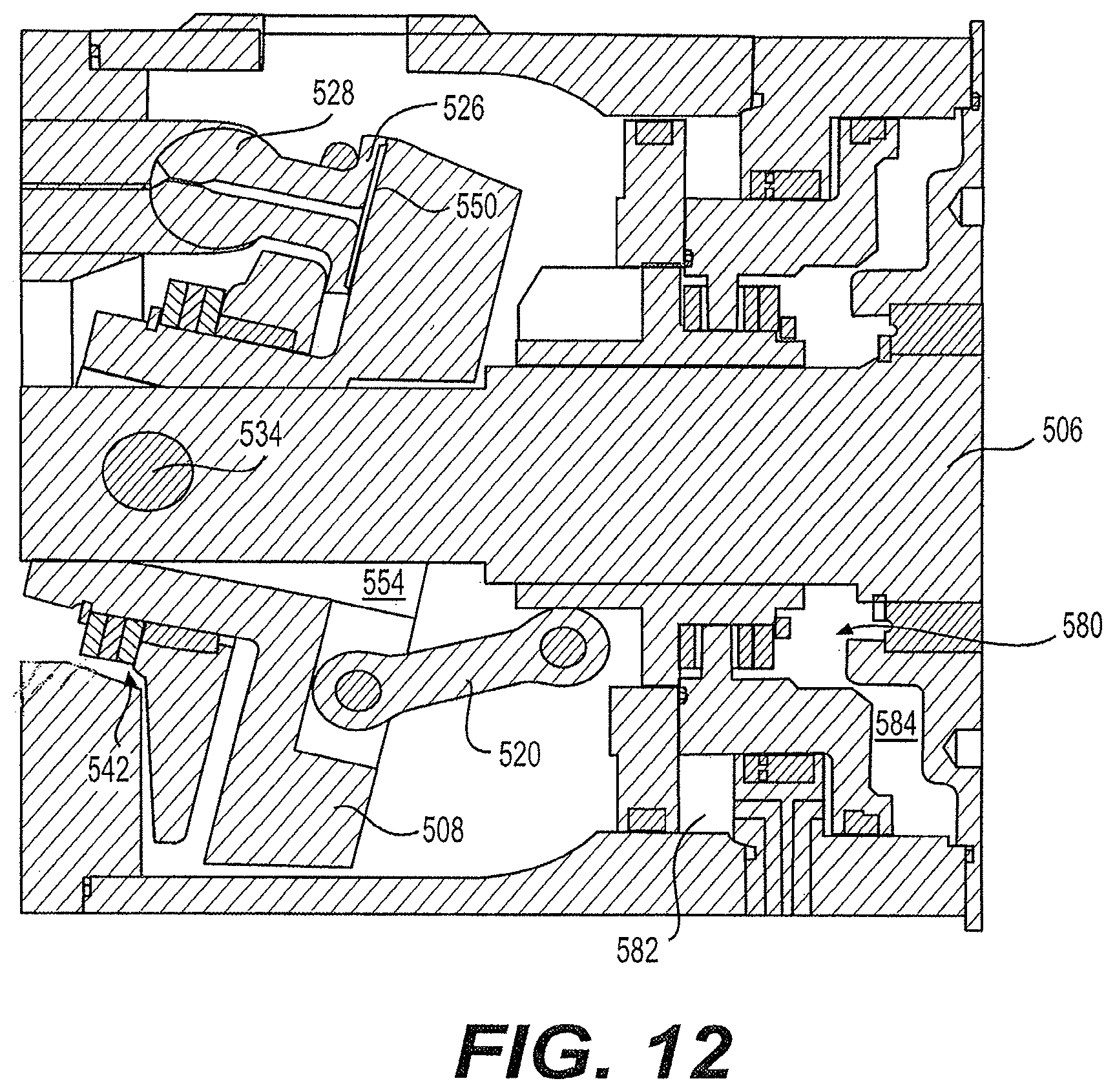
[0118] An additional embodiment of an inventive pump 502 is shown in FIG. 8-FIG. 12 and is one in which a shaft and a valve are not integrated as in the previous embodiments. With particular reference to FIG. 8 and FIG. 9, components of the pump 502 include a pump housing 504 (shown in FIG. 8), which houses a shaft 506, a swash plate 508, a hold down plate 510, one or more c-clips 512, a rotary valve 514, a cylinder block 516, a manifold 518, a swash plate control link 520 for setting an angle of the swash plate 508, a plurality of pistons 522, and a plurality of slipper assemblies 524. Each of the slipper assemblies 524 contains a slipper shoe 526, a slipper ball 528 and a slipper neck 530, each slipper neck 530 connects a slipper shoe 526 to a respective slipper ball 528.
[0119] The shaft 506 is positioned along a center axis of the pump housing 504. One end of the shaft 506 extends outside of the pump housing 504 and includes a spline 532. The spline 532 is toothed for attachment to a gear of a motor, crank, flywheel or some other motion transferring mechanism. The shaft 506 is held in place by multiple bearings at each end of the pump 502.
[0120] The connection between the valve 514 and the shaft 506 is configured to limit transfer of force, from the shaft to the valve, to a torque about an axis of rotation of the shaft and a thrust load along the axis of rotation. The valve 514 is balanced within the cylinder block 516 by controlled leakage rates as a function of force and/or moment on the valve 514.
[0121] The hydraulic pump 502 intakes fluid through a non-rotating cylinder block and passes it through the rotary valve 514. The rotary valve 514 is in constant communication with an inlet port 536 and an discharge port 612 as well as a plurality of piston bores 546 within the cylinder block 516.
[0122] In an embodiment, and with reference to FIG. 10 and FIG. 11A-11B, low pressure fluid enters the pump through an inlet port 536 into the inlet cavity 602. This fluid is passed on to the plurality of piston bores 546 by way of the valve inlet passage 614. Each piston 522 in communication with the valve inlet passage 614 is being forced out of the piston bore 546. When a piston bore 546 is closed off from the valve inlet passage 614, the low pressure fluid becomes trapped. As the valve 514 continues to rotate, the piston 522 is forced into the piston bore 546, thereby compressing the fluid inside the bore 546. At this time, the piston bore 546 begins to open up to a valve discharge passage 616. The valve discharge passage 616 allows for the high pressure fluid from the piston bore 546 to be passed on to a discharge cavity 618 where it then exits the pump through a discharge port 612 at an end of outlet cavity 612. The force required to move the pistons is provided by an input torque into the shaft 506 (see FIG. 9). This torque is transferred to the pivot pin 534 (see FIG. 9), where it is then transferred to the swash plate 508.
[0123] At an opposite end of the shaft 506 from the spline 532, the rotary valve 514 is attached and held in place via the c-clips 512. Whenever the shaft 506 rotates, the rotary valve 514 rotates at the same rotational velocity. Similarly, between each end of the shaft 506, a swash plate 508 is connected to the shaft 506 via a pin 534. Whenever the shaft 506 rotates, the swash plate 508 rotates at the same rotational velocity as the shaft 506. The shaft 506 functions as a rotational motion transmission component in that it accepts rotational motion from an external motor to ultimately cause the rotary valve 514 and swash plate 508 to rotate thereby creating a pumping force.
[0124] Alternatively, the shaft 506 receives a rotational motion from the swash plate from fluid passing through the rotary valve which are translated into rotational motion to turn the spline 532 (i.e., to cause the pump to act in reverse as a motor). To reverse flow (alternatively referred to hereinafter as "going over center"), additional cross passages must be added on the opposite side of the valve from where they are currently. The reason for adding additional cross passages is because high pressure cross-passages become low pressure and vice versa.
[0125] With reference to FIG. 12, the swash plate 508 is attached to the shaft 506 via the pin 534. The pin 534 in the shaft 506 allows the swash plate 508 to tilt, thereby altering the axis of the swash plate 508 relative to the axis of the shaft 506. A hollow stem 554 extends from a bottom surface of the swash plate 508. The pin 534, which engages with the shaft 506 is positioned within the stem 554. Other than where the stem 554 extends from the swash plate 508, the bottom surface of the swash plate 508 is flat. Such a flat surface of the swash plate 508 allows for a sliding interaction between the flat bottom of the swash plate 508 and the slipper shoes 526, which are explained in more detail later.
[0126] The pin 534 facilitates rotation of the swash plate 508 about the axis of the shaft 506. The pin 534 provides for torque and thrust loads to be transferred between the swash plate 508 and the shaft 506. The advantage of the pin 534 affords a one-piece swash plate, which affords structural stability due to the forces acting on opposite sides of the swash plate 508.
[0127] In previous pumps, a rotating cylinder block was used. As such, it was necessary to have bolts holding the housing to the block. An axial pump's housing was a combination of two components where the pump was held together by all of the bolts. It was necessary to contain the separation force of multiple piston areas whereas with the present design, it is only necessary to consider the weight of the components and the forces that the bearings are imposing (due to the one piece housing). This is advantageous in that the bolts have a much longer life because tension forces are not acting on the bolts. Also, seals would be necessary to maintain the hydraulic fluid within the junction between the block and the housing.
[0128] Radial loads on the pump are limited by limiting the tilt of the swash plate. There is less of side load or moment (less of a radial load) with smaller tilt angles. Thus, the importance of a radial bearing is reduced and a lighter duty bearing can be used. Further, the present pump allows for a reduced stroke. The pistons are shorter but wider than conventional pistons. Therefore, the present pump can displace the same amount of volume as conventional pumps via a reduced swash plate tilt angle. The cylinder block is integral with the pump housing. Reciprocating pumps with fixed cylinder blocks have structural advantages. By removing rotation of the cylinder block, centripetal forces are eliminated and a structural unit of reduced size and mass is possible.
[0129] Also, as there is a shorter tilt angle of the swash plate (no greater than about twelve degrees is necessary for operation of this pump), there can be an increased bore/piston diameter without a decrease in volume flow rate. Increased diameter, and decreased swash plate tilt angle result in a majority of the load being axial rather than radial. This results in less friction and wear on pistons, which in turn produces higher mechanical efficiency. A series of bearings 542 are meant to accommodate a moment load about an axis perpendicular to the pin 534. The bearings 542 are above and below a center point of the pivot pin 534 to balance out the high pressure and low pressure sides of the swash plate 508.
[0130] The swash plate's axis of tilt and the center of the slipper ball 528 are in line along the same plane, which is parallel to the sliding face of the swash plate 508. This configuration limits the size of the path travelled by the slipper shoe 526 along the sliding face of the swash plate 508.
[0131] A lemniscate resembles the shape of an infinity sign; it may also be described as a Figure-8. This shape represents the path of which the slipper shoe 526 travels about the undersurface of the rotating swash plate 508 during displacement. In addition to the lemniscate path, the slipper shoe 526 also travels three hundred and sixty degrees about the swash plate 508 (more precisely, the swash plate rotates 360.degree. about the non-rotating slipper shoes 526). Effectively, the slipper shoe 526 moves radially, inwards and outwards, as the swash plate 508 is rotated. During this rotation, the fluid within a slipper pressure pocket 550 (shown in FIGS. 12 and 13) is constantly being sheared.
[0132] Each slipper shoe's slipper shoe pressure pocket 550 is centered on the flat surface of shoe that contacts the flat undersurface of the swash plate 508. Each respective slipper shoe pressure pocket 550 is connected to a fluid supply to assure that fluid pressure present at the shoe/swash plate interface is proportional at all times with fluid pressure at the head of each piston 522.
[0133] With reference to FIG. 13, the slipper ball 528 engages with the piston 522 in slipper ball receiving portion 544. Because the slipper ball 528 can actually go into the piston's bore 546, one can limit the length of the piston 522, which in turn limits the exposed surface (length) of the piston 522 at full extension, which in turn reduces unwanted moment loads. During operation of the pump 522, axial motion of the piston 522 is translated to the slipper ball 528. The slipper ball 528 also rotates about its center and therefore generates lateral motion and resulting forces. The lateral forces cause an unwanted moment about an axis orthogonal to the shaft's axis of rotation. To reduce this moment, lateral motion (and resulting forces) in the is reduced. One way to reduce lateral motion and forces is to reduce the stroke of the piston 522 as described elsewhere herein.
[0134] The swash plate 508 rotates with the shaft; but the slipper assembly 514 does not. There is a fluid film bearing 576 between swash plate 508 and the slipper shoe 526. The slipper shoe 526 maintains alignment with the non-rotating pistons 522 and bore 546 notwithstanding the constantly varying tilt of the slipper shoe 526. As such, the slipper shoe 526 moves in a lemniscate path within its slipper ball receiving recess 572. The path of the slipper shoe 526 around the underside of the swash plate 508 is elliptical (not circular). Further, only the slipper shoe and hold down plate nutates (i.e. oscillation of an axis or revolution of a tilted axis about a central axis).
[0135] The hold down plate 510 holds the slipper assembly 524 in place against the swash plate 508. The hold down plate 510 is kept in place on the swash plate 508 by the series of bearings 542 that fixedly engage the swash plate 508. To assemble the hold down plate 510 on the swash plate 508, the hold down plate 510 has a through hole in its center. The swash plate 508 slides through the center hole of the hold down plate 510 and the series of bearings 542 are slid on the swash plate 508.
[0136] The hold-down plate 510 is provided with a plurality of openings, each of which surrounds a neck 530 of a respective slipper assembly 524. A respective special washer 578 is fixed to integral with the slipper shoe 526. Each washer 578 maintains the shoe in contact, via the fluid bearing 576, with the flat undersurface of the swash plate 508 at all times. The hold down plate 510 is prevented from rotating independent of the slipper shoe 526 while at same time the hold down plate 510 does not restrict the movement of the slipper shoe 526. The hold down plate 510 holds slipper shoe 526 flush with the swash plate 508, maintaining pressure between slipper shoe 526 and the swash plate 508.
[0137] The angle of the swash plate 508 is adjusted by pumping fluid into one of two volumes 582 and 584. Fluid is pumped from an external source into the first volume 582 to raise a shift piston 580 or it is pumped into a second volume 584 to lower the shift piston 580. The shift piston 580 is hydraulically actuated up and down the shaft 506 to change the angle of the swash plate 508. Shift piston displacement is controlled externally. Hydraulic control is affected through an external hydraulic control mechanism (not shown). Displacement of the shift piston 580 results in swash angle displacement, which results in displacement of pistons 522, which produces fluid displacement.
[0138] With further reference to FIG. 13, hydraulic fluid is allowed access to slipper shoe pressure pocket 550 via a through-hole 573 in the slipper ball 528. The hydraulic fluid acts as both a seal and a bearing for the interaction of the slipper shoe 526 with the flat surface of the swash plate 508. The neck 530 connects the slipper shoe 526 to the slipper ball 528. The slipper neck 530 has a through-hole 574, which is a continuation of the through-hole 573 of the slipper ball 528. Slipper ball fluid entry 572 is in constant communication with piston through-hole 571 to enable access to high pressure fluid pumped by piston 522. To this end, fluid entry 572 is preferably conical to account for the constant rotation of the slipper ball 528.
[0139] With reference to FIG. 14, an embodiment of the rotary valve 514 is a two piece assembly: thrust plate 600 and valve body 601 are held together by screws 552 (shown in FIG. 9), adhesives or any other suitable fastener. Together they act as one valve 514. Thrust plate 600 carries the thrust load created and carried through the shaft 506. The shaft 506 drives the rotary valve 514 through a torque component only. The shaft 506 and the rotary valve 514 are mated solely to affect a torque or rotational movement of the valve. The rotary valve 514 includes the inlet 602 (FIG. 9), an discharge passage 616 and balancing recesses 606a and 606b. The balancing recesses 606a and 606b are configured to receive hydraulic fluid such that, as the shaft 6 and the rotary valve 514 rotate and as the pistons 522 oscillate, the moments caused by the motion of these components is counterbalanced by the pressure within the balancing recesses 606a and 606b. A pre-compression notch 620 is provided on the leading edge of the discharge passage 616 directly on the curved surfaces of the rotary valve. This pre-compression notch 620 is provided to reduce damage to the valve resulting from a rapid increase in pressure at the discharge passage 616. The pre-compression notch provides control of the rate of pressure increase within individual pumping chambers that minimizes the resulting impact forces on the pistons. By minimizing the impact forces on the pistons, the attendant noise that results from the contact between the slipper shoe and swashplate and eventually radiated to the local environment is minimized.
[0140] The thrust plate 600 is located on an upper portion of the rotary valve 514 opposite the inlet passage 602. The surface area of the thrust plate 600 is equal to half of the total surface areas of the pistons (as half of the surface area will be under high pressure at any one time). A major obstacle for any axial piston pump is dealing with the large thrust loads, which are created by the continuously shifting high pressure force on the piston from the piston bore 546. Half of the pistons will have a high pressure flow while the other half will have a low pressure flow, depending on the position of the piston within the bore. Lubrication happens in high or low pressure. The load is transferred from the piston 522, to slipper shoe 526, to swash plate 508, to shaft pin 534, and finally to the shaft 506. The thrust plate 600 is used to counter act the thrust load, which otherwise would force the shaft 506 away from the cylinder block 516.
[0141] It is not necessary to place low pressure recesses on the rotary valve as the film strength along the surface of the rotary valve is enough to counter the smaller inlet pressure values. Further, adding additional cross passages would result in too much fluid loss.
[0142] As can be seen in FIGS. 11A and 11B, the recesses in the rotary valve 514 form one volume with the cylinder bores 546. Thus, the pressure is equal throughout that volume. The recesses 606a and 606b help to counteract the moment caused by pressure rotation around the plurality of pistons 522. The pistons 522 do not rotate around the axis of the shaft 506; however, the reciprocal motion of the pistons 522 within their respective bores 546 causes a moment about an axis perpendicular to the axis of the shaft 506. The recesses also allow for the inlet passage 536 to be centered along the axis of the rotary valve (and the axis of the pump). Due to the non-rotating pistons, centripetal forces are eliminated. The rotary valve 514 is therefore automatically self-centered with the use of cross porting hydrodynamic balance.
[0143] The recesses 606a and 606b of FIGS. 11A-11B represent areas of high pressure; whereas the inlet 602 represents low pressure. The inlet pressure is close to atmospheric conditions unless otherwise provided with pressure. The outlet pressure can reach 6000 psi and more. The two recesses 606a and 606b are split apart by the high pressure outlet passage 612. Recess 606a is larger than recess 606b to balance the moment about an axis perpendicular to the axis of rotation. The surface between the passages 606a and 606b is long enough to ensure a proper seal of the valve in its bore. The length of each of the passages 606a and 606b is based on fluid pressure. The following equation is used to determine a ratio of 606a to 606b:
[0144] Hydrodynamic thrust bearing 610 is a fluid filled volume between the thrust plate 600 and the manifold 518.
[0145] The projected areas of the high pressure outlet 612 and valve discharge passage 616 are equal in size; thereby balancing the lateral forces on the rotary valve 514 in the. Additionally; these areas are positioned on the y-axis in such a way that the sum of the moments about the center of mass is zero. The thrust bearing at the upper end of the pump can handle one piston worth of area at operating pressure.
[0146] The rotary valve's inlet flow is through the inlet passage 602 in the center of the valve along the valve's axis (and accordingly along the axis of the pump 502) and the rotary valve 514's outlet flow is ported around the periphery of the pump frame. The location of the outlet 612 has the additional benefit that it helps to cool the pump 502. The inlet passage 602 through the center of the rotary valve 514 allows for a more direct flow path to the piston bore 546. This also decreases the volume of the suction cavity as it affords a more direct flow path and lower surface area, which also reduces fluid friction and thereby reducing parasitic losses.
[0147] The present pump 502 combines a piston housing and a discharge cavity (manifold) in one unit (component). By combining high pressure forces into one housing, forces of separation that would normally present in prior art pumps are eliminated. Without the balancing effect of rotary valve 514, the valve would tip or tilt, and potentially break the fluid barrier, and potentially seize the rotating parts of the pump 502. With the forces, the valve will seek its own center within its bore.
[0148] The following embodiments are intended to avoid wear 698 on a rotary valve as show in FIG. 15. Such wear is typically caused by eccentric rotation and tipping of the valve within the pump's valve bore.
[0149] With specific reference to FIG. 16, a first disclosed embodiment is a pump 702 that includes a housing 704 and an integrated manifold 706. A rotary valve 708 is encompassed by the manifold 706. The rotary valve 708 includes a shaft 710, a ported section 712 and a sealing section 714 (shown in FIGS. 17A-17E). The sealing section 714 includes a semicircular sealing ridge 716. With particular reference to FIG. 17C, the pressure drop across the sealing ridge 716 is shown. Fluid passing through the ported section is at a much lower pressure relative to the pressure outside the ported section as shown by the pressure gradient 740.
[0150] With reference to FIGS. 18 and 19, the rotary valve 708 includes a first axial face seal 718 on a first end 720 of the rotary valve 708 and a second axial face seal 722 on a second end 724 of the rotary valve 708. A high pressure discharge section 726 is on a side of the rotary valve opposite the semicircular sealing ridge 716. An intake section 728 is on the first end 720 of the rotary valve 708.
[0151] As shown in FIG. 20, an operating gap 730 is between the high pressure discharge section 726 and the manifold 706. The operating gap 730 has a width that is dependent upon a force applied in the direction of the semi-circular sealing ridge at the high pressure discharge section 726. The side of the bore that engages with the sealing section 714 experiences a much lower pressure than the opposite side of the valve. That is because the opposite side of the valve experiences an extremely elevated pressure from discharge of the fluid from cylinders within the pump. The sealing section 714 remains at a generally constant operating distance from the manifold 706 throughout the life of the pump because the higher pressure on the discharge side of the valve pushes the valve toward the bore on the low pressure side of the valve. No matter how much the low pressure side (i.e. the sealing ridge 716 of sealing section 714) of the valve wears down, it will always push the valve toward the bore so that the sealing section 714 engages the bore surface (via a bearing/fluid bearing/mechanical bearing, etc.). As such, the valve always maintains a constant distance from the bore surface even as the valve experiences surface wear. The width of the operating gap is also dependent upon shaft speed and a circumference of the valve.
[0152] The rotary valve 708 is generally cylindrical and the semicircular sealing ridge 716 encompasses less than three hundred and sixty degrees of the rotary valve 708. The semicircular sealing ridge 716 comprises a manifold engaging portion 734 and a recessed portion 736. Ribs 748 are included for reinforcement of passage 750.
[0153] A further disclosed embodiment is shown in FIGS. 21-24. In FIGS. 21 and 22A, a pump 800 having a valve bore 802 encompasses a rotary valve 804. The rotary valve 804 has at least one axial face seal 806 on an end of the rotary valve 804 and at least one radial face seal 808 on the curved surface of the rotary valve 804. An operating sealing clearance gap 810 (FIG. 24) is between the radial face seal 808 and the valve bore 802. The operating sealing clearance gap 810 maintains a generally constant thickness during operation of the rotary valve 804.
[0154] A discharge gap 812 is located between the rotary valve 804 and the bore 802. The rotary valve 804 is biased in the direction of the radial face seal 808. The bias is caused by an applied force. The amount of the applied force determines a width of the operating sealing clearance gap 810. The applied force is determined by high pressure fluid exiting the pump 800 through the valve 804.
[0155] With particular reference to FIG. 23, the pressure drop 836 across the sealing ridge 716 is shown. Fluid passing through the inlet passage 820 is at a much lower pressure relative to the pressure outside of the passaged section 820 as shown by the pressure gradient 836.
[0156] The rotary valve 804 is monolithic and is made up of two portions, the passaged portion 830 and the shaft 814. The radial face seal 808 has a semicircular sealing component 816 and is generally coaxial with the shaft 814. The passaged portion 830 in this embodiment is coaxial with the shaft 814. The passaged portion 830 includes an inlet passage 820 and a discharge passage 822 (FIG. 22B). The pump 800 intakes fluid through the inlet passage 820 and enters piston bores that contain pistons as described above with respect to the previous embodiments, which are actuated by the rotating swash plate as also described above. Fluid is forced out of the pump by the same pistons at a much higher pressure than when the fluid entered the pump. The fluid exits the pump 800 via the discharge passage 822 in the passaged portion 830. As each piston pushes fluid toward the passaged section 830, the passaged section 830 rotates with the shaft 814 so that the discharge passage 822 receives the high pressure fluid from the pistons. The high pressure fluid is then directed toward an outlet 832 of the pump 800.
[0157] In a yet further embodiment as shown in FIGS. 25 and 26, a pump 900 has a rotary valve 906 within a valve bore 902, the hydraulic pump 900 includes a manifold 936. A shaft 904 is located within the manifold and is attached at a distal end 908 to a planar surface 910 of the rotary valve 906. With reference to FIG. 26 the axis of the shaft, a first axis, 912 and the axis of the rotary valve, a second axis, 914 are offset from each other so that they are not coaxial. Accordingly, at least one of the axes is not coaxial with the valve bore 902 when the shaft 904 and the rotary valve 906 are joined to each other and stationary.
[0158] The second axis 914 is coincident with an axis 916 of the valve bore 902. At times, the second axis 914 is coaxial with the axis 916 of the valve bore 902; however, there are times when the second axis 914 is not completely coaxial with the axis 916 of the valve bore 902. During these times, the second axis 914 and the axis 916 of the valve bore are considered merely coincident rather than coaxial due to their proximity, likelihood of becoming coaxial and coaxial rotation being optimum.
[0159] The first axis 912 is offset from a centerline 918 of the manifold 936. The rotary valve 906 has a high pressure outlet 920. The shaft 904 is offset in a direction opposite the high pressure outlet 920 of the rotary valve 906. However, the shaft 904 can also be offset in a direction toward the high pressure outlet 920 of the rotary valve 906.
[0160] A plurality of cylinders 926 within the manifold 936 are arranged in parallel and in a circle around and coaxial with the valve bore 902. The rotary valve 906 is generally coaxial with the valve bore 902. However, it is possible for the rotary valve 906 not to be coaxial with the valve bore 902. Also, the shaft 904 can be monolithic with the rotary valve 906 but it is not required.
[0161] The shaft 904 comprises a manifold contact surface 922. A bearing 924 is positioned in the manifold 936 and is in contact with the shaft 904. When the shaft 904 is offset in a direction away from the high pressure outlet 920, pressure fluid flowing through the high pressure outlet 920 urges the second axis 914 of the rotary valve 906 toward the axis 916 of the valve bore 902. Thus, the offset of the rotary valve 906 from the shaft 904 helps to account for the high pressure fluid flowing through the rotary valve 906 and therefore, helps to eliminate any eccentricity caused thereby.
[0162] Alternatively, moving the shaft 904 away from the high pressure outlet 920 urges the rotary valve away from the high pressure outlet 920. This helps in securing the seal between a low pressure side of the rotary valve 906, which is a side of the valve opposite the high pressure outlet 920, and the valve bore 902.
[0163] FIG. 27 shows a portion of a hydraulic pump 1000 that includes a valve 1002 in a bore 1004. A radial face seal 1006 is on a radial surface 1008 of the valve 1002 and is positioned between the valve 1002 and the bore 1004. The radial face seal 1006 at least partially circumferences the valve 1002. A sealing ridge 1010 is on an outer circumference of the radial face seal 1006. And a passage 1024 is located at a midway distance along the height of the radial face seal 1006.
[0164] The sealing ridge 1010 protrudes toward the bore 1004 from the radial face seal 1006. A minimally sized gap between the sealing ridge 1010 and the bore 1004 allows a fluid bearing to form between the sealing ridge 1010 and the bore 1004. The fluid bearing provides for smoother rotation of the valve 1002 within the bore 1004.
[0165] The radial face seal 1006 is C-shaped to fit coaxially with the valve 1002. As shown in FIG. 32, an O-ring 1048 is placed between the radial face seal 1006 and the valve 1002. The O-ring 1048 is generally oval to encompass the passage 750. A relief 1050 can be cut into the valve for the O-ring (or anywhere else for any other O-ring) but it is not necessary. With additional reference to FIG. 17c, there is a pressure drop toward the passaged section 712, which is analogous with passage 1024 of the present embodiment as shown in FIG. 29, from the recessed section 734, which is analogized to the portion of the radial face seal above and/or below the sealing ridge 1010 in the present embodiment. This is because the fluid entering the pump enters through the passage 1024 at a lower pressure relative to the portion of the radial face seal above and/or below the sealing ridge 1010. The upper and lower edges of the sealing ridge 1010 are at a greater pressure than the part of the sealing ridge 1010 closest to the bore. Further, as in select previous embodiments, higher pressure on a discharge side of the valve 1002 pushes the valve 1002 toward the bore 1004 on a low pressure side of the valve 1002, i.e., on a sealing ridge side of the valve 1002. The high pressure side will always push the radial face seal 1006 toward the bore 1004 so that the sealing ridge 1010 engages the bore surface (via a bearing/fluid bearing/mechanical bearing, etc.). The sealing ridge 1010 completely encompasses the passage 1024 so that the passage is shielded as much as possible from a pressure differential within the pump.
[0166] The radial face seal 1006 is connected to the valve 1002 via at least one radial face seal pin 1016 (alternatively referred to as a "torque translator"). Each radial face seal 1006 is biased away from the valve 1002 via a radial face seal spring 1018. A torque translator 1016 translates rotational force from the valve 1002 to the rotary face seal 1006. The torque translator can be a pin, a protrusion, an high friction surface such as an O-ring, or any other means capable of translating torque from one component to another. As one of the purposes of the radial face seal 1006 is to provide a seal between the sealing ride 1010 and the bore 1004, the radial face seal 1006 is biased toward the bore 1004 so that the seal is maintained whether the pump operates without a pressure differential or whether the pump is not in operation at all. Each radial face seal pin 1016 sits inside a recess 1036 of valve 1002 and each radial face seal spring 1018 is generally coaxial with the pin and sits on a shoulder 1038.
[0167] An axial face seal 1012 is on an axial surface 1014 of the valve 1002. The axial face seal 1012 is between the axial surface 1014 of the valve and an axial surface 1015 of the bore 1004. A ridge 1017 is in contact with the axial surface 1015 of the bore via a fluid bearing. The axial face seal 1012 is also connected to the valve 1002 via at least one axial face seal pin 1020. A second axial face seal 1026, which is configured similarly to the axial face seal 1012, is located at a second axial surface 1003 of the valve 1002. Sealing of the second axial surface would be via a ridge in contact with the bore as with the axial surface 1015.
[0168] Each axial face seal 1012 is biased away from the valve 1002 via an axial face seal spring 1022. As can be seen in FIG. 27 and FIG. 28, an O-ring 1030 is provided between the radial face seal 1006 and the radial surface 1008 and between the axial face seal 1012 and the shaft. And as can be seen in FIG. 29, the sealing ridge 1010 has a passage 1024, which is an oval through-hole providing fluid access to the valve 1002. The O-ring 1030 provides a static seal between the radial seal and the valve while allowing small radial movement between the two components and still providing the seal. The axial face seal 1012 provides a similar seal via an O-ring while allowing movement between the axial face seal and the valve while still providing the seal.
[0169] FIG. 30 shows a double sided hydraulic pump 1100. The hydraulic pump 1100 includes a swash plate 1102 that has a first side 1104 and a second side 1106. The first side of the swash plate 1104 is generally parallel to the second side 1106.
[0170] A first portion 1108 of the pump is on the first side 1104 of the swash plate. And a second portion 1110 of the pump is on the second side 1106 of the swash plate. The first portion 1108 has a first portion rotary valve 1112 and is encompassed by a first portion bore 1114. And the second portion 1110 has a second portion valve 1116 and is encompassed by a second portion bore 1118. Both valves have a shaft 1120a, 1120b, and a radial seal 1126a, 1126b. Each radial seal has a sealing ridge 1124a, 1124b and a passaged section 1122a, 1122b that is in communication with a respective passage 1125a, 1125b in the respective valve 1112, 1116.
[0171] At least one of the portions 1108, 1110 has a respective radial face seal 1126a, 1126b connected to the respective valve 1112, 1116, which provides a seal between the respective valve 1112, 1116 and the respective bore 1114, 1118. A torque translator 1128 connects the respective radial face seal 1126a, 1126b with the respective valve 1112, 1116 for transmitting rotational force from the valve 1112, 1116 to the respective radial face seal 1126a, 1126b. O-rings 1034a, 1034b are provided between both of the radial face seals 1126a.
[0172] To seal off the fluid flow through the pump through the rest of the pump, an axial face seal 1026 should be on the side of the valve opposite the opposing portion of the valve. As can be seen in FIG. 31, the radial face seal 1006 is subjected to a pressure gradient. The pressure gradient is a result of a higher pressure section 1040 applying pressure to the valve 1002 from fluid in the cylinders 1042 being pressed into the valve by pistons. The pressure at the lateral extremities 1044 of the radial face seal 1006 is higher than the pressure at the mid portion 1046 of the radial face seal 1006.
[0173] The aforementioned disclosure is described as a pump. However, a person having ordinary skill in the art would recognize that the disclosed device can function as a hydraulic motor, engine, etc.
[0174] While the foregoing has described what are considered to be the best mode and/or other examples, it is understood that various modifications may be made therein and that the subject matter disclosed herein may be implemented in various forms and examples, and that the teachings may be applied in numerous applications, only some of which have been described herein. It is intended by the following claims to claim any and all applications, modifications and variations that fall within the true scope of the present teachings.
* * * * *
D00000
D00001
D00002
D00003
D00004
D00005
D00006
D00007
D00008
D00009
D00010
D00011
D00012

D00013
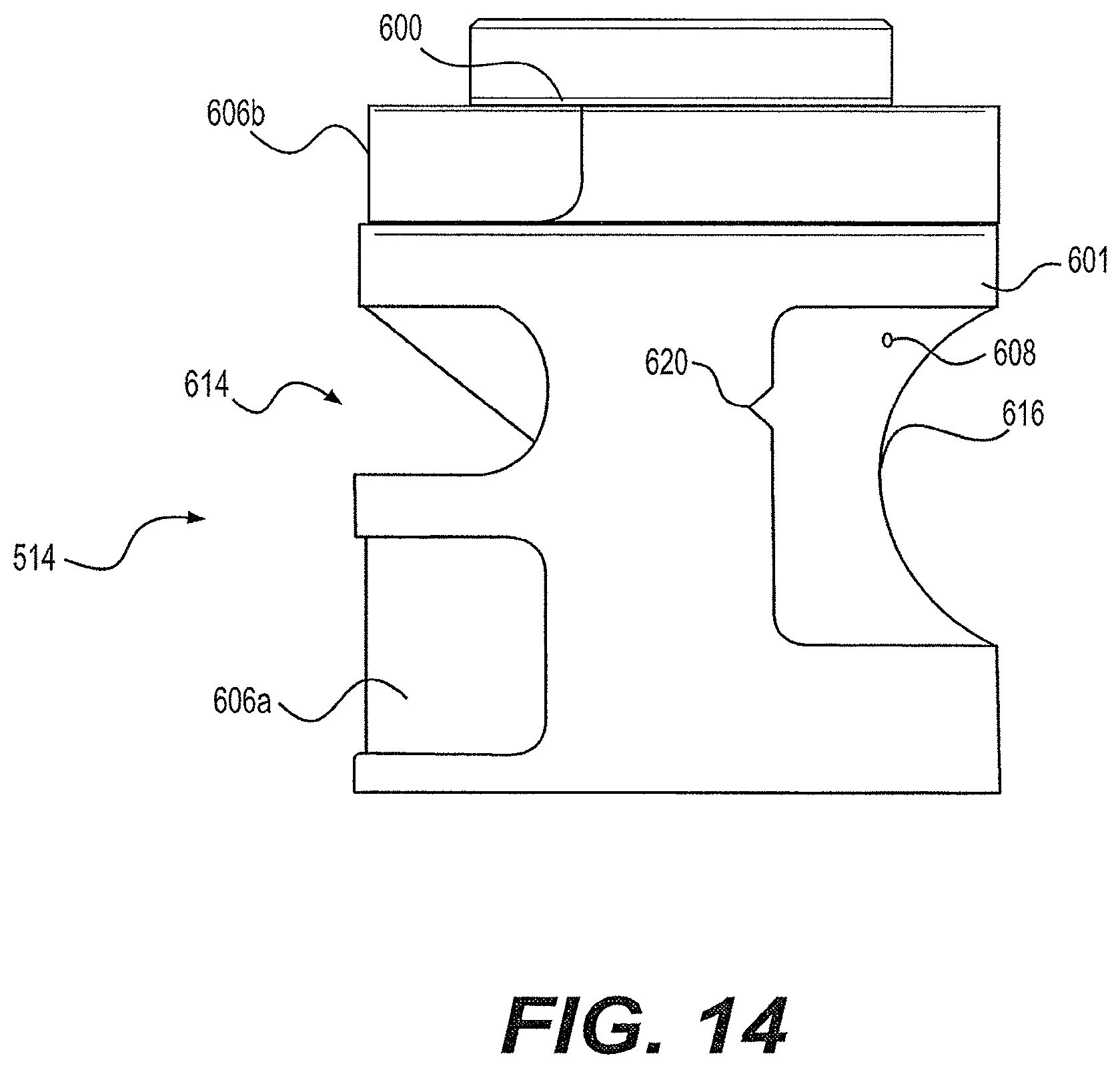
D00014

D00015

D00016
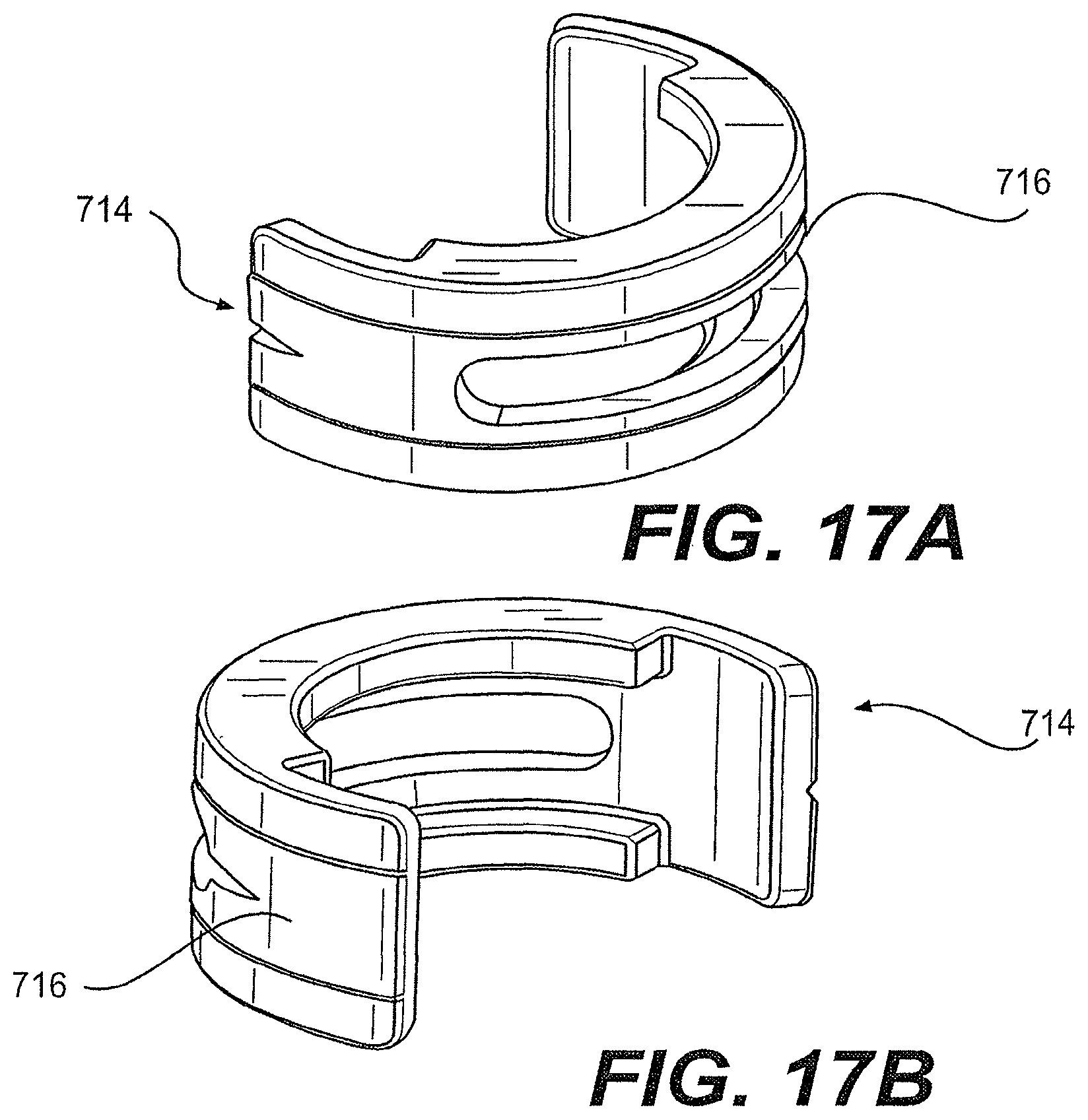
D00017
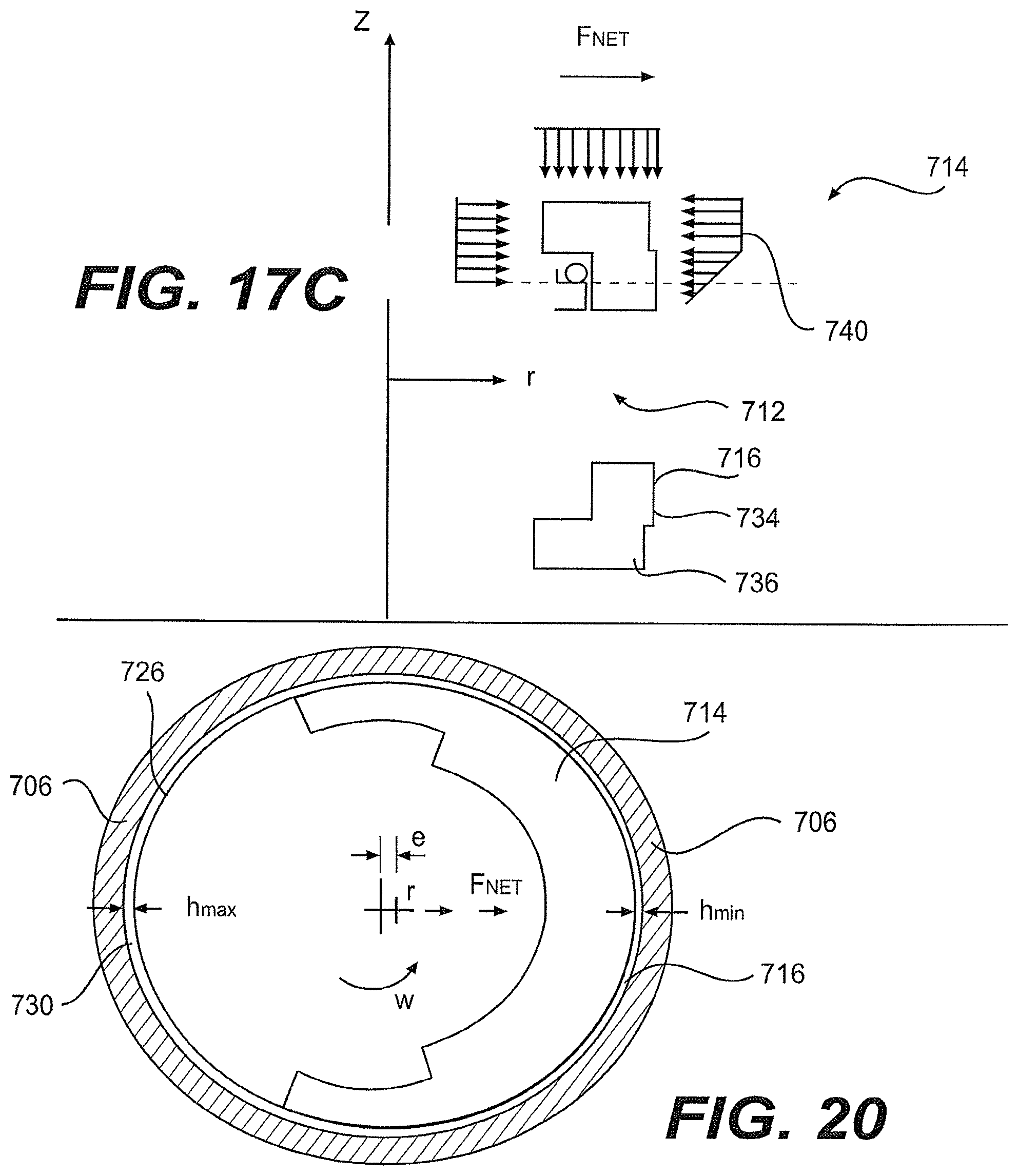
D00018

D00019

D00020
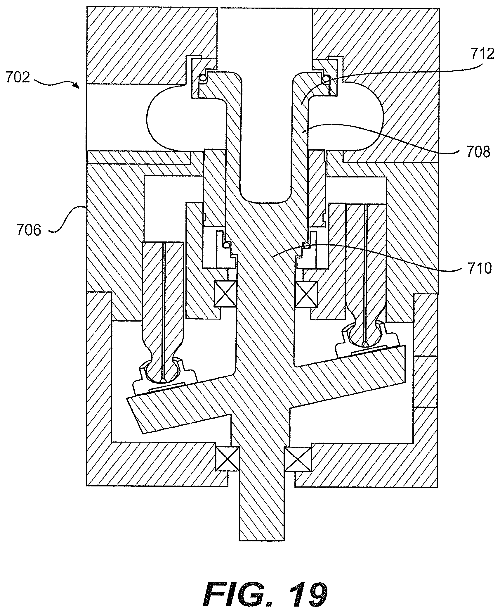
D00021

D00022
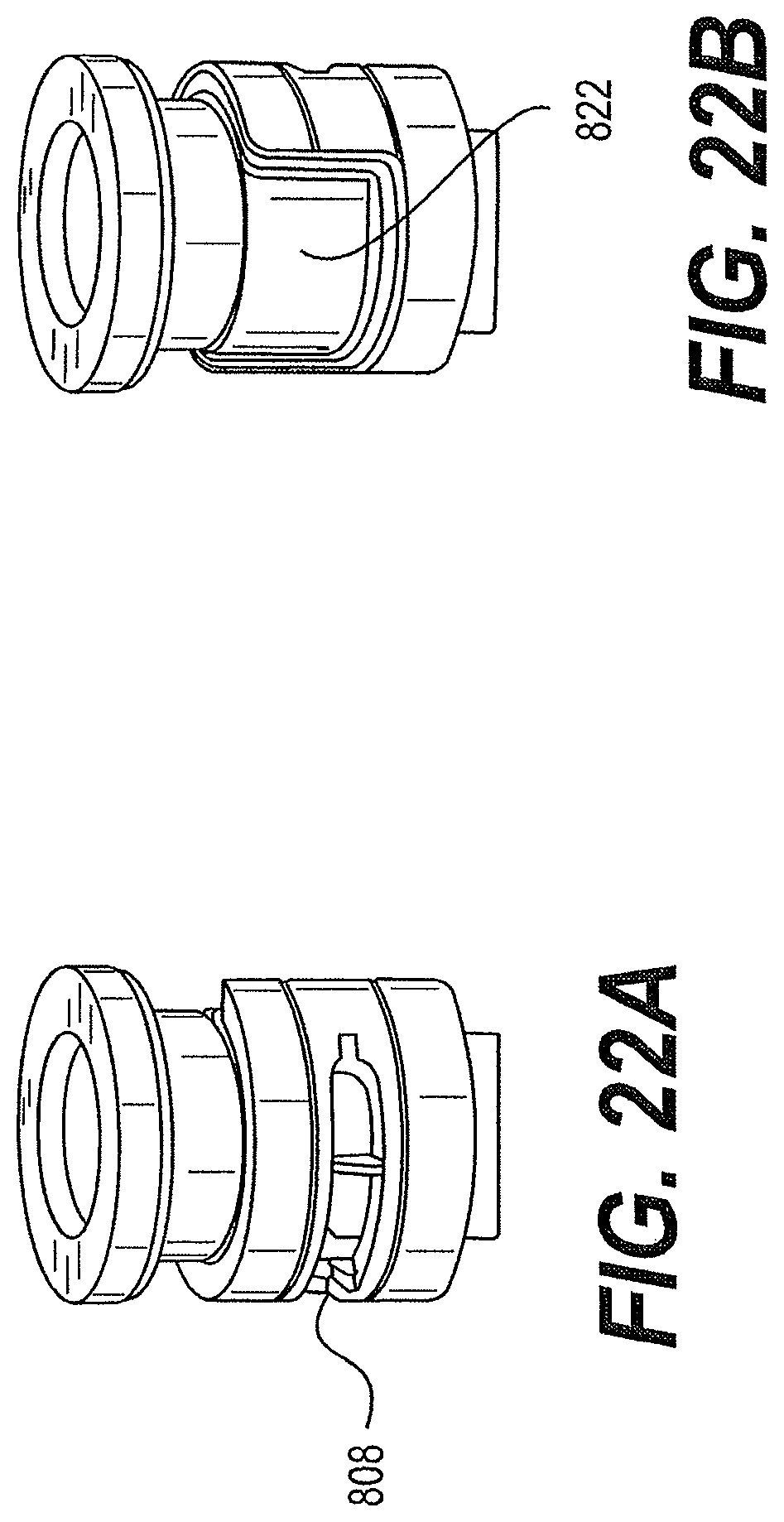
D00023
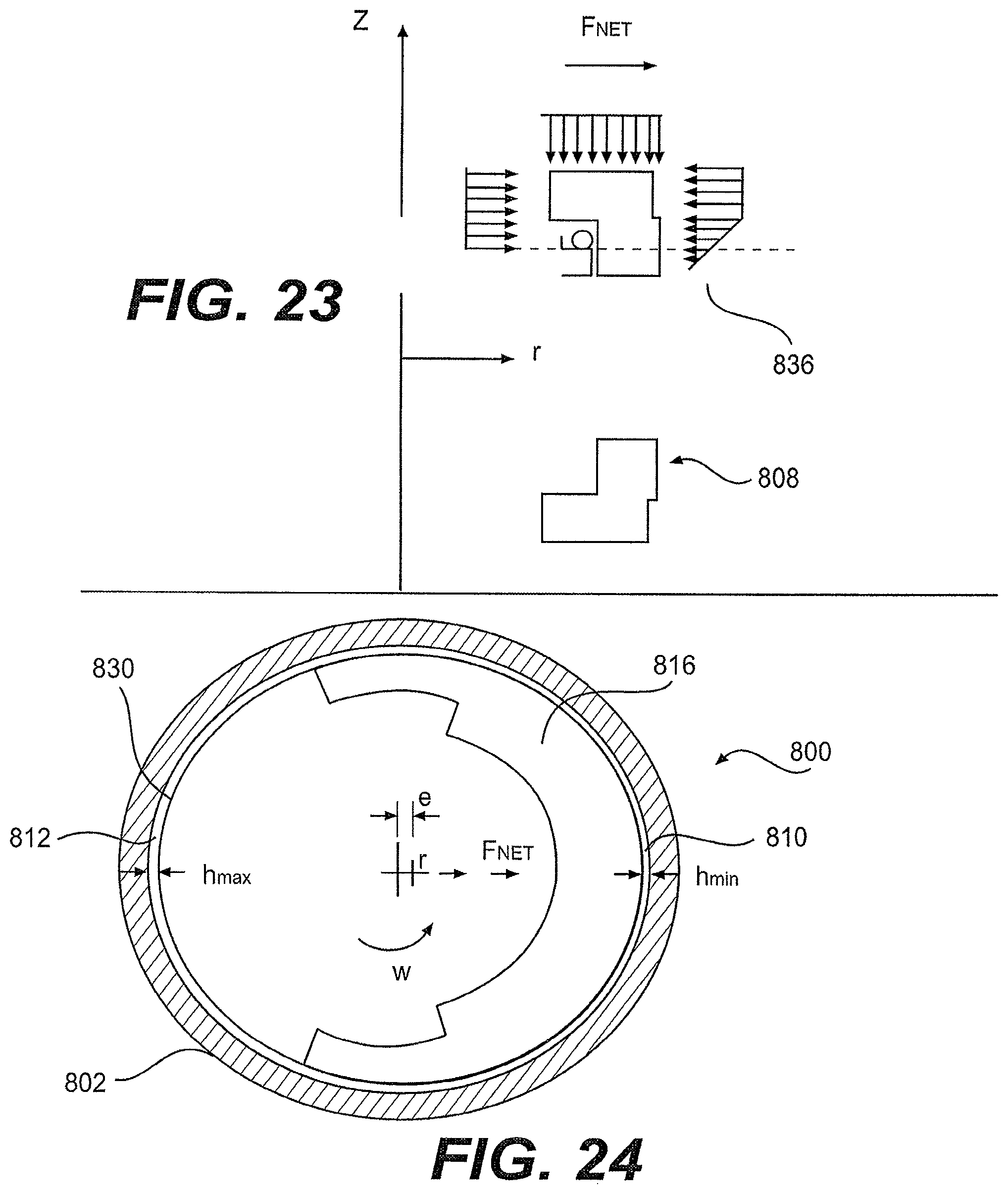
D00024

D00025
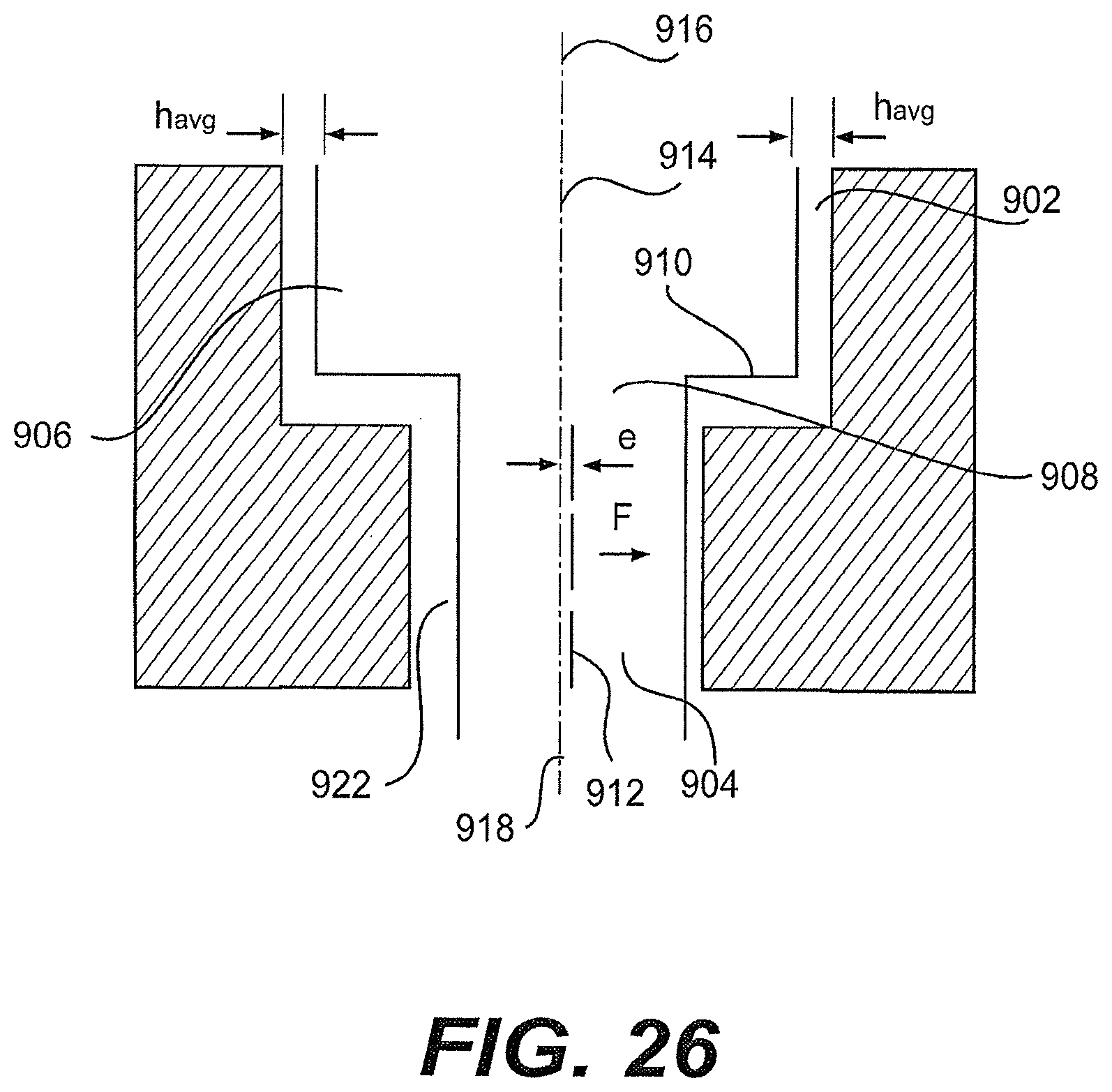
D00026
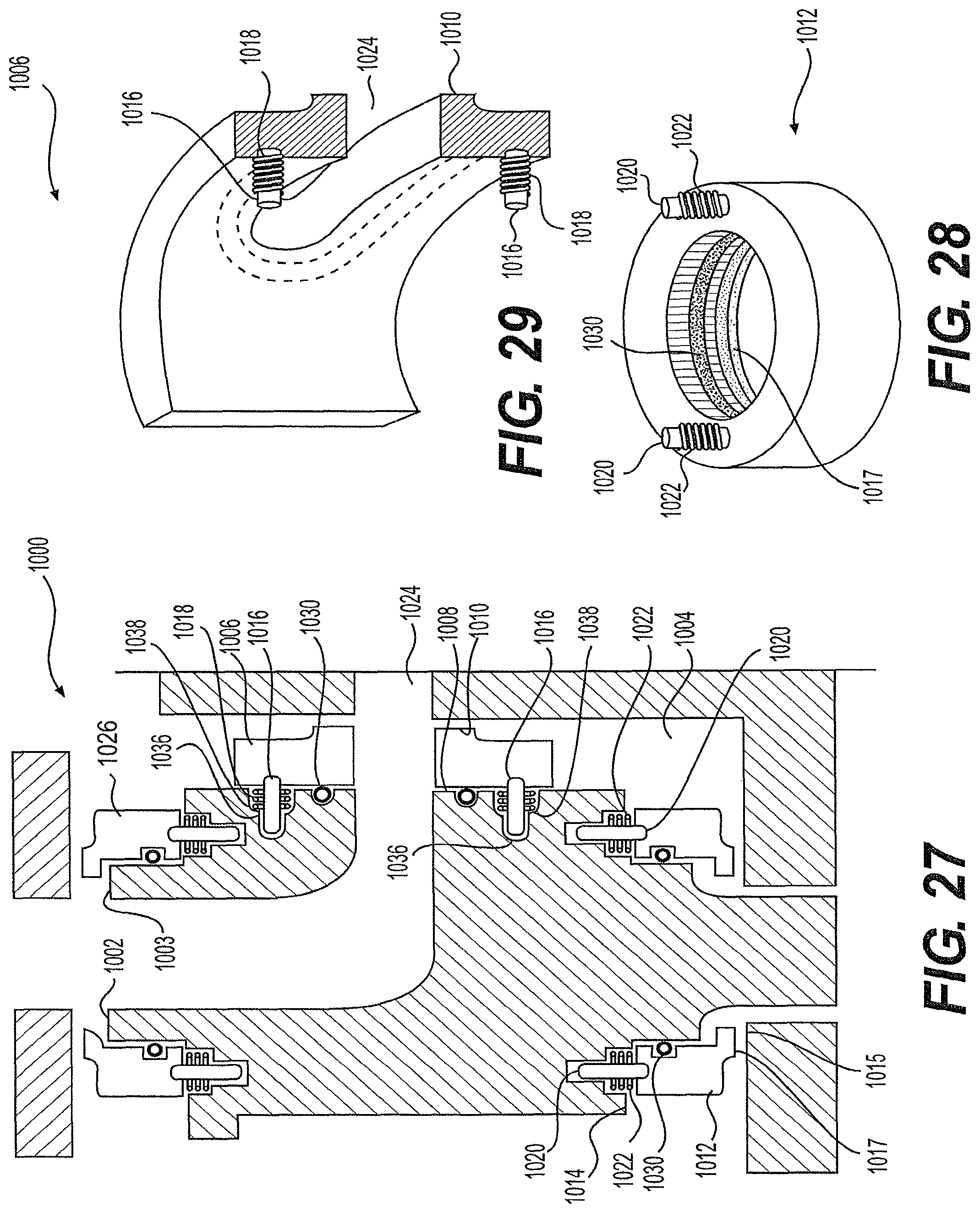
D00027

D00028
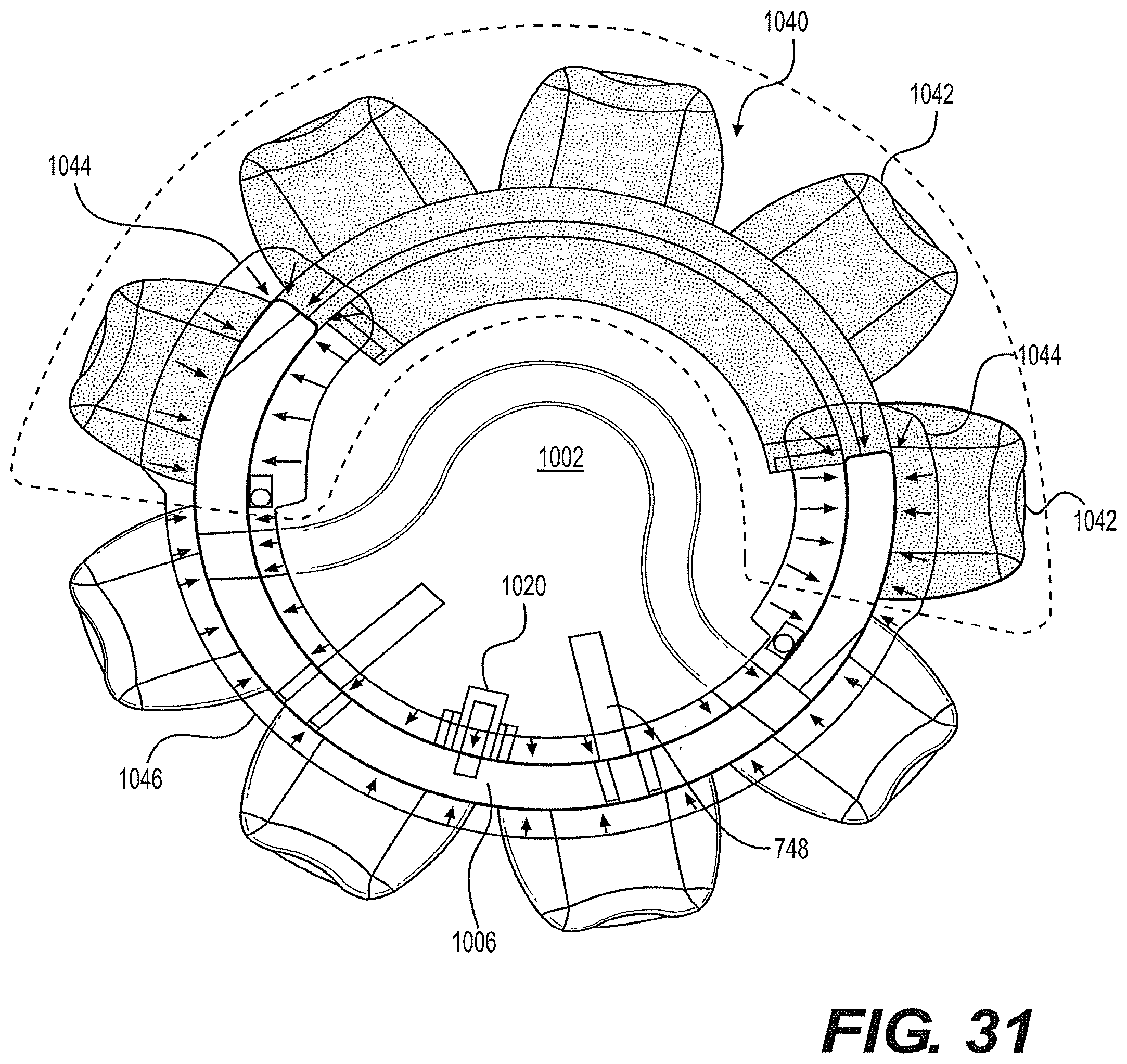
D00029

XML
uspto.report is an independent third-party trademark research tool that is not affiliated, endorsed, or sponsored by the United States Patent and Trademark Office (USPTO) or any other governmental organization. The information provided by uspto.report is based on publicly available data at the time of writing and is intended for informational purposes only.
While we strive to provide accurate and up-to-date information, we do not guarantee the accuracy, completeness, reliability, or suitability of the information displayed on this site. The use of this site is at your own risk. Any reliance you place on such information is therefore strictly at your own risk.
All official trademark data, including owner information, should be verified by visiting the official USPTO website at www.uspto.gov. This site is not intended to replace professional legal advice and should not be used as a substitute for consulting with a legal professional who is knowledgeable about trademark law.