Microfluidic Chip, Device And Method For Chemiluminescence Immunoassay
YANG; Zhaokun ; et al.
U.S. patent application number 16/080179 was filed with the patent office on 2020-10-22 for microfluidic chip, device and method for chemiluminescence immunoassay. The applicant listed for this patent is BEIJING BOE DISPLAY TECHNOLOGY CO., LTD, BOE TECHNOLOGY GROUP CO., LTD. Invention is credited to Sha LIU, Yun QIU, Xiao SUN, Zhaokun YANG.
| Application Number | 20200330986 16/080179 |
| Document ID | / |
| Family ID | 1000004992290 |
| Filed Date | 2020-10-22 |

| United States Patent Application | 20200330986 |
| Kind Code | A1 |
| YANG; Zhaokun ; et al. | October 22, 2020 |
MICROFLUIDIC CHIP, DEVICE AND METHOD FOR CHEMILUMINESCENCE IMMUNOASSAY
Abstract
The present disclosure provides a microfluidic chip, a device and a method for chemiluminescence immunoassay. The microfluidic chip includes a base plate, as well as a first liquid inlet channel, a second liquid inlet channel, a third liquid inlet channel, an immune reaction cell, and a luminescent reaction cell formed on a first surface of the base plate. An outlet end of the immune reaction cell is in communication with a liquid inlet end of the luminescent reaction cell, and a primer is disposed in the immune reaction cell for immobilizing an antigen-antibody complex generated in the immune reaction cell.
| Inventors: | YANG; Zhaokun; (Beijing, CN) ; QIU; Yun; (Beijing, CN) ; LIU; Sha; (Beijing, CN) ; SUN; Xiao; (Beijing, CN) | ||||||||||
| Applicant: |
|
||||||||||
|---|---|---|---|---|---|---|---|---|---|---|---|
| Family ID: | 1000004992290 | ||||||||||
| Appl. No.: | 16/080179 | ||||||||||
| Filed: | January 22, 2018 | ||||||||||
| PCT Filed: | January 22, 2018 | ||||||||||
| PCT NO: | PCT/CN2018/073606 | ||||||||||
| 371 Date: | August 27, 2018 |
| Current U.S. Class: | 1/1 |
| Current CPC Class: | B01L 3/502715 20130101; G01N 33/542 20130101; B01L 2300/0861 20130101; G01N 21/76 20130101; B01L 2200/10 20130101 |
| International Class: | B01L 3/00 20060101 B01L003/00; G01N 21/76 20060101 G01N021/76; G01N 33/542 20060101 G01N033/542 |
Foreign Application Data
| Date | Code | Application Number |
|---|---|---|
| Jul 5, 2017 | CN | 201710542327.5 |
Claims
1. A microfluidic chip for chemiluminescence immunoassay, comprising: a base plate, and a first liquid inlet channel, a second liquid inlet channel, a third liquid inlet channel, an immune reaction cell, and a luminescent reaction cell formed on a first surface of the base plate, wherein an outlet end of the immune reaction cell is in communication with a liquid inlet end of the luminescent reaction cell, and a primer is in the immune reaction cell for immobilizing an antigen-antibody complex generated in the immune reaction cell, wherein a liquid outlet end of the first liquid inlet channel is in communication with a liquid inlet end of the immune reaction cell, and the first liquid inlet channel is configured to introduce an antigen to be tested and an antibody into the immune reaction cell, wherein a liquid outlet end of the second liquid inlet channel is in communication with the liquid inlet end of the immune reaction cell, wherein the second liquid inlet channel is configured to introduce an alkaline solution into the immune reaction cell, wherein a liquid outlet end of the third liquid inlet channel is in communication with the liquid inlet end of the luminescent reaction cell, and wherein the third liquid inlet channel is configured to introduce an oxidant solution into the luminescent reaction cell.
2. The microfluidic chip according to claim 1, further comprising: a cover plate on a second surface of the base plate, wherein the second surface is opposite to the first surface, wherein the base plate comprises a reserved area and a non-reserved area, wherein the cover plate covers the non-reserved area; wherein the first liquid inlet channel, the second liquid inlet channel, the third liquid inlet channel, the immune reaction cell and the luminescent reaction cell are in the non-reserved area, and wherein a liquid inlet end of the first liquid inlet channel, a second liquid inlet channel, and a third liquid inlet channel extend into the reserved area.
3. The microfluidic chip according to claim 2, further comprising: a heating electrode on a side of the cover plate adjacent to the base plate, wherein an orthographic projection of the heating electrode on the base plate at least covers the immune reaction cell.
4. The microfluidic chip according to claim 1, wherein a plurality of liquid pumps are at the liquid inlet end of the first liquid inlet channel, the liquid inlet end of the second liquid inlet channel, and the liquid inlet end of the third liquid inlet channel, respectively, and wherein the plurality of liquid pumps are configured to deliver corresponding liquids to the liquid inlet end of the first liquid inlet channel, the liquid inlet end of the second liquid inlet channel, and the liquid inlet end of the third liquid inlet channel, respectively.
5. The microfluidic chip according to claim 1, wherein the base plate and the cover plate are connected by a bonding process.
6. The microfluidic chip according to claim 1, wherein the first liquid inlet channel comprises: a first sub-channel; a second sub-channel; and a third sub-channel, wherein a liquid outlet end of the first sub-channel, a liquid outlet end of the second sub-channel, and a liquid outlet end of the third sub-channel are concentrated at a first node, wherein the first node is in communication with the liquid inlet end of the immune reaction cell through a connection sub-channel, and the first sub-channel, the second sub-channel, and the third sub-channel are configured to introduce an antigen to be tested, a first antibody, and a second antibody into the immune reaction cell respectively.
7. The microfluidic chip according to claim 6, wherein the first antibody comprises a DNA-labeled antibody and the second antibody comprises an acridinium ester-labeled antibody.
8. The microfluidic chip according to claim 6, wherein the first liquid inlet channel further comprises: a fourth sub-channel; wherein a liquid outlet end of the fourth sub-channel is in communication with the connection sub-channel, and wherein the fourth sub-channel is configured to introduce a cleaning solution into the immune reaction cell.
9. The microfluidic chip according to claim 1, wherein the immune reaction cell comprises one or more fifth sub-channels that are connected end to end, and wherein the luminescent reaction cell comprises one or more sixth sub-channels that are connected end to end.
10. The microfluidic chip according to claim 9, wherein a length of the immune reaction cell is L1, and a length of the luminescent reaction cell is L2, and wherein 2.times.L1<L2.
11. The microfluidic chip according to claim 6, wherein cross-sectional shapes of the first sub-channel, the second sub-channel, the third sub-channel, the second liquid inlet channel, and the third liquid inlet channel are semi-circular.
12. The microfluidic chip according to claim 11, wherein a diameter of the cross-sectional shape ranges from 1 .mu.m to 20 .mu.m.
13. The microfluidic chip according to claim 9, wherein a cross-sectional shape of the fifth sub-channel out of the plurality of cross-sectional shapes and a cross-sectional shape of the sixth sub-channel out of the plurality of cross-sectional shapes are semi-circular.
14. The microfluidic chip of claim 13, wherein respective diameters of ones of the plurality of cross-sectional shapes range from 1 .mu.m to 20 .mu.m.
15. A device for chemiluminescence immunoassay, comprising: a microfluidic chip according to claim 1.
16. A method for chemiluminescence immunoassay, the method comprising: injecting an antigen to be tested and an antibody into an immune reaction cell through a first liquid inlet channel of a microfluidic chip, such that an antigen-antibody complex is generated by an immune reaction between the antigen to be tested and the antibody, the antigen-antibody complex being immobilized on a primer in the immune reaction cell; injecting an alkaline solution into the immune reaction cell through a second liquid inlet channel of the microfluidic chip, such that double strands unwind between the antigen-antibody complex and the primer, thereby the antigen-antibody complex and the alkaline solution flow into the luminescent reaction cell; and injecting an oxidant solution into the luminescent reaction cell through third liquid inlet channel of the microfluidic chip, such that the antigen-antibody complex decomposes to emit light under influences of the oxidant solution and the alkaline solution, wherein emitted photons are detected by a photon counter.
17. The method according to claim 16, wherein the first liquid inlet channel of the microfluidic chip comprises a fourth sub-channel, and wherein a liquid outlet end of the fourth sub-channel is in communication with a liquid inlet end of the immune reaction cell through a connection sub-channel, the method further comprising: injecting a cleaning solution into the immune reaction cell through the fourth sub-channel, before injecting the alkaline solution into the immune reaction cell through the second liquid inlet channel, such that the antigen to be tested and the antibody, which are not reacted in the connection sub-channel and the immune reaction cell, are washed out from a liquid outlet end of the immune reaction cell.
18. The microfluidic chip according to claim 7, wherein respective cross-sectional shapes of the first sub-channel, the second sub-channel, the third sub-channel, the second liquid inlet channel, and the third liquid inlet channel are semi-circular.
19. The microfluidic chip according to claim 8, wherein respective cross-sectional shapes of the first sub-channel, the second sub-channel, the third sub-channel, the second liquid inlet channel, and the third liquid inlet channel are semi-circular.
20. The microfluidic chip according to claim 10, wherein respective cross-sectional shapes of the fifth sub-channel and the sixth sub-channel are semi-circular.
Description
CROSSE REFERENCES TO RELATED APPLICATION(S)
[0001] The present application claims the benefit of Chinese Patent Application No. 201710542327.5 filed on Jul. 5, 2017, the entire disclosure of which is incorporated herein by reference.
TECHNICAL FIELD
[0002] The present disclosure relates to the field of medical technology, in particular to a microfluidic chip, a device and a method for chemiluminescence immunoassay.
BACKGROUND
[0003] At present, immunodiagnosis is mainly performed by a chemiluminescence immunoassay analyzer. The existing instrument includes an immunoreaction device and a chemiluminescence analyzer. In the immunoreaction device of this instrument, a conventional test tube is used as a reaction vessel, and the separation between the reaction product and the reagent is realized by the micro-bead technology, which requires a large amount of test reagents and magnetic beads. In addition, since the test tube is used as a reaction vessel, the amount of reagents required is large and the cost is high.
[0004] In addition, the existing chemiluminescence immunoassay analyzers are large in size and inconvenient to store.
SUMMARY
[0005] According to an aspect of the present disclosure, a microfluidic chip for chemiluminescence immunoassay is provided. The microfluidic chip includes a base plate, as well as a first liquid inlet channel, a second liquid inlet channel, a third liquid inlet channel, an immune reaction cell, and a luminescent reaction cell formed on a first surface of the base plate. An outlet end of the immune reaction cell is in communication with a liquid inlet end of the luminescent reaction cell, and a primer is disposed in the immune reaction cell for immobilizing an antigen-antibody complex generated in the immune reaction cell. A liquid outlet end of the first liquid inlet channel is in communication with a liquid inlet end of the immune reaction cell, and the first liquid inlet channel is used to introduce an antigen to be tested and an antibody into the immune reaction cell. A liquid outlet end of the second liquid inlet channel is in communication with the liquid inlet end of the immune reaction cell, and the second liquid inlet channel is used to introduce an alkaline solution into the immune reaction cell. A liquid outlet end of the third liquid inlet channel is in communication with the liquid inlet end of the luminescent reaction cell, and the third liquid inlet channel is used to introduce an oxidant solution into the luminescent reaction cell.
[0006] Optionally, the microfluidic chip for chemiluminescence immunoassay further includes: a cover plate disposed on a second surface of the base plate, wherein the second surface is opposite to the first surface, and the base plate includes a reserved area and a non-reserved area. The first liquid inlet channel, the second liquid inlet channel, the third liquid inlet channel, the immune reaction cell and the luminescent reaction cell are all located in the non-reserved area. The cover plate covers the non-reserved area. The liquid inlet ends of the first liquid inlet channel, the second liquid inlet channel, and the third liquid inlet channel extend into the reserved area.
[0007] Optionally, the microfluidic chip for chemiluminescence immunoassay further includes: a heating electrode disposed on a side of the cover plate adjacent to the base plate, wherein an orthographic projection of the heating electrode on the base plate at least covers the immune reaction cell.
[0008] Optionally, in the microfluidic chip for chemiluminescence immunoassay as proposed above, liquid pumps are disposed at the liquid inlet ends of the first liquid inlet channel, the second liquid inlet channel, and the third liquid inlet channel, wherein the liquid pumps are used to deliver corresponding liquids to each of the liquid inlet ends.
[0009] Optionally, in the microfluidic chip for chemiluminescence immunoassay as proposed above, the base plate and the cover plate are connected by a bonding process.
[0010] Optionally, in the microfluidic chip for chemiluminescence immunoassay as proposed above, the first liquid inlet channel includes: a first sub-channel, a second sub-channel, and a third sub-channel. Liquid outlet ends of the first sub-channel, the second sub-channel, and the third sub-channel are concentrated at a first node, wherein the first node is in communication with the liquid inlet end of the immune reaction cell through a connection sub-channel. The first sub-channel, the second sub-channel, and the third sub-channel are used to introduce an antigen to be tested, a first antibody, and a second antibody into the immune reaction cell respectively.
[0011] Optionally, in the microfluidic chip for chemiluminescence immunoassay as proposed above, the first antibody is a DNA-labeled antibody, and the second antibody is an acridinium ester-labeled antibody.
[0012] Optionally, in the microfluidic chip for chemiluminescence immunoassay as proposed above, the first liquid inlet channel further includes: a fourth sub-channel. A liquid outlet end of the fourth sub-channel is in communication with the connection sub-channel, and the fourth sub-channel is used to introduce a cleaning solution into the immune reaction cell.
[0013] Optionally, in the microfluidic chip for chemiluminescence immunoassay as proposed above, the immune reaction cell includes a single fifth sub-channel or a plurality of fifth sub-channels connected end to end. The luminescent reaction cell includes a single sixth sub-channel or a plurality of sixth sub-channels connected end to end. Optionally, at least one of the fifth sub - channel and the sixth sub-channel has a linear shape.
[0014] Optionally, in the microfluidic chip for chemiluminescence immunoassay as proposed above, a length of the immune reaction cell is L1, and a length of the luminescent reaction cell is L2, wherein 2.times.L1<L2.
[0015] Optionally, in the microfluidic chip for chemiluminescence immunoassay as proposed above, cross-sectional shapes of each of the sub-channels (including the first sub-channel, the second sub-channel, the third sub-channel, the fourth sub-channel, the fifth sub-channel, and the sixth sub-channel), the second liquid inlet channel, and the third liquid inlet channel are all semi-circular.
[0016] Optionally, in a specific example of the above embodiment, a diameter of the semi-circular cross section ranges from 1 um to 20 um.
[0017] According to another aspect of the present disclosure, a device for chemiluminescence immunoassay is also provided. The device includes the microfluidic chip as described in any of the above embodiments.
[0018] According to yet another aspect of the present disclosure, a method for chemiluminescence immunoassay is further provided. The method is based on the microfluidic chip as described in any of the above embodiments, and includes the steps of: injecting an antigen to be tested and an antibody into the immune reaction cell through a first liquid inlet channel, such that an antigen-antibody complex is generated by an immune reaction between the antigen to be tested and the antibody , the antigen-antibody complex being immobilized on a primer in the immune reaction cell; injecting an alkaline solution into the immune reaction cell through a second liquid inlet channel, such that double strands unwind between the antigen-antibody complex and the primer, thereby the antigen - antibody complex and the alkaline solution flowing into a luminescent reaction cell; and injecting an oxidant solution into the luminescent reaction cell through a third liquid inlet channel, such that the antigen-antibody complex decomposes to emit light under influences of the oxidant solution and the alkaline solution, wherein emitted photons can be detected by a photon counter located below the microfluidic chip.
[0019] Optionally, in a specific embodiment, the first liquid inlet channel of the microfluidic chip includes a fourth sub-channel, wherein a liquid outlet end of the fourth sub-channel is in communication with a liquid inlet end of the immune reaction cell through a connection sub-channel. In such a case, the method for chemiluminescence immunoassay further includes the step of: injecting a cleaning solution into the immune reaction cell through the fourth sub-channel, before injecting the alkaline solution into the immune reaction cell through the second liquid inlet channel, such that the antigen to be tested and the antibody, which are not reacted in the connection sub-channel and the immune reaction cell, are washed out from a liquid outlet end of the immune reaction cell.
BRIEF DESCRIPTION OF THE DRAWINGS
[0020] FIG. 1 is a top view of a microfluidic chip according to an embodiment of the present disclosure;
[0021] FIG. 2 is a schematic cross-sectional view taken along the line A-A in FIG. 1;
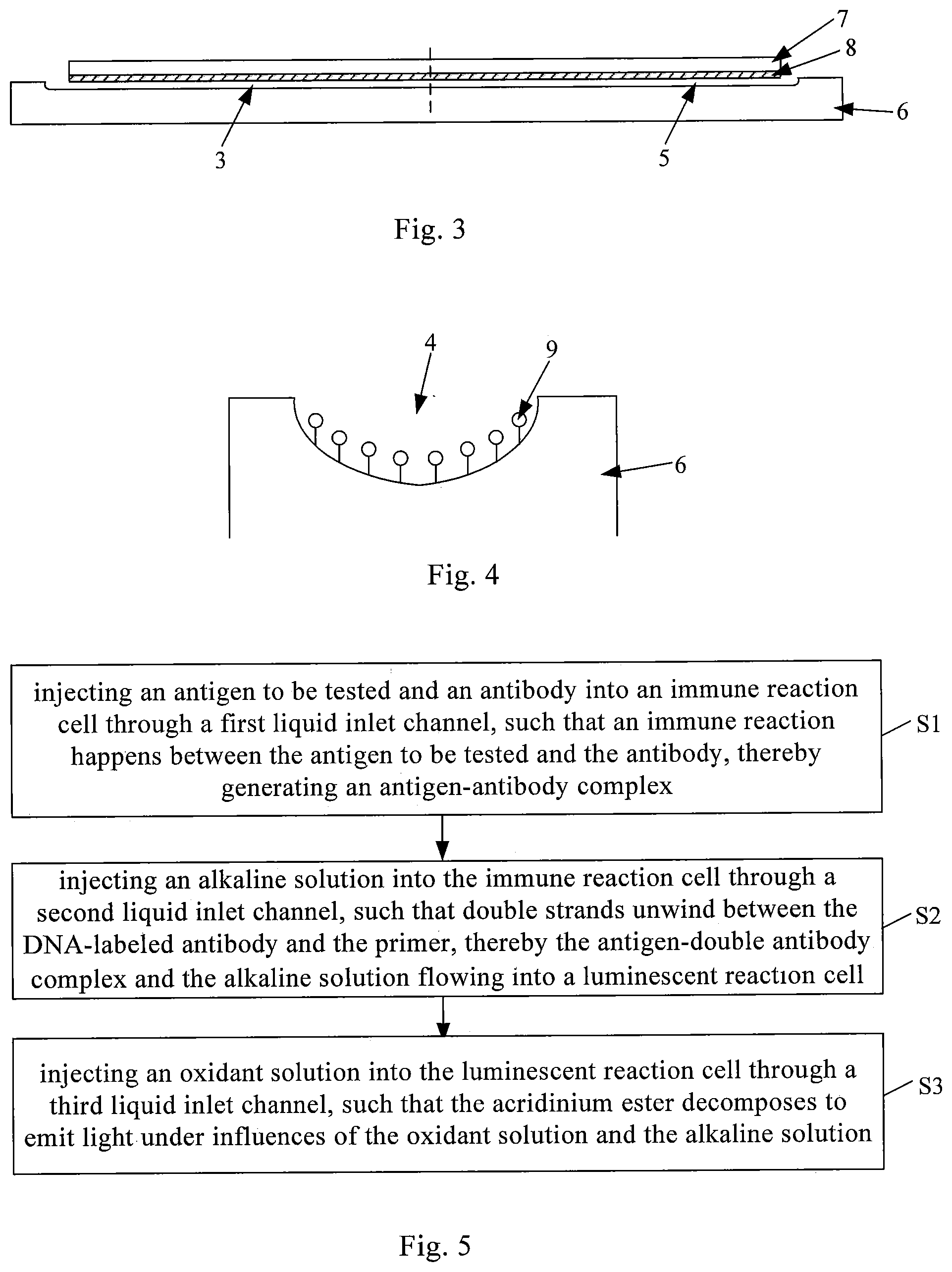
[0022] FIG. 3 is a schematic cross-sectional view taken along the line B-B in FIG. 1;
[0023] FIG. 4 is a schematic cross-sectional view of an immune reaction cell in a microfluidic chip according to an embodiment of the present disclosure;
[0024] FIG. 5 is a flow chart of a method for chemiluminescence immunoassay according to an embodiment of the present disclosure; and
[0025] FIG. 6 is a flow chart of a method for chemiluminescence immunoassay according to another embodiment of the present disclosure.
DETAILED DESCRIPTION OF THE EMBODIMENTS
[0026] To enable those skilled in the art to understand technical solutions of the present disclosure in a better way, a microfluidic chip, a device and a method for chemiluminescence immunoassay provided by the present disclosure will be described in detail below with reference to the drawings.
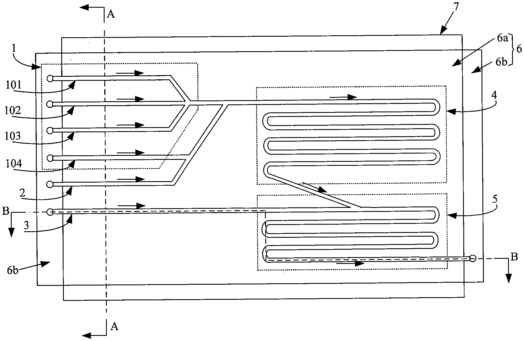
[0027] FIG. 1 is a top view of a microfluidic chip according to an embodiment of the present disclosure. FIG. 2 is a cross-sectional view taken along the line A-A in FIG. 1. FIG. 3 is a cross-sectional view taken along the line B-B in FIG. 1. FIG. 4 is a schematic cross-sectional view of an immune reaction cell in a microfluidic chip according to an embodiment of the present disclosure. As shown in FIG. 1 to FIG. 4, the microfluidic chip can be used for chemiluminescence immunoassay, and the microfluidic chip includes: a base plate 6, as well as a first liquid inlet channel 1, a second liquid inlet channel 2, third liquid inlet channel 3, immune reaction cell 4, and luminescent reaction cell 5 formed on a first surface of the base plate 6.
[0028] An outlet end of the immune reaction cell 4 is in communication with a liquid inlet end of the luminescent reaction cell 5, and a primer 9 (such as a small segment of single-stranded DNA or RNA) is disposed in the immune reaction cell 4 for immobilizing an antigen-antibody complex generated in the immune reaction cell 4. As an example, one end of the primer 9 is fixed to a wall of the immune reaction cell 4 by a surface modification technique.
[0029] A liquid outlet end of the first liquid inlet channel 1 is in communication with a liquid inlet end of the immune reaction cell 4, and the first liquid inlet channel 1 is used to introduce an antigen to be tested and two antibodies into the immune reaction cell 4.
[0030] A liquid outlet end of the second liquid inlet channel 2 is in communication with the liquid inlet end of the immune reaction cell 4, and the second liquid inlet channel 2 is used to introduce an alkaline solution into the immune reaction cell 4.
[0031] A liquid outlet end of the third liquid inlet channel 3 is in communication with the liquid inlet end of the luminescent reaction cell 5, and the third liquid inlet channel 3 is used to introduce an oxidant solution into the luminescent reaction cell 5.
[0032] The immune reaction cell 4 is used for the immune reaction (in which the antibody and the antigen specifically combine) between the antigen to be tested and the antibody, so as to generate the antigen-antibody complex. In this embodiment, a dual antibody sandwiched approach is employed in which the antibody includes two types. Specifically, the two types of antibodies include a DNA-labeled antibody and an acridinium ester-labeled antibody. In this case, the product in the immune reaction cell 4 is an antigen-dual antibody complex.
[0033] The luminescent reaction cell 5 is used for the luminescence reaction of the antigen-dual antibody complex under influences of an oxidant and a weak alkaline environment. In such a case, the emitted photons can be detected by a photon counter located below the microfluidic chip for analysis of the amount of antigen to be tested.
[0034] In the present disclosure , an etching process (e.g., a chemical etching process, a laser etching process) can be performed on a surface of a base plate 6, so as to form a first liquid inlet channel 1, a second liquid inlet channel 2, a third liquid inlet channel 3, an immune reaction cell 4 and a luminescent reaction cell 5.
[0035] In the present disclosure, a microfluidic chip is used to perform a series of processes, such as injection, mixing, reaction, and detection, in the chemiluminescence immunoassay. Compared to the case where a conventional test tube is used as a reaction vessel in a conventional scheme, the technical solution proposed in the present disclosure can greatly reduce the amount of reagents used in the analysis process and reduce the analysis cost. In addition, the microfluidic chip is small in size, light in weight, and convenient to store.
[0036] In an embodiment, optionally, the microfluidic chip further includes: a cover plate 7 disposed on a second surface of the base plate 6, wherein the second surface is opposite to the first surface on which the liquid inlet channels and the reaction cells are disposed. The base plate 6 is further divided into a reserved area 6b and a non-reserved area 6a. Each of the liquid inlet channels and the two reaction cells is located in the non-reserved area 6a, and the cover plate 7 covers the non-reserved area 6a. Further, the liquid inlet ends of the first liquid inlet channel 1, the second liquid inlet channel 2, and the third liquid inlet channel 3 extend into the reserved area 6b. By providing the cover plate, it may effectively prevent the liquid in each of the liquid inlet channels and the reaction cells from overflowing.
[0037] It should be noted that, in the drawings, the reserved area 6b is shown as being located at two peripheral areas of the non-reserved area 6a opposite to each other , but this is merely an example and does not impose any limitation on the technical solution of the present disclosure.
[0038] In an embodiment, optionally, materials suitable for the base plate 6 and the cover plate 7 are both glass. In this case, the base plate 6 and the cover plate 7 can be connected by a glass-to-glass bonding process. Thus, there is no need to use an adhesive or a fixed structure.
[0039] The specific process for implementing chemiluminescence immunoassay using the microfluidic chip as provided by the present disclosure will be described in detail below.
[0040] First, an antigen to be tested, a DNA-labeled antibody, and an acridinium ester - labeled antibody are injected into the immune reaction cell 4 through the first liquid inlet channel 1. An antigen-dual antibody complex is generated by an immune reaction between these three in the immune reaction cell 4.
[0041] In an embodiment, the antigen to be tested, the DNA-labeled antibody, and the acridinium ester - labeled antibody may be mixed first , and then the mixed solution is injected into the immune reaction cell 4 through the first liquid inlet channel 1.
[0042] If the method of mixing first and then injection is employed, a large amount of reagents will be required in the pre-mixing process. In order to solve this problem, in an embodiment, optionally, the first liquid inlet channel 1 includes: a first sub-channel 101, a second sub-channel 102, and a third sub-channel 103. The liquid inlet ends of the first sub-channel 101, the second sub-channel 102, and the third sub-channel 103 extend independently into a reserved area, respectively. The liquid outlet ends of the first sub-channel 101, the second sub-channel 102, and the third sub-channel 103 are concentrated at a first node, wherein the first node is in communication with a liquid inlet end of the immune reaction cell 4 through a connection sub-channel. The first sub-channel 101, the second sub-channel 102, and the third sub-channel 103 are used to introduce the antigen to be tested, the DNA-labeled antibody (first antibody), and the acridinium ester-labeled antibody (second antibody) into the immune reaction cell 4, respectively.
[0043] In an embodiment, three independent sub-channels are provided for injecting the antigen to be tested and the two antibodies, respectively, thereby achieving injection first and then mixing, and greatly reducing the amount of reagents. In addition, since the antigen to be tested and the two antibodies are injected through separate sub - channels , the amount of antigen to be tested and the amount of two antibodies can be individually controlled.
[0044] Optionally, liquid pumps (not shown) are disposed at the liquid inlet ends of the first liquid inlet channel 1 (including the first sub-channel 101, the second sub-channel 102, and the third sub-channel 103). In this way, precise control over the amount of injected reagents can be achieved by delivering corresponding liquids to the liquid inlet ends of the first liquid inlet channel through the liquid pumps.
[0045] Optionally, the cross-sectional shapes of the first sub-channel 101, the second sub - channel 102, and the third sub-channel 103 are semi-circular, and diameters of the first sub-channel 101, the second sub-channel 102, and the third sub-channel 103 range from 1 um to 20 um.
[0046] Optionally, a heating electrode 8 is disposed on a side of the cover plate 7 facing the base plate 6, and the heating electrode 8 covers at least an area corresponding to the immune reaction cell 4. By applying a certain current to the heating electrode 8 such that heat is generated by the heating electrode 8, it is ensured that the ambient temperature of the immune reaction cell 4 is at a preset value (generally 37.degree. C.). Thus, the immune reaction between the antigen to be tested and the two antibodies in the immune reaction cell 4 is promoted. Optionally, materials suitable for the heating electrode 8 include at least one of gold, silver, and aluminum. The heating electrode 8 can be formed on a surface of the cover plate 7 by sputtering or plating.
[0047] It should be noted that when the heating electrode 8 made of metal material is disposed on the side of the cover plate 7 facing the base plate 6, the base plate 6 and the cover plate 7 can be connected by a metal-glass bonding process.
[0048] In addition, in the drawings, the heating electrode 8 is illustrated as covering the entire cover plate 7, but this is only an exemplary solution. In this way, the temperature of the entire microfluidic chip can be made to be at a preset value, thereby being more favorable for maintaining a stable temperature of the immune reaction cell 4.
[0049] After generating an antigen-dual antibody complex by the immune reaction between the antigen to be tested, the DNA-labeled antibody and the acridinium ester-labeled antibody, the DNA-labeled antibody in the antigen-dual antibody complex will be complementary to and combined with a primer 9 in the immune reaction cell 4, so as to form a double-stranded structure. In this way, the antigen-dual antibody complex will be immobilized on the primer 9.
[0050] It should be noted that the time duration of the immune reaction can be adjusted according to actual requirements. For example, when performing a rapid test, the time duration of the immune reaction can be set to be about 10 minutes. Instead, when performing a normal test, the time duration of the immune reaction can be set to be about 30 minutes.
[0051] Optionally, the immune reaction cell 4 includes one or more fifth sub-channels. When there is a plurality of fifth sub-channels, all the fifth sub-channels are connected end to end. In this case, the volume of the immune reaction cell 4 is small, and the amount of reagents required is also small accordingly. Optionally, the cross-sectional shape of the fifth sub-channel is semi-circular, and a diameter of the fifth sub-channel ranges from 1 um to 20 um.
[0052] After that, an alkaline solution is injected into the immune reaction cell 4 through the second liquid inlet channel 2, so that double strands unwind between the DNA-labeled antibody and the primer 9, thereby the antigen-dual antibody complex and the alkaline solution flowing into the luminescent reaction cell 5. In a specific example, the alkaline solution is a sodium hydroxide solution. Optionally, the cross-sectional shape of the second liquid inlet channel 2 is semi-circular, and a diameter of the second liquid inlet channel 2 ranges from 1 um to 20 um.
[0053] Optionally, a liquid pump (not shown) is disposed at a liquid inlet end of the second liquid inlet channel 2. In this way, precise control over the amount of the injected alkaline solution can be achieved by delivering the alkaline solution to the liquid inlet end of the second liquid inlet channel through the liquid pump.
[0054] In an embodiment, the antigen to be tested and the antibodies, which are not subjected to an immune reaction, are inevitably present in the immune reaction cell 4. Such unreacted antigen to be tested and antibodies affect the detection result of the luminescence reaction after entering the luminescent reaction cell 5. In order to solve this problem, in an embodiment, optionally, the first liquid inlet channel 1 further includes a fourth sub-channel 104. A liquid inlet end of the fourth sub-channel 104 extends to the reserved area. A liquid outlet end of the fourth sub-channel 104 is in communication with the connection sub-channel. The fourth sub-channel 104 is used to introduce a cleaning solution into the immune reaction cell 4, after the end of the immune reaction and before injecting the alkaline solution into the immune reaction cell 4 through the second liquid inlet channel 2. Specifically, the cleaning solution is deionized water.
[0055] Optionally, the cross-sectional shape of the fourth sub-channel 104 is semi-circular, and a diameter of the fourth sub-channel 104 ranges from 1 um to 20 um.
[0056] When the deionized water is injected into the immune reaction cell 4 through the fourth sub-channel 104, the unreacted antigen to be tested and antibodies in the connection sub-channel and the immune reaction cell 4 will be washed away and be discharged through a waste liquid outlet (i.e., a liquid outlet end of the luminescent reaction cell). In this way, the unreacted antigen to be tested and antibodies can be effectively prevented from entering the luminescent reaction cell 5. In this process, the cleaning time can be adjusted according to actual situations. It should be noted that, when the immune reaction cell 4 is washed with deionized water, since the antigen-dual antibody complex is immobilized on the primer 9, the antigen-dual antibody complex can remain in the immune reaction cell 4, i.e., not being washed away.
[0057] Finally, an oxidant solution is injected into the luminescent reaction cell 5 through the third liquid inlet channel 3. Thus, under influences of the oxidant solution and the alkaline solution , the antigen-dual antibody complex, in particular, the antibody-acridinium ester, decomposes and emits light. Specifically, the oxidant solution is a hydrogen peroxide solution.
[0058] Optionally, a liquid pump (not shown) is disposed at the liquid inlet end of the third liquid inlet channel 3. In this way, precise control over the amount of the injected oxidant solution can be achieved by delivering the oxidant solution to the liquid inlet end of the third liquid inlet channel through the liquid pump.
[0059] Optionally, the cross-sectional shape of the third liquid inlet channel 3 is semi-circular, and a diameter of the third liquid inlet channel 3 ranges from 1 um to 20 um.
[0060] Under influences of the oxidant solution and the alkaline solution, the acridinium ester decomposes, and photons can be continuously and stably emitted. The photon energy released by the emitted light is detected and recorded by a photon counter. After that, the intensity of the light energy is converted to the concentration of the antigen to be tested on a standard curve by a computer processing system.
[0061] Optionally, the luminescent reaction cell 5 includes one or more sixth sub-channels. When there is a plurality of sixth sub-channels, all the sixth sub-channels are connected end to end. In this case, the volume of the luminescent reaction cell 5 is small, and the amount of reagents required is also small accordingly. Optionally, the cross-sectional shape of the sixth sub-channel is semi-circular, and a diameter of the sixth sub-channel ranges from 1 um to 20 um.
[0062] Further optionally, in the case where the cross-sectional area of the immune reaction cell 4 and the luminescent reaction cell 5 is the same, a length of the immune reaction cell 4 and a length of the luminescent reaction cell 5 satisfy the following relationship: 2.times.L1<L2, where L1 is the length of the immune reaction cell 4, and L2 is the length of the luminescent reaction cell 5. By setting the length of the luminescent reaction cell 5 to be more than twice of the length of the immune reaction cell 4, it is ensured that the product of immune reaction is completely introduced into the luminescent reaction cell, thereby ensuring the accuracy of subsequent detection results.
[0063] It should be noted that after the chemiluminescence immunoassay is completed by using the above microfluidic chip, deionized water can be continuously injected into the first sub-channel 101 to clean the first sub-channel 101, the connection sub-channel, the immune reaction cell 4, and the luminescent reaction cell 5. Thus, the cleaned microfluidic chip can be reused.
[0064] In addition, in the above descriptions, as an example, the cross-sectional shapes of each of the sub-channels and channels are shown as a semi-circle, but this is only an exemplary case, which does not impose any limitation on the technical solution of the present disclosure. In the present disclosure, the cross-sectional shapes of each of the sub-channels and channels can also be other shapes, which are not exemplified herein.
[0065] According to another aspect of the present disclosure, a device for chemiluminescence immunoassay is also provided. The device includes: the microfluidic chip as described in any of the above embodiments. The device adopts the microfluidic chip as provided in the above embodiments. For details, refer to the corresponding content in the above embodiments, and details are not described herein again.
[0066] FIG. 5 is a flow chart of a method for chemiluminescence immunoassay according to an embodiment of the present disclosure. As shown in FIG. 5, the method for chemiluminescence immunoassay is based on the microfluidic chip as described in any of the above embodiments, and specifically includes the following steps.
[0067] In step S1, an antigen to be tested and an antibody are injected into an immune reaction cell through a first liquid inlet channel, such that an immune reaction happens between the antigen to be tested and the antibody, thereby generating an antigen-antibody complex.
[0068] In an embodiment, a dual antibody sandwiched approach is employed in which two antibodies are injected into the immune reaction cell through the first liquid inlet channel, and the two antibodies are a DNA-labeled antibody and an acridinium ester-labeled antibody, respectively.
[0069] In step S1, the antigen to be tested and the two antibodies may be mixed first, and then the mixture is injected into the immune reaction cell through the first liquid inlet channel. Alternatively, the antigen to be tested and the two antibodies may first be injected into the immune reaction cell through three separate sub-channels (i.e., a first sub-channel, a second sub-channel, and a third sub-channel), and then the three are mixed in an immune reaction cell.
[0070] In the immune reaction cell, the DNA-labeled antibody in the antigen-dual antibody complex generated by the immune reaction is immobilized on a primer in the immune reaction cell.
[0071] Optionally, a heating electrode can also be disposed on a side of the cover plate facing the base plate. The heating electrode allows the ambient temperature of the immune reaction cell at a preset value (generally 37.degree. C.), thereby effectively promoting the immune reaction between the antigen to be tested and the two antibodies in the immune reaction cell.
[0072] In step S2, an alkaline solution is injected into the immune reaction cell through a second liquid inlet channel such that double strands unwind between the DNA-labeled antibody and the primer, thereby the antigen-dual antibody complex and the alkaline solution flowing into the luminescent reaction cell.
[0073] Optionally, the alkaline solution is a sodium hydroxide solution.
[0074] Under influences of the alkaline solution, double strands unwind between the DNA-labeled antibody in the antigen-dual antibody complex and the primer, thereby the antigen-dual antibody complex and the alkaline solution flowing into the luminescent reaction cell.
[0075] In step S3, an oxidant solution is injected into the immune reaction cell through a third liquid inlet channel. In this case, the acridinium ester decomposes and emits light under influences of the oxidant solution and the alkaline solution.
[0076] Optionally, the oxidant solution is a hydrogen peroxide solution.
[0077] In the luminescent reaction cell, the acridinium ester in the antigen-dual antibody complex decomposes and emits light under influences of the oxidant solution and the alkaline solution. Thus, the emitted photons can be detected by a photon counter located below the microfluidic chip for subsequent analysis of the content of antigens to be tested.
[0078] It should be noted that after performing the chemiluminescence immunoassay using the above microfluidic chip, deionized water may be injected into the first sub-channel to clean the first sub-channel, the first connection sub-channel, the immune reaction cell, and the luminescent reaction cell. The microfluidic chip that is cleaned in this manner can be reused.
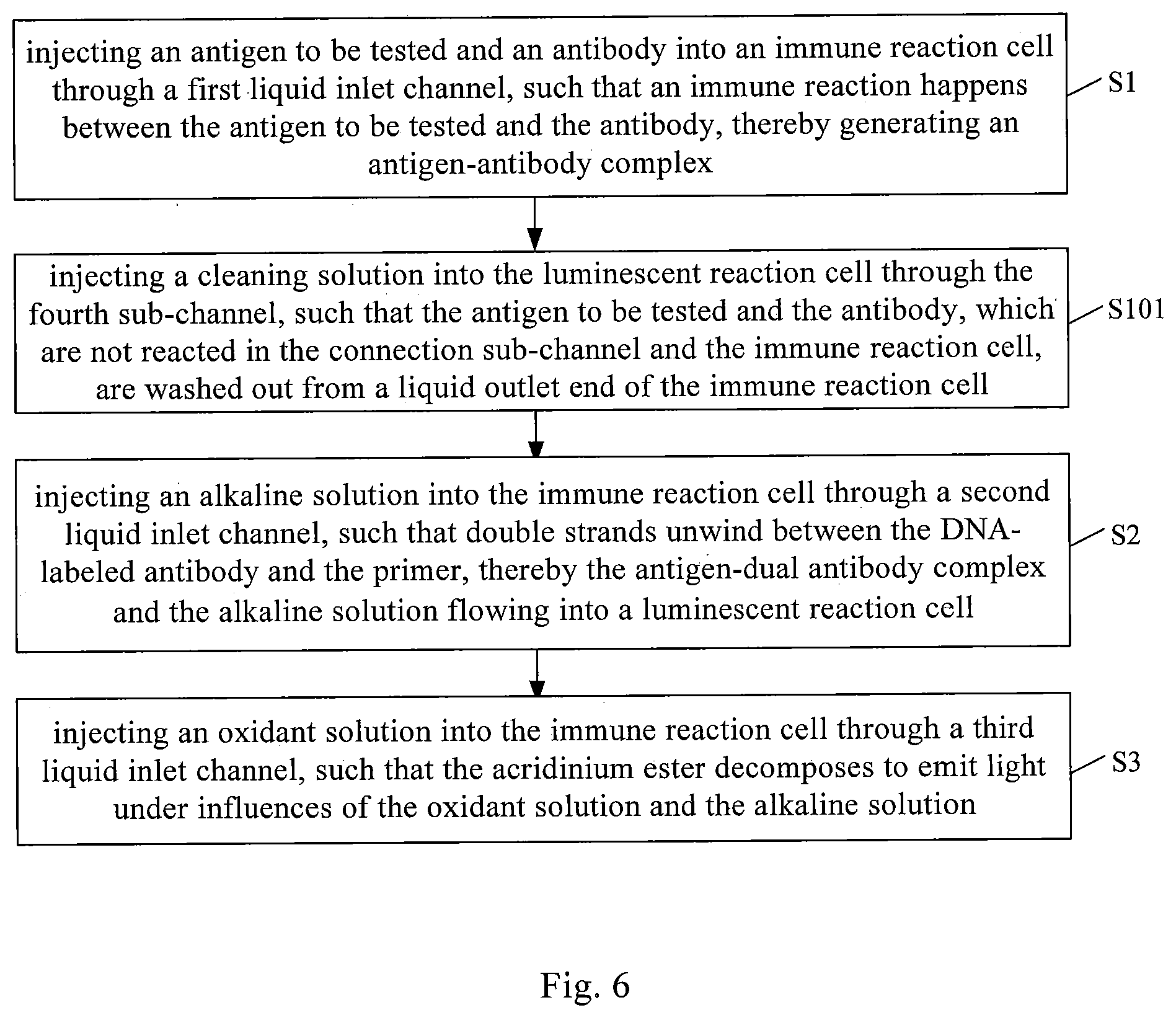
[0079] FIG. 6 is a flow chart of a method for chemiluminescence immunoassay according to another embodiment of the present disclosure. As shown in FIG. 6, the method for chemiluminescence immunoassay is based on the microfluidic chip as described above in any of the above embodiments. Moreover, in the microfluidic chip, the first liquid inlet channel includes a fourth sub-channel. In this case, in addition to the step S1 to the step S3 in the above embodiment, the method for chemiluminescence immunoassay further includes an additional step S101 between the step S1 and the step S2. The step S101 will be described in detail below.
[0080] In step S101, a cleaning solution is injected into the luminescent reaction cell through the fourth sub-channel, so as to wash away the unreacted antigen to be tested and antibodies in the connection sub-channel and the immune reaction cell through the liquid outlet end of the immune reaction cell.
[0081] Optionally, the cleaning solution is deionized water.
[0082] After the end of the immune reaction, and before injecting the alkaline solution into the immune reaction cell through the second liquid inlet channel, the fourth sub-channel is used to inject the deionized water into the immune reaction cell. Thus, the unreacted antigen to be tested and antibodies located in the connection sub - channel and the immune reaction cell are washed away and discharged through the waste liquid outlet. In this way, the unreacted antigen to be tested and antibodies can be effectively prevented from entering the luminescent reaction cell, thereby ensuring the accuracy of subsequent detection results.
[0083] It should be noted that when the immune reaction cell is washed with deionized water, since the antigen-dual antibody complex is immobilized on the primer, the antigen-dual antibody complex can remain in the immune reaction cell, i.e., not being washed away.
[0084] According to the method for chemiluminescence immunoassay provided by an embodiment of the present disclosure, detection of a low amount of reagents can be achieved. It is to be understood that the above embodiments are merely exemplary embodiments employed to illustrate the principle of the present disclosure. However, the present disclosure is not limited to this. Various modifications and improvements can be made by those skilled in the art without departing from the spirit and scope of the present disclosure, and all such modifications and improvements are also considered to fall within the scope of the present disclosure.
* * * * *
D00000
D00001
D00002
D00003
XML
uspto.report is an independent third-party trademark research tool that is not affiliated, endorsed, or sponsored by the United States Patent and Trademark Office (USPTO) or any other governmental organization. The information provided by uspto.report is based on publicly available data at the time of writing and is intended for informational purposes only.
While we strive to provide accurate and up-to-date information, we do not guarantee the accuracy, completeness, reliability, or suitability of the information displayed on this site. The use of this site is at your own risk. Any reliance you place on such information is therefore strictly at your own risk.
All official trademark data, including owner information, should be verified by visiting the official USPTO website at www.uspto.gov. This site is not intended to replace professional legal advice and should not be used as a substitute for consulting with a legal professional who is knowledgeable about trademark law.