Adjustable Angle Tines For Rack
Clerkin; Colin R. ; et al.
U.S. patent application number 16/385001 was filed with the patent office on 2020-10-22 for adjustable angle tines for rack. The applicant listed for this patent is Sub-Zero, Inc.. Invention is credited to William Cesare Cesaroni, Colin R. Clerkin, Curtis Leroy Cruver, IV, Thomas Haft, Joel Andrew Schmidt.
| Application Number | 20200329947 16/385001 |
| Document ID | / |
| Family ID | 1000004022800 |
| Filed Date | 2020-10-22 |


View All Diagrams
| United States Patent Application | 20200329947 |
| Kind Code | A1 |
| Clerkin; Colin R. ; et al. | October 22, 2020 |
ADJUSTABLE ANGLE TINES FOR RACK
Abstract
A dual tine system includes a gear hub including a hub body, right teeth and left teeth, a right gear tooth device mounted to the hub body to rotate the right gear tooth device relative to the gear hub, a left gear tooth device mounted to the hub body to rotate the left gear tooth device relative to the gear hub, a right tine arm, right tines, a left tine arm, and left tines. The right gear tooth device includes a right gear tooth body and a right gear tooth extending from the right gear tooth body to fit within a right valley defined between a pair of the right teeth. The left gear tooth device includes a left gear tooth body and a left gear tooth extending from the left gear tooth body to fit within a left valley defined between a pair of the left teeth.
| Inventors: | Clerkin; Colin R.; (Waunakee, WI) ; Schmidt; Joel Andrew; (Oregon, WI) ; Haft; Thomas; (Madison, WI) ; Cruver, IV; Curtis Leroy; (Elmhurst, IL) ; Cesaroni; William Cesare; (Glenview, IL) | ||||||||||
| Applicant: |
|
||||||||||
|---|---|---|---|---|---|---|---|---|---|---|---|
| Family ID: | 1000004022800 | ||||||||||
| Appl. No.: | 16/385001 | ||||||||||
| Filed: | April 16, 2019 |
| Current U.S. Class: | 1/1 |
| Current CPC Class: | A47L 15/4278 20130101; A47L 15/4225 20130101; A47L 15/50 20130101 |
| International Class: | A47L 15/50 20060101 A47L015/50; A47L 15/42 20060101 A47L015/42 |
Claims
1. A dual tine system for a rack comprising: a gear hub configured to mount to a rack frame, the gear hub comprising a hub body; right teeth that extend from the hub body; and left teeth that extend from the hub body to the left of the right teeth; a right gear tooth device mounted to the hub body to support rotation of the right gear tooth device relative to the gear hub, the right gear tooth device comprising a right gear tooth body; and a right gear tooth that extends from the right gear tooth body, wherein the right gear tooth is configured to fit within a right valley defined between a pair of teeth of the right teeth; a left gear tooth device mounted to the hub body adjacent a left side of the right gear tooth device to support rotation of the left gear tooth device relative to the gear hub, the left gear tooth device comprising a left gear tooth body; and a left gear tooth that extends from the left gear tooth body, wherein the left gear tooth is configured to fit within a left valley defined between a pair of teeth of the left teeth; a right tine arm mounted to the right gear tooth device and configured to mount to the rack frame to rotate with the right gear tooth device and to extend horizontally from the right gear tooth device; a plurality of right tines mounted to the right tine arm, wherein each tine of the plurality of right tines extends from the right tine arm at a first angle; a left tine arm mounted to the left gear tooth device and configured to mount to the rack frame to rotate with the left gear tooth device and to extend horizontally from the left gear tooth device; and a plurality of left tines mounted to the left tine arm, wherein each tine of the plurality of left tines extends from the left tine arm at a second angle.
2. The dual tine system of claim 1, wherein the first angle is equal to the second angle.
3. The dual tine system of claim 1, wherein the first angle is defined relative to a first vector defined parallel to the horizontally extending right tine arm, and wherein the second angle is defined relative to a second vector defined parallel to the horizontally extending left tine arm.
4. The dual tine system of claim 1, wherein the right gear tooth device further comprises a right gear tooth head that extends outward from the right gear tooth body, wherein the left gear tooth device further comprises a left gear tooth head that extends outward from the left gear tooth body, wherein the plurality of right tines and the plurality of left tines align between the right gear tooth head and the left gear tooth head when the plurality of right tines and the plurality of left tines are both in a first position.
5. The dual tine system of claim 4, wherein each tine of the plurality of left tines comprises a connector body that is mounted to the left tine arm, a transition body, and an extension body, wherein the transition body is mounted between the connector body and the extension body to change a first distance of the extension body relative to a second distance of the connector body, wherein the first distance and the second distance are defined relative to a plane defined parallel to and including a center of the horizontally extending left tine arm.
6. The dual tine system of claim 4, wherein the right gear tooth head has a concave contact face that faces away from the right tine arm.
7. The dual tine system of claim 1, wherein successive tines of the plurality of right tines are separated by a first distance, wherein successive tines of the plurality of left tines are separated by a second distance, wherein the first distance is equal to the second distance.
8. The dual tine system of claim 7, wherein a first right tine distance is different from a first left tine distance, wherein the first right tine distance is defined as a distance between a first tine of the right plurality of tines that is closest to a first end of the right tine arm that is mounted to the right gear tooth device, wherein the first left tine distance is defined as a distance between a first tine of the left plurality of tines that is closest to a first end of the left tine arm that is mounted to the left gear tooth device.
9. The dual tine system of claim 8, wherein a difference between the first right tine distance and the first left tine distance is half the first distance.
10. The dual tine system of claim 1, wherein the right gear tooth device further comprises a gear tooth tine aperture wall formed in the left gear tooth body, wherein the right tine arm includes a mounting head, wherein the mounting head is inserted in the gear tooth tine aperture wall to mount the right tine arm to the right gear tooth device.
11. The dual tine system of claim 1, wherein the right gear tooth device further comprises a gear tooth connector body mounted to a bottom of the right gear tooth body.
12. The dual tine system of claim 11, wherein the right gear tooth device further comprises a gear tooth tine aperture wall formed in the gear tooth connector body, wherein the right tine arm includes a mounting head, wherein the mounting head is inserted in the gear tooth tine aperture wall to mount the right tine arm to the right gear tooth device.
13. The dual tine system of claim 12, wherein the right gear tooth device further comprises a mounting prong that extends from the gear tooth connector body in a direction opposite the right tine arm.
14. The dual tine system of claim 13, wherein the gear hub further comprises an aperture wall formed in the hub body, wherein the mounting prong is inserted in the aperture wall to mount the right gear tooth device to the gear hub.
15. The dual tine system of claim 14, wherein the right teeth are arranged to have an approximately equal distance from a vector through a center of the aperture wall and parallel to an insertion direction of the mounting prong into the aperture wall.
16. The dual tine system of claim 11, wherein the right gear tooth body is configured to be deflectable in a direction away from the right teeth relative to the gear tooth connector body to release the right gear tooth from the right valley defined between the pair of teeth of the right teeth.
17. The dual tine system of claim 16, wherein the right gear tooth device further comprises a gear tooth stop that extends upward from the gear tooth connector body, wherein the gear tooth stop is configured to stop a deflection of the right gear tooth body when a maximum deflection in the direction away from the right teeth is reached.
18. The dual tine system of claim 1, wherein a number of teeth of the right teeth is equal to a number of teeth of the left teeth and is greater than two.
19. A rack comprising: a rack frame; a gear hub mounted to the rack frame, the gear hub comprising a hub body; right teeth that extend from the hub body; and left teeth that extend from the hub body to the left of the right teeth; a right gear tooth device mounted to the hub body to support rotation of the right gear tooth device relative to the gear hub, the right gear tooth device comprising a right gear tooth body; and a right gear tooth that extends from the right gear tooth body, wherein the right gear tooth is configured to fit within a right valley defined between a pair of teeth of the right teeth; a left gear tooth device mounted to the hub body adjacent a left side of the right gear tooth device to support rotation of the left gear tooth device relative to the gear hub, the left gear tooth device comprising a left gear tooth body; and a left gear tooth that extends from the left gear tooth body, wherein the left gear tooth is configured to fit within a left valley defined between a pair of teeth of the left teeth; a right tine arm mounted to the right gear tooth device and to the rack frame to rotate with the right gear tooth device and to extend horizontally from the right gear tooth device; a plurality of right tines mounted to the right tine arm, wherein each tine of the plurality of right tines extends from the right tine arm at a first angle; a left tine arm mounted to the left gear tooth device and to the rack frame to rotate with the left gear tooth device and to extend horizontally from the left gear tooth device; and a plurality of left tines mounted to the left tine arm, wherein each tine of the plurality of left tines extends from the left tine arm at a second angle.
20. A dishwasher comprising: a body; a tub bottom wall mounted within the body; a door; a hinge pivotally mounting the door to the body; a rack mounted within the body above the tub bottom wall and configured to hold dishware, the rack comprising a rack frame; and a sliding mechanism mounted to the rack frame and configured to provide movement of the rack relative to the body; a fluid supply system mounted to the body and comprising a wash pump; a conduit mounted to the wash pump; and a spray arm configured to mount to the conduit to receive liquid from the wash pump, the spray arm comprising a hole through which the liquid received from the wash pump is sprayed when the dishwasher is used; and a gear hub mounted to the rack frame, the gear hub comprising a hub body; right teeth that extend from the hub body; and left teeth that extend from the hub body to the left of the right teeth; a right gear tooth device mounted to the hub body to support rotation of the right gear tooth device relative to the gear hub, the right gear tooth device comprising a right gear tooth body; and a right gear tooth that extends from the right gear tooth body, wherein the right gear tooth is configured to fit within a right valley defined between a pair of teeth of the right teeth; a left gear tooth device mounted to the hub body adjacent a left side of the right gear tooth device to support rotation of the left gear tooth device relative to the gear hub, the left gear tooth device comprising a left gear tooth body; and a left gear tooth that extends from the left gear tooth body, wherein the left gear tooth is configured to fit within a left valley defined between a pair of teeth of the left teeth; a right tine arm mounted to the right gear tooth device and to the rack frame to rotate with the right gear tooth device and to extend horizontally from the right gear tooth device; a plurality of right tines mounted to the right tine arm, wherein each tine of the plurality of right tines extends from the right tine arm at a first angle; a left tine arm mounted to the left gear tooth device and to the rack frame to rotate with the left gear tooth device and to extend horizontally from the left gear tooth device; and a plurality of left tines mounted to the left tine arm, wherein each tine of the plurality of left tines extends from the left tine arm at a second angle.
Description
BACKGROUND
[0001] Dishwashers are provided with an interior wash chamber or tub into which one or more racks or baskets are designed to hold dishware within the interior of the tub during operation of the dishwasher. A plurality of tines are positioned within the rack to support various dishware for optimum cleaning and to provide a separation between dishware items such as glasses, plates, and bowls to avoid breakage. Some tines are mounted to tine arms that can be rotated to a fully upright position or to a fully down position to facilitate positioning of dishware items for cleaning. Nevertheless, it remains difficult to adequately support odd sized dishware for optimal cleaning and breakage avoidance.
SUMMARY
[0002] In an example embodiment, a dual tine system for a rack is provided. The dual tine system includes, but is not limited to, a gear hub, a right gear tooth device, a left gear tooth device, a right tine arm, a plurality of right tines, a left tine arm, and a plurality of left tines. The gear hub is configured to mount to a rack frame. The gear hub includes, but is not limited to, a hub body, right teeth that extend from the hub body, and left teeth that extend from the hub body to the left of the right teeth. The right gear tooth device is mounted to the hub body to support rotation of the right gear tooth device relative to the gear hub. The right gear tooth device includes, but is not limited to, a right gear tooth body, and a right gear tooth that extends from the right gear tooth body. The right gear tooth is configured to fit within a right valley defined between a pair of teeth of the right teeth. The left gear tooth device is mounted to the hub body adjacent a left side of the right gear tooth device to support rotation of the left gear tooth device relative to the gear hub. The left gear tooth device includes, but is not limited to, a left gear tooth body, and a left gear tooth that extends from the left gear tooth body. The left gear tooth is configured to fit within a left valley defined between a pair of teeth of the left teeth. The right tine arm is mounted to the right gear tooth device and to the rack frame to rotate with the right gear tooth device and to extend horizontally from the right gear tooth device. The plurality of right tines is mounted to the right tine arm. Each tine of the plurality of right tines extends from the right tine arm at a first angle. The left tine arm is mounted to the left gear tooth device and to the rack frame to rotate with the left gear tooth device and to extend horizontally from the left gear tooth device. The plurality of left tines is mounted to the left tine arm. Each tine of the plurality of left tines extends from the left tine arm at a second angle.
[0003] In another example embodiment, a rack for a dishwasher is provided. The rack includes, but is not limited to, a rack frame and the gear hub mounted to the rack frame.
[0004] In yet another example embodiment, a dishwasher is provided. The dishwasher includes, but is not limited to, a body, a tub bottom wall mounted within the body, a door, a hinge pivotally mounting the door to the body, a rack, a fluid supply system mounted to the body, and the gear hub. The rack is mounted within the body above the tub bottom wall and configured to hold dishware. The rack includes, but is not limited to, a rack frame and a sliding mechanism mounted to the rack frame to provide movement of the rack relative to the body. The gear hub is mounted to the rack frame. The fluid supply system is mounted to the body and includes, but is not limited to, a wash pump, a conduit mounted to the wash pump, and a spray arm configured to mount to the conduit to receive liquid from the wash pump. The spray arm comprising a hole through which the liquid received from the wash pump is sprayed when the dishwasher is used.
[0005] Other principal features and advantages will become apparent to those skilled in the art upon review of the following drawings, the detailed description, and the appended claims.
BRIEF DESCRIPTION OF THE DRAWINGS
[0006] Illustrative embodiments of the disclosed subject matter will hereafter be described with reference to the accompanying drawings, wherein like numerals denote like elements.
[0007] FIG. 1 depicts a front perspective view of a dishwasher in accordance with an illustrative embodiment.
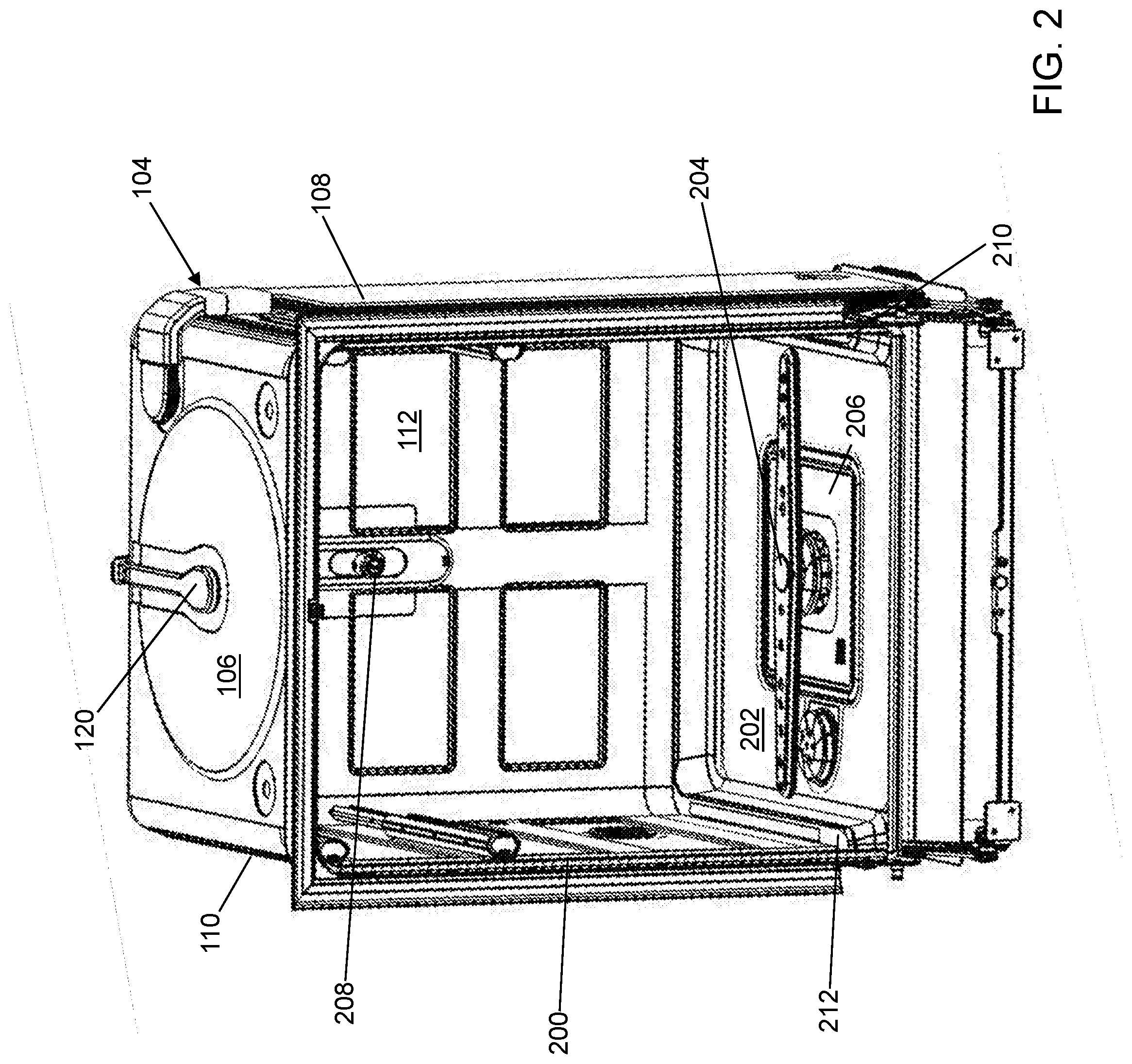
[0008] FIG. 2 depicts a front view of the dishwasher of FIG. 1 without a door or dishware racks in accordance with an illustrative embodiment.
[0009] FIG. 3 depicts a front perspective view of the dishwasher tub of the dishwasher of FIG. 1 in accordance with an illustrative embodiment.
[0010] FIG. 4 depicts a front perspective view of a bottom dishware rack of the dishwasher of FIG. 1 in accordance with an illustrative embodiment.
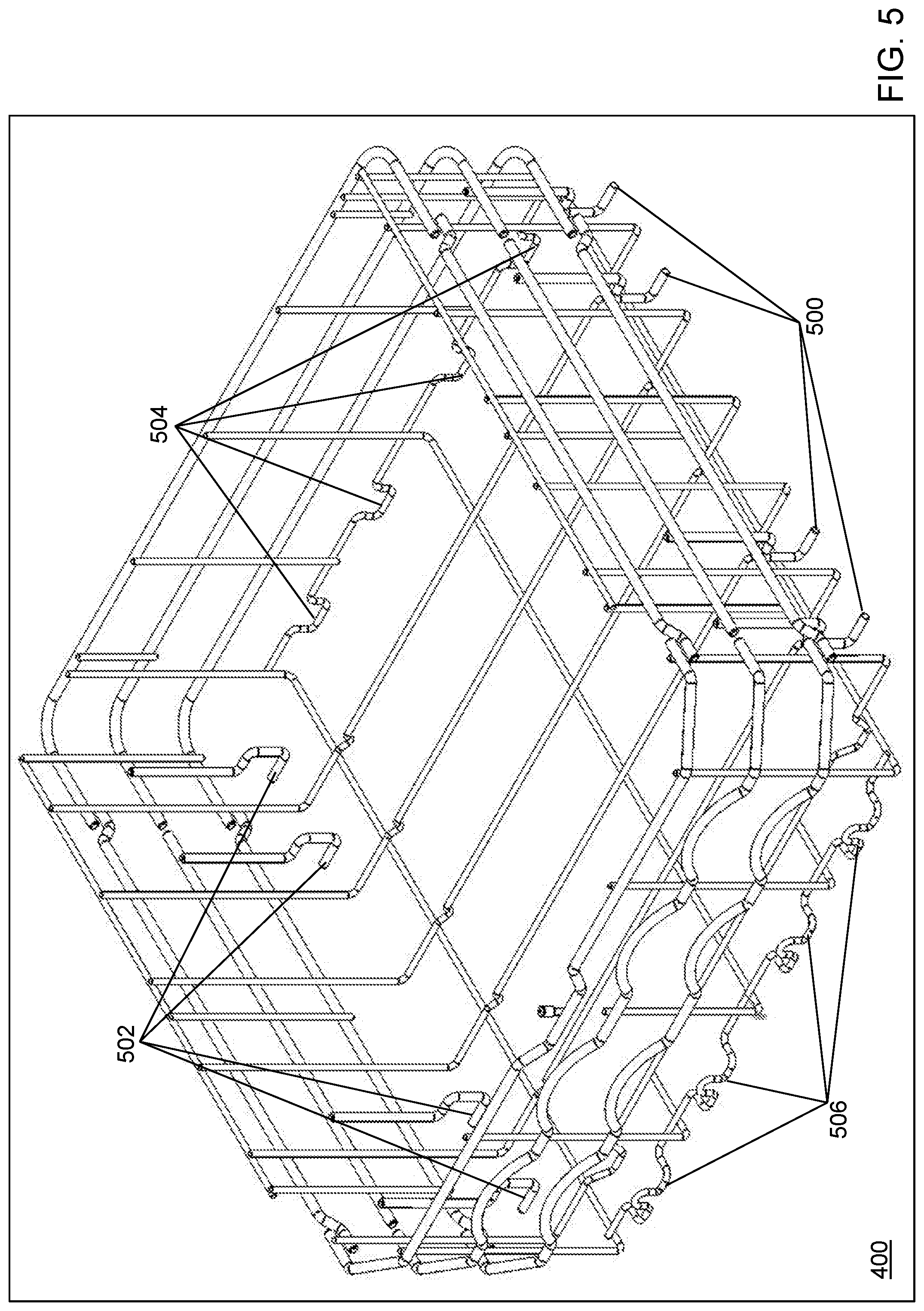
[0011] FIG. 5 depicts a front perspective view of a rack frame of the bottom dishware rack of FIG. 4 in accordance with an illustrative embodiment.
[0012] FIG. 6 depicts a front view of the bottom dishware rack of FIG. 4 in accordance with an illustrative embodiment.
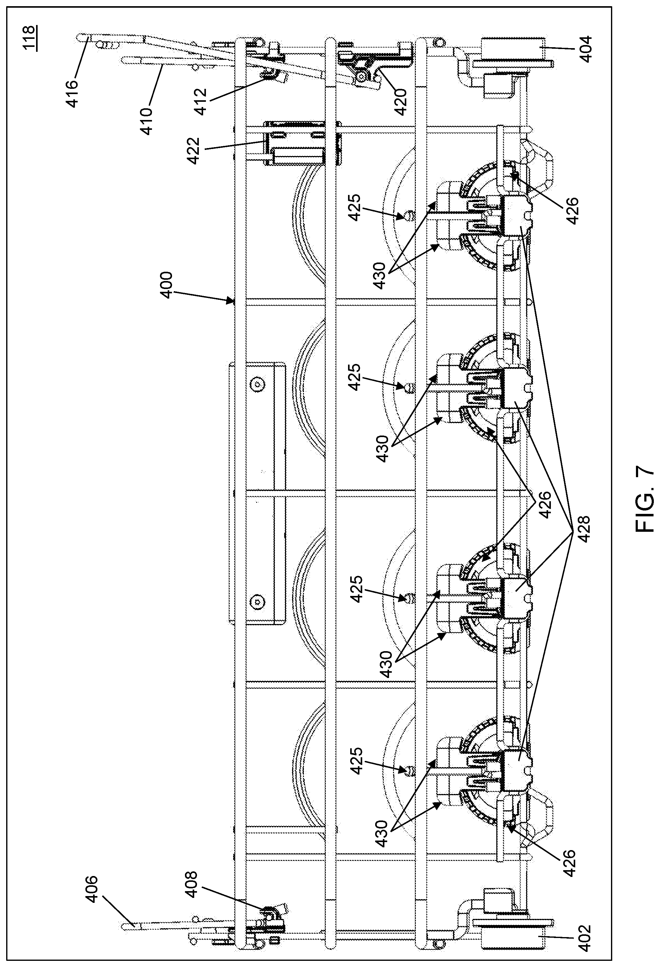
[0013] FIG. 7 depicts a back view of the bottom dishware rack of FIG. 4 in accordance with an illustrative embodiment.
[0014] FIG. 8 depicts a left side view of the bottom dishware rack of FIG. 4 in accordance with an illustrative embodiment.
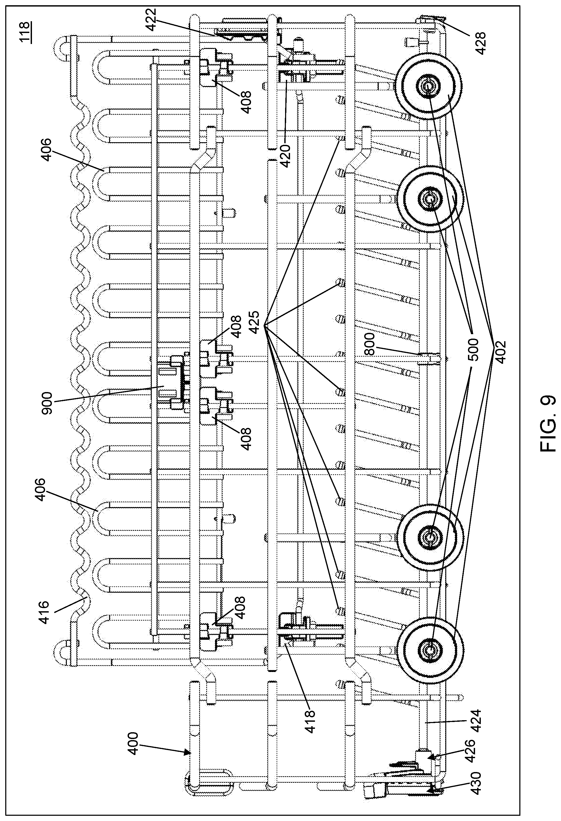
[0015] FIG. 9 depicts a right side view of the bottom dishware rack of FIG. 4 in accordance with an illustrative embodiment.
[0016] FIG. 10 depicts a top view of the bottom dishware rack of FIG. 4 in accordance with an illustrative embodiment.
[0017] FIG. 11 depicts a zoomed right side view of a left side of the bottom dishware rack of FIG. 4 in accordance with an illustrative embodiment.
[0018] FIG. 12 depicts a front, right side perspective view of a gear hub of a gear hub of the bottom dishware rack of FIG. 4 in accordance with an illustrative embodiment.
[0019] FIG. 13 depicts a back, bottom perspective view of the gear hub of FIG. 12 in accordance with an illustrative embodiment.
[0020] FIG. 14 depicts a back perspective view of a right gear tooth device of the bottom dishware rack of FIG. 4 in accordance with an illustrative embodiment.
[0021] FIG. 15 depicts a front right perspective view of the right gear tooth device of FIG. 14 in accordance with an illustrative embodiment.
[0022] FIG. 16 depicts a front left perspective view of the right gear tooth device of FIG. 14 in accordance with an illustrative embodiment.
[0023] FIG. 17 depicts a front right perspective view of a left gear tooth device of the bottom dishware rack of FIG. 4 in accordance with an illustrative embodiment.
[0024] FIG. 18 depicts a right side view of a tine arm of the bottom dishware rack of FIG. 4 in an upright position in accordance with an illustrative embodiment.
[0025] FIG. 19 depicts a front right perspective view of the tine arm of FIG. 18 in accordance with an illustrative embodiment.
[0026] FIG. 20 depicts a front view of a right tine of the bottom dishware rack of FIG. 4 in an upright position in accordance with an illustrative embodiment.
[0027] FIG. 21 depicts a front view of a left tine in accordance with an illustrative embodiment.
[0028] FIG. 22 depicts a front view of the left tine of FIG. 21 rotated 90 degrees in a counterclockwise direction to a down position in accordance with an illustrative embodiment.
[0029] FIG. 23 depicts a front view of the left tine of FIG. 21 rotated approximately 45 degrees in a counterclockwise direction to a down position in accordance with an illustrative embodiment.
[0030] FIG. 24 depicts a back, bottom perspective view of a hub system of the bottom dishware rack of FIG. 4 in accordance with an illustrative embodiment.
[0031] FIG. 25 depicts a front view of the bottom dishware rack of FIG. 4 with two hub systems rotated to accommodate a large bowl in accordance with an illustrative embodiment.
[0032] FIG. 26 depicts a front perspective view of the tines of the bottom dishware rack of FIG. 4 with the two hub systems rotated to accommodate the large bowl in accordance with an illustrative embodiment.
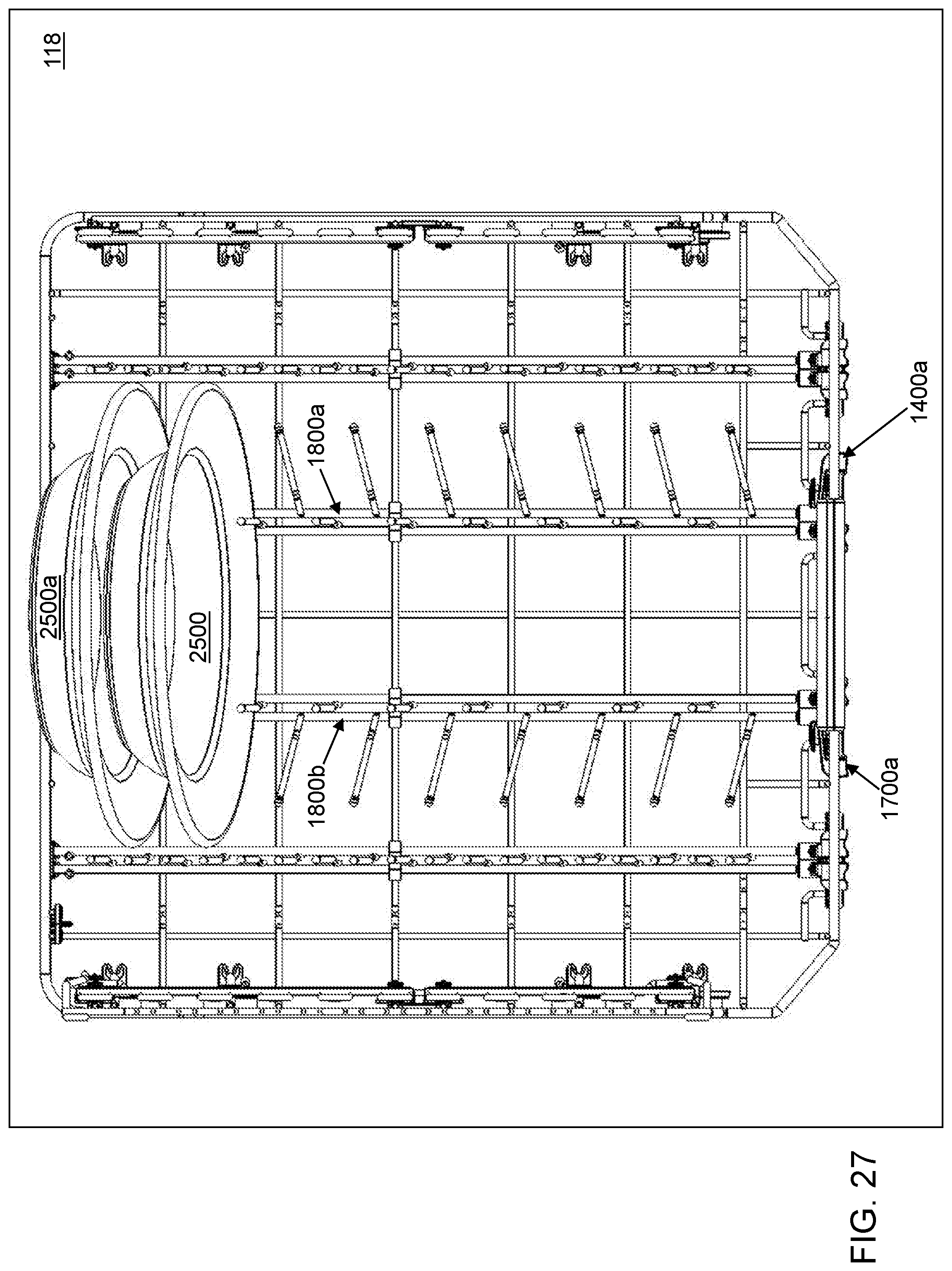
[0033] FIG. 27 depicts a top view of the bottom dishware rack of FIG. 4 with the two hub systems rotated to accommodate the large bowl of FIG. 25 in accordance with an illustrative embodiment.
[0034] FIG. 28 depicts a front view of the bottom dishware rack of FIG. 4 with two hub systems rotated to accommodate a deep bowl in accordance with an illustrative embodiment.
[0035] FIG. 29 depicts a top view of the bottom dishware rack of FIG. 4 with the two hub systems rotated to accommodate the deep bowl of FIG. 28 in accordance with an illustrative embodiment.
[0036] FIG. 30 depicts a top perspective view of the bottom dishware rack of FIG. 4 with the two hub systems rotated to accommodate the deep bowl of FIG. 28 in accordance with an illustrative embodiment.
[0037] FIG. 31 depicts a front perspective view of the bottom dishware rack of FIG. 4 with one hub system rotated to accommodate a large wine glass in accordance with an illustrative embodiment.
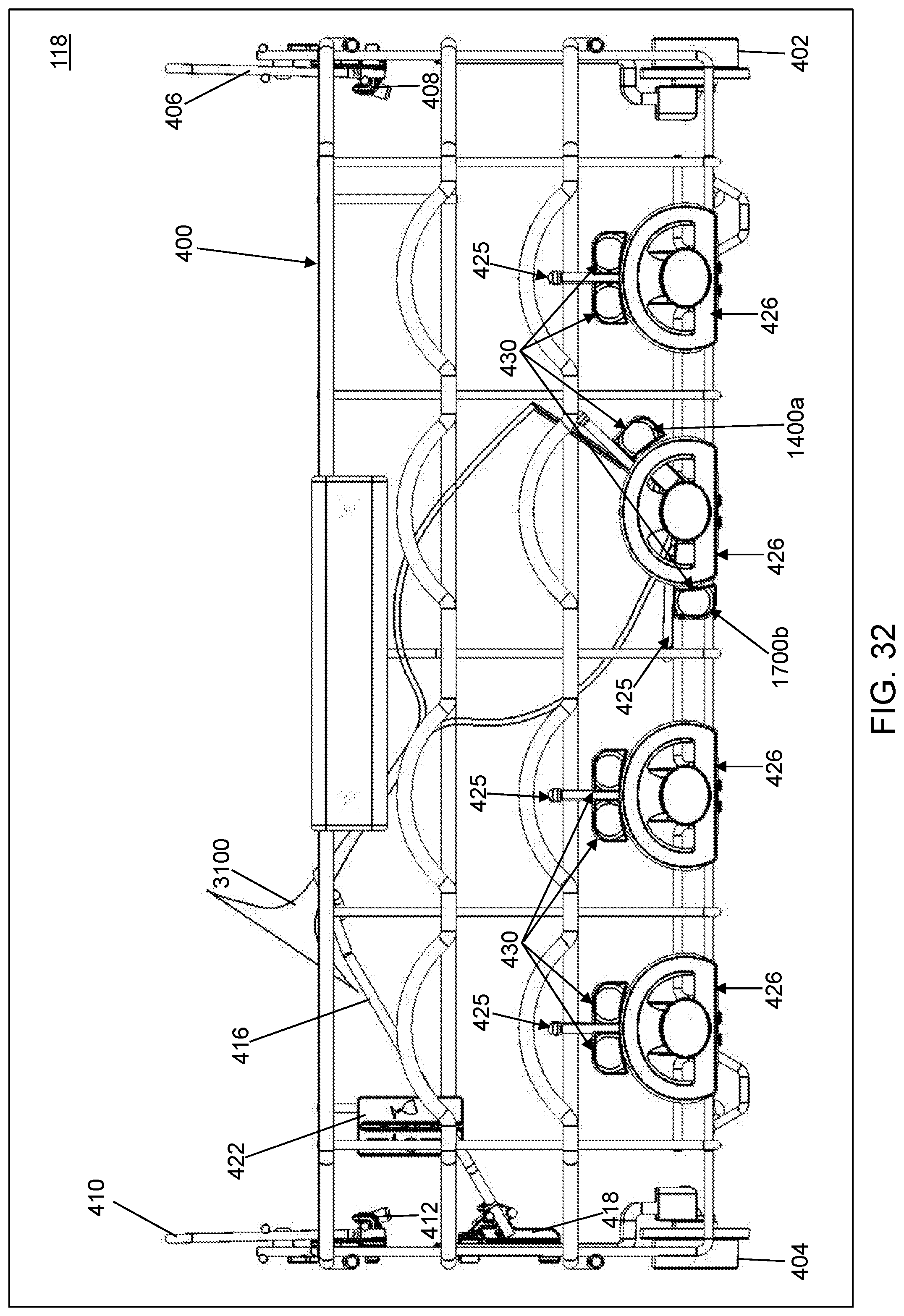
[0038] FIG. 32 depicts a front view of the bottom dishware rack of FIG. 4 with the one hub system rotated to accommodate the large wine glass in accordance with an illustrative embodiment.
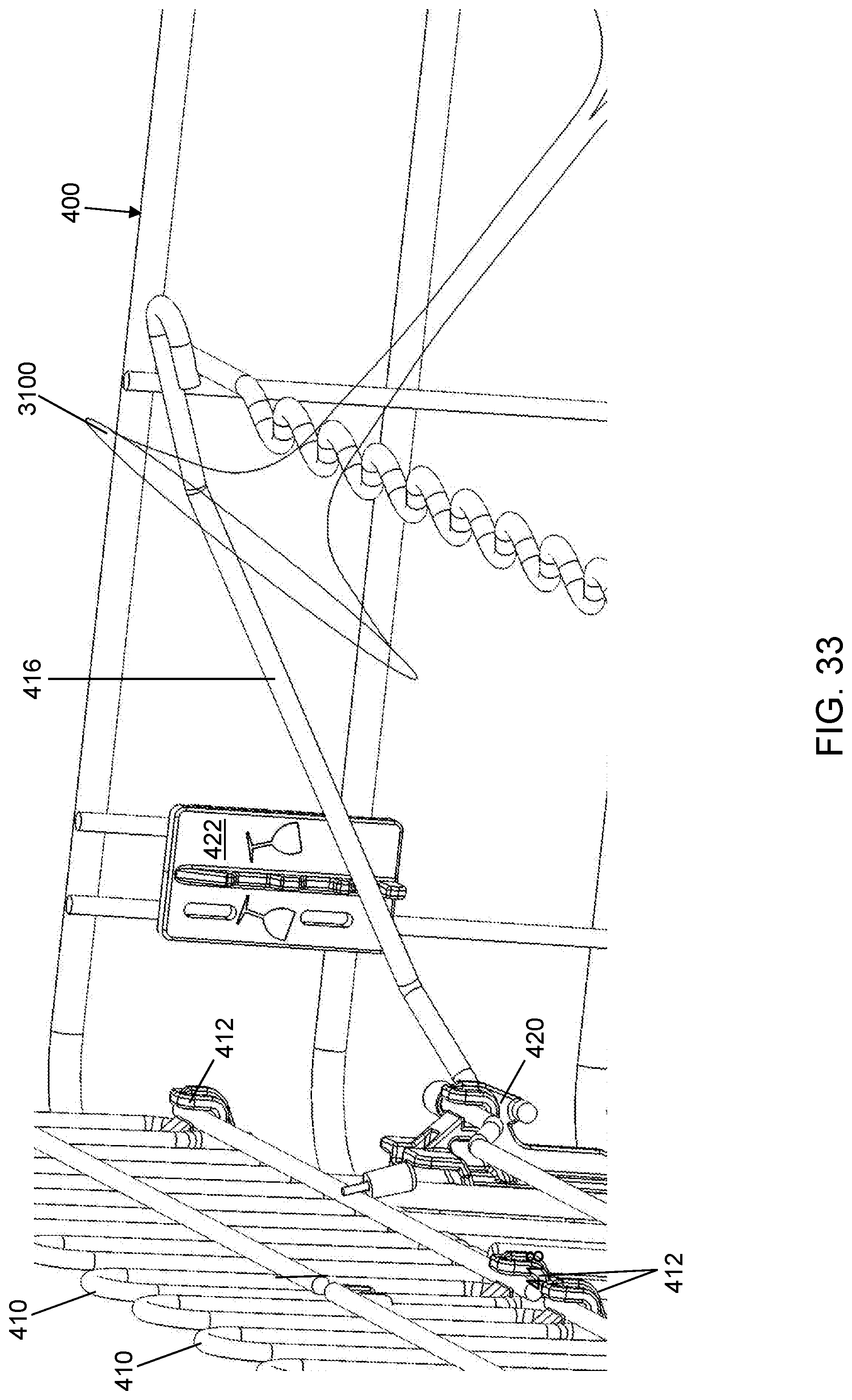
[0039] FIG. 33 depicts a zoomed front perspective view of a support arm of the bottom dishware rack of FIG. 4 rotated to accommodate the large wine glass in accordance with an illustrative embodiment.
[0040] FIG. 34 depicts a right side perspective view of the support arm of the bottom dishware rack of FIG. 4 in accordance with an illustrative embodiment.
[0041] FIG. 35 depicts a left side perspective view of a support arm socket device of the bottom dishware rack of FIG. 4 in accordance with an illustrative embodiment.
[0042] FIG. 36 depicts a top, right side perspective view of the support arm socket device of FIG. 35 in accordance with an illustrative embodiment.
[0043] FIG. 37 depicts a back perspective view of the support arm of FIG. 34 engaged in a first position with the support arm socket device of FIG. 35 in accordance with an illustrative embodiment.
[0044] FIG. 38 depicts a right side perspective view of the support arm of FIG. 34 engaged in the first position with the support arm socket device of FIG. 35 in accordance with an illustrative embodiment.
[0045] FIG. 39 depicts a back, right side perspective view of the support arm of FIG. 34 engaged in a second position with the support arm socket device of FIG. 35 in accordance with an illustrative embodiment.
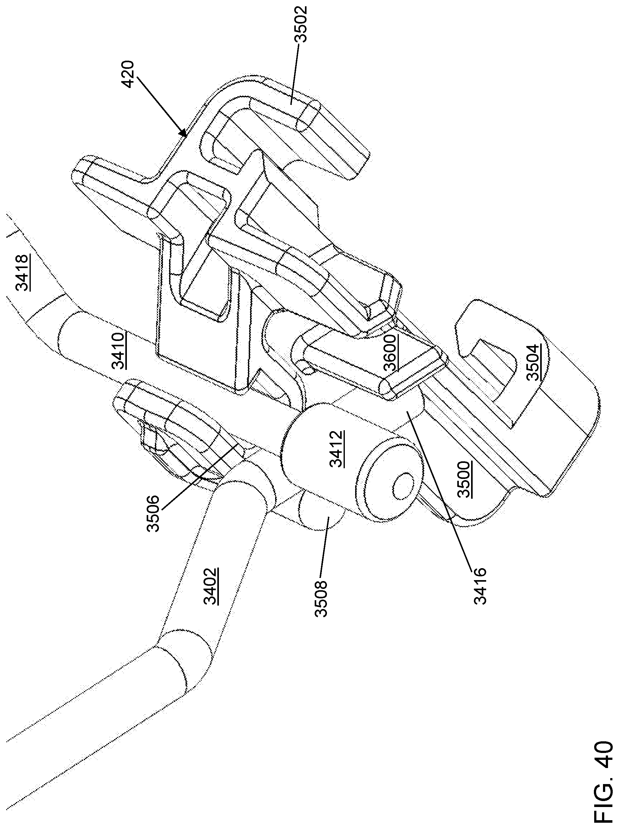
[0046] FIG. 40 depicts a back, top perspective view of the support arm of FIG. 34 engaged in the second position with the support arm socket device of FIG. 35 in accordance with an illustrative embodiment.
[0047] FIG. 41 depicts a front perspective view of a support arm engagement device of the bottom dishware rack of FIG. 4 in accordance with an illustrative embodiment.
[0048] FIG. 42 depicts a back left side perspective view of the support arm engagement device of FIG. 41 in accordance with an illustrative embodiment.
[0049] FIG. 43 depicts a right side perspective view of the support arm engagement device of FIG. 41 in accordance with an illustrative embodiment.
[0050] FIG. 44 depicts a back perspective view of the support arm engagement device of FIG. 41 in accordance with an illustrative embodiment.
[0051] FIG. 45 depicts a back view of the support arm of FIG. 34 engaged in the second position with the support arm socket device of FIG. 35 and in a second position with the support arm engagement device of FIG. 41 in accordance with an illustrative embodiment.
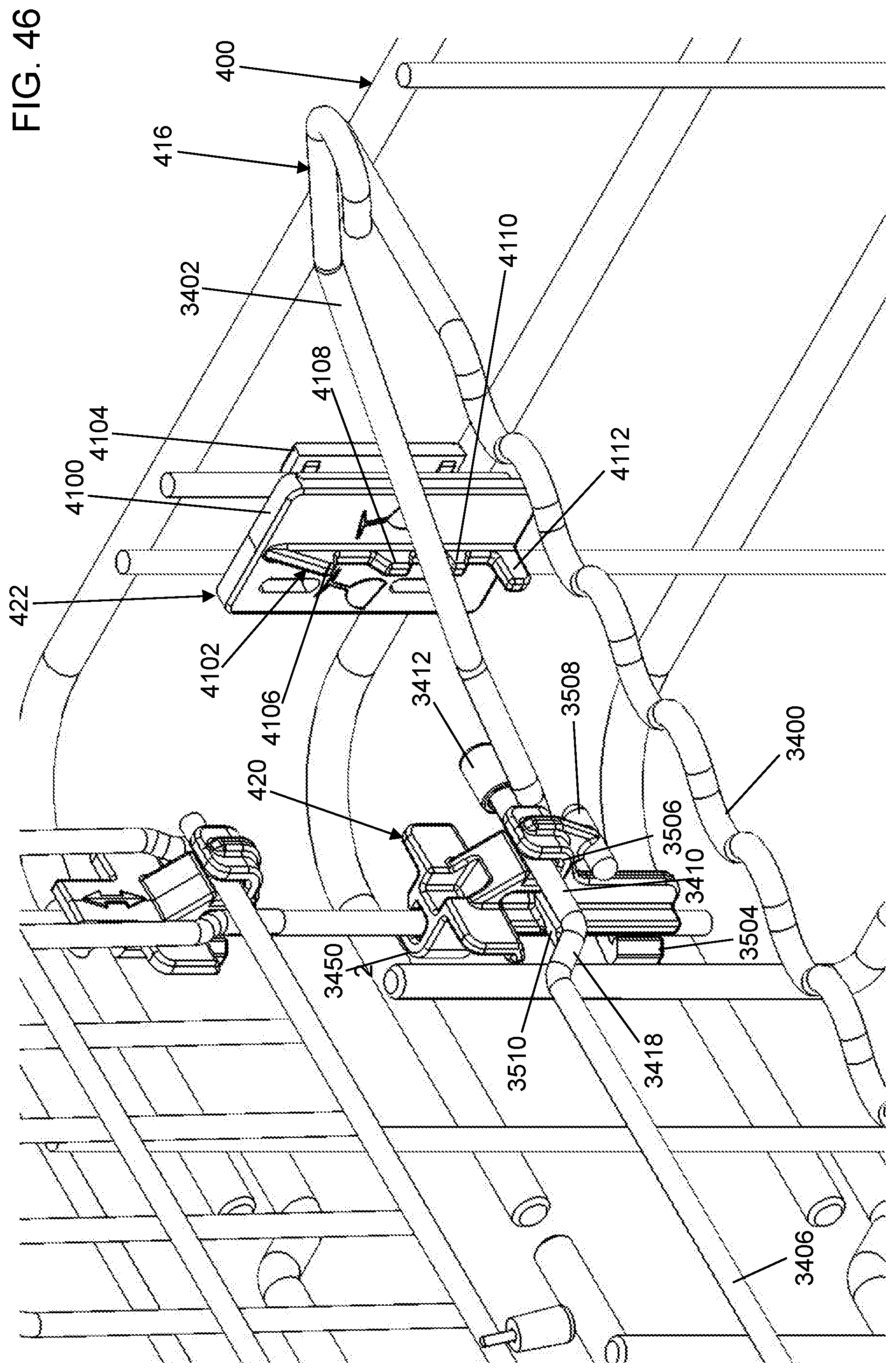
[0052] FIG. 46 depicts a front, right side view of the support arm of FIG. 34 engaged in the second position with the support arm engagement device of FIG. 41 in accordance with an illustrative embodiment.
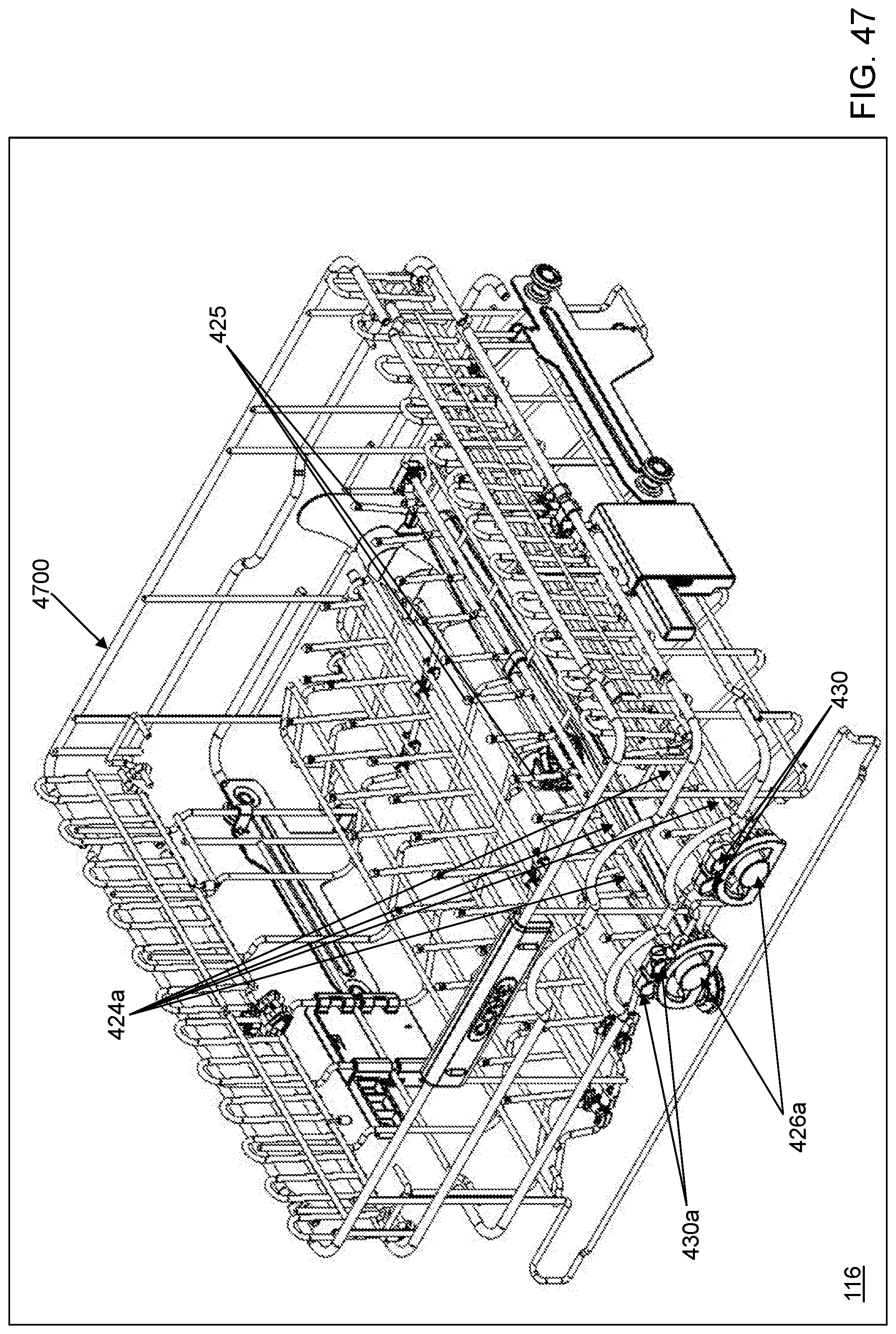
[0053] FIG. 47 depicts a front perspective view of a top rack of the dishwasher of FIG. 1 in accordance with an illustrative embodiment.
DETAILED DESCRIPTION
[0054] Referring to FIG. 1, a dishwasher 100 is shown in accordance with an illustrative embodiment. Dishwasher 100 may include a door 102 and a body 104. In the illustrative embodiment, body 104 includes a plurality of walls that, in combination with door 102, form an enclosed space or wash tub 200 (shown with reference to FIG. 2). The plurality of walls of body 104 may include a top wall 106, a right side wall 108, a left side wall 110, a back wall 112, and a bottom wall 114. Top wall 106, right side wall 108, left side wall 110, back wall 112, and a tub bottom wall 202 (shown with reference to FIG. 2) define wash tub 200. Bottom wall 114 may not cover the entire area between right side wall 108, left side wall 110, and back wall 112. A wall may include a plurality of walls such as an interior wall that is distinct from an exterior wall but together provide a barrier between wash tub 200 and the exterior of dishwasher 100. Items such as insulation, wires, piping, electronics, one or more pumps, a heating element, etc. may be mounted within one or more of the walls.
[0055] Door 102 rotates from a vertical position to a horizontal position as understood by a person of skill in the art though door 102 may rotate in other directions in alternative embodiments. A plurality of hinges such as a right hinge 122 pivotally mount door 102 to body 104 proximate a lower edge of door 102. In the illustrative embodiment, door 102 rotates downward to provide access to wash tub 200. In an alternative embodiment, dishwasher 100 may be implemented as a drawer type dishwasher in which door 110 slides out from body 104.
[0056] Wash tub 200 may include one or more racks on which dishware or other items are placed for washing and/or rinsing. For example, dishwasher 100 includes a top dishware rack 116 and a bottom dishware rack 118. Dishwasher 100 may include one or more additional racks above and/or below top dishware rack 116 and/or bottom dishware rack 118. For example, a third rack 312 (shown referring to FIG. 3) may be positioned above top dishware rack 116. As understood by a person of skill in the art, top dishware rack 116, bottom dishware rack 118 and third rack 312 may be slid into and out of wash tub 200 using a variety of mounting methods. A height of top dishware rack 116 and/or bottom dishware rack 118 within body 104 and relative to tub bottom wall 202 may be adjustable.
[0057] Wash tub 200 may include one or more spray arms that spray a washing fluid on the dishware loaded on the one or more racks. For example, dishwasher 100 may include a lower spray arm 204, an upper spray arm 300 (shown referring to FIG. 3), and a middle spray arm 302 (shown referring to FIG. 3) mounted at different heights above tub bottom wall 202. A top spray arm conduit 120 may mount upper spray arm 300 to a wash pump 304 (shown with reference to FIG. 3). Upper spray arm 300 may be mounted to extend down from an inner surface of top wall 106 and may be configured to spray the washing fluid upward and/or downward as understood by a person of skill in the art. Lower spray arm 204 may be mounted to extend up from tub bottom wall 202 and may be configured to spray the washing fluid upward and/or downward as understood by a person of skill in the art. Middle spray arm 302 may be mounted to a bottom of top dishware rack 116 and may be configured to spray the washing fluid upward and/or downward as understood by a person of skill in the art. Though not shown, various conduits may connect wash pump 304 to lower spray arm 204 and to middle spray arm 302. For example, a middle spray arm nozzle 208 (shown with reference to FIG. 2) may provide fluid from wash pump 304 to middle spray arm 302. Dishwasher 100 may include a fewer or a greater number of spray arms.
[0058] Use of directional terms, such as top, bottom, right, left, front, back, upper, lower, etc. are merely intended to facilitate reference to the various surfaces of the described structures relative to the orientations shown in the drawings and are not intended to be limiting in any manner. For example, front is with reference to a front of dishwasher 100 as defined by a location of door 102.
[0059] As used herein, the term "mount" includes join, unite, connect, couple, associate, insert, hang, hold, affix, attach, fasten, bind, paste, secure, bolt, screw, rivet, solder, weld, glue, form over, form in, layer, mold, rest on, rest against, abut, and other like terms. The phrases "mounted on", "mounted to", and equivalent phrases indicate any interior or exterior portion of the element referenced. These phrases also encompass direct mounting (in which the referenced elements are in direct contact) and indirect mounting (in which the referenced elements are not in direct contact, but are connected through an intermediate element). Elements referenced as mounted to each other herein may further be integrally formed together, for example, using a molding or thermoforming process as understood by a person of skill in the art. As a result, elements described herein as being mounted to each other need not be discrete structural elements. The elements may be mounted permanently, removably, or releasably unless specified otherwise.
[0060] Dishwasher 100 may include a greater or a fewer number of components than those illustrated. The one or more components of dishwasher 100 may be formed of one or more materials, such as various metals, glass, elastomeric material, and/or plastics having a sufficient strength and rigidity to support the described application.
[0061] Referring to FIG. 2, a front view of dishwasher 100 is shown in accordance with an illustrative embodiment without door 102, top dishware rack 116, or bottom dishware rack 118. Tub bottom wall 202 mounts within body 104 between right side wall 108, left side wall 110, and back wall 112 and above bottom wall 114. A sump screen 206 mounts to tub bottom wall 202 above a sump 310 (shown with reference to FIG. 3) and is configured to allow fluid to flow downward out of wash tub 200.
[0062] Referring to FIG. 3, a front view of a body 104 of dishwasher 100 is shown in accordance with an illustrative embodiment. In the illustrative embodiment, top dishware rack 116 can be slid in and out of dishwasher 100 using a right side rail 306 mounted to an interior of right side wall 108 and a left side rail 308 mounted to an interior of left side wall 110. Additionally, a height of top dishware rack 116 within body 104 and relative to tub bottom wall 202 is adjustable. Thus, top dishware rack 116 may be moved up and down along back wall 112 with middle spray arm nozzle 208. As understood by a person of skill in the art, the fluid that is sprayed out of lower spray arm 204, upper spray arm 300, and/or middle spray arm 302 may be collected in sump 310 that forms a reservoir at a bottom of tub bottom wall 202 and, if desired, filtered and recirculated by a fluid supply system using pump 304. Controls for selection of and operation of a cleaning cycle may be mounted to or within door 102 and/or distributed in other locations of dishwasher 100. Top dishware rack 116, bottom dishware rack 118, and third rack 312 may be moved in and out of body 104 relative to wash tub 200 using a variety of structural sliding mechanisms such as wheels, brackets, rails, etc.
[0063] Referring to FIG. 4, a front perspective view of bottom dishware rack 118 of dishwasher 100 is shown in accordance with an illustrative embodiment. Referring to FIG. 5, a front perspective view of rack frame 400 of bottom dishware rack 118 is shown in accordance with an illustrative embodiment. Referring to FIG. 6, a front view of bottom dishware rack 118 is shown in accordance with an illustrative embodiment. Referring to FIG. 7, a back view of bottom dishware rack 118 is shown in accordance with an illustrative embodiment. Referring to FIG. 8, a left side view of bottom dishware rack 118 is shown in accordance with an illustrative embodiment. Referring to FIG. 9, a right side view of bottom dishware rack 118 is shown in accordance with an illustrative embodiment. Referring to FIG. 10, a top view of bottom dishware rack 118 is shown in accordance with an illustrative embodiment. Referring to FIG. 11, a zoomed right side view of a left side of bottom dishware rack 118 is shown in accordance with an illustrative embodiment.
[0064] In the illustrative embodiment, bottom dishware rack 118 includes a bottom rack frame 400, a right plurality of wheels 402, and a left plurality of wheels 404. Rack frame 400 includes a plurality of stacked coated wires that generally form a rectangular shape though other shapes may be formed. Rack frame 400 is configured to fit within wash tub 200 and to hold dishware for cleaning. Rack frame 400 is configured to provide a generally free flow of water in and around the plurality of stacked coated wires that form rack frame 400. The right plurality of wheels 402 and the left plurality of wheels 404 are mounted to a right side and a left side, respectively, of rack frame 400 to allow bottom dishware rack 118 to be slid in and out of dishwasher 100, for example, on a right platform 210 (shown referring to FIG. 2) and a left platform 212 above tub bottom wall 202 (shown referring to FIG. 2). The right plurality of wheels 402 and the left plurality of wheels 404 may include a greater or a fewer number of wheels.
[0065] The plurality of stacked coated wires may be curved to form a right plurality of wheel axles 500, a left plurality of wheel axles 502, a plurality of tine support cups 504, and a plurality of hub support cups 506 to which the right plurality of wheels 402, the left plurality of wheels 404, a plurality of tine socket devices 428, and a plurality of tine gear teeth devices 430 are mounted. Various other components may be mounted directly or indirectly to rack frame 400 to support dishware such as a right plurality of support platforms 406, a right plurality of socket devices 408, a right support socket device 900, a left plurality of support platforms 410, a left plurality of socket devices 412, a left support socket device 414, a support arm 416, a front support arm socket device 418, a back support arm socket device 420, a support arm engagement device 422, a plurality of tine arms 424, a plurality of tines 425, a plurality of tine center socket devices 800, a plurality of tine gear hubs 426, a plurality of tine socket devices 428, and a plurality of tine gear teeth devices 430.
[0066] For example, right support socket device 900 and the right plurality of socket devices 408 mount to the stacked coated wires of rack frame 400 above the right plurality of wheels 402, and the right plurality of support platforms 406 each mount to a pair of the right plurality of socket devices 408 and to right support socket device 900, which is used to hold the right plurality of support platforms 406 upright when not in use to hold dishware. The right plurality of support platforms 406 are mounted to be releasable from right support socket device 900 for rotation toward a center of rack frame 400 within the right plurality of socket devices 408. Similarly, left support socket device 414 and the left plurality of socket devices 412 mount to the stacked coated wires of rack frame 400 above the left plurality of wheels 404, and the left plurality of support platforms 410 each mount to a pair of the left plurality of socket devices 412 and to left support socket device 414, which is used to hold the left plurality of support platforms 410 upright when not in use to hold dishware. The left plurality of support platforms 410 are mounted to be releasable from left support socket device 414 for rotation the center of rack frame 400 within the left plurality of socket devices 412.
[0067] As another example, front support arm socket device 418 and back support arm socket device 420 mount to the stacked coated wires of rack frame 400 above the left plurality of wheels 404, and support arm 416 mounts to front support arm socket device 418 and back support arm socket device 420, which are used to hold support arm 416 upright when not in use to hold dishware as discussed further below. Support arm 416 is mounted to be releasable from front support arm socket device 418 and from back support arm socket device 42 for rotation toward the center of rack frame 400 within front support arm socket device 418 and back support arm socket device 420. Support arm engagement device 422 mounts to the stacked coated wires adjacent a back, left corner of rack frame 400, and support arm 416 is supported in a rotated position by support arm engagement device 422 as discussed further below.
[0068] In the illustrative embodiment, each gear hub of the plurality of tine gear hubs 426 mounts to a hub support cup of the plurality of hub support cups 506. The plurality of hub support cups 506 are distributed across a front of rack frame 400. Each tine socket device of the tine socket devices 428 mounts to a hub support cup of the tine support cups 504. The tine support cups 504 are distributed across a back of rack frame 400 to align with a hub support cup of the plurality of hub support cups 506.
[0069] Each tine arm of the plurality of tine arms 424 are mounted at a first end to a tine gear tooth of the tine gear teeth devices 430. A pair of tine gear teeth of the tine gear teeth devices 430 are mounted to a gear hub of the plurality of tine gear hubs 426 though a greater or a fewer number of tine gear teeth may be mounted to each gear hub of the plurality of tine gear hubs 426. Each tine arm of the plurality of tine arms 424 are mounted at a second end to a tine socket device of the plurality of tine socket devices 428. In the illustrative embodiment, a pair of tine arms of the plurality of tine arms 424 mounts to each tine socket device of the plurality of tine socket devices 428 though a greater or a fewer number of tine arms may be mounted to each tine socket device of the plurality of tine socket devices 428. The plurality of tines 425 are mounted to extend from each tine arm of the plurality of tine arms 424.
[0070] Referring to FIG. 12, a front, right side perspective view of a gear hub 1200 of bottom dishware rack 118 is shown in accordance with an illustrative embodiment. Referring to FIG. 13, a back, bottom perspective view of gear hub 1200 is shown in accordance with an illustrative embodiment. Gear hub 1200 is an illustrative gear hub of the plurality of tine gear hubs 426. Gear hub 1200 may include a hub body 1201, right teeth 1202, left teeth 1300, a center tooth 1302, a right hub socket wall 1204, a left hub socket wall 1304, a right aperture wall 1306, a right aperture wall interior surface 1308, a left aperture wall 1310, and a left aperture wall interior surface 1312. Right teeth 1202 extend from a back of hub body 1201 generally toward a back of rack frame 400 though arranged in a semicircle relative to a right center 1316 indicated by an "X" such that each tooth of right teeth 1202 has a common distance 1314 to right center 1316. Right center 1316 is a reference point for a vector that extends through a center of right aperture wall 1306 and parallel to an insertion direction of mounting prong 1502 (shown referring to FIG. 15) into right aperture wall 1306. Similarly, left teeth 1300 extend from the back of hub body 1201 generally toward the back of rack frame 400 though arranged in a semicircle relative to a left center 1320 indicated by an "X" such that each tooth of left teeth 1300 has a common distance 1318 to left center 1320. Left center 1320 is a reference point for a vector that extends through a center of left aperture wall 1310 and parallel to an insertion direction of mounting prong 1502 into left aperture wall 1310.
[0071] Center tooth 1302 is an elongated tooth that extends from the back of hub body 1201 generally toward the back of rack frame 400 and between right teeth 1202 and left teeth 1300. Center tooth 1302 may also have a semicircular shape relative to right center 1316 and to left center 1320.
[0072] Right aperture wall 1306 and left aperture wall 1310 extend from approximately a back center of hub body 1201. Right aperture wall 1306 and left aperture wall 1310 form circular openings though other shapes may be used in alternative embodiments. Right aperture wall 1306 and left aperture wall 1310 are sized, shaped, and positioned so that mounting prong 1502 of a right gear tooth device 1400 and of a left gear tooth device 1700, respectively, can be inserted and held within right aperture wall interior surface 1308 and within left aperture wall interior surface 1312, respectively, to mount right gear tooth device 1400 and left gear tooth device 1700 to gear hub 1200.
[0073] Right hub socket wall 1204 and left hub socket wall 1304 are formed in a bottom surface of hub body 1201. Right hub socket wall 1204 and left hub socket wall 1304 are sized, shaped, and positioned to mount gear hub 1200 to the stacked coated wires adjacent a bottom, front of rack frame 400.
[0074] A number of teeth of right teeth 1202 is equal to a number of teeth of left teeth 1300 and is greater than two. In the illustrative embodiment, number of teeth of right teeth 1202 and the number of teeth of left teeth 1300 is six to form six valleys. The components of gear hub 1200 may be formed of one or more materials, such as metal, glass, and/or plastic having a sufficient strength and rigidity to provide the illustrated and/or described function of mounting to rack frame 400, supporting right gear tooth device 1400 and/or left gear tooth device 1700 for rotation, and being subjected to numerous wash cycles. For example, gear hub 1200 may be formed of a single continuous piece of material using a molding process.
[0075] Referring to FIG. 14, a back perspective view of right gear tooth device 1400 of bottom dishware rack 118 is shown in accordance with an illustrative embodiment. Referring to FIG. 15, a front right perspective view of right gear tooth device 1400 is shown in accordance with an illustrative embodiment. Referring to FIG. 16, a front left perspective view of right gear tooth device 1400 is shown in accordance with an illustrative embodiment. Referring to FIG. 17, a front right perspective view of left gear tooth device 1700 of bottom dishware rack 118 is shown in accordance with an illustrative embodiment.
[0076] Right gear tooth device 1400 may include a gear tooth body 1402, a right gear tooth head 1404, a gear tooth connector body 1406, a gear tooth stop 1408, a gear tooth stop body 1410, a gear tooth stop brace 1412, a gear tooth tine aperture wall 1414, a right gear tooth 1416, a contact face 1500, and mounting prong 1502. Right gear tooth 1416 extends from a front of gear tooth body 1402 and is sized, shaped, and positioned to fit within a valley defined between a pair of teeth of right teeth 1202 of gear hub 1200. When right gear tooth 1416 is not positioned within a valley defined between a pair of teeth of right teeth 1202 of gear hub 1200, right gear tooth 1416 may be positioned adjacent center tooth 1302 of gear hub 1200 or below right teeth 1202 of gear hub 1200.
[0077] Right gear tooth head 1404 is mounted to a top of gear tooth body 1402 and extends outward from gear tooth body 1402 above right gear tooth 1416. Right gear tooth head 1404 may include contact face 1500 that faces away from the back of rack frame 400. Contact face 1500 may form a concave surface in which a consumer's finger or thumb may fit for rotating right gear tooth device 1400 in a clockwise direction from an upright position when right gear tooth 1416 is positioned adjacent center tooth 1302 of gear hub 1200. Right gear tooth head 1404 extends above hub body 1201 of gear hub 1200 when right gear tooth head 1404 is mounted to gear hub 1200 and right gear tooth 1416 is positioned adjacent center tooth 1302 of gear hub 1200.
[0078] Gear tooth connector body 1406 is mounted to a bottom of gear tooth body 1402 and extends backward from gear tooth body 1402 toward the back of rack frame 400. Gear tooth connector body 1406 may include gear tooth tine aperture wall 1414 formed therein that is sized, shaped, and positioned for insertion of a tine arm mounting head 1802 (shown referring to FIG. 18) of a tine arm 1800 (shown referring to FIG. 18) of the plurality of tine arms 424. Mounting prong 1502 extends from a front of gear tooth connector body 1406 and is sized, shaped, and positioned for insertion into right hub socket wall 1204 to mount right gear tooth device 1400 to gear hub 1200 to support rotation of right gear tooth device 1400 relative to gear hub 1200.
[0079] Gear tooth stop 1408 is mounted to a top of gear tooth connector body 1406 and extends upward from gear tooth connector body 1406 when right gear tooth head 1404 is mounted to gear hub 1200 and right gear tooth 1416 is positioned adjacent center tooth 1302 of gear hub 1200. Gear tooth stop 1408 is mounted behind gear tooth body 1402. Gear tooth stop 1408 may include gear tooth stop body 1410 and gear tooth stop brace 1412 both of which extend upward from gear tooth connector body 1406. Gear tooth stop brace 1412 adds rigidity to gear tooth stop body 1410 in a direction toward gear tooth body 1402.
[0080] Gear tooth body 1402 is configured to be deflectable in a direction away from right teeth 1202 by pressure applied to contact face 1500 relative to gear tooth connector body 1406 to release right gear tooth 1416 from the valley defined between the pair of teeth of right teeth 1202. For example, gear tooth body 1402 is formed with a height, a depth, and a width as well as of a flexible material that provides the deflection needed to release right gear tooth 1416 from the valley defined between the pair of teeth of right teeth 1202. An illustrative flexible material may be a 1/2 hard stainless steel, a plastic material, etc. For example, gear tooth body 1402 may be molded of a polyoxymethylene material due to its ability to snap on and flex without breaking and with a memory to return to an original position. Gear tooth stop 1408 is configured to stop a deflection of gear tooth body 1402 when a maximum deflection in the direction away from right teeth 1202 is reached. For example, gear tooth stop 1408 is formed with a height, a depth, and a width that provide sufficient rigidity to stop the deflection of gear tooth body 1402 before gear tooth body 1402 separates from gear tooth connector body 1406.
[0081] Gear tooth body 1402 and right gear tooth head 1404 act as a spring lever. The consumer can push right gear tooth head 1404 away from right teeth 1202 to disengage, rotate, and re-engage right gear tooth 1416 with a different valley to define a new angled position of gear tooth body 1402 relative to hub body 1201.
[0082] In the illustrative embodiment, right gear tooth device 1400 and left gear tooth device 1700 are mirror images of each other when mounted to gear hub 1200 relative to a vertical plane through a center of gear hub 1200 and extending towards a back of rack frame 400 parallel to the plurality of tine arms 424. Similarly, left gear tooth device 1700 may include gear tooth body 1402, left gear tooth head 1704, gear tooth connector body 1406, gear tooth stop 1408, gear tooth stop body 1410, gear tooth stop brace 1412, gear tooth tine aperture wall 1414, left gear tooth 1716, contact face 1500, and mounting prong 1502. Right gear tooth head 1404 extends to the right of gear tooth body 1402; whereas, left gear tooth head 1704 extends to the left of gear tooth body 1402. Right gear tooth 1416 is mounted on a right edge of gear tooth body 1402; whereas, left gear tooth 1716 is mounted on a left edge of gear tooth body 1402. In the illustrative embodiment, when right gear tooth head 1404 is mounted to gear hub 1200 and right gear tooth 1416 is positioned adjacent center tooth 1302 of gear hub 1200, right gear tooth 1416 is positioned within a first valley of right teeth 1202 that is closest to center tooth 1302. In the illustrative embodiment, when left gear tooth head 1704 is mounted to gear hub 1200 and left gear tooth 1716 is positioned adjacent center tooth 1302 of gear hub 1200, left gear tooth 1716 is positioned within a first valley of left teeth 1300 that is closest to center tooth 1302.
[0083] In an alternative embodiment, right gear tooth device 1400 and left gear tooth device 1700 may be identical. For example, a position of right gear tooth 1416 and left gear tooth 1716 may be adjusted and/or a circumferential arc length of center tooth 1302 may be adjusted.
[0084] The components of right gear tooth device 1400 and left gear tooth device 1700 may be formed of one or more materials, such as metal, glass, and/or plastic having a sufficient strength and rigidity to provide the illustrated and/or described function of mounting to gear hub 1200, supporting rotation and deflection, and being subjected to numerous wash cycles. For example, right gear tooth device 1400 and left gear tooth device 1700 may each be formed of a single continuous piece of material using a molding process.
[0085] Referring to FIG. 18, a right side view of a tine arm 1800 of bottom dishware rack 118 in an upright position is shown in accordance with an illustrative embodiment. Referring to FIG. 19, a front right perspective view of tine arm 1800 is shown in accordance with an illustrative embodiment. Tine arm 1800 may include tine arm mounting head 1802, tine arm tail 1804, and a subset of the plurality of tines 425 distributed along a length of tine arm 1800. As already described, tine arm mounting head 1802 is inserted into gear tooth tine aperture wall 1414 to mount tine arm 1800 to right gear tooth device 1400 and/or left gear tooth device 1700 such that tine arm rotates with right gear tooth device 1400 and/or left gear tooth device 1700. For example, gear tooth tine aperture wall 1414 has an oblong shape that does not allow rotation of tine arm mounting head 1802 within gear tooth tine aperture wall 1414. Tine arm tail 1804 is mounted to a tine socket device of the plurality of tine socket devices 428 so that tine arm 1800 extends from a front of rack frame 400 to a back of rack frame 400 generally parallel to left and right side walls of rack frame 400. In alternative embodiments, tine arm 1800 may be mounted to rack frame 400 to extend in other directions.
[0086] Each tine arm 1800 of the plurality of tine arms 424 may have a same or a different number of tines mounted thereto. The subset of the plurality of tines may extend from a same or a different side of tine arm 1800 and/or at a same or a different angle 1806 separated with a same distance 1808 or a different distance 1808 between successive tines. Angle 1806 is defined relative to a first vector defined parallel to the horizontally extending tine arm 1800. A first tine distance 1810 may be defined as a distance between a first tine of the subset of the plurality of tines 425 and a first end of tine arm 1800 where the first tine is closest to the first end of tine arm 1800 that is mounted to right gear tooth device 1400 and/or left gear tooth device 1700. First tine distance 1810 may be different for adjacent tine arms 1800 of the plurality of tine arms 424. A difference between first tine distance 1810 for adjacent tine arms 1800 may be half distance 1808 so that when viewed from a side, the plurality of tines 452 of the adjacent tines are equidistant and alternating between the adjacent tine arms.
[0087] Referring to FIG. 20, a front view of a right tine 2000 mounted to tine arm 1800 in an upright position is shown in accordance with an illustrative embodiment. Referring to FIG. 21, a front view of a left tine 2100 mounted to tine arm 1800 is shown in accordance with an illustrative embodiment. Referring to FIG. 22, a front view of left tine 2100 mounted to tine arm 1800 rotated 90 degrees in a counterclockwise direction to a down position is shown in accordance with an illustrative embodiment. Referring to FIG. 23, a front view of left tine 2100 mounted to tine arm 1800 rotated approximately 45 degrees in a counterclockwise direction to a down position is shown in accordance with an illustrative embodiment. Tine arm 1800 can be rotated from a vertical position to a horizontal position using right gear tooth device 1400 or left gear tooth device 1700.
[0088] Right tine 2000 may include a right tine connector body 2002, a right tine transition body 2004, a right tine extension body 2006, and a right tine head 2008. Right tine connector body 2002 mounts to tine arm 1800, for example, using soldering, a fastener, etc. Right tine transition body 2004 mounts and extends generally upward from right tine connector body 2002 away from tine arm 1800. Right tine extension body 2006 mounts and extends generally upward from right tine transition body 2004. Right tine head 2008 mounts and extends generally upward from right tine extension body 2006.
[0089] Similarly, left tine 2100 may include a left tine connector body 2102, a left tine transition body 2104, a left tine extension body 2106, and a left tine head 2108. Left tine connector body 2102 mounts to tine arm 1800, for example, using soldering, a fastener, etc. Left tine transition body 2104 mounts and extends generally upward from left tine connector body 2102 away from tine arm 1800. Left tine extension body 2106 mounts and extends generally upward from left tine transition body 2104. Left tine head 2108 mounts and extends generally upward from left tine extension body 2106. Right tine head 2008 and left tine head 2108 are rounded at a top so that right tine 2000 and left tine 2100 do not include a blunt edge that may damage dishware or injure the consumer when loading dishware onto bottom dishware rack 118.
[0090] In the illustrative embodiment, right tine 2000 may be mounted to a left side of tine arm 1800, and left tine 2100 may mounted to a right side of tine arm 1800. Right tine 2000 and left tine 2100 may be identical though mounted to opposite sides of tine arm 1800 in the illustrative embodiment. Right tine transition body 2004 and left tine transition body 2104 are angled so that a plurality of right tines mounted to tine arm 1800 that is mounted to right gear tooth device 1400 and a plurality of left tines mounted to tine arm 1800 that is mounted to left gear tooth device 1700 align between right gear tooth head 1404 and left gear tooth head 1704 when the plurality of right tines and the plurality of left tines are both in the first valley of right teeth 1202 and left teeth 1300, respectively, as shown in FIG. 6. Right tine connector body 2002 is a first horizontal distance 2012 from a center 2010 of tine arm 1800 indicated by an "X". Right tine extension body 2006 is a second horizontal distance 2014 from center 2010. First horizontal distance 2012 and second horizontal distance 2014 are defined relative to a plane defined parallel to and including center 2010 and extending along tine arm 1800 from front to back. Center 2010 is a reference point for the plane.
[0091] In an alternative embodiment, right tine 2000 and left tine 2100 may be mounted to a same side of tine arm 1800 including a top side. In an alternative embodiment, neither right tine transition body 2004 nor left tine transition body 2104 may be included.
[0092] The components of right tine 2000 and left tine 2100 may be formed of one or more materials, such as metal, glass, and/or plastic having a sufficient strength and rigidity to provide the illustrated and/or described function of supporting dishware and being subjected to numerous wash cycles. For example, right tine 2000 and left tine 2100 may each be formed of a single continuous piece of material using a molding process though a soldering or fastening process may be used in alternative embodiments.
[0093] Referring to FIG. 24, a back, bottom perspective view of a hub system 2400 of bottom dishware rack 118 is shown in accordance with an illustrative embodiment. Hub system 2400 may include gear hub 1200, right gear tooth device 1400, left gear tooth device 1700, a right tine arm 1800a, and a left tine arm 1800b. Right gear tooth device 1400 and left gear tooth device 1700 are both rotated to the upright position in the first value of right teeth 1202 and left teeth 1300, respectively. In the illustrative embodiment, the number of teeth of right teeth 1202 and the number of teeth of left teeth 1300 is six to form six valleys. As a result, right gear tooth device 1400 can be rotated between zero and 90 degrees clockwise in six steps at 15 degree increments to provide seven different angles (0, 15, 30, 45, 60, 75, 90) for the plurality of tines 425 mounted to right tine arm 1800a. Similarly, left gear tooth device 1700 can be rotated between zero and 90 degrees counterclockwise in six steps at 15 degree increments to provide seven different angles (0, 15, 30, 45, 60, 75, 90) for the plurality of tines 425 mounted to left tine arm 1800b. Of course, adjusting the angle between the plurality of tines 425 mounted to right tine arm 1800a and the plurality of tines 425 mounted to left tine arm 1800b also adjusts a distance between the tines mounted to the different tine arms 1800a, 1800b.
[0094] Referring to FIG. 25, a front view of bottom dishware rack 118 with a large, deep plate 2500 is shown in accordance with an illustrative embodiment. Referring to in the illustrative embodiment, four hub systems, a first hub system 2400a, a second hub system 2400b, a third hub system 2400c, and a fourth hub system 2400d are approximately equally distributed across a front of rack frame 400. FIG. 26, a front perspective view of the plurality of tines 425 of bottom dishware rack 118 with second hub system 2400b and third hub system 2400c rotated to accommodate large, deep plate 2500 and a second large, deep plate 2500a is shown in accordance with an illustrative embodiment. Referring to FIG. 27, a top view of bottom dishware rack 118 with second hub system 2400b and third hub system 2400c rotated to accommodate large, deep plate 2500 and second large, deep plate 2500a is shown in accordance with an illustrative embodiment. Second hub, left gear tooth device 1700a of second hub system 2400b is rotated counterclockwise ninety degrees to effectively remove the plurality of tines 425 mounted to left tine arm 1800b from supporting dishware such as large, deep plate 2500 and second large, deep plate 2500a. Third hub, right gear tooth device 1400a of third hub system 2400c is rotated clockwise ninety degrees to effectively remove the plurality of tines 425 mounted to right tine arm 1800a from supporting dishware such as large, deep plate 2500 and second large, deep plate 2500a. Large, deep plate 2500 and second large, deep plate 2500a can be positioned between the now widened tine openings to be supported and washed.
[0095] Referring to FIG. 28, a front view of bottom dishware rack 118 with third hub system 2400c and fourth hub system 2400d rotated to accommodate a plate 2800 and a deep bowl 2802 is shown in accordance with an illustrative embodiment. Referring to FIG. 29, a top view of bottom dishware rack 118 with third hub system 2400c and fourth hub system 2400d rotated to accommodate deep bowl 2802 is shown in accordance with an illustrative embodiment. Referring to FIG. 30, a top perspective view of bottom dishware rack 118 with third hub system 2400c and fourth hub system 2400d rotated to accommodate deep bowl 2802 is shown in accordance with an illustrative embodiment. Third hub, left gear tooth device 1700b of third hub system 2400c is rotated counterclockwise thirty degrees. Fourth hub, right gear tooth device 1400b of fourth hub system 2400d is rotated clockwise thirty degrees. Third hub, right gear tooth device 1400a of third hub system 2400c is rotated clockwise ninety degrees to effectively remove the plurality of tines 425 mounted to right tine arm 1800a from supporting dishware such as deep bowl 2802. Fourth hub, left gear tooth device 1700c of fourth hub system 2400d is rotated counterclockwise ninety degrees to effectively remove the plurality of tines 425 mounted to left tine arm 1800b from supporting dishware such as deep bowl 2802. The wider depth wise (front to back) spacing and width wise (left to right) spacing better accommodates and supports deep bowl 2802 for improved cleaning.
[0096] Referring to FIG. 31, a front perspective view of bottom dishware rack 118 with third hub system 2400c rotated to accommodate a large wine glass 3100 is shown in accordance with an illustrative embodiment. Referring to FIG. 32, a front view of bottom dishware rack 118 with third hub system 2400c rotated to accommodate large wine glass 3100 is shown in accordance with an illustrative embodiment. Third hub, left gear tooth device 1700b of third hub system 2400c is rotated counterclockwise ninety degrees to effectively remove the plurality of tines 425 mounted to left tine arm 1800b from supporting dishware such as deep bowl 2802. Third hub, right gear tooth device 1400a of third hub system 2400c is rotated clockwise forty-five degrees to better accommodate and support large wine glass 3100 for improved cleaning.
[0097] Referring to FIG. 33, a zoomed front perspective view of support arm 416 of bottom dishware rack 118 rotated to accommodate large wine glass 3100 is shown in accordance with an illustrative embodiment. Referring to FIG. 34, a right side perspective view of support arm 416 is shown in accordance with an illustrative embodiment. Support arm 416 may include a serpentine arm 3400, a front arm 3404, a back arm 3402, a bottom arm 3406, a front prong 3408, a back prong 3410, a back prong head 3412, a front bottom prong 3414, a back bottom prong 3416, a back curved wire 3418, and a front curved wire 3700 (shown referring to FIG. 37). Support arm 416 has a generally rectangular shape defined by serpentine arm 3400 at a top, front arm 3404, back arm 3402, and bottom arm 3406. Serpentine arm 3400 extends between front arm 3404 and back arm 3402 and includes a plurality of curves that may be used to, for example, to hold a stem of a glass.
[0098] Bottom arm 3406 extends between front arm 3404 and back arm 3402 and includes front prong 3408, front curved wire 3700, back curved wire 3418, back prong 3410, and back prong head 3412. Front prong 3408 extends from front curved wire 3700 that extends from a front end of bottom arm 3406. Back prong 3410 extends from back curved wire 3418 that extends from a back end of bottom arm 3406. Back prong head 3412 is mounted to an end of back prong 3410.
[0099] Front arm 3404 extends between serpentine arm 3400 and bottom arm 3406 and includes front bottom prong 3414 that extends below a mounting point between front arm 3404 and bottom arm 3406. Back arm 3402 extends between serpentine arm 3400 and bottom arm 3406 and includes back bottom prong 3416 that extends below a mounting point between back arm 3402 and bottom arm 3406.
[0100] The components of support arm 416 may be formed of one or more materials, such as metal, glass, and/or plastic having a sufficient strength and rigidity to provide the illustrated and/or described function of supporting dishware and being subjected to numerous wash cycles. For example, support arm 416 may be formed of a single continuous piece of material using a molding process though a soldering or fastening process may be used in alternative embodiments.
[0101] Referring to FIG. 35, a left side perspective view of back support arm socket device 420 is shown in accordance with an illustrative embodiment. In an illustrative embodiment, front support arm socket device 418 and back support arm socket device 420 may be identical. Referring to FIG. 36, a top, right side perspective view of back support arm socket device 420 is shown in accordance with an illustrative embodiment. Back support arm socket device 420 may include a support arm socket device body 3500, a support arm socket device top hook 3502, a support arm socket device bottom hook 3504, a prong socket 3506, a bottom prong upright stop 3508, a bottom prong front angled stop 3510, and a bottom prong back angled stop 3600. Support arm socket device top hook 3502 extends from a top of support arm socket device body 3500 and forms a hook for mounting back support arm socket device 420 to a wire of rack frame 400. Support arm socket device bottom hook 3504 extends from a bottom of support arm socket device body 3500 and forms a hook for mounting back support arm socket device 420 to the wire of rack frame 400. Support arm socket device top hook 3502 and support arm socket device bottom hook 3504 form hooks in opposite directions to provide additional stability to the mounting of back support arm socket device 420 to rack frame 400.
[0102] Prong socket 3506 forms a u-shaped cavity into which back prong 3410 is inserted for rotation of support arm 416 relative to back support arm socket device 420. Prong socket 3506 of front support arm socket device 418 also forms the u-shaped cavity into which front prong 3408 is inserted for rotation of support arm 416 relative to front support arm socket device 418.
[0103] Bottom prong upright stop 3508 is generally circular in shape and extends from support arm socket device body 3500 below prong socket 3506. Bottom prong front angled stop 3510 extends from a front side of support arm socket device body 3500 and is angled downwards toward rack frame 400. Bottom prong back angled stop 3600 extends from a back side of support arm socket device body 3500 and is angled downwards toward rack frame 400.
[0104] Referring to FIG. 37, a back perspective view of support arm 416 engaged in a first position with back support arm socket device 420 is shown in accordance with an illustrative embodiment. Referring to FIG. 38, a right side perspective view of support arm 416 engaged in the first position with back support arm socket device 420 is shown in accordance with an illustrative embodiment. Referring to FIG. 39, a back, right side perspective view of support arm 416 engaged in a second position with back support arm socket device 420 is shown in accordance with an illustrative embodiment. Referring to FIG. 40, a back, top perspective view of support arm 416 engaged in the second position with back support arm socket device 420 is shown in accordance with an illustrative embodiment.
[0105] When support arm 416 is in the first (upright) position, back bottom prong 3416 extends on a first side of bottom prong upright stop 3508 toward an interior of rack frame 400, for example, as shown in FIGS. 37 and 38. When support arm 416 is rotated downward (e.g., the second position) toward the interior of rack frame 400, back bottom prong 3416 extends on a second side of bottom prong upright stop 3508 opposite the first side, for example, as shown in FIGS. 37 and 38. When a maximum downward rotation is reached by support arm 416, back bottom prong 3416 abuts a bottom surface of bottom prong back angled stop 3600. Similarly, front bottom prong 3414 abuts a bottom surface of bottom prong front angled stop 3510.
[0106] The components of front support arm socket device 418 and back support arm socket device 420 may be formed of one or more materials, such as metal, glass, and/or plastic having a sufficient strength and rigidity to provide the illustrated and/or described function of allowing deflection of front bottom prong 3414 around bottom prong upright stop 3508 of front support arm socket device 418, allowing deflection of back bottom prong 3416 around bottom prong upright stop 3508 of back support arm socket device 420, supporting dishware and being subjected to numerous wash cycles. For example, front support arm socket device 418 and back support arm socket device 420 may each be formed of a single continuous piece of material using a molding process though a soldering or fastening process may be used in alternative embodiments.
[0107] Referring to FIG. 41, a front perspective view of support arm engagement device 422 of bottom dishware rack 118 is shown in accordance with an illustrative embodiment. Referring to FIG. 42, a back left side perspective view of support arm engagement device 422 is shown in accordance with an illustrative embodiment. Referring to FIG. 43, a right side perspective view of support arm engagement device 422 is shown in accordance with an illustrative embodiment. Referring to FIG. 44, a back perspective view of support arm engagement device 422 is shown in accordance with an illustrative embodiment. Support arm engagement device 422 may include a support arm engagement device body 4100, a support arm engagement ladder 4102, a support arm engagement device hook 4104, a wall extension 4200, an upper tab 4400, a lower tab 4402, an upper wall protrusion 4404, and a lower wall protrusion 4406.
[0108] Support arm engagement device hook 4104 extends from a back of support arm engagement device body 4100 and forms a hook for mounting support arm engagement device 422 to the wire of rack frame 400. Upper tab 4400 and lower tab 4402 extend from the back of support arm engagement device body 4100 and form a pair of tabs facing a direction opposite to the hook of support arm engagement device hook 4104. Wall extension 4200 extends from the back of support arm engagement device body 4100 along a left edge of support arm engagement device body 4100. Wall extension 4200 includes upper wall protrusion 4404 and lower wall protrusion 4406 that extend toward upper tab 4400 and lower tab 4402, respectively. Another wire of rack frame 400 is inserted between upper wall protrusion 4404 and upper tab 4400 and between lower wall protrusion 4406 and lower tab 4402 to provide additional stability for mounting support arm engagement device 422 to the wire of rack frame 400. A bottom horizontal surface of wall extension 4200, of lower tab 4402, and of support arm engagement device hook 4104 may rest on another wire of rack frame 400 to provide still further stability for mounting support arm engagement device 422 to the wire of rack frame 400.
[0109] Support arm engagement ladder 4102 provides a plurality of resting locations for back arm 3402 of support arm 416 to provide a plurality of angles and heights for serpentine arm 3400 against which dishware may be supported. In the illustrative embodiment, support arm engagement ladder 4102 provides four optional support locations. For example, support arm engagement ladder 4102 may include a first step 4106, a second step 4108, a third step 4110, and a fourth step 4112. Back arm 3402 of support arm 416 may be supported by any of first step 4106, second step 4108, third step 4110, and fourth step 4112 based on the consumer's selection. First step 4106, second step 4108, third step 4110, and fourth step 4112 may have a same or a different shape. In the illustrative embodiment, first step 4106, second step 4108, third step 4110, and fourth step 4112 extend successively more perpendicular from a front of support arm engagement device body 4100 and extend further from the front of support arm engagement device body 4100 to provide additional support as support arm 416 is rotated by an increasing angle from the upright position. In an alternative embodiment, a second support arm engagement device (not shown) could be mounted to a front of rack frame 400.
[0110] The components of support arm engagement device 422 may be formed of one or more materials, such as metal, glass, and/or plastic having a sufficient strength and rigidity to provide the illustrated and/or described function of allowing deflection of back arm 3402 of support arm 416 past first step 4106, second step 4108, and third step 4110, supporting dishware and being subjected to numerous wash cycles. For example, support arm engagement device 422 maybe formed of a single continuous piece of material using a molding process though a soldering or fastening process may be used in alternative embodiments.
[0111] Referring to FIG. 45, a back view of support arm 416 engaged in the second position with back support arm socket device 420 and in a second position with support arm engagement device 422 is shown in accordance with an illustrative embodiment. Referring to FIG. 46, a front, right side view of support arm 416 engaged in the second position with support arm engagement device 422 is shown in accordance with an illustrative embodiment.
[0112] Referring to FIG. 47, a front perspective view of top rack 116 of dishwasher 100 is shown in accordance with an illustrative embodiment. Top rack 116 may include a top rack frame 4700, a second plurality of tine arms 424a, a second plurality of tine gear hubs 426a, and a second plurality of tine gear teeth devices 430a.
[0113] Each hub system 2400 provides the consumer with the flexibility to independently angle the tines of right tine arm 1800a and of left tine arm 1800b to a plurality of angles to accommodate plates, bowls and other dishware that does not fit comfortably between vertical tines due to a depth and/or a width of the dishware when compared to some standard plate and/or bowl sizes. Each hub system 2400 and/or support arm 416 also support the washing of various glassware sizes such as those used for drinking wine. With an angle change, a resting plane for a wine glass can accommodate very wide and tall glasses.
[0114] The word "illustrative" is used herein to mean serving as an example, instance, or illustration. Any aspect or design described herein as "illustrative" is not necessarily to be construed as preferred or advantageous over other aspects or designs. Further, for the purposes of this disclosure and unless otherwise specified, "a" or "an" means "one or more". Still further, in the detailed description, the use of "and" or "or" is intended to include "and/or" unless specifically indicated otherwise.
[0115] The foregoing description of illustrative embodiments has been presented for purposes of illustration and of description. It is not intended to be exhaustive or to limit the subject matter to the precise form disclosed. Modifications and variations are possible in light of the above teachings or may be acquired from practice of the disclosed subject matter. The embodiments were chosen and described in order to explain the principles of the disclosed subject matter and as practical applications of the disclosed subject matter to enable one skilled in the art to utilize the disclosed subject matter in various embodiments and with various modifications as suited to the particular use contemplated.
* * * * *
D00000
D00001
D00002
D00003
D00004
D00005
D00006
D00007
D00008
D00009
D00010
D00011
D00012

D00013

D00014

D00015

D00016

D00017

D00018

D00019

D00020

D00021
D00022

D00023

D00024

D00025

D00026
D00027
D00028

D00029

D00030

D00031

D00032
D00033

D00034

D00035

D00036
D00037
XML
uspto.report is an independent third-party trademark research tool that is not affiliated, endorsed, or sponsored by the United States Patent and Trademark Office (USPTO) or any other governmental organization. The information provided by uspto.report is based on publicly available data at the time of writing and is intended for informational purposes only.
While we strive to provide accurate and up-to-date information, we do not guarantee the accuracy, completeness, reliability, or suitability of the information displayed on this site. The use of this site is at your own risk. Any reliance you place on such information is therefore strictly at your own risk.
All official trademark data, including owner information, should be verified by visiting the official USPTO website at www.uspto.gov. This site is not intended to replace professional legal advice and should not be used as a substitute for consulting with a legal professional who is knowledgeable about trademark law.