Cosmetic Applicator With Separate Brush And Molded Applicator Structures
BIANCO; Dorien
U.S. patent application number 16/850292 was filed with the patent office on 2020-10-22 for cosmetic applicator with separate brush and molded applicator structures. The applicant listed for this patent is Toly Management Ltd.. Invention is credited to Dorien BIANCO.
| Application Number | 20200329847 16/850292 |
| Document ID | / |
| Family ID | 1000004796038 |
| Filed Date | 2020-10-22 |


| United States Patent Application | 20200329847 |
| Kind Code | A1 |
| BIANCO; Dorien | October 22, 2020 |
COSMETIC APPLICATOR WITH SEPARATE BRUSH AND MOLDED APPLICATOR STRUCTURES
Abstract
A cosmetic applicator comprising an applicator member at a distal end of a stem. The applicator member includes a twisted wire brush portion formed by securing a plurality of bristles between a pair of intertwisted wire segments of the twisted wire core and a molded brush portion for application of a cosmetic or a care product and arrangement of the hair, eyebrows or eyelashes. In one aspect the molded applicator member includes an arm which is curved both in a longitudinal axis and in a horizontal axis perpendicular to the longitudinal axis, at least along a length of the arm. In another aspect the twisted wire core has a looped configuration where the molded brush portion is sleeved on the twisted wire core.
| Inventors: | BIANCO; Dorien; (Zejtun, MT) | ||||||||||
| Applicant: |
|
||||||||||
|---|---|---|---|---|---|---|---|---|---|---|---|
| Family ID: | 1000004796038 | ||||||||||
| Appl. No.: | 16/850292 | ||||||||||
| Filed: | April 16, 2020 |
| Current U.S. Class: | 1/1 |
| Current CPC Class: | A45D 34/046 20130101; A46B 9/021 20130101; A45D 34/043 20130101; A45D 40/264 20130101; A46B 2200/1053 20130101; A45D 40/267 20130101; A45D 2200/25 20130101 |
| International Class: | A45D 40/26 20060101 A45D040/26; A45D 34/04 20060101 A45D034/04; A46B 9/02 20060101 A46B009/02 |
Foreign Application Data
| Date | Code | Application Number |
|---|---|---|
| Apr 16, 2019 | IN | 201911015362 |
| Apr 19, 2019 | IN | 201911015738 |
Claims
1. An applicator assembly for applying a substance to a keratinous surface comprising: a container for holding the substance; an applicator comprising a stem and an applicator head arranged along a longitudinal axis, the applicator head comprising: a shank; a first applicator member comprising one or more lumens, a second applicator member comprising a plurality of bristles supported by, and extending radially from, a core, wherein the core is connected with and extends from the shank in a distal direction, wherein the core extends through the lumen to connect the first applicator member with the shank and the second applicator member; and a reservoir portion formed between the first applicator member and the second applicator member, wherein a portion of the plurality of bristles extends into the reservoir portion, and wherein a portion of the substance is releasable held in the reservoir and on surfaces of the portion of the bristles.
2. The assembly of claim 1, wherein the first applicator member is elastically deformable.
3. The assembly of claim 1, wherein the container further comprises a wiper arranged to surround the stem when the applicator is in an inserted configuration, and to contact an outer surface of the applicator head when the applicator is drawn from the container into a deployed configuration, wherein, when the applicator is moved from the inserted to the deployed configuration, the portion of the substance remains in the reservoir.
4. The assembly of claim 3, wherein, when the applicator head is in contact with the wiper, the first applicator member is moved toward the second applicator member.
5. The assembly of claim 1, wherein the core comprises two twisted wires and wherein the plurality of bristles are captured between the twisted wires.
6. The assembly of claim 5, wherein the first applicator member comprises two lumens, a first lumen proximal of the reservoir and a second lumen distal of the reservoir, wherein the core extends from the stem and passes through the first and second lumens.
7. The assembly of claim 6, wherein the shank comprises a locking member connected with the core and wherein the locking member is inserted into the first lumen.
8. The assembly of claim 7, wherein the first lumen comprises a first engaging feature in its inner surface and the locking member comprises a second engaging feature on its outer surface, wherein engagement between the first and second locking features fixes the first applicator member with the second applicator member.
9. The assembly of claim 8, wherein the first and second engaging features comprise and annular groove and an annular bead or vice versa.
10. The assembly of claim 6, wherein a distal end of the core extends through the second lumen, and wherein the distal end of the core is fixed with the second lumen by glue or by an interference fit.
11. The assembly of claim 6, wherein the first applicator member comprises a convex outer surface and a concave inner surface, the concave inner surface forming a wall of the reservoir.
12. The assembly of claim 11, wherein the first applicator member has a cross section between the first and second lumens and transverse to the longitudinal axis that is V-shaped or C-shaped.
13. The assembly of claim 5, wherein the first applicator member comprises a cylindrical support body and a plurality of teeth extending radially outward from the support body, and wherein the lumen comprises a passage through the axis of the support body.
14. The assembly of claim 13, wherein the core forms a loop, wherein ends of the core are connected with the shank, and wherein the reservoir is formed inside the loop.
15. The assembly of claim 14, wherein portions of the plurality of bristles and portions of the plurality of the teeth extend into the reservoir.
16. The assembly of claim 14, wherein a portion of the bristles of the second applicator member are disposed at a distal extremity of the loop.
17. An applicator head for applying a substance to a keratinous surface comprising: a shank; a twisted wire brush, a proximal end of the brush connected with the shank, the brush extending from the shank in a distal direction, the brush comprised of two twisted wires and a plurality of bristles captured between the twisted wires and extending radially outward from the twisted wires; a molded applicator member, a proximal end of the applicator member connected with the shank, the applicator member extending from the shank substantially in the distal direction, wherein the applicator member comprises a convex outer surface, a concave inner surface forming a concavity, and a hole near a distal end of the applicator member, wherein a distal end of the twisted wires is engaged with the hole, wherein a portion of the bristles extend into the concavity, and wherein the concavity forms a reservoir for holding the substance.
18. The applicator head of claim 17, wherein the molded applicator member further comprises a substantially longitudinally straight portion extending distally from the shank and a curving hood at the distal end, wherein the curving hood crosses the longitudinal axis of the applicator.
19. The applicator head of claim 17, wherein the concavity extends radially around a portion of the wire brush between more than 40% coverage and less than 50% about a circumference of the brush.
20. An applicator head for applying a substance to a keratinous surface comprising: a shank; a twisted wire brush, the brush comprised of two twisted wires and a plurality of bristles captured between the twisted wires and extending radially outward from the twisted wires along first portion of the twisted wires; and a molded applicator member, the applicator member comprised of a cylindrical support body, a lumen formed through the axis of the support body, and a plurality of teeth extending from an outer surface of the support body, the applicator member surrounding a second portion of the twisted wires, wherein both ends of the twisted wires are fixed to a distal end of the shank, wherein the twisted wires are formed into a loop, wherein the loop forms a reservoir for holding the substance.
Description
[0001] This application claims priority under 35 U.S.C. .sctn. 119 to Indian Provisional Patent Application No. 201911015738, filed on Apr. 19, 2019 and Indian Provisional Patent Application No. 201911015362, filed on Apr. 16, 2019. The disclosure of each of these applications is incorporated herein by reference.
BACKGROUND
Field
[0002] The present disclosure relates generally relates to a cosmetic applicator for applying a product including a cosmetic, care or pharmaceutical product, onto keratinous substrate such as skin, lips, under eyes, eyebrows, eyelids, cheeks, nails or any other part of the body. In particular, the disclosure relates to an applicator for cosmetic products with an applicator head that has one structure for applying a cosmetic and a second structure for smoothing and distributing the applied cosmetic.
Description of the Related Art
[0003] Devices exist for dispensing cosmetic or medicinal products. Such devices usually consist of a container carrying cosmetic or medicinal products, a delivery mechanism for displacement of the cosmetic or medicinal products, and an applicator. For example, in the medical industry, applicators are employed for applying medicinal products, such as ointments, to portions of the body. In the cosmetics and personal care industries, applicators are used to apply lipstick, lip balm, skin creams, lotions, and other cosmetic products to portions of the body.
[0004] Many cosmetic materials that, unlike lipstick bullets or eyebrow pencils, are flowable or otherwise non-self-sustaining in shape, are packaged and sold in a container which holds a body of the material and from which the material is transported and applied to a user's skin by an applicator device.
[0005] Cosmetic applicators such as dip or wand applicators are known in the cosmetic industry. Cosmetic packages often include such applicators for dispensing a particular cosmetic contained in the package reservoir. The cosmetic applicator generally includes a stem with a cap at one end and an applicator head in the form of a brush, spatula or other applicator structure suitable for applying a cosmetic or a care product including viscous cosmetics, mascara, eye liner, lip gloss, hair color, wound care, skin care, under eye cosmetics, pharmaceutical and like products. There is a need for making up the eyelashes/eyebrows, and an applicator which is able to do filling, styling, separation and shaping of the eyelashes/eyebrows.
[0006] Various applicators for applying a product to the eyebrows have already been proposed. U.S. Pat. No. 8,051,860 discloses a cosmetic package for applying a cosmetic coloring composition in the region of the eyebrows, comprising an end piece impregnated with said composition. Such a cosmetic package is used in the manner of a pad.
[0007] EP 1 649 777 A2 discloses an applicator for applying a composition to the eyelashes or eyebrows, in particular mascara, said applicator comprising a comb with a relatively small number of teeth. Such an applicator is suitable very particularly for making up the eyelashes at the corner of the eye.
[0008] It is also known to use pencils, felt-tip pens or permanent tattoos which make it possible to trace features imitating the presence of hairs and to visually fill out the eyebrows, in particular when these are sparse. However, these products give a diffuse and blurred result. The felt-tip pens and pencils require that the hairs be traced one by one, which can be tedious.
[0009] A cosmetic applicator is typically used for applying a cosmetic (e.g., mascara and the like) to an application area, e.g., a user's hairs such eyebrows or eyelashes. Such a cosmetic applicator can also be used for separating hairs, eyebrows or eyelashes and removing excess cosmetic therefrom.
[0010] One common type of cosmetic applicator includes a twisted wire brush formed by first folding a single metallic wire into a generally U-shaped configuration to provide a pair of parallel wire segments, then disposing multiple relatively soft bristles (also referred to as filaments or fibers, which are typically formed of nylon strands) between a portion of a length of the wire segments, which holds or clamps the soft bristles securely at their midpoints, followed by twisting or rotating the wire segments about each other, thereby forming a helical core (also known as a twisted wire core) with soft bristles radially extending therefrom in a helical or spiral manner The radially extending soft bristles jointly form a bristle portion or a bristle head of the twisted wire brush, which can be used for applying a coating of mascara or other cosmetic onto hairs or eyelashes of a user. The soft and flexible bristles of the twisted wire brush are particularly effective in providing a good grip over the fine hairs, eyebrows or eyelashes and allowing the cosmetic product to thoroughly coat over the hairs, eyebrows or eyelashes.
[0011] The twisted wire core may be bent to form a closed loop as shown, for example, in U.S. Pat. No. 5,761,760 to Dumler et al., incorporated by reference herein in its entirety. The purpose of the loop in the brush disclosed in the Dumler et al. reference is to provide a reservoir for retaining and transferring mascara or other pasty product from the mascara container to the eyelashes.
[0012] However, the product-coated hairs, eyebrows or eyelashes have a tendency to stick to one another and form unaesthetic clumps. The above-described twisted wire brushes with soft bristles, although effective in applying mascara onto the hairs or eyelashes, cannot sufficiently separate the clumped hairs or eyelashes from one another.
[0013] In order to eliminate or reduce the clumping, a post-application doctoring or arrangement step can be carried out to separate the clumped hairs or eyelashes, by using a separate twisted wire brush with relatively stiff bristles or more preferably, a separate molded comb with stiff teeth. To avoid the inconvenience of having to conduct each of the application and doctoring/arrangement steps using separate tools, it is desirable to integrate a twisted wire brush of soft bristles with a comb of stiff teeth to form a single cosmetic applicator.
[0014] Various prior art references have disclosed such integrated cosmetic applicators with different arrangements and constructions of the twisted wire brush and the comb. For example, U.S. Pat. No. 3,921,650 discloses a cosmetic applicator having a handle and a rod, while one end of the rod contains a comb with relatively stiff teeth extending perpendicularly from one side of a base portion, a twisted wire brush with relatively soft bristles extending perpendicularly from the other side of the base portion, and a serrated portion at the tip of the rod.
[0015] U.S. Pat. No. 6,408,857 discloses a cosmetic applicator including a twisted wire brush with relatively soft bristles that is bent into a closed loop, and into this loop is inserted a comb with relatively stiff teeth extending from either one side or both sides. The teeth of the comb are offset from the bristles of the twisted wire brush, so that the cosmetic applicator has a cross-section that resembles either a "T" (if the comb only has teeth extending from one side) or a "+" (if the comb has teeth extending from both sides).
[0016] U.S. Patent Application Publication No. 2004/0221865 discloses a mascara brush containing both an application brush part and an arrangement brush part. The arrangement brush part includes a comb with relative stiff teeth formed by injection molding, while the application brush part includes a twisted wire brush with relatively soft bristles. The arrangement brush part and the application brush part are affixed to each other so that the teeth of the comb are offset from the bristles of the twisted wire brush, thereby forming a brush head with both stiff teeth and soft bristles.
[0017] There is still a continuing need for improved cosmetic applicators of dual functions, i.e., which can be used for performing both the cosmetic application function and the hair, eyebrow or eyelash arrangement function. Moreover, there is a need for cosmetic applicator for applying a substance to eyelashes and/or eyebrows to achieve new makeup effects. There is also a need for a cosmetic applicator that is relatively simple and inexpensive to manufacture. There is also a need for a cosmetic applicator that can hold a quantity of substance to reduce the number of times a user must dip the applicator during an application of the substance.
SUMMARY
[0018] The present disclosure provides embodiments of a cosmetic package that can be easily configured to contain a product and a cosmetic applicator.
[0019] The present disclosure provides embodiments of a cosmetic package having a cosmetic applicator with which a larger amount of a cosmetic product can be applied without having to dip the cosmetic applicator into the cosmetic container occasionally.
[0020] The present disclosure provides embodiments of an applicator which offers a comparatively large surface area, very simple to use, economic to manufacture and aesthetically pleasing.
[0021] The present disclosure provides embodiments of a combined cosmetics package that comprises separable components that fit securely together so as to make a unitary package.
[0022] The present disclosure provides embodiments of a cosmetic applicator that is comfortable and easy to use.
[0023] The present disclosure provides embodiments of a cosmetic applicator that is relatively simple and inexpensive to manufacture.
[0024] According to a first embodiment of the present disclosure, there is provided a cosmetic package comprising a cosmetic applicator for applying a product including a cosmetic or a care product or pharmaceutical product onto human skin or keratinous materials, such as, for example, hair, eyebrows, nails and/or eyelashes. The product includes viscous liquid, semisolid or powder product for application on skin of face, eyes etc.
[0025] According to an aspect of the present disclosure, the cosmetic package comprises a receptacle for holding a product and the cosmetic applicator. The cosmetic applicator comprises an applicator head, a stem and a cap. The cap of the applicator has threads which can be screwed onto threads, formed on a neck of the receptacle. A wiper may be provided in the neck of the receptacle for wiping off excess product from the cosmetic applicator. This wiper member may clean the stem and the applicator member when the cosmetic applicator is removed from the container. The wiper also comprises an annular bead for engaging into a corresponding annular groove on the inside of the neck of the receptacle.
[0026] According to an aspect of the present disclosure, the applicator head is retained at a distal end of the stem for applying the product; and the cap at a proximal end of the stem.
[0027] According to yet another aspect of the present disclosure, the container of the cosmetic package comprises a threaded neck and the cosmetic applicator comprises a gripping member also constituting a closure cap arranged to attach to the neck in order to close the container in a sealed manner.
[0028] According to yet another aspect of the present disclosure, a longitudinal axis of the stem is rectilinear, but it is not beyond the scope of this disclosure when the stem is non-rectilinear, for example, forming a bend.
[0029] According to yet another aspect of the present disclosure, the wiper may be rigid or of elastomeric material. The wiper may be made of a material, for example, a polyolefin or an elastomer. The polyolefin may be polyethylene, for example, such as low- or high-density polyethylene.
[0030] The handle and the stem may be constructed of plastic (e.g., polypropylene (PP), acrylontrile butadiene styrene (ABS), Polyoxymethylene (POM)), or any other suitable material.
[0031] The product may be in the form of, for example, powder, liquids, gels, creams, oil-based products, wax-based products, water-based products, or the like.
[0032] According to yet another aspect of the present disclosure, the container may be made of a plastic material, glass or any suitable material known in the prior art.
[0033] According to an aspect of the present disclosure, the applicator head comprises a first applicator member and a second applicator member, and wherein the first applicator member is configured to receive and retain the second applicator member. More particularly, the first applicator member is a molded applicator member and the second applicator member is a twisted wire brush. The twisted wire brush comprises a twisted wire core and a plurality of bristles extending from the twisted wire core. Further, the twisted wire brush comprises a tip, a bristled portion and a tail devoid of bristles.
[0034] According to a further aspect of the present disclosure, the molded applicator member comprises a proximal portion and a distal portion. The proximal portion of the molded applicator member is formed as cylindrical shank which is configured to be received within a cavity of the stem. The molded applicator member may be fixed to the stem by force fitting, in particular by snapping, gluing, welding or crimping, the shank of the molded applicator member in the cavity of the stem provided at the distal end of the stem. More particularly, the shank of the molded applicator member includes at least one annular bead and the inner surface of the stem's cavity includes corresponding annular recess. When the proximal end portion/shank of the applicator head is inserted into the interior longitudinal cavity of the stem, the at least one annular bead is snap-fitted into the corresponding annular recess.
[0035] According to yet another aspect of the present disclosure, the distal portion of the molded applicator member includes a root portion and an arm that extends along a longitudinal axis X of the applicator head from the root portion of the molded applicator member. The arm has an X-Y axis curve with a concave inner surface and a convex outer surface opposite the inner surface. Thus, by X-Y axis curve, it is meant that the arm is curved about both the longitudinal axis X (i.e. curved from top to bottom) and a horizontal axis Y (i.e. curved from left to right) i.e. it is curved about two mutually perpendicular axes. More particularly, the Y axis is perpendicular to the X axis. Thus, the arm of the molded applicator member includes a longitudinal concavity towards the inner surface which is configured for at least partially housing at least a portion of the twisted wire brush.
[0036] In some examples, the arm may be curved about either one or both of the X-axis and Y-axis. Thus, the arm may have a semispherical curvature about X-axis and/or Y-axis. In alternate embodiments, the arm may have an arcuate curvature with a changing curvature along the X-axis and/or Y-axis. In still other examples, a radius of curvature about the X-axis and the radius of curvature about the Y-axis can be equivalent, producing a spherical shape or a spherical X-Y axis curve.
[0037] It is understood that the term "spherical" defines the curvature and does not infer a complete spherical shape, but rather a portion of the spherical curvature. However, the radii of curvature about the X- and Y-axes need not be the same. In some examples, the radius of curvature about the Y-axis can be greater than the radius of curvature about the X-axis. In other examples, the radius of curvature about the X-axis can be greater than the radius of curvature about the Y-axis.
[0038] According to yet another aspect of the present disclosure, the arm may have application elements on at least a portion of the convex outer surface. The application elements may be selected from a group of tines, flocking, a textured surface and the like.
[0039] According to a preferred embodiment, the application elements are flocking. The flocking can be implemented on a portion of the convex outer surface mechanically, electrostatically or by a combination of both technologies.
[0040] According to still further aspect of the present disclosure, the arm of the molded applicator member has at least 10% coverage and at most 90% coverage around the circumference/periphery of the twisted wire brush. According to a preferred embodiment of the present disclosure, the arm of the molded applicator member has at least 30% coverage and at most 80% coverage around the circumference/periphery of the twisted wire brush.
[0041] According to yet another aspect of the present disclosure, the molded applicator member further includes a hole proximate to a distal end of the arm or in a hood of the arm and the shank of the molded applicator member includes a lumen.
[0042] According to yet another aspect of the present disclosure, a method is disclosed for assembling the twisted wire brush and the molded applicator member to form the applicator head. According to this method, the twisted wire brush is inserted through the lumen of the molded applicator member for fixing such that the tip and the tail of the twisted wire brush are received respectively into the hole and the lumen of the molded first applicator member.
[0043] In the assembled state, the tip of the twisted wire brush is fixed in to the hole of the first applicator member, the bristled portion of the twisted wire brush is located axially adjacent to the concave inner surface of the molded first applicator member, and the tail of the twisted wire brush is fixed inside the lumen of the molded applicator member.
[0044] In some examples, the tip of the twisted wire brush may be fixed into the hole of the molded applicator member via a glue, interference fit or by any other means known in the art. Similarly, the tail of the twisted wire brush may be fixed within the lumen by adhesive, interference fit or by any other means known in the art.
[0045] According to an embodiment, the tip of the twisted wire brush is fixed into the hole of the first applicator member such that a distal end of the twisted wire brush protrudes from the hole of the first applicator member.
[0046] In a preferred embodiment, the tail of the twisted wire brush is held within the lumen via a locking member. The locking member comprises a housing which receives the tail of the twisted wire brush. Furthermore, the locking member is retained in the lumen of the molded applicator member by means of a retaining element, which takes the form of at least one annular groove present in the lumen cooperating with a corresponding at least one annular bead formed on an outer surface of the locking member.
[0047] According to yet another aspect of the present disclosure, the twisted wire brush may be cylindrical, non-cylindrical or alternatively of a variable profile, when the twisted wire brush is viewed in cross-section. The cross section of the twisted wire brush may be central or eccentric.
[0048] In one of the preferred embodiments, the arm of the molded applicator member has a width which first increase then decreases from a proximal to a distal end of the arm. In other words, width of the arm first increases from the root portion of the molded applicator member to up to a certain length of the arm and then gradually decreases towards a free end of the arm.
[0049] In one of the preferred embodiments, in the side view of the molded applicator member, along the longitudinal axis X, the arm of the molded applicator member has a curvature that moves away from the longitudinal axis X and then moves towards the longitudinal axis X from a proximal portion to a distal portion of the arm forming a forwardly and upwardly curving hood at the distal end portion of the arm.
[0050] In yet another preferred embodiment, in the side view of the molded applicator member, from a proximal to a distal portion of the arm, the arm has a curvature comprising a substantially longitudinally straight portion and a forwardly and upwardly curving bow portion smoothly curving inwardly toward the longitudinal axis X forming a curving hood at the distal portion of the arm.
[0051] In yet another preferred embodiment, in the side view of the molded applicator member, from a proximal to a distal portion of the arm, the arm has a substantially longitudinally straight portion and has a curvature only at the distal end portion forming a forwardly and upwardly curving hood at the distal end portion of the arm, i.e. the arm runs substantially parallel to the longitudinal axis from a root portion of the molded applicator member and smoothly curves inwardly towards the longitudinal axis X and towards the distal end portion of the arm.
[0052] According to one of the preferred embodiments, the arm of the molded applicator member has a substantially V-shape transverse cross-section forming a substantially V-shaped concavity towards its inner surface.
[0053] According to yet another preferred embodiment, the arm of the molded applicator member has a substantially C-shaped transverse cross-section forming a substantially C-shaped concavity towards its inner surface.
[0054] According to an aspect of the present disclosure, the molded applicator member may not be flocked.
[0055] In variant embodiments, the arm of the molded applicator member may be of any other desirable shape as long as it includes a longitudinal concavity for at least partially housing a twisted wire brush and which extends around at least 10% periphery of the twisted wire brush.
[0056] However, in a variant embodiment, the plurality of application elements is adapted to convey and apply cosmetic product. In present embodiment, the application elements are flocking, however in variant embodiments, the application elements may be projections, bristles, tines, flocking, particles, ribs, grooves, discs, slits, cuts, holes, dimples, foam or other surface features or surface treatments (e.g., abrading) that are suitable for combing and/or loading, transporting and applying cosmetic product such as, for example, mascara, eye-shadow etc.
[0057] According to an aspect of the present disclosure, the plurality of application elements is spread over at least 40% of an outer surface area of the distal portion of the first applicator member.
[0058] In an exemplary use of the cosmetic applicator of the present disclosure, the cosmetic applicator may be used for applying a product to eyebrows.
[0059] According to yet another aspect of the present embodiment, the longitudinal concavity of the molded applicator member helps in retaining the cosmetic product, which is available for loading, transporting and applying after wiping of the applicator head.
[0060] According to an alternate embodiment of the present disclosure, at least a portion of one of the molded applicator member and the twisted wire brush are covered by a flock coating.
[0061] According to an alternate embodiment of the present disclosure, the application bristles of the twisted wire brush may be covered by a flock coating.
[0062] According to an embodiment of the present disclosure, the molded applicator member may be fabricated from a material selected from a group consisting of plastic, metal, alloy, ceramic, stone, wood, rubber, sintered or porous material and/or combinations thereof.
[0063] According to a second embodiment of the present disclosure there is provided a cosmetic applicator, comprising a twisted wire brush portion and a molded brush portion in order to simultaneously perform the application of a cosmetic or care product and arrangement of the hair, eyebrows or eyelashes.
[0064] Accordingly, there is provided a cosmetic package comprising a cosmetic applicator according to the present disclosure, and an associated container containing a product to be applied to the eyelashes and/or the eyebrows, for example, mascara or a care product. The product may include a solid, liquid, semi-liquid, creamy, powder, paste-like or viscous material.
[0065] According to an aspect of the present disclosure, the cosmetic applicator comprises a stem, which is connected at its upper end to the gripping member and, at its lower end, to an applicator member having a looped configuration. Further, the applicator member can be used for applying cosmetic product as mascara or the like, to eyelashes or eyebrows for providing multiple performance characteristics like separation/combing, volumizing, curling and lengthening.
[0066] According to another aspect of the present disclosure, the applicator member comprises a twisted wire core having a looped configuration, wherein the twisted wire core carries a twisted wire brush and a molded brush. The twisted wire core is formed from a pair of wire segments which are intertwisted. The twisted wire core is bent to form a loop, i.e. the twisted wire core is a looped core, and the free ends of the twisted core being connected to the stem of the cosmetic applicator.
[0067] According to an alternate embodiment, the free ends of the core may be connected with each other.
[0068] According to yet another aspect of the present disclosure, the applicator member comprises, a twisted wire brush portion formed with said twisted wire core and a molded brush portion disposed on the twisted wire core as well. The molded brush portion comprises a molded support body carrying teeth.
[0069] According to another aspect of the present disclosure, the twisted wire core has at least two consecutive portions between two free ends of the twisted wire core. According to an embodiment of the present disclosure, one of the at least two portions is located near one of the two free ends of the twisted wire core, and wherein the other of at least two portions lies closer to other of the two free ends of the twisted wire core. The at least two consecutive portions of the twisted wire core includes a first portion and a second portion. Further, the first portion of the twisted wire core comprises the twisted wire brush portion that is defined by a plurality of bristles secured between the pair of intertwisted wire segments of the twisted wire core. The bristles are secured between the intertwisted wire segments of the twisted wire core such that opposite ends of each bristle extend radially from the twisted wire core.
[0070] Various fibers may be used for the bristles, depending on the desired properties of the finished brush portion.
[0071] The second portion of the twisted wire core comprises the molded brush portion sleeved on the twisted wire core. The molded brush portion includes a thorough passage due to which molded brush portion is sleeved on the twisted wire core. More specifically, the support body of the molded brush portion has a longitudinal through passage, traversed over its entire length by a second portion of the twisted wire core to allow attachment of one of the two free ends of twisted wire core to the stem. The molded brush portion is located between the stem and the twisted wire brush portion. Similarly, the twisted wire brush portion is located between the stem and the molded brush portion.
[0072] In the preferred embodiment, length of the second portion of the twisted wire core occupied by the molded brush portion is less than the length occupied by the first portion of the twisted wire core carrying the bristles of the twisted wire brush portion.
[0073] According to yet another aspect of the present disclosure, the first portion and second portion are adjacent to each other in the loop defined by the twisted wire core and wherein the second portion carrying molded brush portion lies entirely on one side of an longitudinal axis of the applicator member, and the first portion carrying brush portion extends majorly on the other side of the longitudinal axis and also extends on a distal portion of the twisted wire core forming a fanned bristled tip.
[0074] According to an embodiment, the twisted wire brush portion and the molded brush portion are arranged substantially side by side in the continuous loop of the twisted wire core. Alternatively, the length occupied by the molded brush portion may be greater than the length occupied by the first portion of the twisted wire core carrying the bristles of the twisted wire brush portion. In alternate embodiments, the first portion of the twisted wire core forming the twisted wire brush portion and the second portion of the twisted wire core, are substantially of equal length and coextensive. However, it will be understood that configurations are contemplated wherein the first portion of the twisted wire core forming the twisted wire brush portion and the second portion of the twisted wire core holding the molded brush portion are not coextensive either because each has a different length, and/or because each has a length offset relative to the length of the other.
[0075] According to yet another aspect of the present disclosure, the applicator member comprises single molded brush portion, but it is not beyond the scope of the present disclosure to provide a plurality of molded brush portions.
[0076] According to yet another aspect of the present disclosure, the twisted wire core defines a single opening which it surrounds completely, because of which the applicator member acquires a loop-type configuration comprising an internal chamber or reservoir entirely encompassed by the twisted wire core. At least a few bristles of twisted wire brush portion and at least a few teeth of the molded brush portion extend in the opening defined by the twisted wire core. More particularly, the bristles of the twisted wire brush portion and the teeth of the molded brush portion are interleaved in said reservoir, i.e. the interior bristles of the twisted wire brush portion and interior teeth of the molded brush portion meet and/or overlap resulting in an internal chamber or reservoir filled with bristles and teeth. According to one embodiment, the bristles and teeth extending into the chamber or reservoir provide surfaces to hole a quantity of the product being applied by the applicator.
[0077] In an alternate embodiment, the bristles and the teeth projecting toward the interior of the loop/opening do not meet, resulting in a gap between their tips thereby resulting in an open internal chamber or reservoir.
[0078] In a preferred the embodiment of the present disclosure, the loop configuration of twisted wire core or the applicator member has a substantially symmetric oval. However, in alternate embodiments, said loop may have any desirable shape such as a rectangular shape, asymmetric drop-shaped, a circular configuration or any other desirable shape.
[0079] According to an aspect of the present disclosure, both the molded brush portion and the twisted wire brush portion are curved, and they follow the curve of the loop defined by the twisted wire core.
[0080] According to one embodiment, the ends of the twisted wire core are brought together in parallel and arranged adjacent one another along the longitudinal axis of the applicator to form a shank of the applicator head.
[0081] According to some embodiments, the bristles have free ends that define an envelope surface of the twisted wire brush portion, and free ends of teeth that define an envelope surface of the molded brush portion.
[0082] In a preferred the embodiment of the present disclosure, the bristles and teeth exhibit respective cylindrical envelopes. Consequently, the bristles are suitable for combing and separating, and teeth for applying the cosmetic product. The envelope surface of the twisted wire brush portion and the envelope surface of the molded brush portion may be in the extension of one another without forming a discontinuity. However, as an embodiment of the present disclosure, the envelope surface of the twisted wire brush portion and the envelope surface of the molded brush portion may form a discontinuity.
[0083] According to an aspect of the present disclosure, the bristles contemplated for use with the present applicator member include one or combination of circular, non-circular, and hollow cross-sections. The bristles may be natural or plastic fibers. In the case of plastic fibers, they may be polyamide, polyester or polyacrylic fibers.
[0084] The twisted wire brush portion and/or the molded brush portion may be cylindrical or alternatively of generally variable shape, for example lenticular, or drop-shaped, or frustoconical. According to other embodiments, the twisted wire brush portion and/or the molded brush portion form a peanut or ball shape.
[0085] When the twisted wire brush portion and/or the molded brush portion is viewed in cross-section, the twisted wire core may be central to the respective brush envelope. Alternatively, the twisted wire core may be eccentric in the cross section of the twisted wire brush portion and/or the molded brush portion. The support body of the molded brush portion may be in cross section of any shape, for example, circular.
[0086] According to an aspect of the present disclosure, the teeth contemplated for use with the present applicator member may have a cross-section or combination of cross-sections selected from a group consisting of circular, non-circular, semi-circular, elliptical, semi-elliptical, polygonal, in particular triangular, square, rectangular, octagonal, parallelogram-shaped, lozenge-shaped; oval, and the like cross-sections. The teeth may optionally be rectilinear, e.g. each extending along a long axis for the tooth that is rectilinear, or else they may be curved, or they may even be undulating. The term "long axis of the tooth" is used to mean an axis that passes via the centers of gravity of the cross-sections of the tooth.
[0087] The teeth may be molded integrally with the support body of the molded brush portion, said teeth may be of any shape and have any disposition, e.g. a staggered configuration, or with their bases in alignment.
[0088] According to an aspect of the present disclosure, the molded brush portion may be free to rotate on the twisted wire core or it can be immobilized relative to the twisted wire core.
[0089] It is possible to use for molding the molded brush portion a thermoplastic material that is relatively rigid or not, particularly flexible, for example SEBS, a silicone, a latex, a butyl, a PEPDM, a nitrile, a thermoplastic elastomer, a rubber elastomer, polyester, polyamide, polyethylene or vinyl, a polyolefin such as PE or PP, PVC, EVA, PS, PET, POM, PA or PMMA, PV, SIS or SEBS. In particular, materials known as Hytrel.RTM., Cariflex.RTM., Alixine.RTM., Santoprene.RTM., Pebax.RTM. can be used, this list not being limiting. The molded brush portion may also be made of metal. The teeth are made in the example considered in one piece by molding thermoplastic material with the support body of the molded brush portion.
[0090] The teeth and the support body of the molded brush portion may be made of different materials.
[0091] According to yet another aspect of the present disclosure, the molded brush portion may be made with a flocking, the latter extending, for example, on the teeth only or on the support body only or on both.
[0092] The teeth may have, at their free end, a relief or a particular shape, for example a fork, a ball or a hook.
[0093] According to yet another aspect of the present disclosure, a method is provided for forming the applicator member of the present disclosure. A method of making the applicator member, comprising the steps of:
[0094] (a) forming a twisted wire brush portion in a first portion of a rectilinear twisted wire core by securing a plurality of bristles between the pair of intertwisted wire segments of the first portion, such that the plurality of bristles extends radially therefrom;
[0095] (b) passing the second portion of the twisted wire core through the through passage of the molded brush portion so as to receive the molded brush portion in the second portion of the twisted wire core; and
[0096] (c) bending the twisted wire core to form a loop.
[0097] Although the present disclosure has been described with reference to exemplary embodiments, it is not limited thereto. Those skilled in the art will appreciate that numerous changes and modifications may be made to the preferred embodiments of the present disclosure and that such changes and modifications may be made without departing from the substance of the present disclosure. Skilled artisans may modify, combine, or replace elements of disclosed embodiments and not depart from the scope of the invention. For example, the shapes and/or sizes of various components can be different from the shapes and sizes described herein. As another example, the materials used for various components can be different from those mentioned specifically herein. It is therefore intended that the appended claims be construed to cover all such equivalent variations as fall within the substance and scope of the present disclosure.
[0098] Other objects, features and advantages of the present disclosure will become clear from the following description of the preferred embodiments when the same is read in conjunction with the accompanying drawings.
BRIEF DESCRIPTION OF THE DRAWINGS
[0099] A more complete appreciation of the present disclosure and many of the attendant advantages thereof will be readily obtained as the same becomes better understood by reference to the following detailed description when considered in connection with the accompanying drawings, wherein:
[0100] FIG. 1 shows a cross-sectional view of a cosmetic package comprising a cosmetic applicator, according to a first embodiment of the present disclosure;
[0101] FIG. 2 shows an enlarged isometric view of an applicator head of the cosmetic applicator of FIG. 1;
[0102] FIG. 3 shows a top view of the applicator head of FIG. 2;
[0103] FIG. 4 shows a side view of the applicator head of FIG. 2;
[0104] FIG. 5 shows a cross-sectional view of the applicator head of FIG. 4;
[0105] FIG. 6 shows a rear view of the applicator head of FIG. 2;
[0106] FIG. 7 shows an isometric view of an applicator head, according to a second embodiment of the present disclosure;
[0107] FIG. 8 shows a front view of the applicator head of FIG. 7;
[0108] FIG. 9 shows a top view of the applicator head of FIG. 7;
[0109] FIG. 10 shows a left side view of the applicator head of FIG. 7;
[0110] FIG. 11 shows a rear view of the applicator head of FIG. 7;
[0111] FIG. 12 shows a right side view of the applicator head of FIG. 7;
[0112] FIG. 13 shows an exploded view of the applicator head of FIG. 7;
[0113] FIG. 14 shows a cross-sectional view of the applicator head of FIG. 10;
[0114] FIG. 15 shows an isometric view of an applicator head, according to a third embodiment of the present disclosure;
[0115] FIG. 16 shows a rear view of the applicator head of FIG. 15;
[0116] FIG. 17 shows a top view of the applicator head of FIG. 15;
[0117] FIG. 18 shows a left side view of applicator head of FIG. 15;
[0118] FIG. 19 shows a front view of the applicator head of FIG. 15;
[0119] FIG. 20 shows a right side view of the applicator head of FIG. 15;
[0120] FIG. 21 illustrates a cross-sectional view of a cosmetic package comprising a cosmetic applicator according to a fourth embodiment of the present disclosure;
[0121] FIG. 22 illustrates a perspective view of a portion of the cosmetic applicator of the cosmetic package of FIG. 21;
[0122] FIG. 23 illustrates a front view of the portion of the cosmetic applicator of FIG. 22;
[0123] FIG. 24 illustrates a cross sectional view of the portion of the cosmetic applicator of FIG. 22;
[0124] FIG. 25 illustrates an exploded view of an applicator member of the cosmetic applicator shown in FIG. 22; and
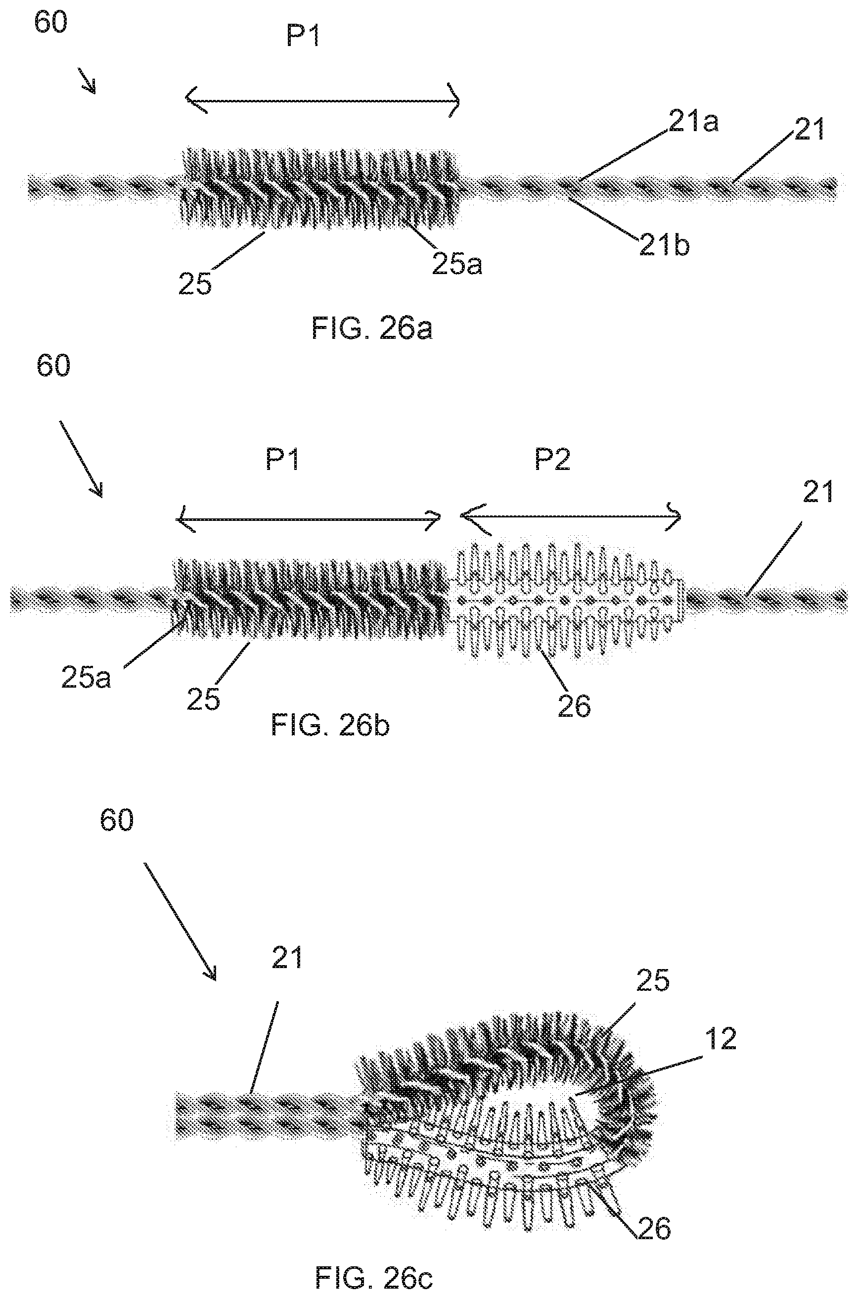
[0125] FIG. 26a-26c illustrates a series of process steps for manufacturing the applicator member of FIG. 22 in accordance with the present disclosure.
DETAILED DESCRIPTION
[0126] As shown throughout the drawings, like reference numerals designate like or corresponding parts. While illustrative embodiments of the present disclosure have been described and illustrated above, it should be understood that these are exemplary of the disclosure and are not to be considered as limiting. Additions, deletions, substitutions, and other modifications can be made without departing from the spirit or scope of the present disclosure. Accordingly, the present disclosure is not to be considered as limited by the foregoing description.
[0127] Throughout this specification, the terms "comprise," "comprises," "comprising" and the like, shall consistently mean that a collection of objects is not limited to those objects specifically recited.
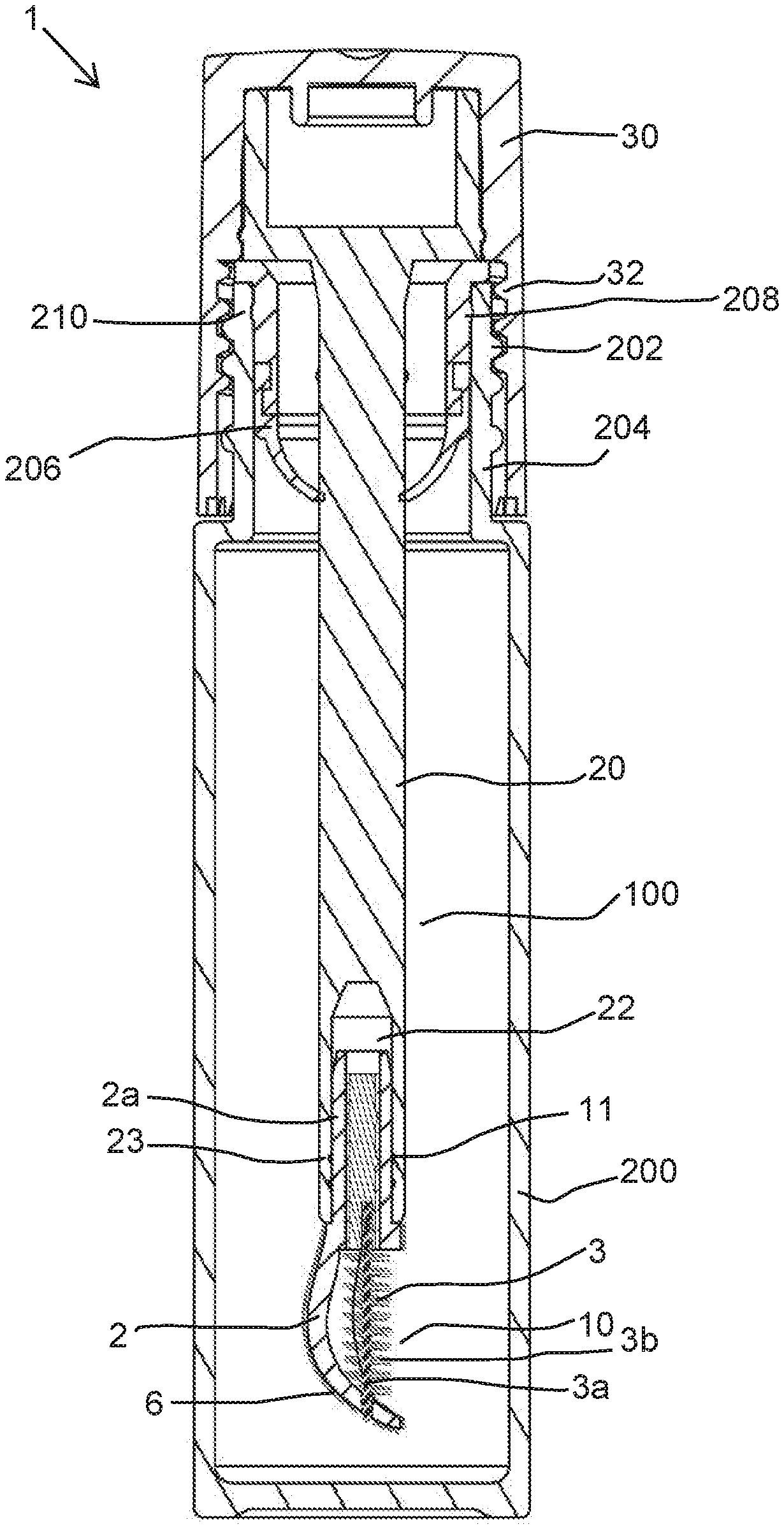
[0128] FIG. 1 illustrates a longitudinal sectional view of a cosmetic package 1. The cosmetic package 1 comprises a receptacle 200 for holding a product (not shown) and a cosmetic applicator 100. The cosmetic applicator 100 comprises an applicator head 10, a stem 20 and a cap 30. The cap 30 of the applicator 100 has threads 32 which can be screwed onto threads 202, formed on a neck 204 of the receptacle 200. Inserted in the neck 204 of the receptacle 200 is a wiper 206 for wiping off excess product from the applicator 100. The wiper 206 also comprises an annular bead 208 for engaging into a corresponding annular groove 210 on the inside of the neck 204 of the receptacle 200.
[0129] The distal end of the stem 20 includes an interior longitudinal cavity 22 for receiving and retaining the applicator head 10. The cosmetic applicator 100 may be used to apply the product (not shown) including a cosmetic or care product. The cosmetic or care product includes viscous cosmetics, mascara, eyebrow powder, lip gloss, hair color, skin care, under eye cosmetics, pharmaceutical and like products.
[0130] As shown in FIG. 1, the cosmetic applicator 100 comprises the applicator head 10 retained at the distal end of the stem 20 for applying the product; and the cap 30 at a proximal end of the stem 20. FIGS. 2-6 show the applicator head 10 according to a first embodiment of the present disclosure. As shown, the applicator head 10 comprises a first applicator member 2 and a second applicator member 3, and wherein the first applicator member 2 is configured to receive and retain the second applicator member 3. In exemplary embodiment, the first applicator member 2 is a molded applicator member and the second applicator member 3 is a twisted wire brush. The twisted wire brush 3 comprises a twisted wire core 3a and a plurality of bristles 3b extending from the core 3a. Further, the twisted wire brush 3 comprises a tip 4a, a bristled portion 4b and a tail 4c devoid of bristles 3b as seen in FIG. 5.
[0131] According to an exemplary embodiment shown in FIG. 6, the molded applicator member 2 comprises a proximal portion 2a and a distal portion 2b. According to an aspect of the present disclosure, the proximal portion 2a of the molded applicator member 2 is formed as a cylindrical shank 2a which is configured to be received within the cavity 22 of the stem 20. The molded applicator member 2 may be fixed to the stem by force fitting, in particular by snapping, gluing, welding or crimping, the shank 2a of the molded applicator member 2 in the cavity 22 of the stem 20 provided at the distal end of the stem 20.
[0132] More particularly, the shank 2a of the molded applicator member 2 includes at least one annular bead 11 and the inner surface of the stem's cavity 22 includes a corresponding annular recess 23. When the proximal end portion/shank 2a of the applicator head 10 is inserted into the interior longitudinal cavity 22 of the stem 20, the at least one annular bead 11 is snap-fitted into the corresponding annular recess 23.
[0133] According to a further aspect of the present disclosure, the distal portion 2b of the first applicator member 2 includes a root portion 2c and an arm 2d that extends along a longitudinal axis X of the applicator head 10 from the root portion 2c of the molded applicator member. The arm 2d has an X-Y axis curve with a concave inner surface 5a and a convex outer surface 5b opposite the inner surface. Thus, by X-Y axis curve, it is meant that the arm 2d is curved about both the longitudinal axis X (i.e. curved from top to bottom see FIG. 5) and a horizontal axis Y (i.e. curved from left to right shown in FIG. 3) i.e. it is curved about two mutually perpendicular axes. More particularly, the Y axis is perpendicular to the X axis.
[0134] In some examples, the arm 2d may be curved about either one or both of the X-axis and Y-axis. Thus, the arm 2d may have a semispherical curvature about X-axis and/or Y-axis. In alternate embodiments, the arm 2d may have an arcuate curvature with a changing curvature along the X-axis and/or Y-axis. In still other examples, a radius of curvature about the X-axis and the radius of curvature about the Y-axis can be equivalent, producing a spherical shape or spherical X-Y axis curve.
[0135] It is understood that the term "spherical" defines the curvature and does not infer a complete spherical shape, but rather a portion of the spherical curvature. However, the radii of curvature about the X- and Y-axes need not be the same. In some examples, the radius of curvature about the Y-axis can be greater than the radius of curvature about the X-axis. In other examples, the radius of curvature about the X-axis can be greater than the radius of curvature about the Y-axis. Thus, the arm 2d of the molded applicator member 2 includes a longitudinal concavity 5d towards the inner surface 5a which is configured for at least partially housing at least a portion of the twisted wire brush 3.
[0136] According to one embodiment, concavity 5d forms a space for holding a quantity of product to be applied by the applicator to a keratinous surface. According to a further embodiment, bristles of brush 3 extend into concavity 5d that provide additional surfaces to hold and transport the product during use. When the applicator is withdrawn from container 200 so that applicator head 10 passes through wiper 206, product retained within concavity 5d and/or on the bristles extending into the concavity, the product does not contact wiper 206. Instead, this retained product is available for application to the keratinous surface.
[0137] As seen in FIGS. 4 and 5, in the side view of the molded applicator member 2, the arm 2d has a curvature that moves away from the longitudinal axis X and then moves towards the longitudinal axis X from a proximal portion to a distal portion of the arm 2d forming a forwardly and upwardly curving hood 5c at the distal portion of the arm 2d.
[0138] According to yet another aspect of the present disclosure, the arm 2d may have application elements 6 on at least a portion of the convex outer surface 5b. The application elements 6 may be selected from a group consisting of tines, flocking, a textured surface and the like. As seen in FIGS. 1-6, the application elements 6 are flocking. The flocking 6 can be implemented on a portion of the convex outer surface 4b mechanically, electrostatically or by a combination of both technologies.
[0139] According to still further aspect of the present disclosure, the arm 2d of the molded applicator member 2 has at least 10% coverage and at most 90% coverage around the circumference/periphery of the twisted wire brush 3. According to a preferred embodiment of the present disclosure, the arm 2d of the molded applicator member 2 has at least 30% coverage and at most 80% coverage around the circumference/periphery of the twisted wire brush 3.
[0140] According to yet another aspect of the present disclosure, as shown in FIG. 5, the molded applicator member 2 further includes a hole 7a proximate to a distal end of the arm 2d and the shank 2a of the molded applicator member 2 includes a lumen 7b.
[0141] According to yet another aspect of the present disclosure, for assembling the twisted wire brush 3 and the molded applicator member 2 to form the applicator head 10, the twisted wire brush 3 is inserted through the lumen 7b of the molded applicator member 2 for fixing such that the tip 4a and the tail 4c of the twisted wire brush 3 are received respectively into the hole 7a and the lumen 7b of the molded first applicator member 2. That is in the assembled state, the tip 4a of the twisted wire brush 3 is fixed in to the hole 7a of the first applicator member 2, the bristled portion 4b of the twisted wire brush 3 is located axially adjacent to the concave inner surface 5a of the molded first applicator member 2, and the tail 4c of the twisted wire brush 3 is fixed inside the lumen 7b of the molded applicator member 2.
[0142] In some examples, the tip 4a of the twisted wire brush 3 may be fixed to the hole 7a via a glue, interference fit or by any other means known in the art. Similarly, the tail 4c of the twisted wire brush 3 may be fixed within the lumen 7b by adhesive, interference fit or by any other means known in the art. According to an embodiment and as shown, the tip 4a of the twisted wire brush 3 is fixed in to the hole 7a of the first applicator member 2 such that a distal end of the twisted wire brush 3 protrudes out from the hole 7a of the molded first applicator member 2.
[0143] In the embodiment shown, the tail 4c of the twisted wire brush 3 is held within the lumen 7b via a locking member 8. The locking member 8 comprises a housing 8a which receives the tail 4c of the twisted wire brush 3. Furthermore, in this embodiment, the locking member 8 is retained in the lumen 7b of the molded applicator member 2 by means of a retaining element, which takes the form of at least one annular groove 9 present in the lumen 7b cooperating with a corresponding at least one annular bead 8b formed on an outer surface of the locking member 8.
[0144] According to yet another aspect of the present disclosure, the twisted wire brush 3 may be cylindrical, non-cylindrical or alternatively of variable profile, when the twisted wire brush is viewed in cross-section. The cross section of the twisted wire brush 3 may be central or eccentric.
[0145] According to yet another aspect of the present embodiment, the arm 2d has a width which first increase then decreases from a proximal to a distal end of the arm 2d, as seen in FIG. 6. In other words, width of the arm 2d first increases from the root portion 2c to up to a certain length of the arm 2d and then gradually decreases towards a free end of the arm 2d.
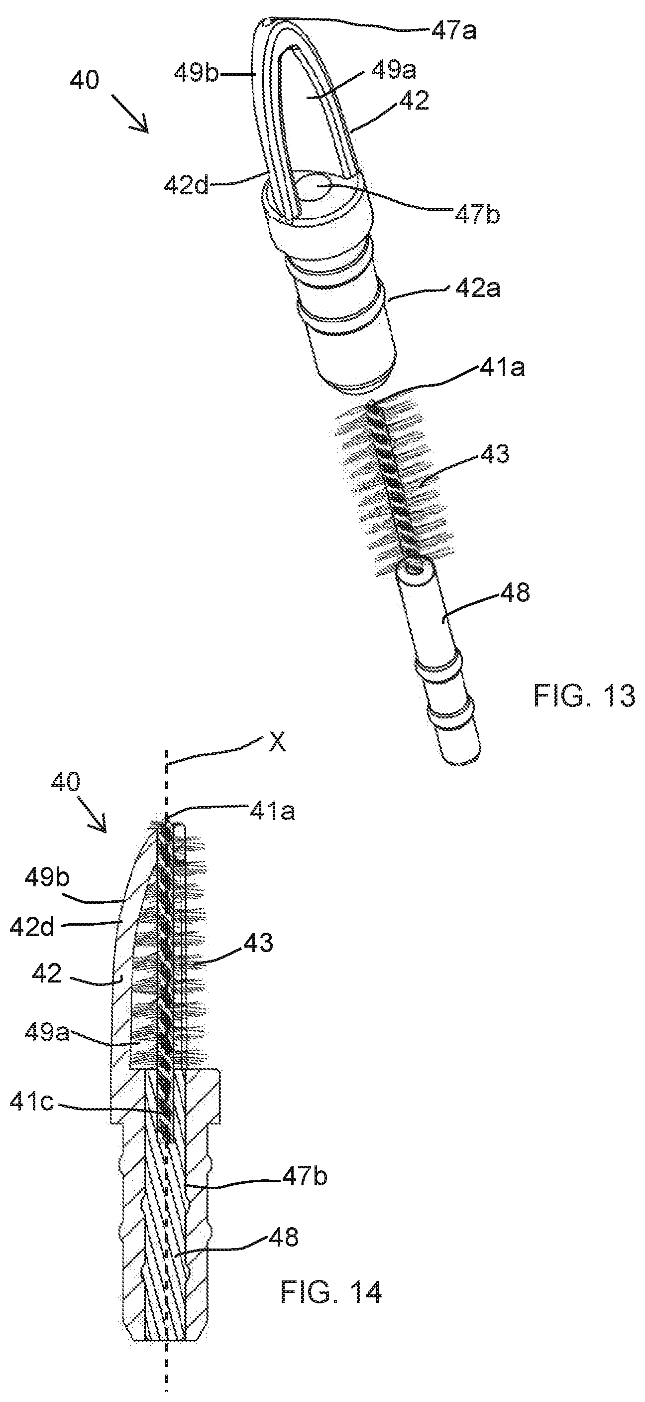
[0146] FIGS. 7-14 show a variant of the applicator head of the present disclosure according to a second embodiment. The applicator head 40 is similar to the applicator head 10 except in that the first applicator member of the applicator head 40 and the applicator head 10 differs in shape.
[0147] As seen in the FIGS. 7-14, the applicator head 40 comprises a first molded applicator member 42 and a second applicator member comprising a twisted wire brush 43. The molded applicator member 42 receives and retains the second applicator member 43 in a similar manner as discussed above for the first embodiment of the applicator head.
[0148] As seen in FIG. 13, the molded applicator member 42 includes a hole 47a proximate to a distal end of an arm 42d of the molded applicator member 42 which receives a tip 41a of the twisted wire brush 43 such that a distal end of the twisted wire brush 43 protrudes out from the hole 47a, and a shank 42a of the molded applicator member 42 includes a lumen 47b to receive a tail 41c of the twisted wire brush 43 which is held within the lumen 47b via a locking member 48.
[0149] Referring to FIGS. 7 to 12, the arm 42d is curved in both a longitudinal axis X and a horizontal axis Y of the applicator head 40. The arm 42d includes a concave inner surface 49a and a convex outer surface 49b opposite the inner surface 49a. The arm 42d of the molded applicator member 42 is seen to include opposite sides 46a and 46b interconnected by means of a smooth transitional side 46c, see FIG. 9.
[0150] As with the previous embodiment, the concavity formed by concave inner surface 49a forms a reservoir for holding a quantity of the product to be applied by the user. According to one embodiment, bristles of brush 43 extend into this concavity and provide additional surfaces to hold the product. Because product is held with the concavity, when the applicator is removed from container 200, wiper 206 does not contact the inside of the concavity or the bristles extending into the concavity, thus allowing product held thereon to be available for the user to apply to a keratinous surface.
[0151] The arm 42d is substantially V-shaped in transverse cross-section (not shown) forming a substantially V-shaped concavity towards its inner surface 49a. The inner surface 49a faces the central longitudinal axis X of the applicator head 40.
[0152] As seen in the side view of the molded applicator member 42, the arm 42d has a curvature comprising a forwardly and upwardly curving bow portion 45a smoothly curving inwardly towards the axis X and a substantially longitudinally straight proximal portion 45b.
[0153] According to an aspect of the present disclosure, the molded applicator member 42 may not be flocked as shown in FIGS. 7-12.
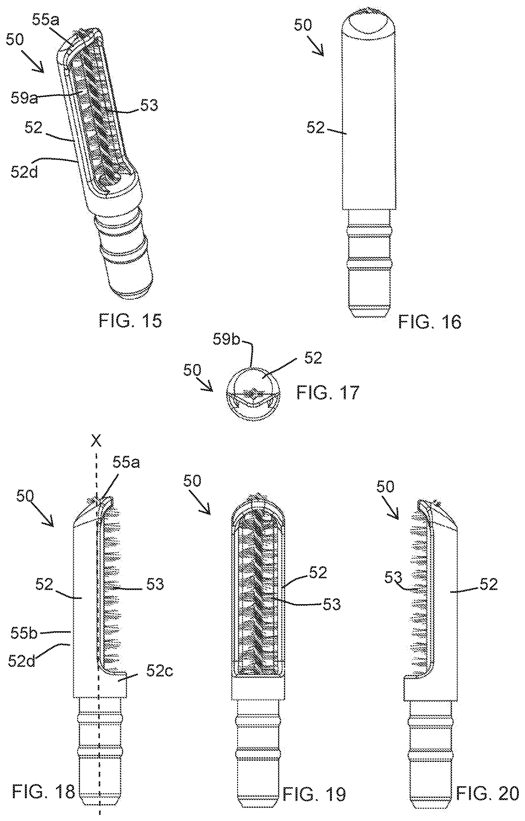
[0154] FIGS. 15-20 show a variant of the applicator head of the present disclosure according to a third embodiment. The applicator head 50 is similar to the applicator heads 10 and 40 except in that the molded applicator member 52 differs in shape. An arm 52d of the molded applicator member 52 extends along a central longitudinal axis X of the applicator head 50. The arm 52d is curved in the transverse axis Y of the applicator head 50. The arm 52d includes a concave inner surface 59a and a convex outer surface 59b opposite the inner concave surface 59a. The arm 52d of the molded applicator member 52 is seen to have a semi-cylindrical sidewall having a substantially C-shaped transverse cross-section (not shown) forming a substantially C-shaped concavity towards its inner surface 59a. Again, as discussed with respect to the previous embodiments, this concavity, and bristles from brush 53 extending into this concavity form a reservoir for holding product.
[0155] As seen in the side view of the molded applicator member 52, the arm 52d has a substantially longitudinally straight portion 55b along the longitudinal axis X and has a curvature at the distal end portion forming a forwardly and upwardly curving hood 55a at the distal end portion of the arm 52d, i.e. the arm 52d runs substantially parallel to the longitudinal axis X from a root portion 52c of the molded applicator member 52 and smoothly curves inwardly towards the longitudinal axis X towards the distal end portion of the arm 52d.
[0156] In variant embodiments, the first applicator member 2, 42, 52 may be of any other desirable shape as long as it includes a longitudinal concavity for at least partially housing a twisted wire brush and extends around at least 10% periphery of the twisted wire brush 3, 43, 53.
[0157] However, in a variant embodiment, the plurality of application elements is adapted to convey and apply the cosmetic product. In present embodiment, the application elements are flocking, however in variant embodiments, the application elements may be projections, bristles, tines, particles, ribs, grooves, discs, slits, cuts, holes, dimples, foam or other surface features or surface treatments (e.g., abrading) that are suitable for combing and/or loading, transporting and applying cosmetic product such as, for example, mascara, eyeshadow etc.
[0158] According to an aspect of the present disclosure, the plurality of application elements 9 is spread over at least 40% of an outer surface area of the distal portion of the first applicator member 2, 42, 52. In an exemplary use of the cosmetic applicator 100 of the present disclosure, the cosmetic applicator 100 may be used for applying a product to eyebrows.
[0159] According to yet another aspect of the present embodiment, the longitudinal concavity of the molded applicator member 2, 42, 52 helps in retaining the cosmetic product which is available for loading, transporting and applying after wiping of the applicator head 10.
[0160] According to an alternate embodiment of the present disclosure, at least a portion of one of the molded applicator member (2, 42, 52) and the twisted wire brush (3, 43, 53) is covered by a flock coating. According to an alternate embodiment of the present disclosure, the application bristles 3b of the twisted wire brush 3 may be covered by a flock coating.
[0161] According to an embodiment of the present disclosure, the molded applicator member 2, 42, 52 may be fabricated from a material selected from a group consisting of plastic, metal, alloy, ceramic, stone, wood, rubber, sintered or porous material and/or combinations thereof.
[0162] FIG. 21 shows a cosmetic package 1 according to a fourth embodiment of the present disclosure, comprising a cosmetic applicator 100 and an associated container 200 containing a product P to be applied to the eyelashes and/or the eyebrows, for example mascara or a care product. The product may include a solid, liquid, semi-liquid, creamy, powder, paste-like or viscous material.
[0163] The container 200 comprises, in the example considered, a threaded neck 32 and the cosmetic applicator 100 comprises a gripping member 30 also constituting a closure cap arranged to attach to the neck 32 in order to close the container 200 in a sealed manner
[0164] The cosmetic applicator 100 comprises a stem 20, which is connected at its upper end to the gripping member 30 and, at its lower end, to an applicator member 60 having a looped configuration. Further, the applicator member 60 can be used for applying a cosmetic product such as mascara or the like, to eyelashes or eyebrows for providing multiple performance characteristics like separation/combing, volumizing, curling and lengthening.
[0165] The container 200 also comprises a wiper member 206, for example, inserted into the neck 32. This wiper member 206 cleans the stem 20 and the applicator member 60 when the cosmetic applicator 100 is removed from the container 200.
[0166] In the example considered, a longitudinal axis of the stem 20 is rectilinear, but it is not beyond the scope of this disclosure when the stem 20 is non-rectilinear, forming, for example, a bended stem 20.
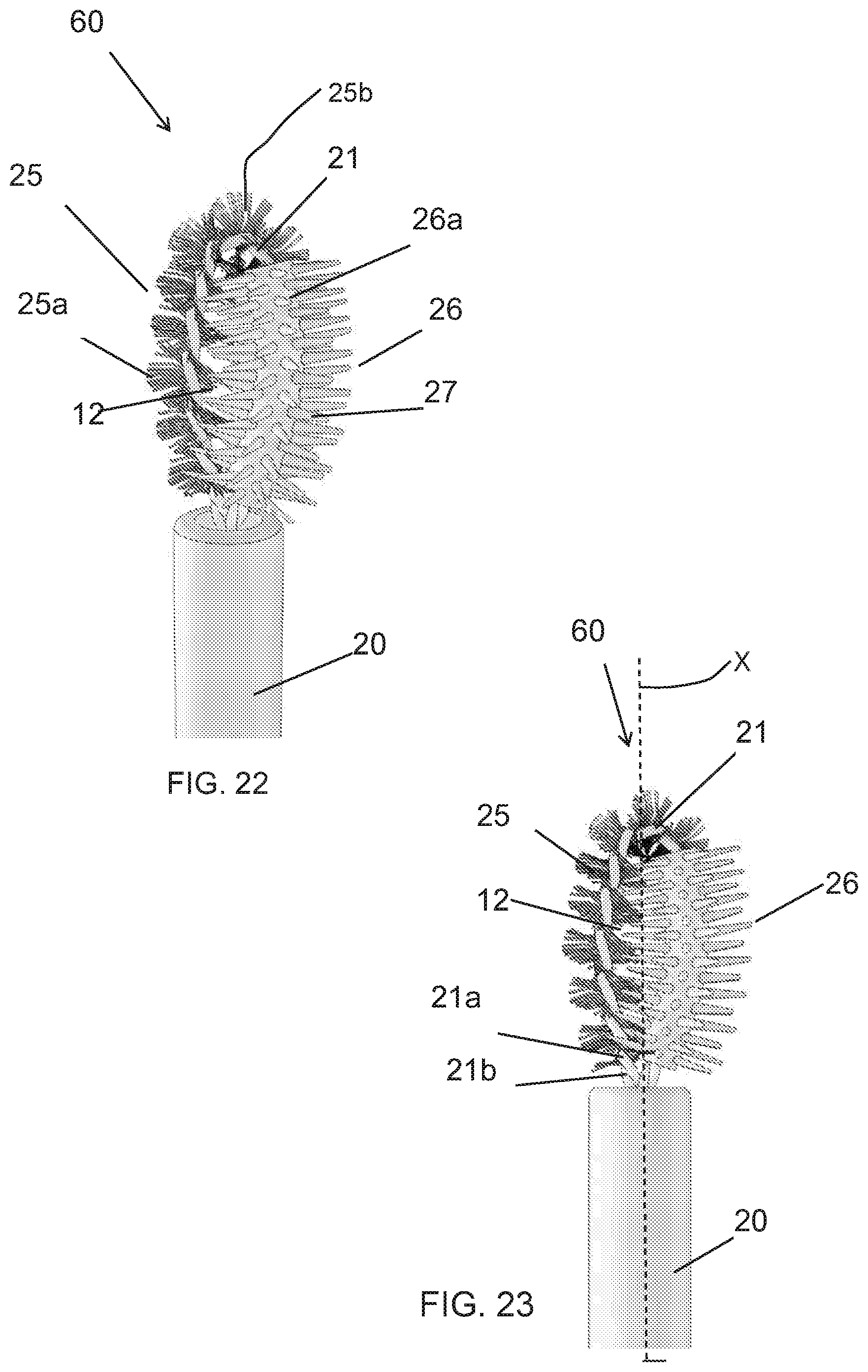
[0167] As seen in FIGS. 22-23, the applicator member 60 comprises a twisted wire core 21 that is elongate along a longitudinal axis X. The twisted wire core 21 is formed from a pair of wire segments 21a, 21b which are intertwisted. The twisted wire core 21 is bent to form a loop, i.e. the twisted wire core 21 is a looped core 21, and free ends of the twisted core 21 being connected to the stem 20, as shown in FIG. 24.
[0168] According to an alternate embodiment, the free ends of the core 21 may be connected with each other--not shown in the drawing--to form a handle. According to one embodiment, the ends of the twisted wire core 21 are brought together in parallel and arranged adjacent one another along the longitudinal axis of the applicator to form a shank of the applicator head. This shank may be inserted into the distal end of the stem 20, as shown in FIG. 24.
[0169] Referring to FIGS. 22-25, the applicator member 60 comprises, a twisted wire brush portion 25 with a twisted wire core 21 and a molded brush portion 26 disposed on the twisted wire core 21. The molded brush portion 26 comprises a support body 26a carrying teeth 27, as shown in FIG. 22.
[0170] More specifically, as shown in FIGS. 26a and 26b, the twisted wire core 21 includes at least two portions P1, P2, and wherein one of the at least two portions P1, P2 is located near one of the two free ends of the twisted wire core 21, and wherein other of the at least two portions P1, P2 lies closer to other of the two free ends of the twisted wire core 21. Further, a first portion P1 of the twisted wire core 21 is occupied by the twisted wire brush portion 25 which is formed by a plurality of bristles 25a secured between the pair of intertwisted wire segments 21a, 21b. The bristles 25a are secured between the intertwisted wire segments 21a, 21b of the twisted wire core 21 such that opposite ends of each bristle 25a extend radially from the twisted wire core 21. Various fibers may be used for the bristles 25a, depending on the desired properties of the finished twisted wire brush portion 25.
[0171] A second portion P2 of the twisted wire core 21 is occupied by the molded brush portion 26 which is sleeved onto the twisted wire core 21. The molded brush portion 26 includes a through passage 26b (see FIG. 25), due to which the molded brush portion 26 is sleeved onto the twisted wire core 21. More specifically, the support body 26a of the molded brush portion 26 has a longitudinal through passage 26b, traversed over its entire length by the second portion P2 of the twisted wire core 21 to allow attachment of one of the two ends of twisted wire core 21 to the stem 20. The molded brush portion 26 is located between the stem 20 and the twisted wire brush portion 25. Similarly, the twisted wire brush portion 25 is located between the stem 20 and the molded brush portion 26.
[0172] In the preferred embodiment shown in FIGS. 21 and 22, length of the second portion P2 of the twisted wire core 21 occupied by the molded applicator potion 26 is less than the length occupied by the first portion P1 of the twisted wire core 21 carrying the bristles 25a of the twisted wire brush portion 25. In the preferred embodiment, as shown in FIGS. 22 and 26b, the first portion P1 and second portion P2 are adjacent to each other in the loop defined by the twisted wire core 21 and wherein the second portion P2 carrying the molded brush portion 26 lies entirely on one side of a longitudinal axis X of the applicator member 60, and the first portion P1 carrying the twisted wire brush portion 25 extends majorly on the other side of the longitudinal axis X and on distal portion forming a fanned bristled tip 25b. Thus, the twisted wire brush portion 25 and the molded brush portion 26 are arranged substantially side by side in the continuous loop of the twisted wire core 21.
[0173] In an alternate embodiment, the length P2 occupied by the molded brush portion 26 may be greater than the length occupied by the first portion P1 of the twisted wire core 21 carrying the bristles 25a of the twisted wire brush portion 25. In still other alternate embodiments, the first portion P1 of the twisted wire core 21 forming the twisted wire brush portion 25 and the second portion P2 of the twisted wire core 21, are substantially of equal length and coextensive. However, it will be understood that configurations are contemplated wherein the first portion P1 of the twisted wire core 21 forming the twisted wire brush portion 25 and the second portion P2 of the twisted wire core 21 holding the molded brush portion 26 are not coextensive either because each has a different length, and/or because each has a length offset relative to the length of the other.
[0174] In the example illustrated in FIGS. 21 to 26c, the applicator member 60 comprises single molded brush portion 26, but it is not beyond the scope of the present disclosure if it is otherwise.
[0175] Referring to FIGS. 22-24, The twisted wire core 21 defines a single opening 12 which it surrounds completely, because of which the applicator member 60 acquires a loop-type configuration comprising an internal chamber or reservoir 12 entirely encased by the twisted wire core 21. At least a few bristles 25a of twisted wire brush portion 25 and at least a few teeth 27 of the molded brush portion 26 extend in the opening 12 defined by the twisted wire core 21. More particularly, the bristles 25a of the twisted wire brush portion 25 and the teeth 27 of the molded brush portion 26 are interleaved in said reservoir 12 i.e. the interior bristles 25a and interior teeth 27 meet and/or overlap resulting in an internal chamber or reservoir 12 filled with bristles 25a and teeth 27. In an alternate embodiment, the bristles 25a and teeth 27 projecting toward the interior of the loop/opening 12 do not meet, resulting in a gap between their tips thereby resulting in an open internal chamber or reservoir 12, as shown in FIG. 26c. According to one embodiment, the distal end 20a of stem 20 forms a shank for receiving the ends of the twisted wire core 21, as shown in FIG. 24.
[0176] The opening 12 formed by the looped twisted wire core 21 forms a reservoir for holding a quantity of the product to be applied by the user. According to one embodiment, bristles 25a and teeth 27 extend into this opening and provide additional surfaces to hold the product. Because product is held with the opening, when the applicator is removed from container 200, wiper 206 does not contact the inside of opening 12 and also does not contact the bristles 25a and teeth 27 that extend into the opening 12, thus allowing product held thereon to be available for the user to apply to a keratinous surface.
[0177] In the embodiment according to FIGS. 22 to 24, the loop configuration of twisted wire core 21 or the applicator member 60 has a substantially symmetric oval shape. However, in alternate embodiments, said loop may have any desirable shape such as a rectangular shape, asymmetric drop-shaped, a circular configuration or any other desirable shape.
[0178] As seen in FIGS. 21-22, both the molded brush portion 26 and the twisted wire brush portion 25 are curved, and they follow the curve of the loop defined by the twisted wire core 21.
[0179] Further, the bristles 25a has free ends defining the envelope surface of the twisted wire brush portion 25, and free ends of the teeth 27 define the envelop surface of the molded brush portion 26. As shown in FIGS. 21-25, the bristles 25a and the teeth 27 exhibit a cylindrical envelope surface. Consequently, the bristles 25a are suitable for combing and separating the eyelashes or eyebrows, and teeth 27 are suitable for applying the cosmetic product. The envelope surface of the twisted wire brush portion 25 and the envelope surface of the molded brush portion 26 may be in the extension of one another without forming a discontinuity. However, as seen in FIGS. 22-23, the envelope surface of the twisted wire brush portion 25 and the envelope surface of the molded brush portion 26 do not flush each other and form a discontinuity.
[0180] According to an aspect of the present disclosure, the bristles 25a contemplated for use with the present applicator member 60 include one or a combination of circular, non-circular, and hollow cross-sections. The bristles 25a may be natural or plastic fibers. In the case of plastic fibers, they may be polyamide, polyester or polyacrylic fibers.
[0181] The twisted wire brush portion 25 and/or the molded brush portion 26 may be cylindrical or alternatively of generally variable shape, for example lenticular, or drop-shaped, or frustoconical. As a variant again, the twisted wire brush portion 25 and/or the molded brush portion 26 may be shaped similar to a peanut or a ball. When the twisted wire brush portion 25 and/or the molded brush portion 26 is viewed in cross-section, the twisted wire core 21 may be central (not shown). Alternatively, the twisted wire core 21 may be eccentric in the cross section of the twisted wire brush portion 25 and/or the molded brush portion 26. The support body 26a of the molded brush portion 26 may be in cross section of any shape, for example circular, as shown in FIG. 25 or polygonal.
[0182] According to an aspect of the present disclosure, the teeth 27 contemplated for use with the present applicator member 24 may have a cross-section or combination of cross-sections selected from a group consisting of circular, non-circular, semi-circular, elliptical, semi-elliptical, polygonal, in particular triangular, square, rectangular, octagonal, parallelogram-shaped, lozenge-shaped; oval, and the like cross-sections. The teeth 27 may optionally be rectilinear, e.g. each extending along a long axis for the tooth that is rectilinear, or else they may be curved, or they may even be undulating. The term "long axis of the tooth" is used to mean an axis that passes via the centers of gravity of the cross-sections of the tooth 27.
[0183] The teeth 27 may be molded integrally with the support body 26a, said teeth 27 may be of any shape and have any disposition, e.g. a staggered configuration, or with their bases in alignment.
[0184] According to an aspect of the present disclosure, the molded brush portion 26 may be free to rotate on the twisted wire core 21 or it can be immobilized relative to the twisted wire core 21.
[0185] It is possible to use for molding the brush portion 26, a thermoplastic material that is relatively rigid or not, particularly flexible, for example SEBS, a silicone, a latex, a butyl, a PEPDM, a nitrile, a thermoplastic elastomer, a rubber elastomer, polyester, polyamide, polyethylene or vinyl, a polyolefin such as PE or PP, PVC, EVA, PS, PET, POM, PA or PMMA, PV, SIS or SEBS. In particular, materials known as Hytrel.RTM., Cariflex.RTM., Alixine.RTM., Santoprene.RTM., Pebax.RTM. can be used, this list not being limiting. The molded brush portion 26 may also be made of metal. The teeth 27 are made in the example considered in one piece by molding thermoplastic material with the support body 26a.
[0186] The teeth 27 and the support body 26a may be made of different materials, if appropriate.
[0187] The molded brush portion 26 may be made with a flocking, the latter extending for example on the teeth 27 only or on the support body 26a only or on both. The teeth 27 may have, at their free end, a relief or a particular shape, for example a fork, a ball or a hook.
[0188] The wiper 206 may be rigid or of elastomeric material. The wiper 206 may be made of a material, for example, a polyolefin or an elastomer. The polyolefin may be polyethylene, for example, such as low- or high-density polyethylene.
[0189] The stem 20 may be rectilinear, curved, may be bendable, may have an elbow, etc. The handle and the stem 20 may be constructed of plastic (e.g., polypropylene (PP), acrylontrile butadiene styrene (ABS), Polyoxymethylene (POM)), or any other suitable material.
[0190] The product P may be in the form of, for example, powder, liquids, gels, creams, oil-based products, wax-based products, water-based products, or the like.
[0191] According to yet another aspect of the present disclosure, the container 200 may be made of a plastic material, glass or any suitable material known in the prior art.
[0192] Referring to FIGS. 26a-26c, a method is provided for forming the applicator member 60 of the present disclosure. A method of making the applicator member 60, comprises the steps of
[0193] (a) forming a twisted wire brush portion 25 in a first portion P1 of a rectilinear twisted wire core 21 by securing a plurality of bristles 25a between the pair of intertwisted wire segments 21a, 21b of the first portion P1, such that the plurality of bristles 25a extends radially therefrom.
[0194] (b) passing the second portion P2 of the twisted wire core 21 through the through passage 26b of the molded brush portion 26 so as to receive the molded brush portion 26 in the second portion P2 of the twisted wire core 21.
[0195] (c) bending the twisted wire core 21 to form a loop.
[0196] Although, the present disclosure has been described with reference to exemplary embodiments, it is not limited thereto. Those skilled in the art will appreciate that numerous changes and modifications may be made to the preferred embodiments of the present disclosure and that such changes and modifications may be made without departing from the true spirit of the present disclosure. It is therefore intended that the appended claims be construed to cover all such equivalent variations as fall within the true spirit and scope of the present disclosure.
* * * * *
D00000
D00001
D00002
D00003
D00004
D00005
D00006
D00007
D00008
D00009
XML
uspto.report is an independent third-party trademark research tool that is not affiliated, endorsed, or sponsored by the United States Patent and Trademark Office (USPTO) or any other governmental organization. The information provided by uspto.report is based on publicly available data at the time of writing and is intended for informational purposes only.
While we strive to provide accurate and up-to-date information, we do not guarantee the accuracy, completeness, reliability, or suitability of the information displayed on this site. The use of this site is at your own risk. Any reliance you place on such information is therefore strictly at your own risk.
All official trademark data, including owner information, should be verified by visiting the official USPTO website at www.uspto.gov. This site is not intended to replace professional legal advice and should not be used as a substitute for consulting with a legal professional who is knowledgeable about trademark law.