Compressor Stator Vane Unit, Compressor, And Gas Turbine
SEKI; Ryosuke
U.S. patent application number 16/787405 was filed with the patent office on 2020-10-15 for compressor stator vane unit, compressor, and gas turbine. The applicant listed for this patent is MITSUBISHI HEAVY INDUSTRIES, LTD.. Invention is credited to Ryosuke SEKI.
| Application Number | 20200325787 16/787405 |
| Document ID | / |
| Family ID | 1000004668900 |
| Filed Date | 2020-10-15 |
| United States Patent Application | 20200325787 |
| Kind Code | A1 |
| SEKI; Ryosuke | October 15, 2020 |
COMPRESSOR STATOR VANE UNIT, COMPRESSOR, AND GAS TURBINE
Abstract
A compressor stator vane unit includes multiple compressor stator vanes disposed at a certain interval in a circumferential direction; and an annular joint member connected with inner ends of the multiple compressor stator vanes; wherein the annular joint member constitutes an outer diameter side surface of a leakage fluid flow path provided in an inner diameter side of the joint member to communicate a high-pressure space with a low-pressure space respectively located downstream and upstream of the multiple compressor stator vanes in a fluid flow direction, and D/P is set to 0.05.ltoreq.D/P.ltoreq.0.2, wherein D is defined as a distance in an axial direction between an upstream end surface of the annular joint member and an upstream edge of the multiple compressor stator vanes in the fluid flow direction and P is defined as a pitch between the adjacent compressor stator vanes in the circumferential direction.
| Inventors: | SEKI; Ryosuke; (Tokyo, JP) | ||||||||||
| Applicant: |
|
||||||||||
|---|---|---|---|---|---|---|---|---|---|---|---|
| Family ID: | 1000004668900 | ||||||||||
| Appl. No.: | 16/787405 | ||||||||||
| Filed: | February 11, 2020 |
| Current U.S. Class: | 1/1 |
| Current CPC Class: | F01D 9/041 20130101; F05D 2240/12 20130101; F05D 2240/80 20130101; F05D 2240/55 20130101; F01D 11/001 20130101; F01D 11/02 20130101; F04D 29/324 20130101; F05D 2240/35 20130101; F05D 2240/30 20130101 |
| International Class: | F01D 11/00 20060101 F01D011/00; F01D 9/04 20060101 F01D009/04 |
Foreign Application Data
| Date | Code | Application Number |
|---|---|---|
| Apr 10, 2019 | JP | 2019-075188 |
Claims
1. A compressor stator vane unit comprising: multiple compressor stator vanes disposed at a certain interval in a circumferential direction; and an annular joint member connected with inner ends of the multiple compressor stator vanes; wherein the annular joint member constitutes an outer diameter side surface of a leakage fluid flow path which is provided in an inner diameter side of the joint member and which communicates a high-pressure space located downstream of the multiple compressor stator vanes in a fluid flow direction with a low-pressure space located upstream of the multiple compressor stator vanes in the fluid flow direction, and D/P is set to a range: 0.05.ltoreq.D/P.ltoreq.0.2, wherein D is defined as a distance in an axial direction between an upstream end surface of the annular joint member in the fluid flow direction and an upstream edge of the multiple compressor stator vanes in the fluid flow direction, and P is defined as a pitch between the adjacent compressor stator vanes in the circumferential direction.
2. The compressor stator vane unit according to claim 1, wherein D/P is set to a range: 0.06.ltoreq.D/P.ltoreq.0.18.
3. A compressor stator vane unit comprising: multiple compressor stator vanes disposed at a certain interval in a circumferential direction; and an annular joint member connected with inner ends of the multiple compressor stator vanes; wherein the annular joint member constitutes an outer diameter side surface of a leakage fluid flow path which is provided in an inner diameter side of the joint member and which communicates a high-pressure space located downstream of the multiple compressor stator vanes in a fluid flow direction with a low-pressure space located upstream of the multiple compressor stator vanes in the fluid flow direction, and D/T is set to a range: 0.3.ltoreq.D/T.ltoreq.1.2, wherein D is defined as a distance in an axial direction between an upstream end surface of the annular joint member in the fluid flow direction and an upstream edge of the multiple compressor stator vanes in the fluid flow direction, and T is defined as a maximum thickness of each of the multiple compressor stator vanes, D/T is set to a range: 0.3.ltoreq.D/T.ltoreq.1.2.
4. The compressor stator vane unit according to claim 3, wherein D/T is set to a range: 0.4.ltoreq.D/T.ltoreq.1.1.
5. A compressor comprising: a casing; a rotation shaft disposed in and rotatably supported by the casing; the multiple compressor stator vane units according to claim 1, the compressor stator vane units being fixed to an inner circumferential surface of the casing at a certain interval in the axial direction of the rotation shaft; and multiple compressor rotor blade units fixed to an outer circumference of the rotation shaft at a certain interval in the axial direction and each of the multiple compressor rotor blade units includes multiple compressor rotor blades fixed to the outer circumference of the rotation shaft at a certain interval in a circumferential direction.
6. A compressor comprising: a casing; a rotation shaft disposed in and rotatably supported by the casing; the multiple compressor stator vane units according to claim 2, the compressor stator vane units being fixed to an inner circumferential surface of the casing at a certain interval in the axial direction of the rotation shaft; and multiple compressor rotor blade units fixed to an outer circumference of the rotation shaft at a certain interval in the axial direction and each of the multiple compressor rotor blade units includes multiple compressor rotor blades fixed to the outer circumference of the rotation shaft at a certain interval in a circumferential direction.
7. A compressor comprising: a casing; a rotation shaft disposed in and rotatably supported by the casing; the multiple compressor stator vane units according to claim 3, the compressor stator vane units being fixed to an inner circumferential surface of the casing at a certain interval in the axial direction of the rotation shaft; and multiple compressor rotor blade units fixed to an outer circumference of the rotation shaft at a certain interval in the axial direction and each of the multiple compressor rotor blade units includes multiple compressor rotor blades fixed to the outer circumference of the rotation shaft at a certain interval in a circumferential direction.
8. A compressor comprising: a casing; a rotation shaft disposed in and rotatably supported by the casing; the multiple compressor stator vane units according to claim 4, the compressor stator vane units being fixed to an inner circumferential surface of the casing at a certain interval in the axial direction of the rotation shaft; and multiple compressor rotor blade units fixed to an outer circumference of the rotation shaft at a certain interval in the axial direction and each of the multiple compressor rotor blade units includes multiple compressor rotor blades fixed to the outer circumference of the rotation shaft at a certain interval in a circumferential direction.
9. A gas turbine comprising: the compressor according to claim 5; a combustor configured to mix compressed air compressed by the compressor with a fuel to burn the mixture; and a turbine rotationally driven by combustion gas generated by the combustor.
10. The gas turbine according to claim 9, wherein a rated speed of the gas turbine is set to a range from 2500 rpm to 4000 rpm.
11. The gas turbine according to claim 9, wherein a velocity of fluid flowing in the axial direction through a region between the compressor stator vanes at a rated speed range is set to a range from 50 m/s to 200 m/s.
Description
CROSS-REFERENCE TO RELATED APPLICATIONS
[0001] The present application claims priority to and incorporates by reference the entire contents of Japanese Patent Application No. 2019-075188 filed in Japan on Apr. 10, 2019.
FIELD
[0002] The present invention relates to a compressor stator vane unit including compressor stator vanes disposed at certain intervals in a circumferential direction, a compressor including the compressor stator vane unit, and a gas turbine including the compressor.
BACKGROUND
[0003] A gas turbines includes a compressor, a combustor, and a turbine. The compressor includes a plurality of compressor stator vanes and a plurality of compressor rotor blades that are alternately arranged in a casing. The compressor stator vanes are disposed at certain intervals in a circumferential direction and outer ends of the compressor stator vanes are fixed to an inner circumferential surface of the casing. The compressor rotor blades are disposed at certain intervals in the circumferential direction and inner ends of the compressor rotor blades are fixed to an outer circumference of a rotor that is rotatably supported by the casing. Inner ends of the compressor stator vanes are fixed to an annular shroud. A seal member is provided between the shroud and the rotor.
[0004] The compressor compresses air taken from an air intake to generate high-temperature and high-pressure compressed air. The pressure of the air increases as the air flows downstream in an air flow direction. The compressed air having a higher pressure at a downstream side of the compressor stator vanes tends to flow into the compressed air having a lower pressure at an upstream side of the compressor stator vanes through a cavity provided between the shroud and the rotor. Although the seal member is provided, it is difficult to completely eliminate a leakage of the compressed air. If the compressed air leaks from the downstream side to the upstream side of the compressor stator vanes through the cavity and mixes with a main flow of the compressed air, a secondary flow is generated and pressure loss occurs.
[0005] Conventional techniques for solving the problem above are disclosed in, for example, Patent Literatures below.
CITATION LIST
Patent Literature
[0006] Patent Literature 1: Japanese Patent Application Laid-open No. 2006-233787
[0007] Patent Literature 2: Japanese Patent No. 5651459
SUMMARY
Technical Problem
[0008] Conventional compressors described in Patent Literatures above include a swirler or tangential flow inducers provided in a leakage flow path of the compressed air. However, this configuration may increase structural complexity and manufacturing cost.
[0009] The present invention has been made in view of the foregoing, and it is an object of the present invention to provide a compressor stator vane unit, a compressor, and a gas turbine that prevent leakage fluid from flowing out without increasing the structural complexity or the manufacturing cost, and prevent pressure loss.
Solution to Problem
[0010] According to one aspect of the present invention, there is provided a compressor stator vane unit comprising: multiple compressor stator vanes disposed at a certain interval in a circumferential direction; and an annular joint member connected with inner ends of the multiple compressor stator vanes; wherein the annular joint member constitutes an outer diameter side surface of a leakage fluid flow path which is provided in an inner diameter side of the joint member and which communicates a high-pressure space located downstream of the multiple compressor stator vanes in a fluid flow direction with a low-pressure space located upstream of the multiple compressor stator vanes in the fluid flow direction, and D/P is set to a range: 0.05.ltoreq.D/P.ltoreq.0.2, wherein D is defined as a distance in an axial direction between an upstream end surface of the annular joint member in the fluid flow direction and an upstream edge of the multiple compressor stator vanes in the fluid flow direction, and P is defined as a pitch between the adjacent compressor stator vanes in the circumferential direction.
[0011] Setting a relation between the distance D which is in the axial direction between the opening of the leakage fluid flow path close to the low-pressure space and the upstream edge of the compressor stator vanes and the pitch P between the compressor stator vanes in the circumferential direction to an appropriate range can prevent interference between the main fluid flow and the leakage fluid and can prevent generation of a secondary flow, when the fluid in the high-pressure space leaks into the low-pressure space through the leakage fluid flow path. Therefore, the compressor stator vane unit can prevent leakage fluid from flowing out without increasing the structural complexity or the manufacturing cost, and can prevent pressure loss.
[0012] According to one aspect of the present invention, there is provided the compressor stator vane unit described above, wherein D/P is set to a range: 0.06.ltoreq.D/P.ltoreq.0.18.
[0013] This configuration can effectively prevent the interference between the main fluid flow and the leakage fluid and can prevent the generation of the secondary flow when the fluid in the high-pressure space leaks into the low-pressure space through the leakage fluid flow path.
[0014] According to one aspect of the present invention, there is provided a compressor stator vane unit comprising: multiple compressor stator vanes disposed at a certain interval in a circumferential direction; and an annular joint member connected with inner ends of the multiple compressor stator vanes; wherein the annular joint member constitutes an outer diameter side surface of a leakage fluid flow path which is provided in an inner diameter side of the joint member and which communicates a high-pressure space located downstream of the multiple compressor stator vanes in a fluid flow direction with a low-pressure space located upstream of the multiple compressor stator vanes in the fluid flow direction, and D/T is set to a range: 0.3.ltoreq.D/T.ltoreq.1.2, wherein D is defined as a distance in an axial direction between an upstream end surface of the annular joint member in the fluid flow direction and an upstream edge of the multiple compressor stator vanes in the fluid flow direction, and T is defined as a maximum thickness of each of the multiple compressor stator vanes, D/T is set to a range: 0.3.ltoreq.D/T.ltoreq.1.2.
[0015] Setting the relation between the distance D which is in the axial direction between the opening of the leakage fluid flow path close to the low-pressure space and the upstream edge of the compressor stator vanes and the maximum thickness of the compressor stator vane T to the appropriate range can prevent interference between the main fluid flow and the leakage fluid and can prevent generation of a secondary flow, when the fluid in the high-pressure space leaks into the low-pressure space through the leakage fluid flow path. Therefore, the compressor stator vane unit can prevent leakage fluid from flowing out without increasing the structural complexity or the manufacturing cost, and can prevent pressure loss.
[0016] According to one aspect of the present invention, there is provided the compressor stator vane unit described above, wherein D/T is set to a range: 0.4.ltoreq.D/T.ltoreq.1.1.
[0017] This configuration can effectively prevent the interference between the main fluid flow and the leakage fluid and can prevent the generation of the secondary flow when the fluid in the high-pressure space leaks into the low-pressure space through the leakage fluid flow path.
[0018] According to one aspect of the present invention, there is provided a compressor comprising: a casing; a rotation shaft disposed in and rotatably supported by the casing; the multiple compressor stator vane units described above, the compressor stator vane units being fixed to an inner circumferential surface of the casing at a certain interval in the axial direction of the rotation shaft; and multiple compressor rotor blade units fixed to an outer circumference of the rotation shaft at a certain interval in the axial direction and each of the multiple compressor rotor blade units includes multiple compressor rotor blades fixed to the outer circumference of the rotation shaft at a certain interval in a circumferential direction.
[0019] The compressor can prevent the leakage fluid from flowing out without increasing the structural complexity or the manufacturing cost, and can prevent the pressure loss.
[0020] According to one aspect of the present invention, there is provided a gas turbine comprising: the compressor described above; a combustor configured to mix compressed air compressed by the compressor with a fuel to burn the mixture; and a turbine rotationally driven by combustion gas generated by the combustor.
[0021] The gas turbine can prevent the leakage fluid from flowing out without increasing the structural complexity or the manufacturing cost, and can prevent the pressure loss.
[0022] According to one aspect of the present invention, there is provided the gas turbine described above, wherein a rated speed of the gas turbine is set to a range from 2500 rpm to 4000 rpm.
[0023] The gas turbine on operating at a rated speed can effectively prevent the interference between the main fluid flow and the leakage fluid and can prevent the generation of the secondary flow when the fluid in the high-pressure space leaks into the low-pressure space through the leakage fluid flow path.
[0024] According to one aspect of the present invention, there is provided the gas turbine described above, wherein a velocity of fluid flowing in the axial direction through a region between the compressor stator vanes at a rated speed range is set to a range from 50 m/s to 200 m/s.
[0025] The gas turbine on operating at the rated speed can effectively prevent the interference between the main fluid flow and the leakage fluid and can prevent the generation of the secondary flow when the fluid in the high-pressure space leaks into the low-pressure space through the leakage fluid flow path.
[0026] The compressor stator vane unit, the compressor, and the gas turbine according to the present invention can prevent the leakage fluid from flowing out without increasing the structural complexity or the manufacturing cost, and can prevent the pressure loss.
BRIEF DESCRIPTION OF DRAWINGS
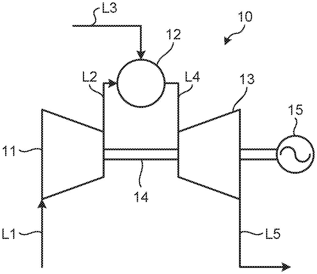
[0027] FIG. 1 is a schematic diagram illustrating a general configuration of a gas turbine according to an embodiment of the present invention.
[0028] FIG. 2 is a sectional view illustrating a main part of a compressor according to the embodiment.
[0029] FIG. 3 is a schematic side view illustrating a relation between a leakage air flow path and compressor stator vanes.
[0030] FIG. 4 is a schematic plan view illustrating a relation between the leakage air flow path and the compressor stator vanes.
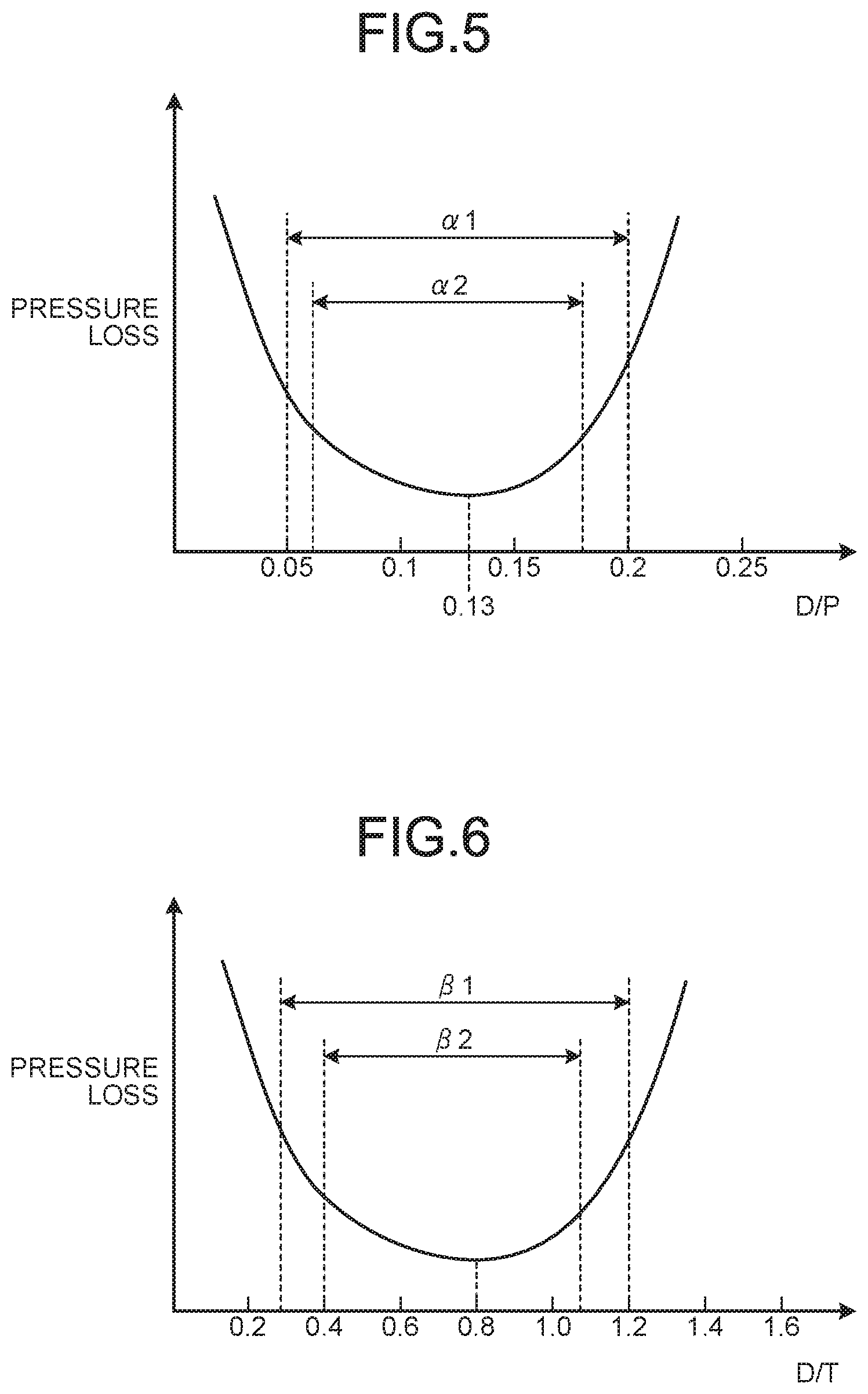
[0031] FIG. 5 is a graph illustrating pressure loss relative to D/P.
[0032] FIG. 6 is a graph illustrating pressure loss relative to D/T.
DESCRIPTION OF EMBODIMENT
[0033] The following describes a preferred embodiment of a compressor stator vane unit, a compressor, and a gas turbine according to the present invention with reference to the accompanying drawings. The embodiment is not presented to limit the scope of the present invention. If there are a plurality of embodiments, combinations of the embodiments are also included in the scope of the present invention.
[0034] FIG. 1 is a schematic diagram illustrating a general configuration of a gas turbine according to the present embodiment.
[0035] In the present embodiment, as illustrated in FIG. 1, the gas turbine 10 includes a compressor 11, a combustor 12, and a turbine 13. The compressor 11 is integrally and rotatably connected with the turbine 13 by a rotor (rotation shaft) 14, and the rotor 14 is connected with a generator 15. The compressor 11 is connected with an air intake line L1 and a compressed air feed line L2. The combustor 12 is connected with the compressed air feed line L2 and a fuel gas feed line L3. The combustor 12 is connected with the turbine 13 via a combustion gas feed line L4. The turbine 13 is connected with an exhaust gas line L5.
[0036] In the gas turbine 10, the compressor 11 compresses air taken from the air intake line L1, and the combustor 12 mixes the compressed air supplied from the compressed air feed line L2 with fuel gas supplied from the fuel gas feed line L3 and burns the mixture. The turbine 13 is rotationally driven by the combustion gas supplied from the combustion gas feed line L4, and then the generator 15 generates power. Flue gas emitted from the turbine 13 is discharged through the exhaust gas line L5.
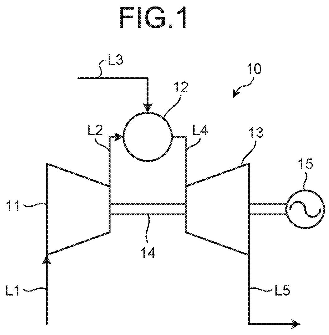
[0037] FIG. 2 is a sectional view illustrating a main part of the compressor according to the present embodiment.
[0038] As illustrated in FIGS. 1 and 2, the compressor 11 includes a casing 21, the rotor 14, multiple compressor stator vane units 22, and multiple compressor rotor blade units 23. The rotor 14 is disposed in and rotatably supported by the casing 21. The multiple compressor stator vane units 22 are disposed at a certain interval in an axial direction A of the rotor 14. Each of the compressor stator vane units 22 includes multiple compressor stator vanes 31 disposed at a certain interval in a circumferential direction. Outer ends of the compressor stator vanes 31 in a radial direction R are fixed to an inner circumferential surface 21a of the casing 21. Inner ends of the compressor stator vanes 31 in the radial direction R are connected with an annular shroud (joint member) 32.
[0039] The multiple compressor rotor blade units 23 are disposed at a certain interval in the axial direction A of the rotor 14. The multiple compressor rotor blade units 23 and the multiple compressor stator vane units 22 are alternately arranged in the axial direction A of the rotor 14. Each of the compressor rotor blade rotor units 23 includes multiple compressor rotor blades 33 disposed at a certain interval in the circumferential direction. Inner ends of the compressor rotor blades 33 in the radial direction R are fixed to an outer circumference of a disk 34 fixed to the rotor 14. The multiple compressor rotor blades 33 extend in the radial direction R and their outer ends are located close to the inner circumferential surface 21a of the casing 21.
[0040] In this structure, compressor rotor blades 33 is disposed at one side of the compressor stator vanes and other compressor rotor blades 33 is disposed at the other side of the same compressor stator vanes 31 in the axial direction A of the rotor 14. In other words, the compressor rotor blades 33 at the one side are disposed adjacent to an upstream side of the compressor stator vanes 31 in an air flow direction A1 of a main gas flow path 35, and the compressor rotor blades 33 at the other side are disposed adjacent to a downstream side of the same compressor stator vanes 31 in the air flow direction A1 of the main gas flow path 35. The main gas flow path 35 is defined by the inner circumferential surface 21a of the casing 21, the shroud 32 of the compressor stator vanes 31, and platforms 36 of the compressor rotor blades 33.
[0041] A cavity 37 is formed between the shroud 32 of the compressor stator vanes 31 and the disk 34. That is, the shroud 32 of the compressor stator vanes 31 constitutes an outer diameter side surface of the cavity 37. A first leakage air flow path 38 is provided between the compressor stator vanes 31 and the compressor rotor blades 33 at the other side. The first leakage air flow path 38 allows the main gas flow path 35 to communicate with the cavity 37. A second leakage air flow path 39 is provided between the same compressor stator vanes 31 and the compressor rotor blades 33 at the one side. The second leakage air flow path 39 allows the main gas flow path 35 to communicate with the cavity 37. The first leakage air flow path 38 is communicated with the cavity 37 at a downstream side of a trailing edge 31b of the compressor stator vanes 31 in the air flow direction A1, and the second leakage air flow path 39 is communicated with the cavity 37 at an upstream side of a leading edge 31a of the same compressor stator vanes 31 in the air flow direction A1. A leakage fluid flow path according to the present invention is provided close to a center of the shroud 32 (rotor 14), that is, an inner diameter side of the shroud 32, and includes the cavity 37, the first leakage air flow path 38 and the second leakage air flow path 39. The first leakage air flow path 38 is provided with a labyrinth seal (seal member) 40. The labyrinth seal 40 provides a seal to the first leakage air flow path 38 to prevent the compressed air in the main gas flow path 35 close to the trailing edge 31b of the compressor stator vanes 31 from flowing into the cavity 37.
[0042] The compressor 11 takes air from an air intake (not illustrated) and compresses the air while the air is passing through the multiple compressor stator vane units 22 and the multiple compressor rotor blade units 23 that are alternately arranged to generate high-temperature and high-pressure compressed air. The compressed air in a high-pressure space H located downstream in the air flow direction A1 leaks through the first leakage air flow path 38, the cavity 37, and the second leakage air flow path 39 into a low-pressure space L located upstream in the air flow direction A1. Although the first leakage air flow path 38 is provided with the labyrinth seal 40, a small amount of compressed air tends to leak. When this leakage air mixes with the compressed air flowing in the main gas flow path 35, it generates a secondary flow and causes pressure loss.
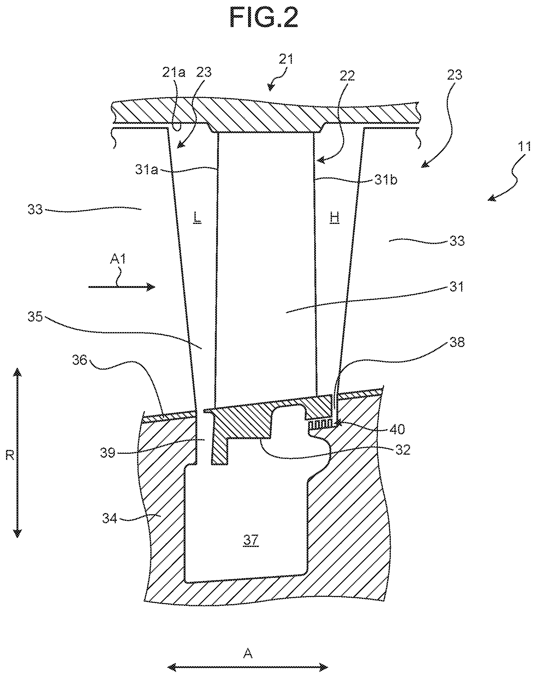
[0043] In the present embodiment, the secondary flow is prevented from being generated by providing the second leakage air flow path 39 that communicates with the low-pressure space L in the main gas flow path 35 at an optimal position, and thus the pressure loss is prevented from being generated. FIG. 3 is a schematic side view illustrating a relation between the leakage air flow path and the compressor stator vanes, and FIG. 4 is a schematic plan view illustrating a relation between the leakage air flow path and the compressor stator vanes.
[0044] In the present embodiment, as illustrated in FIGS. 3 and 4, assume that a distance in the axial direction A between an opening of the second leakage air flow path 39 close to the low-pressure space L and the leading edge (edge) 31a of the compressor stator vanes 31 located upstream in the air flow direction A1 is defined as D (hereinafter referred to as an opening distance D), and a pitch between the compressor stator vanes 31 in the circumferential direction C is defined as P (hereinafter referred to as a compressor stator vane pitch P). In this case, a ratio of the opening distance D to the compressor stator vane pitch P, or D/P, is set to the following range:
0.05.ltoreq.D/P.ltoreq.0.2.
[0045] It is preferred that the ratio of the opening distance D to the compressor stator vane pitch P, or D/P, is narrowed to the following range:
0.06.ltoreq.D/P.ltoreq.0.18.
[0046] Assume that a maximum thickness of the compressor stator vanes 31 is defined as T (hereinafter referred to as a compressor stator vane maximum thickness T). In this case, a ratio of the opening distance D to the compressor stator vane maximum thickness T, or D/T, is set to the following range:
0.3.ltoreq.D/T.ltoreq.1.2.
[0047] It is preferred that the ratio of the opening distance D to the compressor stator vane maximum thickness T, or D/T, is narrowed to the following range:
0.4.ltoreq.D/T.ltoreq.1.1.
[0048] The opening distance D is, specifically, a distance in the axial direction A between an end surface 39a of the second leakage air flow path 39 located downstream in the air flow direction A1, which corresponds to an upstream end surface of the shroud 32 in the air flow direction A1, and the leading edge 31a of the compressor stator vanes 31 at a position at which the second leakage air flow path 39 communicates with the main gas flow path 35. A curved portion 41 is provided between the leading edge 31a of the compressor stator vane 31 and an outer surface 32a of the shroud 32. A curved portion 42 is provided between the outer surface 32a of the shroud 32 and the end surface 39a of the second leakage air flow path 39. Assume that a distance in the axial direction A from a boundary between the outer surface 32a of the shroud 32 and the curved portion 42 to a boundary between the leading edge 31a of the compressor stator vanes 31 and the curved portion 41 is defined as D1, and a distance in the axial direction A from the end surface 39a of the second air flow path 39 to the boundary between the outer surface 32a of the shroud 32 and the curved portion 42, that is, a distance of the curved portion 42 in the axial direction A, is defined as D2. In this case, a relation between the opening distance D and the distance D2 can be written as follows:
0.2.ltoreq.D2/D.ltoreq.1.0.
[0049] The multiple compressor stator vanes 31 are disposed at a certain regular interval in the circumferential direction C. The compressor stator vane pitch P is, specifically, a length between two adjacent compressor stator vanes 31 in the circumferential direction C at a position closest to the shroud 32, and more specifically, at a position of the boundary between the leading edge 31a of the compressor stator vanes 31 and the curved portion 41. The compressor stator vane maximum thickness T is, specifically, a thickness of a compressor stator vane 31 at a position closest to the shroud 32, and more specifically, at a position of the boundary between the leading edge 31a of the compressor stator vane 31 and the curved portion 41. In this case, the compressor stator vane maximum thickness T is a thickness of the compressor stator vane 31 in a direction orthogonal to the direction of a chord length E of the compressor stator vane 31. A relation between the opening distance D and the chord length E can be written as follows:
2D.ltoreq.E.ltoreq.250D.
[0050] It should be noted that an angle .theta. between a direction of the chord length E and the axial direction A is set to a range: 10 degrees.ltoreq..theta..ltoreq.80 degrees.
[0051] When the leakage air flowing out from the second leakage air flow path 39 mixes with the main flow of the compressed air in the low-pressure space L of the main gas flow path 35, the leakage air typically generates the secondary flow and causes the pressure loss. However, the opening (end surface 39a) of the second leakage air flow path 39 is disposed at an optimal position relative to the leading edge 31a of the compressor stator vanes 31, and this configuration prevents generation of the secondary flow and the pressure loss.
[0052] FIG. 5 is a graph illustrating the pressure loss relative to D/P, and FIG. 6 is a graph illustrating the pressure loss relative to D/T. Data of the pressure loss illustrated in FIGS. 5 and 6 is measured when the gas turbine 10 is operated at a rated speed range ranging from 2500 rpm to 4000 rpm. More specifically, the data of the pressure loss illustrated in FIGS. 5 and 6 is measured when the gas turbine 10 is operated at the rated speed range and having a velocity of air flowing in the axial direction through a region between the compressor stator vanes 31 ranging from 50 m/s to 200 m/s.
[0053] As illustrated in FIG. 5, the pressure loss is smallest when the ratio of the opening distance D to the compressor stator vane pitch P, or D/P, is 0.13, and the pressure loss increases as D/P decreases or increases from 0.13. It is preferred that the ratio D/P is set to a range .alpha.1 of 0.05.ltoreq.D/P.ltoreq.0.2, and more preferably, set to a range .alpha.2 of 0.06.ltoreq.D/P.ltoreq.0.18. Due to a lower pressure at the back side and a higher pressure at the front side of the compressor stator vanes 31, a pressure differential in the circumferential direction is generated at the leading edge 31a. Therefore, when the ratio D/P is smaller than 0.05, the pressure differential will easily act upon the opening of the second leakage air flow path 39, and the secondary flow is more likely to occur and causes the pressure loss. When the ratio D/P is larger than 0.2, the pressure differential is less likely to act upon the opening of the second leakage air flow path 39 but the pressure loss increases due to a larger outer surface of the shroud 32 close to the leading edge 31a of the compressor stator vanes 31. In particular, when the ratio D/P is out of the range .alpha.1, the pressure loss increases significantly. When the ratio D/P is out of the range .alpha.2, the pressure loss is equal to or larger than two times or more of the smallest pressure loss at the ratio D/P of 0.13. In the present embodiment, analytical models are used to calculate the pressure loss occurring between the compressor stator vane inlet and the compressor stator vane outlet in a range of 20% of a height from a platform to a tip of the compressor stator vane with a full length of the compressor stator vane being 100%.
[0054] As illustrated in FIG. 6, when the ratio of the opening distance D to the compressor stator vane maximum thickness T, or D/T, is 0.8, the pressure loss is smallest, and when the ratio D/T is larger than 0.8, the pressure loss increases due to an increase of a flow area. When the ratio D/T is smaller than 0.8, the leading edge 31a of the compressor stator vanes 31 becomes close to the opening 39, and the leakage is induced due to an effect of a potential field of the compressor stator vane, and thus the pressure loss increases. It is preferred that the ratio D/T is set to a range .beta.1 of 0.3.ltoreq.D/T.ltoreq.1.2, and more preferably, to a range .beta.2 of 0.4.ltoreq.D/T.ltoreq.1.1.
[0055] In the compressor stator vane unit according to the present embodiment, when the distance in the axial direction A between the opening of the second leakage air flow path 39 close to the low-pressure space L and the leading edge 31a of the compressor stator vanes 31 located upstream in the air flow direction A1 is D, and when the pitch between the compressor stator vanes 31 in the circumferential direction C is P, the ratio D/P is set to 0.05.ltoreq.D/P.ltoreq.0.2. In this case, it is preferred that the ratio D/P is set to 0.06.ltoreq.D/P.ltoreq.0.18.
[0056] Setting the ratio of the opening distance D to the compressor stator vane pitch P, or D/P, to a suitable range can prevent the interference between the main flow of the compressed air and the leakage air and can prevent the generation of the secondary flow, when the air in the high-pressure space H leaks through the first leakage air flow path 38, the cavity 37, and the second leakage air flow path 39 into the low-pressure space L. This configuration can prevent the leakage air from flowing out without increasing the structural complexity or the manufacturing cost, and can prevent the pressure loss.
[0057] In the compressor stator vane unit according to the present embodiment, when the distance in the axial direction A between the opening of the second leakage air flow path 39 close to the low-pressure space L and the leading edge 31a of the compressor stator vanes 31 located upstream in the air flow direction A1 is D, and when the maximum thickness of the compressor stator vanes 31 is T, the ratio D/T is set in the range .beta.1 of 0.3.ltoreq.D/T.ltoreq.1.2. In this case, it is preferred that the ratio D/T is set in the range .beta.2 of 0.4.ltoreq.D/T.ltoreq.1.1. When the ratio D/T is out of the range .beta.1, the pressure loss increases significantly, and thus it is preferred that the ratio D/T is set in the range .beta.1. When the ratio D/T is set in the range .beta.2, the pressure loss is approximately smaller than two times or more of the smallest pressure loss at D/T=0.8.
[0058] Setting the ratio of the opening distance D to the maximum thickness T, or D/T, to an appropriate range can prevent the interference between the main flow of the compressed air and the leakage air and can prevent the generation of the secondary flow, when the air in the high-pressure space H leaks through the first leakage air flow path 38, the cavity 37, and the second leakage air flow path 39 into the low-pressure space L. This configuration can prevent the leakage air from flowing out without increasing the structural complexity or the manufacturing cost, and can prevent the pressure loss.
[0059] The compressor according to the present embodiment includes the casing 21, the rotor 14 disposed in and rotatably supported by the casing 21, the multiple compressor stator vane units 22 fixed to the inner circumferential surface 21a of the casing 21 at a certain interval in the axial direction A of the rotor 14, and the multiple compressor rotor blade units 23 including the multiple compressor rotor blades 33 fixed to the outer circumference of the rotor 14 at a certain interval in the circumferential direction C, the multiple compressor rotor blade units 23 being fixed to the outer circumference of the rotor 14 at a certain interval in the axial direction. This configuration enables the compressor 11 to prevent the leakage air from flowing out without increasing the structural complexity or the manufacturing cost, and can prevent the pressure loss.
[0060] The gas turbine according to the present embodiment includes the compressor 11, the combustor 12 that mixes the compressed air compressed by the compressor 11 with a fuel and burns the mixture, and the turbine 13 rotationally driven by combustion gas generated by the combustor 12. This configuration enables the gas turbine 10 to prevent the leakage air from flowing out without increasing the structural complexity or the manufacturing cost, and can prevent the pressure loss.
REFERENCE SIGNS LIST
[0061] 10 Gas turbine [0062] 11 Compressor [0063] 12 Combustor [0064] 13 Turbine [0065] 14 Rotor (rotation shaft) [0066] 15 Generator [0067] 21 Casing [0068] 21a Inner circumferential surface [0069] 22 Compressor stator vane unit [0070] 23 Compressor rotor blade unit [0071] 31 Compressor stator vane [0072] 31a Leading edge (edge) [0073] 31b Trailing edge [0074] 32 Shroud (joint member) [0075] 33 Compressor rotor blade [0076] 34 Disk [0077] 35 Main gas flow path [0078] 36 Platform [0079] 37 Cavity (leakage fluid flow path) [0080] 38 First leakage air flow path (leakage fluid flow path) [0081] 39 Second leakage air flow path (leakage fluid flow path) [0082] 40 Labyrinth seal (seal member) [0083] D Opening distance [0084] P Compressor stator vane pitch [0085] T Compressor stator vane maximum thickness [0086] E Chord length [0087] H High-pressure space [0088] L Low-pressure space [0089] A Axial direction [0090] A1 Air flow direction [0091] C Circumferential direction [0092] R Radial direction [0093] L1 Air intake line [0094] L2 Compressed air feed line [0095] L3 Fuel gas feed line [0096] L4 Combustion gas feed line [0097] L5 Exhaust gas line
* * * * *
D00000
D00001
D00002
D00003
D00004
XML
uspto.report is an independent third-party trademark research tool that is not affiliated, endorsed, or sponsored by the United States Patent and Trademark Office (USPTO) or any other governmental organization. The information provided by uspto.report is based on publicly available data at the time of writing and is intended for informational purposes only.
While we strive to provide accurate and up-to-date information, we do not guarantee the accuracy, completeness, reliability, or suitability of the information displayed on this site. The use of this site is at your own risk. Any reliance you place on such information is therefore strictly at your own risk.
All official trademark data, including owner information, should be verified by visiting the official USPTO website at www.uspto.gov. This site is not intended to replace professional legal advice and should not be used as a substitute for consulting with a legal professional who is knowledgeable about trademark law.