Robotic Surgical System With An Embedded Imager
Meglan; Dwight ; et al.
U.S. patent application number 16/305685 was filed with the patent office on 2020-10-15 for robotic surgical system with an embedded imager. The applicant listed for this patent is Covidien LP. Invention is credited to Kashif Ikram, Dwight Meglan.
| Application Number | 20200323608 16/305685 |
| Document ID | / |
| Family ID | 1000004971503 |
| Filed Date | 2020-10-15 |


| United States Patent Application | 20200323608 |
| Kind Code | A1 |
| Meglan; Dwight ; et al. | October 15, 2020 |
ROBOTIC SURGICAL SYSTEM WITH AN EMBEDDED IMAGER
Abstract
The present disclosure is directed to a robotic surgical system and a corresponding method. The system includes at least one robot arm and a radiation source coupled to the robot arm. The system also includes a surgical table having a digital imaging receiver configured to output an electrical signal based on radiation received from the radiation source. A controller having a processor and a memory is configured to receive the electrical signal and generate an initial image of a patient on the surgical table based on the electrical signal. The controller transforms the initial image to a transformed image based on an orientation of the radiation source.
| Inventors: | Meglan; Dwight; (Westwood, MA) ; Ikram; Kashif; (Zurich, CH) | ||||||||||
| Applicant: |
|
||||||||||
|---|---|---|---|---|---|---|---|---|---|---|---|
| Family ID: | 1000004971503 | ||||||||||
| Appl. No.: | 16/305685 | ||||||||||
| Filed: | June 2, 2017 | ||||||||||
| PCT Filed: | June 2, 2017 | ||||||||||
| PCT NO: | PCT/US2017/035582 | ||||||||||
| 371 Date: | November 29, 2018 |
Related U.S. Patent Documents
| Application Number | Filing Date | Patent Number | ||
|---|---|---|---|---|
| 62345168 | Jun 3, 2016 | |||
| Current U.S. Class: | 1/1 |
| Current CPC Class: | A61B 34/37 20160201; A61B 2090/367 20160201; A61B 90/37 20160201; A61B 34/70 20160201; A61B 2090/376 20160201 |
| International Class: | A61B 90/00 20060101 A61B090/00; A61B 34/37 20060101 A61B034/37; A61B 34/00 20060101 A61B034/00 |
Claims
1. A robotic surgical system comprising: at least one robot arm; a radiation source removably coupled to the robot arm; a surgical table having a digital imaging receiver configured to output an electrical signal based on radiation received from the radiation source; and a controller having a processor and a memory, the controller is configured to receive the electrical signal and generate an initial image of a patient on the surgical table based on the electrical signal, wherein the controller transforms the initial image to a transformed image based on an orientation of the radiation source relative to the digital imaging receiver.
2. The robotic surgical system of claim 1, wherein the controller determines a pose of the radiation source relative to the digital imaging receiver.
3. The robotic surgical system of claim 2, wherein the pose includes an angle between an imaging axis defined by the radiation source and an axis extending perpendicular to a plane defined by the digital imaging receiver.
4. The robotic surgical system of claim 3, wherein the pose includes a position of the radiation source relative to the digital imaging receiver.
5. The robotic surgical system of claim 2, wherein the controller transforms the initial image to the transformed image based on the determined pose.
6. The robotic surgical system of claim 1, wherein the initial image is an angled view of the patient along an imaging axis of the radiation source.
7. The robotic surgical system of claim 1, wherein the controller executes a movement plan to generate a 3D reconstruction of a patient.
8. The robotic surgical system of claim 7, wherein the movement plan causes the controller to move the radiation source a plurality of times.
9. The robotic surgical system of claim 8, wherein the controller generates a plurality of initial images, wherein each initial image corresponds to each time the radiation source is moved.
10. The robotic surgical system of claim 9, wherein the controller transforms the plurality of initial images to a plurality of slices.
11. The robotic surgical system of claim 10, wherein the 3D reconstruction is based on the plurality of slices.
12. A method for imaging a patient using a robotic surgical system, the method comprising: emitting radiation from a radiation source; receiving radiation from the radiation source using a digital imaging receiver; converting the received radiation into an electrical signal; converting the electrical signal into an initial image; and transforming the initial image to a transformed image based on a pose of the radiation source relative to the digital image receiver.
13. The method of claim 12, further including determining the pose of the radiation source relative to the digital image receiver from a position of the radiation source and an angle between an imaging axis defined by the radiation source and an axis extending perpendicular to a plane defined by the digital image receiver.
14. The method of claim 13, wherein the initial image is transformed into the transformed image based on the pose.
15. The method of claim 12, wherein the initial image is an angled view of the patient.
16. The method of claim 12, further including executing a movement plan to generate a 3D reconstruction of a patient.
17. The method of claim 16, wherein the movement plan causes the radiation source to move a plurality of times.
18. The method of claim 17, further including generating a plurality of initial images, wherein each initial image corresponds to each time the radiation source is moved.
19. The method of claim 18, wherein the plurality of initial images is transformed into a plurality of slices.
20. The method of claim 19, wherein the 3D reconstruction is based on the plurality of slices.
Description
CROSS-REFERENCE TO RELATED APPLICATIONS
[0001] This application claims the benefit of and priority to U.S. Provisional Application No. 62/345,168, filed on Jun. 3, 2016, the entire contents of which are incorporated by reference herein.
BACKGROUND
[0002] Robotic surgical systems such as teleoperative systems are used to perform minimally invasive surgical procedures that offer many benefits over traditional open surgery techniques, including less pain, shorter hospital stays, quicker return to normal activities, minimal scarring, reduced recovery time, and less injury to tissue.
[0003] Robotic surgical systems can have a number of robotic arms that move attached instruments or tools, such as an image capturing device, a grasper, a stapler, an electrosurgical instrument, etc., in response to movement of input devices by a surgeon viewing images captured by the image capturing device of a surgical site. During a surgical procedure, each of the tools may be inserted through an opening, e.g., a laparoscopic port, into the patient and positioned to manipulate tissue at a surgical site. The openings are placed about the patient's body so that the surgical instruments may be used to cooperatively perform the surgical procedure and the image capturing device may view the surgical site.
[0004] During the surgical procedure, radiographic imaging may be required to see the status of a patient's internal anatomical structure as well as the location of any surgical tools located therein. The radiographic imaging is performed by a c-arm style fluoroscope that is brought into the operating room or is a dedicated fluoroscope installed within the operating room. The robotic surgical system may have to be disconnected from the patient and moved out of the way in order to position the fluoroscope around the patient to obtain the radiographic images. The disconnecting, movement, and reconnecting of the robotic surgical system will delay the surgical procedure. As a result of this delay, radiographic images may not be fully utilized as a safety monitoring step or to monitor progress of the surgical procedure.
[0005] Accordingly, there is a need for obtaining radiographic images without moving the surgical robotic surgical system.
SUMMARY
[0006] In an aspect of the present disclosure, a robotic surgical system is provided. The robotic surgical system includes at least one robot arm and a radiation source removably coupled to the robot arm. The system also includes a surgical table having a digital imaging receiver configured to output an electrical signal based on radiation received from the radiation source. A controller having a processor and a memory is configured to receive the electrical signal and generate an initial image of a patient on the surgical table based on the electrical signal. The controller transforms the initial image to a transformed image based on an orientation of the radiation source relative to the digital imaging receiver.
[0007] In embodiments, the controller determines a pose of the radiation source relative to the digital imaging receiver. The pose may include an angle between an imaging axis defined by the radiation source and an axis extending perpendicular to a plane defined by the digital imaging receiver. The pose may include a position of the radiation source relative to the digital imaging receiver.
[0008] The controller may transform the initial image to the transformed image based on the angle.
[0009] In some embodiments, the initial image may be an angled view (e.g., non-perpendicular) of the patient along an imaging axis of the radiation source.
[0010] In some embodiments, the controller may execute a movement plan to generate a 3D reconstruction of a patient. The movement plan may cause the controller to move the radiation source a plurality of times. The controller may generate a plurality of initial images, wherein each initial image corresponds to each time the radiation source is moved. The plurality of initial images may be transformed into a plurality of slices that are used to generate the 3D reconstruction.
[0011] In another aspect of the present disclosure, a method for imaging a patient using a robotic surgical system is provided. The method includes emitting radiation from a radiation source, receiving radiation from the radiation source using a digital imaging receiver included in a surgical table, and converting the received radiation into an electrical signal. The electrical signal is converted into an initial image which is transformed into a transformed image based on a pose of the radiation source relative to the digital image receiver.
[0012] In some embodiments, the method also includes determining the pose of the radiation source relative to the digital image receiver from a position of the radiation source and an angle between an imaging axis defined by the radiation source and a line perpendicular to a plane defined by the digital image receiver. The initial image is transformed into the transformed image based on the pose.
[0013] In some embodiments, the initial image may be an angled view of the patient.
[0014] In some embodiments, a movement plan is executed to generate a 3D reconstruction of a patient. The movement plan may cause the radiation source to move a plurality of times. A plurality of initial images would be generated, wherein each initial image corresponds to each time the radiation source is moved. The plurality of initial images may be transformed into a plurality of slices that are used to generate the 3D reconstruction.
BRIEF DESCRIPTION OF THE DRAWINGS
[0015] Various aspects of the present disclosure are described hereinbelow with reference to the drawings, which are incorporated in and constitute a part of this specification, wherein:
[0016] FIG. 1 is a schematic illustration of a user interface and a robotic system of a robotic surgical system in accordance with the present disclosure;
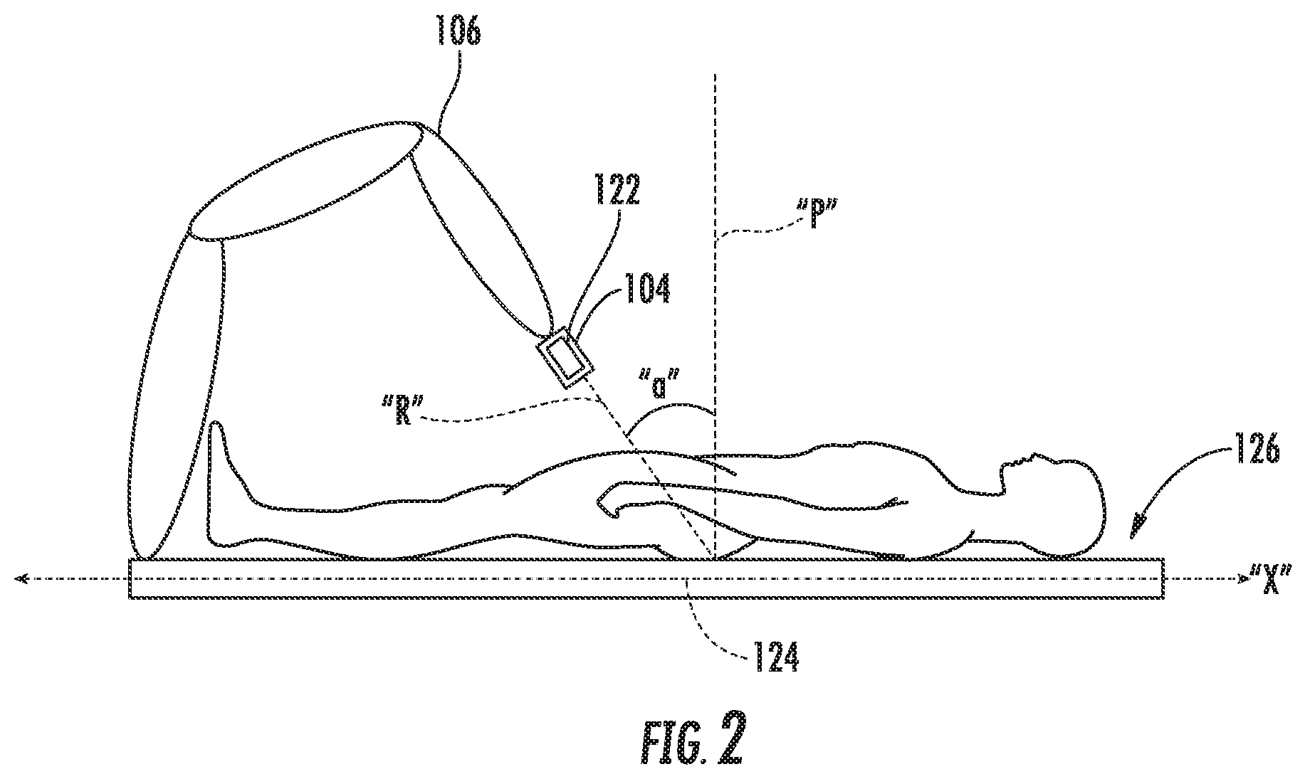
[0017] FIG. 2 is a schematic illustration of an imaging system in accordance with the present disclosure;
[0018] FIG. 3 is a flowchart depicting operation of the imaging system of the present disclosure; and
[0019] FIG. 4 is a flowchart depicting another operation of the imaging system of the present disclosure.
DETAILED DESCRIPTION
[0020] Fluoroscopic images may be obtained without the use of traditional C-arm style fluoroscopes. The present disclosure is directed to systems and methods for obtaining fluoroscopic images using a robotic surgical system. In the systems described herein, a radiation source is incorporated into an end effector attached to an arm of the robotic surgical system. A receiver can incorporated into the surgical table or place on the surgical table. The receiver is configured to receive x-rays emitted by the radiation source. The received x-rays are converted into an image with an angled perspective which is thereafter transformed into an image with a perpendicular perspective relative to the patient.
[0021] By placing the radiation source as an end effector on the robotic arm and the receiver on the operating table, a radiograph may be produced without having to move the surgical robot out of the way of a separate imaging device, e.g., c-arm style fluoroscope or dedicated fluoroscope. By knowing the angle of an orientation of the end effector relative to a plane defined by the surface of the operating table, the obtained images may be corrected to produce an appropriate image, i.e., a perpendicular perspective of the patient.
[0022] Turning to FIG. 1, a robotic surgical system 100 may be employed with one or more consoles 102 that are next to the operating theater or located in a remote location. In this instance, one team of clinicians or nurses may prep the patient for surgery and configure the robotic surgical system 100 with one or more end effectors 104 while another clinician (or group of clinicians) remotely controls the instruments via the robotic surgical system 100. As can be appreciated, a highly skilled clinician may perform multiple operations in multiple locations without leaving his/her remote console which can be both economically advantageous and a benefit to the patient or a series of patients.
[0023] The robotic arms 106 of the surgical system 100 are typically coupled to a pair of master handles 108 by a controller 110. Controller 110 may be integrated with the console 102 or provided as a standalone device within the operating theater. The handles 106 can be moved by the clinician to produce a corresponding movement of the working ends of any type of end effector 104 (e.g., probes, mechanical or electrosurgical end effectors, graspers, knifes, scissors, staplers, etc.) attached to the robotic arms 106. For example, end effector 104 may be a probe that includes an image capture device.
[0024] The console 102 includes a display device 112 which is configured to display two-dimensional or three-dimensional images. The display device 112 displays the images of the surgical site which may include data captured by end effector 104 positioned on the ends 114 of the arms 106 and/or include data captured by imaging devices that are positioned about the surgical theater (e.g., an imaging device positioned within the surgical site, an imaging device positioned adjacent the patient, imaging device positioned at a distal end of an imaging arm). The imaging devices may capture visual images, infra-red images, ultrasound images, X-ray images, thermal images, and/or any other known real-time images of the surgical site. The imaging devices transmit captured imaging data to the controller 110 which creates the images of the surgical site in real-time from the imaging data and transmits the images to the display device 112 for display.
[0025] The movement of the master handles 108 may be scaled so that the working ends have a corresponding movement that is different, smaller or larger, than the movement performed by the operating hands of the clinician. The scale factor or gearing ratio may be adjustable so that the operator can control the resolution of the working ends of the end effector 104.
[0026] During operation of the surgical system 100, the master handles 108 are operated by a clinician to produce a corresponding movement of the robotic arms 106 and/or end effector 104. The master handles 108 provide a signal to the controller 110 which then provides a corresponding signal to one or more drive motors 114. The one or more drive motors 114 are coupled to the robotic arms 106 in order to move the robotic arms 106 and/or end effector 104.
[0027] The master handles 108 may include various haptics 116 to provide feedback to the clinician relating to various tissue parameters or conditions, e.g., tissue resistance due to manipulation, cutting or otherwise treating, pressure by the instrument onto the tissue, tissue temperature, tissue impedance, etc. As can be appreciated, such haptics 116 provide the clinician with enhanced tactile feedback simulating actual operating conditions. The haptics 116 may include vibratory motors, electroactive polymers, piezoelectric devices, electrostatic devices, subsonic audio wave surface actuation devices, reverse-electrovibration, or any other device capable of providing a tactile feedback to a user. The master handles 108 may also include a variety of different actuators (not shown) for delicate tissue manipulation or treatment further enhancing the clinician's ability to mimic actual operating conditions.
[0028] The controller 110 includes a transceiver 118 and a processor 120. Transceiver 118 receives a signal from a radiation source 122 disposed on end effector 104 indicating a position and orientation of the radiation source 122 and a signal from a digital imaging receiver (DIR) 124 disposed on or in the operating table 126, which will be described in more detail below. In some embodiments, the processor 120 may determine the position and orientation of the radiation source 122. The signals from radiation source 122 and/or DIR 124 may be transmitted to transceiver 118 via any conventional wired or wireless methods. Transceiver 118 provides the signal to an image generating unit 128 in processor 120 which generates an image based on the position and orientation of the radiation source 122 and the DIR 124. A memory 130 may store an algorithm used to perform the image generation.
[0029] Turning to FIG. 2, while making reference to FIG. 1, a clinician may attach an end effector 104 including a radiation source 122 to one of the robotic arms 106. The radiation source 122 emits x-rays toward the patient. As the x-rays pass through the patient, the x-rays are attenuated by different amounts as they pass through, having some energy absorbed, or deflect off of various tissues in the patient. The attenuated x-rays are received by the DIR 124 which converts the received x-rays into electrical signals that are provided to the image generating unit 128. The image generating unit converts the electrical signals into an initial image which represents an angled view of the patient.
[0030] Once the initial image is generated, the image generating unit 128 uses a pose including the position and the orientation of the radiation source 122 to perform an affine transformation in which the initial image is transformed into a transformed image that would be displayed on display 112. It will be appreciated that the initial image may be a skewed image that is at least keystoned into the transformed image. The perpendicular view presents a view perpendicular the imaging axis "R".
[0031] It is contemplated that the transformed image could be a view perpendicular to the patient such that the displayed view is a top plan view perpendicular to a longitudinal axis of the patient. For example, as shown in FIG. 2, the orientation of the radiation source is represented by the angle "a". Angle "a" is the angle between an imaging axis "R" extending through the radiation source 122 and a line "P" perpendicular to the plane "X" of the operating table 126. Based on the angle "a", the image generating unit could perform a transformation of the initial image to the top plan displayed image.
[0032] FIG. 3 is a flow chart depicting operation of the imaging system in accordance with embodiments of the present disclosure. FIG. 3 will be described below in conjunction with FIGS. 1 and 2. As shown in FIG. 3, the radiation source 122 is moved into position in step s302. Once in position, the processor 120 determines or receives the pose of the radiation source 122, including the position and the orientation of the radiation source 122, to determine the angle "a" in step s304. In step s306, the processor 120 determines if angle "a" is less than a predetermined angle "p". If angle "a" is not less than predetermined angle "p", the resulting transformed image may not work well or at all. If the angle "a" is not less than the angle "p", the process returns to step s302 where the radiation source is moved. For example, if the misalignment of the predetermined angle "p" and the imaging axis "R" is large, the keystone transformation may create a crude image as a result of large pixilation at one end of the image. If the angle "a" is less than the angle "p", the process proceeds to step s308, where the initial image is generated based on the x-rays received by the DIR 124. The initial image is then transformed in step s310 by the image generating unit 128 to generate a transformed image. The transformed image is then displayed on display 112 in step s312. In step s314, a user may decide to end the procedure or continue the procedure. If the procedure is continued, the user may then determine if the radiation source 122 needs to be moved in step s316. If the radiation source does not need to be moved, the process returns to step s308. If the radiation source needs to be moved, the process returns to step s302.
[0033] In some embodiments, the radiation source 122 may be moved according to a movement plan stored in the memory 130. FIG. 4, which will be discussed in conjunction with FIGS. 1 and 2, depicts a method for generating a 3D reconstruction of a patient. As shown in FIG. 4, a movement plan is executed by controller 110 (i.e., the movement plan is loaded from memory 130 to be executed by processor 120) in step s402. In step s404, the controller 110 generates an initial image by controlling the radiation source 122 to emit x-rays and receiving an electrical signal from DIR 124 based on x-rays received from the radiation source 122. The controller then transforms the initial image to an image slice based on the orientation of the radiation source 122 in step s406. For example, if the imaging axis "R" is perpendicular to the centerline of the patient, the image slice is an image of the patient parallel to a transverse plane of the patient. However, it is contemplated that the imaging axis "R" can be disposed at any angle relative to the patient. In step s408, the controller 110 determines whether the movement plan is completed. If the movement plan is not completed, the controller 110 moves the radiation source 122 in step s410 and then proceeds to step s404. If the movement plan is completed, the controller 110 uses the plurality of slices generated by the controller 110 to generate a 3D reconstruction of the patient in step s412.
[0034] The embodiments disclosed herein are examples of the disclosure and may be embodied in various forms. Specific structural and functional details disclosed herein are not to be interpreted as limiting, but as a basis for the claims and as a representative basis for teaching one skilled in the art to variously employ the present disclosure in virtually any appropriately detailed structure. Like reference numerals may refer to similar or identical elements throughout the description of the figures.
[0035] The phrases "in an embodiment," "in embodiments," "in some embodiments," or "in other embodiments," which may each refer to one or more of the same or different embodiments in accordance with the present disclosure. A phrase in the form "A or B" means "(A), (B), or (A and B)". A phrase in the form "at least one of A, B, or C" means "(A), (B), (C), (A and B), (A and C), (B and C), or (A, B and C)". A user may refer to a surgeon or any medical professional, such as a doctor, nurse, technician, medical assistant, or the like performing a medical procedure.
[0036] The systems described herein may also utilize one or more controllers to receive various information and transform the received information to generate an output. The controller may include any type of computing device, computational circuit, or any type of processor or processing circuit capable of executing a series of instructions that are stored in a memory. The controller may include multiple processors and/or multicore central processing units (CPUs) and may include any type of processor, such as a microprocessor, digital signal processor, microcontroller, or the like. The controller may also include a memory to store data and/or algorithms to perform a series of instructions.
[0037] Any of the herein described methods, programs, algorithms or codes may be converted to, or expressed in, a programming language or computer program. A "Programming Language" and "Computer Program" includes any language used to specify instructions to a computer, and includes (but is not limited to) these languages and their derivatives: Assembler, Basic, Batch files, BCPL, C, C+, C++, Delphi, Fortran, Java, JavaScript, Machine code, operating system command languages, Pascal, Perl, PL1, scripting languages, Visual Basic, metalanguages which themselves specify programs, and all first, second, third, fourth, and fifth generation computer languages. Also included are database and other data schemas, and any other meta-languages. No distinction is made between languages which are interpreted, compiled, or use both compiled and interpreted approaches. No distinction is also made between compiled and source versions of a program. Thus, reference to a program, where the programming language could exist in more than one state (such as source, compiled, object, or linked) is a reference to any and all such states. Reference to a program may encompass the actual instructions and/or the intent of those instructions.
[0038] Any of the herein described methods, programs, algorithms or codes may be contained on one or more machine-readable media or memory. The term "memory" may include a mechanism that provides (e.g., stores and/or transmits) information in a form readable by a machine such a processor, computer, or a digital processing device. For example, a memory may include a read only memory (ROM), random access memory (RAM), magnetic disk storage media, optical storage media, flash memory devices, or any other volatile or non-volatile memory storage device. Code or instructions contained thereon can be represented by carrier wave signals, infrared signals, digital signals, and by other like signals.
[0039] It should be understood that the foregoing description is only illustrative of the present disclosure. Various alternatives and modifications can be devised by those skilled in the art without departing from the disclosure. For instance, any of the augmented images described herein can be combined into a single augmented image to be displayed to a clinician. Accordingly, the present disclosure is intended to embrace all such alternatives, modifications and variances. The embodiments described with reference to the attached drawing figs. are presented only to demonstrate certain examples of the disclosure. Other elements, steps, methods and techniques that are insubstantially different from those described above and/or in the appended claims are also intended to be within the scope of the disclosure.
* * * * *
D00000
D00001
D00002
D00003
D00004
XML
uspto.report is an independent third-party trademark research tool that is not affiliated, endorsed, or sponsored by the United States Patent and Trademark Office (USPTO) or any other governmental organization. The information provided by uspto.report is based on publicly available data at the time of writing and is intended for informational purposes only.
While we strive to provide accurate and up-to-date information, we do not guarantee the accuracy, completeness, reliability, or suitability of the information displayed on this site. The use of this site is at your own risk. Any reliance you place on such information is therefore strictly at your own risk.
All official trademark data, including owner information, should be verified by visiting the official USPTO website at www.uspto.gov. This site is not intended to replace professional legal advice and should not be used as a substitute for consulting with a legal professional who is knowledgeable about trademark law.