Power Bank For Electronic Cigarette
LIU; Tuanfang
U.S. patent application number 16/561054 was filed with the patent office on 2020-10-08 for power bank for electronic cigarette. The applicant listed for this patent is Tuanfang LIU. Invention is credited to Tuanfang LIU.
| Application Number | 20200321567 16/561054 |
| Document ID | / |
| Family ID | 1000004333051 |
| Filed Date | 2020-10-08 |


| United States Patent Application | 20200321567 |
| Kind Code | A1 |
| LIU; Tuanfang | October 8, 2020 |
POWER BANK FOR ELECTRONIC CIGARETTE
Abstract
A power bank includes a face shell; a back shell; a first panel; a second panel; an on-off button; a power adjustment button; a thread ring; a seal ring; a first electrode; a spring; an insulator; a sleeve piece; a second electrode; a silica seal; a battery cell; a control board; a silicone pad; a fixed ring; a display screen; and a light guide film. The face shell and the back shell are combined to form a cylinder including a first end and a second end. The face shell includes a front face and a back face, and the first panel and the second panel are attached to the front face and the back face, respectively. The first panel includes a first groove and a second groove, and the on-off button and the power adjustment button are disposed in the first groove and the second groove, respectively.
| Inventors: | LIU; Tuanfang; (Shenzhen, CN) | ||||||||||
| Applicant: |
|
||||||||||
|---|---|---|---|---|---|---|---|---|---|---|---|
| Family ID: | 1000004333051 | ||||||||||
| Appl. No.: | 16/561054 | ||||||||||
| Filed: | September 5, 2019 |
| Current U.S. Class: | 1/1 |
| Current CPC Class: | A24F 47/008 20130101; H01M 2/105 20130101; H01M 2220/30 20130101; H01M 10/488 20130101; H01M 2/08 20130101; H01M 10/46 20130101 |
| International Class: | H01M 2/10 20060101 H01M002/10; H01M 2/08 20060101 H01M002/08; H01M 10/46 20060101 H01M010/46; H01M 10/48 20060101 H01M010/48; A24F 47/00 20060101 A24F047/00 |
Foreign Application Data
| Date | Code | Application Number |
|---|---|---|
| Apr 2, 2019 | CN | 201910262695.3 |
| Apr 2, 2019 | CN | 201920441645.7 |
Claims
1. A device, comprising: a face shell; a back shell; a first panel; a second panel; an on-off button; a power adjustment button; a thread ring; a seal ring; a first electrode; a spring; an insulator; a sleeve piece; a second electrode; a silica seal; a battery cell; a control board; a silicone pad; a fixed ring; a display screen; and a light guide film; wherein: the face shell and the back shell are combined to form a cylinder comprising a first end and a second end; the face shell comprises a front face and a back face, and the first panel and the second panel are attached to the front face and the back face, respectively; the first panel comprises a first groove and a second groove, and the on-off button and the power adjustment button are disposed in the first groove and the second groove, respectively; positive and negative terminals of the control board are connected positive and negative terminals of the battery cell; and the control board and the battery cell are disposed in the cylinder formed by the face shell and the back shell; the spring is sheathed on the first electrode; the first electrode is disposed on the insulator; the second electrode is directly connected to the first electrode; the silica seal is sheathed on the second electrode and is disposed in the sleeve piece; the thread ring is disposed on the first end of the cylinder formed by the face shell and the back shell; the seal ring is embedded in the thread ring; the sleeve piece abuts against the thread ring; and the silicone pad is disposed on the second end of the cylinder; the fixed ring is sheathed on the silicone pad; the display screen is disposed on the silicone pad; and the light guide film is attached to the display screen.
2. The device of claim 1, wherein the power adjustment button comprises six tap positions corresponding to different output powders.
Description
CROSS-REFERENCE TO RELATED APPLICATIONS
[0001] Pursuant to 35 U.S.C. .sctn. 119 and the Paris Convention Treaty, this application claims foreign priority to Chinese Patent Application No. 201910262695.3 filed Apr. 2, 2019, and to Chinese Patent Application No. 201920441645.7 filed Apr. 2, 2019. The contents of all of the aforementioned applications, including any intervening amendments thereto, are incorporated herein by reference. Inquiries from the public to applicants or assignees concerning this document or the related applications should be directed to: Matthias Scholl P.C., Attn.: Dr. Matthias Scholl Esq., 245 First Street, 18th Floor, Cambridge, Mass. 02142.
BACKGROUND
[0002] This disclosure relates to a power bank for an electronic cigarette.
[0003] Electronic cigarettes atomize nicotine-containing e-liquid. The electronic cigarettes include embedded rechargeable batteries. The rechargeable batteries can be recharged using power banks.
SUMMARY
[0004] Provided is a power bank for an electronic cigarette. The power bank comprises a face shell; a back shell; a first panel; a second panel; an on-off button; a power adjustment button; a thread ring; a seal ring; a first electrode; a spring; an insulator; a sleeve piece; a second electrode; a silica seal; a battery cell; a control board; a silicone pad; a fixed ring; a display screen; and a light guide film.
[0005] The face shell and the back shell are combined to form a cylinder comprising a first end and a second end; the face shell comprises a front face and a back face, and the first panel and the second panel are attached to the front face and the back face, respectively; the first panel comprises a first groove and a second groove, and the on-off button and the power adjustment button are disposed in the first groove and the second groove, respectively; the positive and negative terminals of the control board are connected positive and negative terminals of the battery cell; and the control board and the battery cell are disposed in the cylinder formed by the face shell and the back shell; the spring is sheathed on the first electrode; the first electrode is disposed on the insulator; the second electrode is directly connected to the first electrode; the silica seal is sheathed on the second electrode and is disposed in the sleeve piece; the thread ring is disposed on the first end of the cylinder formed by the face shell and the back shell; the seal ring is embedded in the thread ring; the sleeve piece abuts against the thread ring; and the silicone pad is disposed on the second end of the cylinder; the fixed ring is sheathed on the silicone pad; the display screen is disposed on the silicone pad; and the light guide film is attached to the display screen.
[0006] The power adjustment button can comprise six tap positions corresponding to different output powders.
[0007] Advantages of the power bank according to embodiments of the disclosure are summarized as follows. The power bank is cylindrical and compact, so it is easy to carry.
[0008] The power bank comprises a power adjustment button. Continuous pressing the power adjustment button can adjust the output power of the power bank.
BRIEF DESCRIPTION OF THE DRAWINGS
[0009] FIG. 1 is an exploded view of a power bank for an electronic cigarette according to one embodiment of the disclosure;
[0010] FIG. 2 is a stereogram of a power bank for an electronic cigarette according to one embodiment of the disclosure; and
[0011] FIG. 3 is a sectional view of a power bank for an electronic cigarette according to one embodiment of the disclosure.
DETAILED DESCRIPTION
[0012] To further illustrate, embodiments detailing a power bank for an electronic cigarette are described below. It should be noted that the following embodiments are intended to describe and not to limit the disclosure.
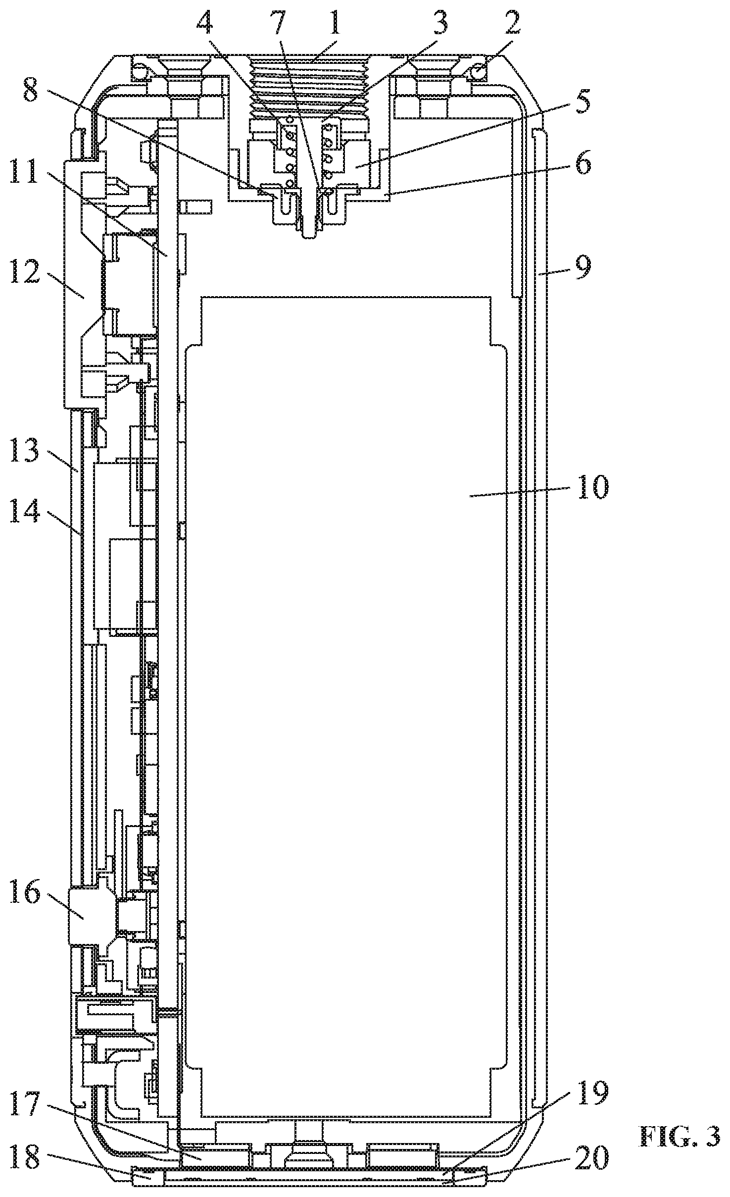
[0013] As shown in FIGS. 1-3, provided is a power bank for an electronic cigarette, comprising: a face shell 9; a back shell 15; a first panel 13; a second panel 14; an on-off button 12; a power adjustment button 16; a thread ring 1; a seal ring 2; a first electrode 3; a spring 4; an insulator 5; a sleeve piece 6; a second electrode 7; a silica seal 8; a battery cell 10; a control board 11; a silicone pad 17; a fixed ring 18; a display screen 19; and a light guide film 20.
[0014] The face shell 9 and the back shell 15 are combined to form a cylinder comprising a first end and a second end; the face shell 9 comprises a front face and a back face, and the first panel 13 and the second panel 14 are attached to the front face and the back face, respectively; the first panel 13 comprises a first groove and a second groove, and the on-off button 12 and the power adjustment button 16 are disposed in the first groove and the second groove, respectively; the positive and negative terminals of the control board 11 are connected positive and negative terminals of the battery cell 10; and the control board 11 and the battery cell 10 are disposed in the cylinder formed by the face shell 9 and the back shell 15; the spring 4 is sheathed on the first electrode 3; the first electrode 3 is disposed on the insulator 5; the second electrode 7 is directly connected to the first electrode 3; the silica seal 8 is sheathed on the second electrode 7 and is disposed in the sleeve piece 6; the thread ring 1 is disposed on the first end of the cylinder formed by the face shell 9 and the back shell 15; the seal ring 2 is embedded in the thread ring 1; the sleeve piece 6 abuts against the thread ring 1; and the silicone pad 17 is disposed on the second end of the cylinder; the fixed ring 18 is sheathed on the silicone pad 17; the display screen 19 is disposed on the silicone pad 17; and the light guide film 20 is attached to the display screen 19.
[0015] The power adjustment button 16 comprises six tap positions, so as to adjust the power bank to output different power to the electronic cigarette.
[0016] The power bank is cylindrical and compact, so it is easy to carry. The power adjustment button 16 comprises six tap positions. Continuous pressing the power adjustment button can adjust the output power of the power bank. For example, continuously press the power adjustment button six times, the power bank can output a maximum voltage. The output voltage periodically changes in six values as per the press times of the power adjustment button.
[0017] It will be obvious to those skilled in the art that changes and modifications may be made, and therefore, the aim in the appended claims is to sleeve piece all such changes and modifications.
* * * * *
D00000
D00001
D00002
D00003
XML
uspto.report is an independent third-party trademark research tool that is not affiliated, endorsed, or sponsored by the United States Patent and Trademark Office (USPTO) or any other governmental organization. The information provided by uspto.report is based on publicly available data at the time of writing and is intended for informational purposes only.
While we strive to provide accurate and up-to-date information, we do not guarantee the accuracy, completeness, reliability, or suitability of the information displayed on this site. The use of this site is at your own risk. Any reliance you place on such information is therefore strictly at your own risk.
All official trademark data, including owner information, should be verified by visiting the official USPTO website at www.uspto.gov. This site is not intended to replace professional legal advice and should not be used as a substitute for consulting with a legal professional who is knowledgeable about trademark law.